EP2476975B1 - Vorrichtung zur Wärmeübertragung für ein Fahrzeug - Google Patents
Vorrichtung zur Wärmeübertragung für ein Fahrzeug Download PDFInfo
- Publication number
- EP2476975B1 EP2476975B1 EP12150889.9A EP12150889A EP2476975B1 EP 2476975 B1 EP2476975 B1 EP 2476975B1 EP 12150889 A EP12150889 A EP 12150889A EP 2476975 B1 EP2476975 B1 EP 2476975B1
- Authority
- EP
- European Patent Office
- Prior art keywords
- volume element
- refrigerant
- flow channel
- volume
- supercooling
- Prior art date
- Legal status (The legal status is an assumption and is not a legal conclusion. Google has not performed a legal analysis and makes no representation as to the accuracy of the status listed.)
- Active
Links
Images


Classifications
-
- F—MECHANICAL ENGINEERING; LIGHTING; HEATING; WEAPONS; BLASTING
- F25—REFRIGERATION OR COOLING; COMBINED HEATING AND REFRIGERATION SYSTEMS; HEAT PUMP SYSTEMS; MANUFACTURE OR STORAGE OF ICE; LIQUEFACTION SOLIDIFICATION OF GASES
- F25B—REFRIGERATION MACHINES, PLANTS OR SYSTEMS; COMBINED HEATING AND REFRIGERATION SYSTEMS; HEAT PUMP SYSTEMS
- F25B39/00—Evaporators; Condensers
- F25B39/04—Condensers
-
- F—MECHANICAL ENGINEERING; LIGHTING; HEATING; WEAPONS; BLASTING
- F28—HEAT EXCHANGE IN GENERAL
- F28D—HEAT-EXCHANGE APPARATUS, NOT PROVIDED FOR IN ANOTHER SUBCLASS, IN WHICH THE HEAT-EXCHANGE MEDIA DO NOT COME INTO DIRECT CONTACT
- F28D9/00—Heat-exchange apparatus having stationary plate-like or laminated conduit assemblies for both heat-exchange media, the media being in contact with different sides of a conduit wall
- F28D9/0031—Heat-exchange apparatus having stationary plate-like or laminated conduit assemblies for both heat-exchange media, the media being in contact with different sides of a conduit wall the conduits for one heat-exchange medium being formed by paired plates touching each other
- F28D9/0043—Heat-exchange apparatus having stationary plate-like or laminated conduit assemblies for both heat-exchange media, the media being in contact with different sides of a conduit wall the conduits for one heat-exchange medium being formed by paired plates touching each other the plates having openings therein for circulation of at least one heat-exchange medium from one conduit to another
- F28D9/005—Heat-exchange apparatus having stationary plate-like or laminated conduit assemblies for both heat-exchange media, the media being in contact with different sides of a conduit wall the conduits for one heat-exchange medium being formed by paired plates touching each other the plates having openings therein for circulation of at least one heat-exchange medium from one conduit to another the plates having openings therein for both heat-exchange media
-
- F—MECHANICAL ENGINEERING; LIGHTING; HEATING; WEAPONS; BLASTING
- F28—HEAT EXCHANGE IN GENERAL
- F28D—HEAT-EXCHANGE APPARATUS, NOT PROVIDED FOR IN ANOTHER SUBCLASS, IN WHICH THE HEAT-EXCHANGE MEDIA DO NOT COME INTO DIRECT CONTACT
- F28D9/00—Heat-exchange apparatus having stationary plate-like or laminated conduit assemblies for both heat-exchange media, the media being in contact with different sides of a conduit wall
- F28D9/0093—Multi-circuit heat-exchangers, e.g. integrating different heat exchange sections in the same unit or heat-exchangers for more than two fluids
-
- F—MECHANICAL ENGINEERING; LIGHTING; HEATING; WEAPONS; BLASTING
- F25—REFRIGERATION OR COOLING; COMBINED HEATING AND REFRIGERATION SYSTEMS; HEAT PUMP SYSTEMS; MANUFACTURE OR STORAGE OF ICE; LIQUEFACTION SOLIDIFICATION OF GASES
- F25B—REFRIGERATION MACHINES, PLANTS OR SYSTEMS; COMBINED HEATING AND REFRIGERATION SYSTEMS; HEAT PUMP SYSTEMS
- F25B2339/00—Details of evaporators; Details of condensers
- F25B2339/04—Details of condensers
- F25B2339/044—Condensers with an integrated receiver
-
- F—MECHANICAL ENGINEERING; LIGHTING; HEATING; WEAPONS; BLASTING
- F25—REFRIGERATION OR COOLING; COMBINED HEATING AND REFRIGERATION SYSTEMS; HEAT PUMP SYSTEMS; MANUFACTURE OR STORAGE OF ICE; LIQUEFACTION SOLIDIFICATION OF GASES
- F25B—REFRIGERATION MACHINES, PLANTS OR SYSTEMS; COMBINED HEATING AND REFRIGERATION SYSTEMS; HEAT PUMP SYSTEMS
- F25B2339/00—Details of evaporators; Details of condensers
- F25B2339/04—Details of condensers
- F25B2339/047—Water-cooled condensers
-
- F—MECHANICAL ENGINEERING; LIGHTING; HEATING; WEAPONS; BLASTING
- F25—REFRIGERATION OR COOLING; COMBINED HEATING AND REFRIGERATION SYSTEMS; HEAT PUMP SYSTEMS; MANUFACTURE OR STORAGE OF ICE; LIQUEFACTION SOLIDIFICATION OF GASES
- F25B—REFRIGERATION MACHINES, PLANTS OR SYSTEMS; COMBINED HEATING AND REFRIGERATION SYSTEMS; HEAT PUMP SYSTEMS
- F25B40/00—Subcoolers, desuperheaters or superheaters
- F25B40/02—Subcoolers
-
- F—MECHANICAL ENGINEERING; LIGHTING; HEATING; WEAPONS; BLASTING
- F28—HEAT EXCHANGE IN GENERAL
- F28F—DETAILS OF HEAT-EXCHANGE AND HEAT-TRANSFER APPARATUS, OF GENERAL APPLICATION
- F28F2280/00—Mounting arrangements; Arrangements for facilitating assembling or disassembling of heat exchanger parts
- F28F2280/06—Adapter frames, e.g. for mounting heat exchanger cores on other structure and for allowing fluidic connections
Definitions
- the present invention relates to a heat transfer device for a vehicle.
- a conventional refrigerant refrigerant in a vehicle is connected via a pipe to a liquefied refrigerant storage tank.
- the line has joints, such as flanges, fittings and sealing elements between pipe sections. Therefore, a conventional capacitor has a plurality of potential leaks.
- a large number of components and an elaborate connection and mounting via a bracket cause high costs and make the entire package uneconomical.
- the document US 2006/053833 A1 discloses a heat transfer device for a vehicle according to the preamble of claim 1.
- the present invention is based on the finding that a storage container for refrigerant can be integrated directly into a condenser as a collector. This eliminates critical joints in lines that may be prone to leaks.
- the reservoir and the condenser can be connected by a joining process such as welding or soldering cohesively.
- a joining process such as welding or soldering cohesively.
- a termination element of the capacitor it is then possible, for example, for a termination element of the capacitor to be an integral part of the reservoir at the same time.
- a condenser can be understood as meaning a heat exchanger which is designed to convert a fluid under the removal of energy from a gaseous phase into an at least partially liquid phase.
- another fluid in the capacitor absorb the extracted energy.
- the further fluid may be a liquid, such as water with or without additives.
- the further fluid may also be a gas such as air or carbon dioxide.
- the condenser may have at least two flow channels.
- a flow channel may be fluid-impermeable to the other flow channel and / or the environment. The flow channels can be arranged in the immediate vicinity of each other, so that an energy flow in the form of heat between the flow channels must overcome a low thermal resistance.
- the flow channels can for this purpose consist of a material with good thermal conductivity, such as copper, aluminum, plastic or iron materials.
- internals can be arranged, which improve the heat transfer between the fluid and an interface of the flow channel.
- turbulence plates or other turbulence-generating structures may be arranged in the flow channels.
- a refrigerant can be introduced in the first flow channel.
- the refrigerant may absorb heat, for example, at low temperature and low pressure, and at higher temperature and higher Release heat.
- a coolant can be introduced in the second flow channel.
- the coolant may be, for example, cooling water.
- the coolant can dissipate heat.
- Under a volume element can be understood a reservoir.
- the volume element can be made fluid-tight with respect to the environment.
- the volume element may have at least two openings through which the refrigerant in the first flow channel can flow in or out.
- the volume element may be soldered, glued or welded to the capacitor.
- the device may have multiple ports. Through one of the connections, the refrigerant can flow into the first flow channel of the condenser, through a second of the connections, the refrigerant can flow out of the device. Through a third connection, the coolant can flow into the second flow channel, and through a fourth connection, the coolant can flow out of the second flow channel.
- the device comprises a base plate arranged between the capacitor and the volume element, wherein a first side of the base plate forms a base of the capacitor, and a second side of the base plate forms a top surface of the volume element.
- a base plate can be understood an intermediate element.
- An extension plane of a base surface of the capacitor may coincide with an extension plane of a cover surface of the volume element, that is to say that at least part of the base surface of the capacitor is formed by the intermediate element.
- the base can be arranged directly adjacent to the top surface.
- the base plate can be part of the capacitor on a first side and be part of the volume element on a second, opposite side.
- the base plate can fluid-tightly separate the volume element from the second flow channel.
- the volume element may have at least one passage for the passage of the fluid or of the refrigerant through the volume element, wherein the passage is fluidically connected to the first or second flow channel.
- a passage in the sense of the invention may for example be a pipe or one or more channels.
- the passage may direct the fluid from the second flow passage through the volume element when the flow passage is connected to one side of the volume element that deviates from one side of the volume element on which the condenser is located.
- the device may comprise a subcooling element, with a third flow channel for conducting the refrigerant and a fourth flow channel for conducting the fluid, wherein the third flow channel for subcooling the coolant from the volume element is fluidically connected to the volume element, and wherein the fourth flow channel may be fluidly connected to the second flow channel, wherein the supercooling element is materially connected to the volume element.
- a heat exchanger can be understood. In the subcooling element, further heat energy can be withdrawn from the condensed liquid present in the liquid phase. Thereby, a temperature of the liquid refrigerant can be further lowered below an evaporation temperature of the refrigerant.
- a third flow channel may lead from the volume element to a port for the refrigerant.
- a fourth flow channel can guide the fluid so that it can extract heat energy from the refrigerant.
- the third and fourth flow channels can be separated from each other in a fluid-tight manner. By means of a subcooling element, the refrigerant can reach a greater heat absorption capacity than directly after condensation in the condenser.
- the supercooling element can be arranged on a side of the volume element which is opposite to the condenser his.
- the subcooling element and the condenser may be arranged on the same side of the volume element.
- the refrigerant may first flow through the condenser into the volume element and then out of the volume element through the subcooling element.
- the capacitor and the subcooling element can be arranged spaced from each other.
- the capacitor and also or alternatively the subcooling element may comprise a plurality of interleaved plate elements.
- the flow channels can be formed by the plate elements.
- the condenser and / or the subcooling element may comprise turbulence elements.
- a plate member Under a plate member can be understood a predominantly formed in a main extension plane component, such as a stacking disk.
- the plate element may have elevations, depressions and / or openings, which are designed to connect a first plate element with at least one further plate element and thereby form at least two flow channels.
- a turbulence element can be understood to mean a component that is formed by openings, cuts and / or shapes in order to generate eddies in a fluid flowing past and to produce a turbulent flow.
- the turbulence element can be arranged within one or more flow channels. Multiple plate elements can be nested against each other to form the flow channels.
- the condenser and / or the subcooling element can conduct the fluid separated from the refrigerant.
- stacking disc design By stacking disc design, a simple, economical manufacturing method can be realized, since the stacking disks can be self-centering and no moving parts are arranged in the stack.
- a stack of stacking disks can be completely soldered, glued or welded with adjacent volume element and also with subcooling element in one operation.
- the volume element may be constructed of further plate elements and at least one inserted rib element, wherein the rib element is formed is to form enlarged flow channels for storing the refrigerant.
- the volume element can also be made up of stacking disks.
- the turbulence elements can be replaced by at least one rib element.
- the rib member may be a spacer which can form cavities between ribs of the spacer with the plate members. The cavities can be sealed against the environment fluid-tight.
- the ribs may be offset, continuous or gilled, for example.
- the volume element may have at least two stiffening ribs in the interior, wherein an outer shell of the volume element between the stiffening ribs has an outwardly curved shape.
- the volume element may also consist wholly or partly of a continuous casting or cast part.
- the volume element comprises a means for filtering the refrigerant and additionally or alternatively a means for drying or dewatering the refrigerant.
- a consistent quality of the refrigerant can be ensured.
- the means for filtering the refrigerant and / or a means for drying or dewatering the refrigerant may alternatively also be attached to the volume element.
- the volume element may have an internal volume which is free during operation of between 0.3 dm 3 and 0.01 dm 3 .
- a suitable amount of liquid for the cooling system in the volume element stored become.
- the term "a volume which is free in operation" is to be understood according to the invention as meaning the volume of the volume element less any installations such as means for filtering, drying, etc.
- the device for heat transfer for a vehicle may have the following features: a subcooling element for subcooling a refrigerant with at least one third flow channel for conducting the refrigerant and at least one fourth flow channel for conducting a fluid, the flow channels being formed are to transfer heat energy from the refrigerant to the fluid and a volume element, which is fluidically connected to the storage of the refrigerant to the third flow channel, wherein the volume element is materially connected to the subcooling element.
- the supercooling element and the volume element form a structural unit, wherein the condenser is designed as a separate component and, for example, is fluidically connected to the volume element via lines.
- FIGS. 1a to 1d Core is in each case a coolant-cooled condenser (iCond), which consists of a condensation part 102 and a non-detachably connected to the condensation part 102 collector 104 as a solid.
- a supercooling part 106 may also be permanently or detachably connected to the condensation part 102 or the header 104.
- the installation position of the supercooling part can be arbitrary.
- the accumulator 104 and the supercooling part 106 may, as in Fig. 1d shown by way of example, have the same or different dimensions.
- Fig. 1a shows a block diagram of a device for heat transfer for a vehicle according to an embodiment of the present invention.
- a capacitor 102 is materially connected to a volume element 104.
- the condenser has at least one first flow channel 108 for conducting a refrigerant 110, and at least one second flow channel 112 for conducting a fluid 114.
- the first flow channel 108 is sealed fluid-tight against the second flow channel 112.
- the first flow channel has an inflow opening and an outflow opening, wherein the outflow opening opens into the volume element 104.
- the outflow opening of the first flow channel 108 is also an influence opening of the volume element 104.
- the volume element 104 is provided as a storage container for the refrigerant 110.
- the volume element 104 also has an outflow opening for the refrigerant 110.
- the second flow channel 112 in the condenser 102 has an inlet for the fluid 114 and an outlet for the fluid 114. In the condenser 102, heat energy may be transferred from the refrigerant 110 to the fluid 114.
- Fig. 1b shows a schematic diagram of a device for heat transfer for a vehicle as an embodiment of the present invention.
- a capacitor 102 is materially connected to a volume element 104.
- a subcooling element 106 is arranged on a side of the volume element 104 opposite to the condenser 102.
- the supercooling element 106 is also connected to the volume element 104 in a materially bonded manner.
- the condenser 102 is disposed above the volume member 104 and the subcooling member 106 is disposed below the volume member 104.
- the condenser 102, the volume element 104, and the subcooling element 106 may each have the same cross sectional area.
- Fig. 1c shows a schematic diagram of another device for heat transfer for a vehicle as a further embodiment of the present invention.
- a condenser 102 is materially connected at least to a volume element 104 and / or a subcooling element 106.
- the condenser 102 and the supercooling element 106 are disposed on the same side of the volume element 104. Due to the arrangement of the subcooling element 106 on the same side of the volume element 104, as the capacitor 102, special space requirements can be taken into account. Furthermore, there is the possibility to stockpile a larger amount of refrigerant, since the volume element 104 compared to the capacitor 102 and the supercooling element 106 has a larger size.
- Fig. 1d shows a schematic diagram of a device for heat transfer for a vehicle as a further embodiment of the present invention.
- the arrangement shown essentially follows the arrangement Fig. 1b , with a condenser 102, a volume element 104 and a subcooling element 106, which are materially connected to each other, wherein the condenser 102 and the subcooling element 106 are arranged on opposite sides of the volume element 104.
- the individual components of the device have different dimensions.
- the volume element 104 has smaller dimensions than the capacitor 102.
- the subcooling element 106 again has smaller dimensions than the volume element 104.
- the smaller dimensions relate in each case to the height and base area the respective individual components.
- the individual components can be adapted to specific operating conditions, space requirements and performance requirements.
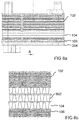
- FIGS. 2 to 5 each show a coolant-cooled condenser 102 in a stacked disc design, according to different embodiments of the present invention.
- One heat exchanger is shown in complete soldering with integrated collector. Different types of stack construction are also possible.
- the heat transfer takes place in a first part by stacked stacked disks, which are alternately flowed through by refrigerant and water or a glycol mixture.
- This first part is completed by a suitable part 204.
- a so-called base plate 204 In this case, by a so-called base plate 204.
- the base plate 204 is followed directly by a volume element 104, which serves for the storage of refrigerant.
- the volume element 104 may be open on both sides, as in the Figures 3 and 4 shown, or made open on one side, as in the Figures 2 and 5 is shown.
- the dimensions of the volume portion 104 may be less than, equal to, or greater than the stacked plate heat exchanger portion 102.
- the volume element 104 has at least one refrigerant inlet and one refrigerant outlet 206.
- the refrigerant can be introduced via the open side.
- the volume element 104 may have one or more channels for the further guidance of refrigerant and / or water or a glycol mixture, for example, to supply a subcooling path 106 with refrigerant or water or to represent a specific connection situation.
- the structure is also possible for alternative capacitor designs, such as flat tube packages or ribbed packages.
- the stacking disk is merely an exemplary embodiment, for example a stacked variant of extruded profiles and turbulence inserts is also possible.
- a filter and / or a desiccant in the volume element (collector) preservation of desired properties of the refrigerant is possible.
- the connections shown here on the water side and on the refrigerant side are to be understood as examples of the arrangement and can be arranged as desired.
- Fig. 2 shows a representation of an embodiment of an indirect capacitor 102 with integrated reservoir 104 (KOMO).
- the condenser 102 is configured by using stacking disks as the coolant-cooled condenser 102, that is, a component through which refrigerant and cooling water flow.
- the reservoir is designed as a volume component 104.
- Replacing an air cooled condenser with a coolant cooled condenser 102 provides new and different possibilities and conditions for integrating a header into the component. As a result, the number of connection points can be reduced and an attachment of the entire component in the engine compartment can be improved.
- the stack of stacking disks is bounded downwardly by a base plate 204.
- the base plate 204 at the same time closes off the volume element 104 in the direction of the condenser 102 in a fluid-tight manner and projects circumferentially over outer edges of the volume element 104.
- the volume element 104 is executed in this embodiment as a flow press, casting or diecasting with directly integrally integrated bottom. Through the bottom, a refrigerant outlet 206 protrudes downward from the volume element 104. From the condenser 102, two tubular water connections 208 lead to the right and left on an upper side for the supply and removal of cooling water upwards.
- the stacking disks have a quadrangular shape with rounded corners and have an upwardly embossed edge which closes a cavity in the stack between two stacking disks.
- Fig. 3 shows a view of a device for heat transfer according to an embodiment of the present invention.
- the illustration corresponds to Fig. 3 the representation in Fig. 2
- the volume element 104 is designed here as an extrusion or continuous casting. Therefore, another base plate 204 closes off the volume element 104.
- the base plate 204 is arranged on a side of the volume element 104 opposite the capacitor 102.
- Fig. 4 shows a side view of another device for heat transfer according to another embodiment of the present invention.
- this device has a subcooling element 106 which is arranged on the side of the further base plate 204 facing away from the volume element 104.
- the subcooling element 106 is constructed of stacking disks which are rotated 180 ° relative to the stacking disks of the condenser 102 about a longitudinal axis of the stacking disks.
- a refrigerant inlet 402 is shown, which is arranged on a side facing away from the volume element 104 side of the capacitor 102, protruding from the capacitor 102 console.
- the console essentially corresponds to the console for the refrigerant outlet 206, which protrudes from the supercooling element 106 in this exemplary embodiment on a side of the supercooling element 106 facing away from the volume element 104.
- the main opening of the refrigerant inlet 402 is here occupied by one of the water connections 208.
- the refrigerant inlet 402 is arranged diagonally opposite the refrigerant outlet 206.
- Fig. 5 shows a representation of a device for heat transfer according to an embodiment of the present invention, as shown in FIG Fig. 4 is shown.
- the volume element 104 as in Fig. 2 designed as extruded part, casting or as a die-cast with bottom. Therefore, the sub-cooling member 106 has no base plate 204 as a final element. The stacking discs of the subcooling member 106 are attached directly to the bottom of the volume member 104.
- the Figures 6a to 7b show two embodiments of a volume element 104 according to the approach presented here.
- the volume element 104 stiffening ribs 602 as in the FIGS. 6b to 7b shown, as well as having a curved print technically optimized outer shell.
- a thickness of the stiffening ribs may be smaller, equal to or greater than an outer wall thickness of the volume element.
- the height H of the volume element (in Fig. 7b ) depends on the external dimensions.
- the free internal volume may typically be between 0.0265 and 0.421 dm 3, and more preferably between 0.051 and 0.161 dm 3 .
- Fig. 6a Fig. 12 shows a bottom view of a bottom of a volume element 104 as part of an embodiment of the present invention.
- the bottom has an approximately rectangular shape.
- Lateral walls of the volume element 104 are formed wave-shaped.
- two orthogonal axes are drawn, representing the main directions of extension of the soil. Laterally offset to a longitudinal axis is a section AA recorded.
- Fig. 6b shows a section along the section AA Fig. 6a , The section is perpendicular to the bottom of the volume element 104.
- the bottom, two outer walls and three reinforcing ribs 602 are marked as cut surfaces by hatching.
- the reinforcing ribs 602 have the same spacings between one another and with the outer walls.
- FIG. 7a Figure 10 shows a view of a bottomless volume element 104 as part of an embodiment according to the present invention.
- the volume element 104 has an elongated rectangular outer contour. Perpendicular to the outer contour, the volume element 104 has stiffening ribs 602.
- the stiffening ribs 602 are evenly distributed symmetrically over the outer contour.
- Three stiffening ribs 602 perpendicular to a long side of the volume element 104 extend to an opposite long side.
- a middle of the three stiffening ribs 602 lies in a transverse axis of the volume element. Symmetrically with respect to a longitudinal axis of the volume element, the three stiffening ribs 602 each have a breakthrough offset laterally offset.
- the volume element 104 On short sides of the volume element 104 is located in each case one arranged in the longitudinal axis of the stiffening rib 602. Between the ribs, the outer contour has a curved shape.
- a section AA is corresponding to the section AA from Fig. 6a located.
- Fig. 7b shows a vertical section along the section AA through the volume element 104 from Fig. 7a , The cut corresponds to the cut Fig. 6b , In contrast to Fig. 6b the volume element 104 has no bottom.
- the outer contour and the stiffening ribs 602 have a height H.
- FIGS. 8a to 9b show two variants of a heat exchanger 102 in stacked disk design.
- the collector 104 is also made of stacked disks.
- To generate the volume also discs are used, between which a rib 802 or the like is arranged.
- the number of discs with ribs depends on the desired internal volume and the size of the disc.
- the disks can be flowed through with ribs 802 to create a collector 104 in single or multi-flow design.
- the ribs may be smooth, gilled, or staggered.
- To the volume element 104 then, as in the FIGS. 8a and 8b Shown again slices without additional ribs 802 to be installed.
- the rib thickness may be smaller than, equal to or greater than the stacking plate thickness.
- Fig. 8a shows an illustration of a device for heat transfer for a vehicle according to an embodiment of the present invention.
- the device shown essentially corresponds to a device as shown in the FIGS. 4 and 5 are shown.
- the volume element 104 is constructed of stacked disks with interposed ribs.
- the subcooling element 106 is composed of stacking disks which have the same orientation as the stacking disks of the condensation part 102 and the volume element 104.
- the subcooling element 106 terminates with a base plate 204.
- a section A is entered.
- the section A runs perpendicular to a main extension plane of the stacking disks through the condenser 102, the volume element 104 and the subcooling element 106.
- Fig. 8b shows the part of a section A along the section A from Fig. 8b
- the condenser 102 two turbulence elements are respectively arranged between two stacking disks.
- a rib 802 is arranged between two stacking disks.
- the volume element 104 consists of three superimposed planes of ribs 802 and stacking disks.
- two turbulence elements are each again arranged between two stacking disks.
- the ribs 802 have an angular wavy shape. Flattened highs and lows of the wavy shape are connected to the adjacent stack disks. Straight joints between the high points and the low points connect the stacking disks with each other and keep the stacking disks at a distance.
- Fig. 9a shows an illustration of a device for heat transfer for a vehicle according to an embodiment of the present invention.
- the representation corresponds to the representation in Fig. 8a , In contrast to Fig. 8a shows Fig. 9a no subcooling element.
- the volume element 104 terminates with a base plate 204.
- Fig. 9b shows a sectional view through a part of the device Fig. 9a , Because in Fig. 9a no subcooling element is shown, also has the sectional view in contrast to Fig. 8a no subcooling element. Otherwise, the sectional view corresponds essentially Fig. 8b , As a conclusion of the volume element, a section through the base plate 204 is shown.
- the Fig. 10a and 10b show two further embodiments of a device according to the invention, wherein for the sake of clarity, only the flow channels for the passage of the fluid 114 are shown.
- the subcooling element 106 according to Fig. 10a in this case has a first fourth flow channel 122 a, which is fluidically connected to a passage 150. Furthermore, the subcooling element 106 has a second fourth flow channel 122b, which is fluidically separated from the first fourth flow channel 122a.
- the second fourth flow channel 122b has a longer path in the subcooling element 106, as the first fourth flow channel.
- Fig. 10b It is also possible for the device to have a first second flow channel 112a and a second second flow channel 112b, the first second flow channel 112a being connected to a passage 150 and being fluidly separated from the second second flow channel 112b. Also in this embodiment, it is therefore possible to flow the device with a fluid 114 at different temperatures.
Description
- Die vorliegende Erfindung bezieht sich auf eine Vorrichtung zur Wärmeübertragung für ein Fahrzeug.
- Ein herkömmlicher Kondensator für Kältemittel in einem Fahrzeug ist über eine Leitung mit einem Vorratsbehälter für verflüssigtes Kühlmittel verbunden. Die Leitung weist Verbindungsstellen, wie Flansche, Verschraubungen und Dichtelemente zwischen Rohrstücken auf. Daher weist ein herkömmlicher Kondensator eine Vielzahl von potentiellen Leckstellen auf. Eine Vielzahl an Bauteilen und eine aufwendige Anbindung und Befestigung über Halter bedingen hohe Kosten und machen das gesamte Package unwirtschaftlich. Das Dokument
US 2006/053833 A1 offenbart eine Vorrichtung zur Wärmeübertragung für ein Fahrzeug gemäß dem Oberbegriff des Anspruchs 1. - Es ist die Aufgabe der vorliegenden Erfindung eine verbesserte Vorrichtung zur Wärmeübertragung für ein Fahrzeug zu schaffen.
- Diese Aufgabe wird durch eine Vorrichtung zur Wärmeübertragung für ein Fahrzeug gemäß dem Hauptanspruch gelöst.
- Der vorliegenden Erfindung liegt die Erkenntnis zugrunde, dass ein Vorratsbehälter für Kältemittel als Sammler unmittelbar in einen Kondensator integriert werden kann. Dadurch können kritische Verbindungsstellen in Leitungen entfallen, die anfällig für Undichtigkeiten sein können. Der Vorratsbehälter und der Kondensator können durch ein Fügeverfahren wie Schweißen oder Löten stoffschlüssig verbunden werden. Über eine entsprechende Gestaltung eines Übergangsbereichs zwischen den Bauteilen kann dann beispielsweise ein Abschlusselement des Kondensators gleichzeitig ein integraler Bestandteil des Vorratsbehälters sein. Um eine kompakte Bauweise zu realisieren ist es möglich, den Kondensator als indirekten Kondensator mit einem Kühlmittel wie beispielsweise Wasser oder einem Glykol-Wasser-Gemisch zu kühlen. Gegenüber einer Ausführung des Kondensators mit einem Wärmeübergang zwischen dem Kondensator und Luft ergibt sich ein kleinerer Wärmetauscher, da aufgrund einer höheren Wärmekapazität von Wasser und einem günstigeren Wärmeübergangskoeffizienten eine geringere Fläche für den Wärmeübergang notwendig ist. Dadurch lässt sich der Kondensator näher an anderen Komponenten eines Kältemittelkreislaufs platzieren. Durch den geringeren Raumbedarf lässt sich der Vorratsbehälter in das Kondensatorbauteil integrieren. Eine geringere Anzahl verbauter Komponenten bedingt geringere Herstellungskosten, sowie geringere Montagekosten. Ein Entfall von Verbindungsflanschen und Leitungen führt zu einer verbesserten Dichtheit.
- Vorteilhafterweise kann durch eine direkte Kombination eines flüssigkeitsgekühlten Kondensators mit einem Volumenelement, innerhalb eines einstückigen Bauteils, eine kompaktere Bauform erzielt werden, die hinsichtlich eines Bauraums optimiert ist. Dadurch ist auch ein Entfall von Flanschen und Verbindungsbauteilen möglich. Durch eine Komplettlötung, die zu einem Bauteil und somit dem Entfall von Verbindungsflanschen und Rohrleitungen führt, ist ein Kostenvorteil durch geringere Materialkosten realisierbar. Auch kann eine verbesserte Dichtheit durch einen Entfall von O-Ringen und durch eine Verringerung potentieller Leckstellen erreicht werden.
- Die vorliegende Erfindung schafft eine Vorrichtung zur Wärmeübertragung für ein Fahrzeug, mit folgenden Merkmalen:
- einem Kondensator zur Kondensation eines Kältemittels, mit einem ersten Strömungskanal zur Leitung des Kältemittels und einem zweiten Strömungskanal zur Leitung eines Fluids, wobei die Strömungskanäle ausgebildet sind, um Wärmeenergie von dem Kältemittel auf das Fluid zu übertragen; und
- einem Volumenelement, das zur Bevorratung des Kältemittels fluidisch mit dem ersten Strömungskanal verbunden ist, wobei das Volumenelement stoffschlüssig mit dem Kondensator verbunden ist.
- Unter einem Kondensator kann ein Wärmetauscher verstanden werden, der dazu ausgebildet ist, ein Fluid unter Energieentzug von einer gasförmigen Phase in eine zumindest teilweise flüssige Phase überzuführen. Dazu kann beispielsweise ein weiteres Fluid im Kondensator die entzogene Energie aufnehmen. Das weitere Fluid kann eine Flüssigkeit, wie Wasser mit oder ohne Additive, sein. Das weitere Fluid kann ebenso ein Gas wie Luft oder Kohlendioxid sein. Der Kondensator kann zumindest zwei Strömungskanäle aufweisen. Ein Strömungskanal kann gegenüber dem anderen Strömungskanal und/oder der Umwelt fluidundurchlässig sein. Die Strömungskanäle können in unmittelbarer Nachbarschaft zueinander angeordnet sein, so dass ein Energiefluss in Form von Wärme zwischen den Strömungskanälen einen geringen Wärmewiderstand überwinden muss. Die Strömungskanäle können dazu aus einem Material mit guter Wärmeleitfähigkeit, wie beispielsweise Kupfer, Aluminium, Kunststoff oder Eisenwerkstoffen bestehen. In den Strömungskanälen können Einbauten angeordnet sein, die den Wärmeübergang zwischen dem Fluid und einer Grenzfläche des Strömungskanals verbessern. Beispielsweise können Turbulenzbleche oder andere turbulenzerzeugende Strukturen in den Strömungskanälen angeordnet sein. In den ersten Strömungskanal kann ein Kältemittel eingebracht werden. Das Kältemittel kann beispielsweise bei niedriger Temperatur und niedrigem Druck Wärme aufnehmen und bei höherer Temperatur und höherem Druck Wärme abgeben. In den zweiten Strömungskanal kann ein Kühlmittel eingebracht werden. Das Kühlmittel kann beispielsweise Kühlwasser sein. Das Kühlmittel kann Wärme abtransportieren. Unter einem Volumenelement kann ein Vorratsbehälter verstanden werden. Das Volumenelement kann gegenüber der Umgebung fluiddicht ausgeführt sein. Das Volumenelement kann zumindest zwei Öffnungen aufweisen, durch die das Kältemittel im ersten Strömungskanal ein- oder ausströmen kann. Das Volumenelement kann mit dem Kondensator verlötet, geklebt oder verschweißt sein. Die Vorrichtung kann mehrere Anschlüsse aufweisen. Durch einen der Anschlüsse kann das Kältemittel in den ersten Strömungskanal des Kondensators einströmen, durch einen zweiten der Anschlüsse kann das Kältemittel aus der Vorrichtung ausströmen. Durch einen dritten Anschluss kann das Kühlmittel in den zweiten Strömungskanal einströmen, und durch einen vierten Anschluss kann das Kühlmittel aus dem zweiten Strömungskanal ausströmen.
- Gemäß einer weiteren Ausführungsform der vorliegenden Erfindung umfasst die Vorrichtung eine Grundplatte, die zwischen dem Kondensator und dem Volumenelement angeordnet ist, wobei eine erste Seite der Grundplatte eine Grundfläche des Kondensators ausbildet, und eine zweite Seite der Grundplatte eine Deckfläche des Volumenelements ausbildet. Unter einer Grundplatte kann ein Zwischenelement verstanden werden. Eine Erstreckungsebene einer Grundfläche des Kondensators kann mit einer Erstreckungsebene einer Deckfläche des Volumenelements übereinstimmen, das heißt, dass zumindest ein Teil der Grundfläche des Kondensators durch das Zwischenelement gebildet wird. Auch kann die Grundfläche direkt angrenzend an die Deckfläche angeordnet sein. Die Grundplatte kann auf einer ersten Seite Bestandteil des Kondensators sein und auf einer zweiten, gegenüberliegenden Seite Bestandteil des Volumenelements sein. Die Grundplatte kann das Volumenelement fluiddicht von dem zweiten Strömungskanal trennen. Durch einen gestapelten Aufbau der Vorrichtung kann eine Fertigung besonders effizient erfolgen.
- Ferner kann das Volumenelement zumindest eine Durchleitung zur Leitung des Fluids oder des Kältemittels durch das Volumenelement aufweisen, wobei die Durchleitung mit dem ersten oder zweiten Strömungskanal fluidisch verbunden ist. Eine Durchleitung im Sinne der Erfindung kann beispielsweise ein Rohr oder ein oder mehrere Kanäle sein. Die Durchleitung kann insbesondere das Fluid aus dem zweiten Strömungskanal durch das Volumenelement leiten, wenn der Strömungskanal auf einer Seite des Volumenelements angeschlossen ist, die von einer Seite des Volumenelements abweicht, auf der sich der Kondensator befindet. Dadurch können unterschiedliche Anschlusssituationen im Fahrzeug bei geringstem Bauraumvolumen bewältigt werden.
- Entsprechend einer weiteren Ausführungsform der vorliegenden Erfindung kann die Vorrichtung ein Unterkühlungselement, mit einem dritten Strömungskanal zur Leitung des Kältemittels und einem vierten Strömungskanal zur Leitung des Fluids aufweisen, wobei der dritte Strömungskanal zur Unterkühlung des Kühlmittels aus dem Volumenelement fluidisch mit dem Volumenelement verbunden ist, und wobei der vierte Strömungskanal fluidisch mit dem zweiten Strömungskanal verbunden sein kann, wobei das Unterkühlungselement stoffschlüssig mit dem Volumenelement verbunden ist. Unter einem Unterkühlungselement kann ein Wärmetauscher verstanden werden. In dem Unterkühlungselement kann dem kondensierten, in flüssiger Phase vorliegenden Kältemittel weitere Wärmeenergie entzogen werden. Dadurch kann eine Temperatur des flüssigen Kältemittels weiter unter eine Verdampfungstemperatur des Kältemittels abgesenkt werden. Ein dritter Strömungskanal kann von dem Volumenelement zu einem Anschluss für das Kältemittel führen. Ein vierter Strömungskanal kann das Fluid so führen, dass es Wärmeenergie aus dem Kältemittel entziehen kann. Der dritte und vierte Strömungskanal können voneinander fluiddicht getrennt sein. Durch ein Unterkühlungselement kann das Kältemittel eine größere Wärmeaufnahmekapazität erreichen, als direkt nach der Kondensation im Kondensator.
- In einer weiteren Ausführungsform kann das Unterkühlungselement auf einer dem Kondensator gegenüberliegenden Seite des Volumenelements angeordnet sein. Alternativ können das Unterkühlungselement und der Kondensator auf der gleichen Seite des Volumenelements angeordnet sein. Durch diese Anordnung kann das Kältemittel zuerst durch den Kondensator in das Volumenelement und anschließend aus dem Volumenelement durch das Unterkühlungselement fließen. Dabei können der Kondensator und das Unterkühlungselement voneinander beabstandet angeordnet sein. Der Kondensator und ebenfalls oder alternativ das Unterkühlungselement können mehrere verschachtelte Plattenelemente aufweisen. Dabei können die Strömungskanäle durch die Plattenelemente gebildet werden. Ferner können der Kondensator und/oder das Unterkühlungselement Turbulenzelemente aufweisen. Unter einem Plattenelement kann ein vorwiegend in einer Haupterstreckungsebene ausgeformtes Bauteil, wie eine Stapelscheibe verstanden werden. Das Plattenelement kann Erhebungen, Vertiefungen und/oder Durchbrüche aufweisen, die ausgebildet sind, um ein erstes Plattenelement mit zumindest einem weiteren Plattenelement zu verbinden und dabei zumindest zwei Strömungskanäle auszubilden. Unter einem Turbulenzelement kann ein Bauteil verstanden werden, dass durch Durchbrüche, Einschnitte und/oder Ausprägungen ausgebildet ist, um in einem vorbeiströmenden Fluid Wirbel zu erzeugen und eine turbulente Strömung hervorzurufen. Dabei kann das Turbulenzelement innerhalb eines oder mehrerer Strömungskanäle angeordnet sein. Mehrere Plattenelemente können gegengleich ineinander verschachtelt werden, um die Strömungskanäle auszubilden. Dabei können der Kondensator und/oder das Unterkühlungselement das Fluid von dem Kältemittel getrennt leiten. Durch Stapelscheibenbauweise lässt sich eine einfache, wirtschaftliche Fertigungsmethode realisieren, da die Stapelscheiben selbstzentrierend sein können und keine beweglichen Teile in dem Stapel angeordnet sind. Ein Stapel Stapelscheiben lässt sich mit angrenzendem Volumenelement und auch mit Unterkühlungselement in einem Arbeitsgang komplett löten, kleben oder schweißen.
- In einer zusätzlichen Ausführungsform der vorliegenden Erfindung kann das Volumenelement aus weiteren Plattenelementen und zumindest einem eingefügten Rippenelement aufgebaut sein, wobei das Rippenelement ausgeformt ist, um vergrößerte Strömungskanäle zur Bevorratung des Kältemittels auszubilden. Auch das Volumenelement lässt sich aus Stapelscheiben aufbauen. Dafür können die Turbulenzelemente durch zumindest ein Rippenelement ausgetauscht werden. Das Rippenelement kann ein Abstandhalter sein, der zwischen Rippen des Abstandhalters mit den Plattenelementen Hohlräume ausbilden kann. Die Hohlräume können gegenüber der Umwelt fluiddicht abgeschlossen sein. Die Rippen können beispielsweise versetzt, durchgehend oder mit Kiemen ausgebildet sein. Durch den Aufbau des Volumenelements aus Stapelscheiben und Rippenelementen kann die Herstellung der Vorrichtung weiter vereinfacht und rationalisiert werden.
- Gemäß einer weiteren Ausführungsform der vorliegenden Erfindung kann das Volumenelement im Inneren zumindest zwei Versteifungsrippen aufweisen, wobei eine äußere Hülle des Volumenelements zwischen den Versteifungsrippen eine nach außen gewölbte Form aufweist. Das Volumenelement kann auch ganz oder teilweise aus einem Stranggussteil oder Gussteil bestehen. Dadurch kann eine Wandstärke des Volumenelements einem Betriebsdruck im Volumenelement angepasst werden. Die Wandstärke kann durch Verstärkungsrippen im Volumenelement und/oder druckoptimierter Wandgestaltung minimiert werden. Eine nach außen gewölbte Form kann bei gleicher Wandstärke höherem Druck widerstehen, als eine gerade Form.
- Entsprechend einer weiteren Ausführungsform umfasst das Volumenelement ein Mittel zum Filtern des Kältemittels und zusätzlich oder alternativ ein Mittel zum Trocknen oder Entwässern des Kältemittels. Dadurch kann eine gleichbleibende Qualität des Kältemittels sichergestellt werden. Das Mittel zum Filtern des Kältemittels und/oder ein Mittel zum Trocknen oder Entwässern des Kältemittels kann alternativ auch an dem Volumenelement angebracht sein.
- Gemäß einer Ausführungsform kann das Volumenelement ein im Betrieb freies Innenvolumen zwischen 0,3 dm3 und 0,01 dm3 aufweisen. Dadurch kann eine für das Kühlsystem geeignete Flüssigkeitsmenge im Volumenelement bevorratet werden. Unter dem Merkmal "ein im Betrieb freies Volumen" ist erfindungsgemäß das Volumen des Volumenelementes abzüglich etwaiger Einbauten wie Mittel zum Filtern, Trocknen, etc. zu verstehen,
- Unabhängig davon kann es erfindungsgemäß von Vorteil sein, wenn die Vorrichtung zur Wärmeübertragung für ein Fahrzeug folgende Merkmale aufweist: ein Unterkühlungselement zur Unterkühlung eines Kältemittels mit zumindest einem dritten Strömungskanal zur Leitung des Kältemittels und zumindest einem vierten Strömungskanal zur Leitung eines Fluids, wobei die Strömungskanäle ausgebildet sind, um Wärmeenergie von dem Kältemittel auf das Fluid zu übertragen und einem Volumenelement, das zur Bevorratung des Kältemittels fluidisch mit dem dritten Strömungskanal verbunden ist, wobei das Volumenelement stoffschlüssig mit dem Unterkühlungselement verbunden ist. Gemäß dieser Ausführungsform bilden also das Unterkühlungselement und das Volumenelement eine Baueinheit, wobei der Kondensator als separates Bauteil ausgebildet ist und beispielsweise über Leitungen fluidisch mit dem Volumenelement verbunden ist.
- Vorteilhafte Ausführungsbeispiele der vorliegenden Erfindung werden nachfolgend Bezug nehmend auf die beiliegenden Zeichnungen näher erläutert. Es zeigen:
- Fig. 1a bis 1d
- schematische Darstellungen mehrerer Ausführungsbeispiele einer Vorrichtung zur Wärmeübertragung gemäß dem hier vorgestellten Ansatz;
- Fig. 2 und 3
- räumliche Darstellungen zweier Ausführungsbeispiele eines Kondensators mit einem direkt verbundenen Volumenelement gemäß dem hier vorgestellten Ansatz;
- Fig. 4 und 5
- Seitenansichten zweier Ausführungsbeispiele eines Kondensators mit einem direkt verbundenen Volumenelement und einem direkt verbundenen Unterkühlungselement gemäß dem hier vorgestellten Ansatz;
- Fig. 6a bis 7b
- Draufsichten und Schnitte zweier Ausführungsbeispiele eines Bestandteils eines Volumenelements gemäß dem hier vorgestellten Ansatz;
- Fig. 8a und 8b
- eine Seitenansicht und einen Teilschnitt eines Kondensators mit einem direkt verbundenen Volumenelement aus Stapelplatten gemäß einem Ausführungsbeispiel der vorliegenden Erfindung; und
- Fig. 9a und 9b
- eine Seitenansicht und einen Teilschnitt eines Kondensators mit einem direkt verbundenen Volumenelement aus Stapelplatten und einem direkt verbundenen Unterkühlungselement gemäß einem Ausführungsbeispiel der vorliegenden Erfindung.
- Fig. 10a und 10b
- zwei weitere Ausführungsbeispiele einer erfindungsgemäßen Vorrichtung.
- In der nachfolgenden Beschreibung der bevorzugten Ausführungsbeispiele der vorliegenden Erfindung werden für die in den verschiedenen Zeichnungen dargestellten und ähnlich wirkenden Elemente gleiche oder ähnliche Bezugszeichen verwendet, wobei eine wiederholte Beschreibung dieser Elemente weggelassen wird.
- Die
Figuren 1a bis 1d stellen in unterschiedlichen Ausführungsbeispielen der vorliegenden Erfindung schematisch Kerngesichtspunkte der Erfindung dar. Kern ist jeweils ein kühlmittelgekühlter Kondensator (iCond), der aus einem Kondensationsteil 102 und einem mit dem Kondensationsteil 102 unlösbar verbunden Sammler 104 als Volumenkörper besteht. Optional kann, wie in denFiguren 1b
und 1c gezeigt, auch ein Unterkühlungsteil 106 unlösbar oder auch lösbar mit dem Kondensationsteil 102 oder dem Sammler 104 verbunden sein. Die Einbaulage des Unterkühlungsteils kann hierbei beliebig sein. Der Sammler 104 und das Unterkühlungsteil 106 können, wie inFig. 1d beispielhaft gezeigt, gleiche oder unterschiedliche Abmessungen aufweisen. -
Fig. 1a zeigt ein Blockschaltbild einer Vorrichtung zur Wärmeübertragung für ein Fahrzeug gemäß einem Ausführungsbeispiel der vorliegenden Erfindung. Ein Kondensator 102 ist mit einem Volumenelement 104 stoffschlüssig verbunden. Der Kondensator weist zumindest einen ersten Strömungskanal 108 zur Leitung eines Kältemittels 110, sowie zumindest einen zweiten Strömungskanal 112 zur Leitung eines Fluids 114 auf. Der erste Strömungskanal 108 ist gegen den zweiten Strömungskanal 112 fluiddicht abgedichtet. Der erste Strömungskanal weist eine Einflussöffnung und eine Ausflussöffnung auf, wobei die Ausflussöffnung in das Volumenelement 104 mündet. Damit ist die Ausflussöffnung des ersten Strömungskanals 108 auch eine Einflussöffnung des Volumenelements 104. Das Volumenelement 104 ist als Vorratsbehälter für das Kältemittel 110 vorgesehen. Das Volumenelement 104 weist ebenfalls eine Ausflussöffnung für das Kältemittel 110 auf. Der zweite Strömungskanal 112 im Kondensator 102 weist einen Einlauf für das Fluid 114, sowie einen Auslauf für das Fluid 114 auf. Im Kondensator 102 kann Wärmeenergie von dem Kältemittel 110 auf das Fluid 114 übertragen werden. -
Fig. 1b zeigt eine Prinzipskizze einer Vorrichtung zur Wärmeübertragung für ein Fahrzeug als Ausführungsbeispiel der vorliegenden Erfindung. Wie inFig. 1a ist ein Kondensator 102 mit einem Volumenelement 104 stoffschlüssig verbunden. Im Unterschied zuFig. 1a ist auf einer dem Kondensator 102 gegenüberliegenden Seite des Volumenelements 104 ein Unterkühlungselement 106 angeordnet. Das Unterkühlungselement 106 ist mit dem Volumenelement 104 ebenfalls stoffschlüssig verbunden. Wie inFig. 1b gezeigt, ist der Kondensator 102 oberhalb des Volumenelements 104 angeordnet und das Unterkühlungselement 106 ist unterhalb des Volumenelements 104 angeordnet. Dadurch kann kondensiertes Kältemittel durch die Schwerkraft aus dem Kondensator 102 in das Volumenelement 104 fließen und dort bevorratet werden. Aus dem Volumenelement 104 kann das flüssige Kältemittel durch die Schwerkraft in das Unterkühlungselement 106 fließen und dort weiter abgekühlt werden. Der Kondensator 102, das Volumenelement 104 und das Unterkühlungselement 106 können jeweils die gleiche Querschnittsfläche aufweisen. -
Fig. 1c zeigt eine Prinzipskizze einer weiteren Vorrichtung zur Wärmeübertragung für ein Fahrzeug als weiteres Ausführungsbeispiel der vorliegenden Erfindung. Wie inFig. 1b ist ein Kondensator 102 zumindest mit einem Volumenelement 104 und/oder einem Unterkühlungselement 106 stoffschlüssig verbunden. Im Unterschied zuFig. 1b sind der Kondensator 102 und das Unterkühlungselement 106 auf der gleichen Seite des Volumenelements 104 angeordnet. Durch die Anordnung des Unterkühlelements 106 auf der gleichen Seite des Volumenelements 104, wie der Kondensator 102, können besondere Bauraum-Voraussetzungen berücksichtigt werden. Weiterhin ergibt sich die Möglichkeit, eine größere Menge an Kältemittel zu bevorraten, da das Volumenelement 104 im Vergleich zu dem Kondensator 102 und dem Unterkühlungselement 106 eine größere Abmessung aufweist. -
Fig. 1d zeigt eine Prinzipskizze einer Vorrichtung zur Wärmeübertragung für ein Fahrzeug als weiteres Ausführungsbeispiel der vorliegenden Erfindung. Die gezeigte Anordnung folgt im Wesentlichen der Anordnung ausFig. 1b , mit einem Kondensator 102, einem Volumenelement 104 und einem Unterkühlungselement 106, die stoffschlüssig miteinander verbunden sind, wobei der Kondensator 102 und das Unterkühlungselement 106 auf gegenüberliegenden Seiten des Volumenelements 104 angeordnet sind. Im Unterschied zuFig. 1b weisen die Einzelbestandteile der Vorrichtung unterschiedliche Dimensionen auf. So weist das Volumenelement 104 geringere Abmessungen als der Kondensator 102 auf. Das Unterkühlungselement 106 weist wiederum geringere Abmessungen als das Volumenelement 104 auf. Gemäß diesem Ausführungsbeispiel beziehen sich die geringeren Abmessungen jeweils auf die Höhe und Grundfläche der jeweiligen Einzelbestandteile. Damit können die Einzelbestandteile an spezifische Betriebsbedingungen, Bauraum- und Leistungsanforderungen angepasst werden. - Die
Figuren 2 bis 5 zeigen jeweils einen kühlmittelgekühlten Kondensator 102 in Stapelscheibenbauweise, gemäß unterschiedlichen Ausführungsbeispielen der vorliegenden Erfindung. Dabei ist je ein Wärmeübertrager in Komplettlötung mit integriertem Sammler dargestellt. Von der Stapelbauweise abweichende Bauformen sind ebenso möglich. Der Wärmeübergang erfolgt in einem ersten Teil durch geschichtete Stapelscheiben, die abwechselnd mit Kältemittel und Wasser oder einem Glykolgemisch durchströmt werden. Dieser erste Teil wird durch ein geeignetes Teil 204 abgeschlossen. In diesem Fall durch eine so genannte Grundplatte 204. An die Grundplatte 204 schließt sich direkt ein Volumenelement 104 an, welches zur Kältemittelbevorratung dient. Das Volumenelement 104 kann beidseitig offen, wie in denFiguren 3 und4 dargestellt, oder einseitig offen hergestellt werden, wie es in denFiguren 2 und5 dargestellt ist. Die Abmessungen des Volumenteiles 104 können kleiner, gleich oder größer als der Stapelscheiben-Wärmeübertragerteil 102 sein. Das Volumenelement 104 weist zumindest einen Kältemitteleintritt und einen Kältemittelaustritt 206 auf. Dabei kann der Kältemitteleintritt über die offene Seite erfolgen. Zusätzlich kann das Volumenelement 104 ein oder mehrere Kanäle zur weiteren Führung von Kältemittel und/oder Wasser bzw. einem Glykolgemisch aufweisen, um beispielsweise eine Unterkühlstrecke 106 mit Kältemittel oder Wasser zu versorgen oder eine spezielle Anschlusssituation darzustellen. Prinzipiell ist der Aufbau auch für alternative Kondensatorbauweisen, wie beispielsweise Flachrohrpakete oder Rippenpakete möglich. Die Stapelscheibe ist lediglich ein Ausführungsbeispiel, z.B. ist auch eine gestapelte Variante von extrudierten Profilen und Turbulenzeinlagen möglich. Durch eine zusätzliche Integration eines Filters und/oder eines Trockenmittels in das Volumenelement (Sammler) ist eine Erhaltung von gewünschten Eigenschaften des Kältemittels möglich. Die hier wasser- und kältemittelseitig dargestellten Anschlüsse sind von der Anordnung beispielhaft zu verstehen und können beliebig angeordnet sein. -
Fig. 2 zeigt eine Darstellung eines Ausführungsbeispiels eines indirekten Kondensators 102 mit integriertem Vorratsbehälter 104 (KOMO). Der Kondensator 102 ist unter Verwendung von Stapelscheiben als kühlmittelgekühlter Kondensator 102, d.h. ein Bauteil, das mit Kältemittel und Kühlwasser durchströmt wird, ausgeführt. Der Vorratsbehälter ist als Volumenbauteil 104 ausgeführt. Durch den Ersatz eines luftgekühlten Kondensators durch einen kühlmittelgekühlten Kondensator 102 ergeben sich neue und andere Möglichkeiten und Bedingungen zur Integration eines Sammlers in das Bauteil. Dadurch kann die Zahl von Verbindungsstellen reduziert werden und eine Anbringung des gesamten Bauteiles im Motorraum verbessert werden. Wie inFig. 2 dargestellt, wird der Stapel von Stapelscheiben nach unten von einer Grundplatte 204 begrenzt. Die Grundplatte 204 verschließt gleichzeitig das Volumenelement 104 in Richtung des Kondensators 102 fluiddicht und steht über äußere Kanten des Volumenelements 104 umlaufend über. Das Volumenelement 104 ist in diesem Ausführungsbeispiel als Fließpressteil, Gussteil oder Druckgussteil mit direkt einstückig integriertem Boden ausgeführt. Durch den Boden ragt ein Kältemittelaustritt 206 nach unten aus dem Volumenelement 104. Aus dem Kondensator 102 führen rechts und links auf einer Oberseite zwei rohrförmige Wasseranschlüsse 208 zur Zu- und Abfuhr von Kühlwasser nach oben hinaus. Die Stapelscheiben haben eine viereckige Form mit abgerundeten Ecken und weisen einen nach oben geprägten Rand auf, der einen Hohlraum im Stapel zwischen zwei Stapelscheiben abschließt. -
Fig. 3 zeigt eine Ansicht einer Vorrichtung zur Wärmeübertragung gemäß einem Ausführungsbeispiel der vorliegenden Erfindung. Im Wesentlichen entspricht die Darstellung inFig. 3 der Darstellung inFig. 2 . Im Unterschied zuFig. 2 ist das Volumenelement 104 hier als Extrusions- oder Stranggussteil ausgeführt. Daher schließt eine weitere Grundplatte 204 das Volumenelement 104 ab. Die Grundplatte 204 ist auf einer, dem Kondensator 102 gegenüberliegenden Seite des Volumenelements 104 angeordnet. -
Fig. 4 zeigt eine Seitenansicht einer weiteren Vorrichtung zur Wärmeübertragung gemäß einem weiteren Ausführungsbeispiel der vorliegenden Erfindung. Zusätzlich zur Vorrichtung inFig. 3 weist diese Vorrichtung ein Unterkühlelement 106 auf, das an der, vom Volumenelement 104 abgewandten Seite der weiteren Grundplatte 204 angeordnet ist. Das Unterkühlelement 106 ist aus Stapelscheiben aufgebaut, die gegenüber den Stapelscheiben des Kondensators 102 um 180° um eine Längsachse der Stapelscheiben gedreht sind. Desweiteren ist ein Kältemitteleinlauf 402 dargestellt, der an einer, vom Volumenelement 104 abgewandten Seite des Kondensators 102, aus dem Kondensator 102 herausragenden Konsole angeordnet ist. Die Konsole entspricht im Wesentlichen der Konsole für den Kältemittelaustritt 206, der in diesem Ausführungsbeispiel an einer, vom Volumenelement 104 abgewandten Seite des Unterkühlungselements 106 aus dem Unterkühlungselement 106 herausragt. Die Hauptöffnung des Kältemitteleinlaufs 402 ist hier von einem der Wasseranschlüsse 208 belegt. Dabei ist der Kältemitteleinlauf 402 dem Kältemittelaustritt 206 diagonal gegenüber angeordnet. -
Fig. 5 zeigt eine Darstellung einer Vorrichtung zur Wärmeübertragung gemäß einem Ausführungsbeispiel der vorliegenden Erfindung, wie sie inFig. 4 dargestellt ist. Im Gegensatz zuFig. 4 ist das Volumenelement 104 wie inFig. 2 als Fließpressteil, Gussteil oder als Druckgussteil mit Boden ausgeführt. Daher weist das Unterkühlungselement 106 keine Grundplatte 204 als abschließendes Element auf. Die Stapelscheiben des Unterkühlungselements 106 sind direkt am Boden des Volumenelements 104 befestigt. - Die
Figuren 6a bis 7b zeigen zwei Ausführungsbeispiele für ein Volumenelement 104 gemäß dem hier vorgestellten Ansatz. Zur besseren Drucksteifigkeit kann das Volumenelement 104 Versteifungsrippen 602, wie in denFiguren 6b bis 7b gezeigt, sowie eine geschwungene drucktechnisch optimierte äußere Hülle aufweisen. Eine Dicke der Versteifungsrippen kann kleiner, gleich oder größer einer äußeren Wandstärke des Volumenelementes betragen. Die Bauhöhe H des Volumenelements (inFig. 7b ) ist abhängig von den Außenabmessungen. Das freie Innenvolumen kann typischerweise zwischen 0,0265 und 0,421 dm3 und besonders bevorzugt zwischen 0,051 und 0,161 dm3 liegen. -
Fig. 6a zeigt eine Untersicht auf einen Boden eines Volumenelements 104 als Teil eines Ausführungsbeispiels der vorgestellten Erfindung. Der Boden weist eine näherungsweise rechteckige Form auf. Seitliche Wände des Volumenelements 104 sind wellenförmig ausgeformt. In die Untersicht sind zwei orthogonale Achsen eingezeichnet, die Haupterstreckungsrichtungen des Bodens repräsentieren. Seitlich zu einer Längsachse versetzt ist ein Schnittverlauf A-A eingetragen. -
Fig. 6b zeigt einen Schnitt entlang des Schnittverlaufs A-A ausFig. 6a . Der Schnitt liegt senkrecht zum Boden des Volumenelements 104. Als Schnittflächen durch eine Schraffur markiert sind der Boden, zwei Außenwände und drei Verstärkungsrippen 602. Die Verstärkungsrippen 602 weisen untereinander und zu den Außenwänden gleiche Abstände auf. -
Fig. 7a zeigt eine Ansicht eines Volumenelements 104 ohne Boden als Teil eines Ausführungsbeispiels gemäß der vorliegenden Erfindung. Das Volumenelement 104 weist eine längliche rechteckige Außenkontur auf. Rechtwinklig von der Außenkontur weist das Volumenelement 104 Versteifungsrippen 602 auf. Die Versteifungsrippen 602 sind gleichmäßig symmetrisch über die Außenkontur verteilt. Drei Versteifungsrippen 602 senkrecht zu einer langen Seite des Volumenelements 104 erstrecken sich bis zu einer gegenüberliegenden langen Seite. Eine Mittlere der drei Versteifungsrippen 602 liegt in einer Querachse des Volumenelements. Symmetrisch zu einer Längsachse des Volumenelements weisen die drei Versteifungsrippen 602 je einen gegengleich seitlich versetzten Durchbruch auf. An kurzen Seiten des Volumenelements 104 befindet sich je eine in der Längsachse angeordnete Versteifungsrippe 602. Zwischen den Rippen weist die Außenkontur eine geschwungene Form auf. Ein Schnittverlauf A-A ist entsprechend dem Schnittverlauf A-A ausFig. 6a eingezeichnet. -
Fig. 7b zeigt einen senkrechten Schnitt entlang des Schnittverlaufs A-A durch das Volumenelement 104 ausFig. 7a . Der Schnitt entspricht dem Schnitt ausFig. 6b . Im Gegensatz zuFig. 6b weist das Volumenelement 104 keinen Boden auf. Die Außenkontur und die Versteifungsrippen 602 weisen eine Höhe H auf. - Die
Figuren 8a bis 9b zeigen zwei Varianten eines Wärmeübertragers 102 in Stapelscheibenbauweise. Der Sammler 104 besteht ebenfalls aus Stapelscheiben. Zur Generierung des Volumens werden ebenfalls Scheiben verwendet, zwischen denen eine Rippe 802 oder ähnliches angeordnet ist. Die Anzahl der Scheiben mit Rippen ist abhängig vom gewünschten Innenvolumen und der Scheibengröße. Hierbei können die Scheiben mit Rippen 802 zur Schaffung eines Sammlers 104 in ein- oder mehrflutiger Bauweise durchströmt werden. Die Rippen können beispielsweise glatt, mit Kiemen ausgestellt oder versetzt ausgeführt sein. An das Volumenelement 104 anschließend können, wie in denFiguren 8a und 8b gezeigt, wieder Scheiben ohne zusätzliche Rippen 802 verbaut sein. Die Rippendicke kann kleiner, gleich oder größer der Stapelscheibendicke sein. -
Fig. 8a zeigt eine Darstellung einer Vorrichtung zur Wärmeübertragung für ein Fahrzeug gemäß einem Ausführungsbeispiel der vorliegenden Erfindung. Die gezeigte Vorrichtung entspricht im Wesentlichen einer Vorrichtung, wie sie in denFiguren 4 und 5 abgebildet sind. Im Gegensatz zu denFiguren 4 und 5 ist das Volumenelement 104 aus Stapelscheiben mit zwischengefügten Rippen aufgebaut. Desweiteren ist das Unterkühlungselement 106 aus Stapelscheiben zusammengesetzt, die die gleiche Ausrichtung aufweisen, wie die Stapelscheiben des Kondensationsteils 102 und des Volumenelements 104. Das Unterkühlungselement 106 schließt mit einer Grundplatte 204 ab. In die Darstellung ist ein Schnittverlauf A eingetragen. Der Schnittverlauf A verläuft senkrecht zu einer Haupterstreckungsebene der Stapelscheiben durch den Kondensator 102, das Volumenelement 104 und das Unterkühlungselement 106. -
Fig. 8b zeigt den Teil eines Schnitts A entlang des Schnittverlaufs A ausFig. 8b . Im Kondensator 102 sind zwischen zwei Stapelscheiben jeweils zwei Turbulenzelemente angeordnet. Im Volumenelement 104 ist zwischen zwei Stapelscheiben je eine Rippe 802 angeordnet. Das Volumenelement 104 besteht aus drei übereinander liegenden Ebenen aus Rippen 802 und Stapelscheiben. Im Unterkühlungselement 106 sind erneut zwischen zwei Stapelscheiben jeweils zwei Turbulenzelemente angeordnet. Die Rippen 802 weisen eine eckig-wellige Form auf. Abgeflachte Hochpunkte und Tiefpunkte der welligen Form sind mit den angrenzenden Stapelscheiben verbunden. Geradlinige Verbindungsteile zwischen den Hochpunkten und den Tiefpunkten verbinden die Stapelscheiben untereinander und halten die Stapelscheiben auf Abstand. -
Fig. 9a zeigt eine Darstellung einer Vorrichtung zur Wärmeübertragung für ein Fahrzeug gemäß einem Ausführungsbeispiel der vorliegenden Erfindung. Die Darstellung entspricht der Darstellung inFig. 8a . Im Gegensatz zuFig. 8a zeigtFig. 9a kein Unterkühlungselement. Das Volumenelement 104 schließt mit einer Grundplatte 204 ab. -
Fig. 9b zeigt eine Schnittdarstellung durch einen Teil der Vorrichtung ausFig. 9a . Da inFig. 9a kein Unterkühlungselement dargestellt ist, weist auch die Schnittdarstellung im Gegensatz zuFig. 8a kein Unterkühlungselement auf. Sonst entspricht die Schnittdarstellung im WesentlichenFig. 8b . Als Abschluss des Volumenelements ist ein Schnitt durch die Grundplatte 204 gezeigt. - Die
Fig. 10a und10b zeigen zwei weitere Ausführungsbeispiele einer erfindungsgemäßen Vorrichtung, wobei der Übersichtlichkeit halber lediglich die Strömungskanäle zur Leitung des Fluids 114 dargestellt sind. Das Unterkühlungselement 106 gemäßFig. 10a weist hierbei einen ersten vierten Strömungskanal 122a auf, der fluidisch mit einer Durchleitung 150 verbunden ist. Ferner weist das Unterkühlungselement 106 einen zweiten vierten Strömungskanal 122b auf, der fluidisch vom ersten vierten Strömungskanal 122a getrennt ist. Hierbei weist der zweite vierte Strömungskanal 122b eine längere Wegstrecke im Unterkühlungselement 106 auf, als der erste vierte Strömungskanal. Mit einer derartigen Anordnung ist es möglich die Vorrichtung mit einem Fluid 114 zu beströmen, das unterschiedliche Temperaturen aufweist, wobei bevorzugt die Temperatur des Fluids 114, das durch den zweiten vierten Strömungskanal 122b strömt, niedriger ist, als das Fluid 114, das durch den ersten vierten Strömungskanal 122a strömt. - Alternativ ist es in einem weiteren Ausführungsbeispiel gemäß
Fig. 10b auch möglich, dass die Vorrichtung einen ersten zweiten Strömungskanal 112a und einen zweiten zweiten Strömungskanal 112b aufweist, wobei der erste zweite Strömungskanal 112a mit einer Durchleitung 150 verbunden und fluidisch vom zweiten zweiten Strömungskanal 112b getrennt ist. Auch in diesem Ausführungsbeispiel ist es daher möglich die Vorrichtung mit einem Fluid 114 mit unterschiedlichen Temperaturen zu beströmen. - Die beschriebenen Ausführungsbeispiele sind nur beispielhaft gewählt und können miteinander kombiniert werden.
Claims (12)
- Vorrichtung zur Wärmeübertragung für ein Fahrzeug, mit folgenden Merkmalen:einem Kondensator (102) zur Kondensation eines Kältemittels (110), mit zumindest einem ersten Strömungskanal (108) zur Leitung des Kältemittels und zumindest einem zweiten Strömungskanal (112, 112a, 112b) zur Leitung eines Fluids (114), wobei die Strömungskanäle ausgebildet sind, um Wärmeenergie von dem Kältemittel auf das Fluid zu übertragen; undeinem Volumenelement (104), das zur Bevorratung des Kältemittels fluidisch mit dem ersten Strömungskanal verbunden ist, wobei das Volumenelement stoffschlüssig mit dem Kondensator verbunden ist,mit einem Unterkühlungselement (106), mit einem dritten Strömungskanal zur Leitung des Kältemittels (110) und einem vierten Strömungskanal zur Leitung des Fluids (114), wobei der dritte Strömungskanal zur Unterkühlung des Kühlmittels aus dem Volumenelement (104) fluidisch mit dem Volumenelement verbunden ist, und wobei der vierte Strömungskanal fluidisch mit dem zweiten Strömungskanal (112) verbunden ist, wobei das Unterkühlungselement stoffschlüssig mit dem Volumenelement verbunden ist,wobei der Kondensator (102) und das Unterkühlungselement (106) mehrere verschachtelte Plattenelemente aufweisen, wobei die Strömungskanäle durch die Plattenelemente gebildet werden und das Volumenelement (104) aus weiteren Plattenelementen und zumindest einem eingefügten Rippenelement (802) aufgebaut ist, wobei das Rippenelement ausgeformt ist, um vergrößerte Strömungskanäle zur Bevorratung des Kältemittels (110) auszubilden, dadurch gekennzeichnet, dass seitliche Wände des Volumenelements wellenförmig ausgeformt sind.
- Vorrichtung gemäß Anspruch 1, mit einer Grundplatte (204), die zwischen dem Kondensator (102) und dem Volumenelement (104) angeordnet ist, wobei eine erste Seite der Grundplatte eine Grundfläche des Kondensators ausbildet, und eine zweite Seite der Grundplatte eine Deckfläche des Volumenelements ausbildet.
- Vorrichtung gemäß einem der vorangegangenen Ansprüche, wobei das Volumenelement (104) zumindest eine Durchleitung (150) zur Leitung des Fluids (114) oder des Kältemittels durch das Volumenelement aufweist, wobei die Durchleitung mit dem ersten oder zweiten Strömungskanal (112) fluidisch verbunden ist.
- Vorrichtung gemäß einem der vorangegangenen Ansprüche, wobei das Volumenelement (104) und das Unterkühlungselement zumindest eine Durchleitung (150) zur Leitung eines Fluids (114) durch das Volumenelement und das Unterkühlungselement aufweist, wobei die Durchleitung mit einem ersten vierten Strömungskanal (122a) fluidisch verbunden ist und ein zweiter vierter Strömungskanal (122b) im Unterkühlungselement vorgesehen ist, der von der Durchleitung (150) fluidisch getrennt ist.
- Vorrichtung gemäß einem der vorangegangenen Ansprüche, wobei das Volumenelement (104) und das Unterkühlungselement zumindest eine Durchleitung (150) zur Leitung eines Fluids (114) durch das Volumenelement und das Unterkühlungselement aufweist, wobei die Durchleitung mit einem ersten zweiten Strömungskanal (112a) fluidisch verbunden ist und ein zweiter zweiter Strömungskanal (112b) vorgesehen ist, der von der Durchleitung (150) fluidisch getrennt ist.
- Vorrichtung gemäß einem der vorangegangenen Ansprüche, wobei das Unterkühlungselement (106) auf einer dem Kondensator (102) gegenüberliegenden Seite des Volumenelements angeordnet ist, oder das Unterkühlungselement und der Kondensator auf der gleichen Seite des Volumenelements angeordnet sind.
- Vorrichtung gemäß einem der Ansprüche 1 bis 6, wobei das Volumenelement (104) im Inneren zumindest zwei Versteifungsrippen (602) aufweist.
- Vorrichtung gemäß einem der vorhergehenden Ansprüche, wobei zumindest eine äußere Hülle des Volumenelements zwischen den Versteifungsrippen eine nach außen gewölbte Form aufweist.
- Vorrichtung zur Wärmeübertragung für ein Fahrzeug, nach einem der vorhergehenden Ansprüche, und mit folgenden Merkmalen:einem Unterkühlungselement (106) zur Unterkühlung eines Kältemittels (110), mit zumindest einem dritten Strömungskanal zur Leitung des Kältemittels und zumindest einem vierten Strömungskanal (122, 122a, 122b) zur Leitung eines Fluids (114), wobei die Strömungskanäle ausgebildet sind, um Wärmeenergie von dem Kältemittel auf das Fluid zu übertragen; undeinem Volumenelement (104), das zur Bevorratung des Kältemittels fluidisch mit dem dritten Strömungskanal verbunden ist, wobei das Volumenelement stoffschlüssig mit dem Unterkühlungselement verbunden ist.
- Vorrichtung gemäß einem der vorangegangenen Ansprüche, wobei das Volumenelement (104) ein Mittel zum Filtern des Kältemittels (110) und/oder ein Mittel zum Trocknen oder Entwässern des Kältemittels aufweist.
- Vorrichtung gemäß einem der vorangegangenen Ansprüche, wobei an das Volumenelement (104) ein Mittel zum Filtern des Kältemittels (110) und/oder ein Mittel zum Trocknen oder Entwässern des Kältemittels angebracht ist.
- Vorrichtung gemäß einem der vorangegangenen Ansprüche, wobei das Volumenelement (104) ein im Betrieb freies Innenvolumen zwischen 0,3 dm3 und 0,01 dm3 aufweist.
Applications Claiming Priority (1)
| Application Number | Priority Date | Filing Date | Title |
|---|---|---|---|
| DE102011008429A DE102011008429A1 (de) | 2011-01-12 | 2011-01-12 | Vorrichtung zur Wärmeübertragung für ein Fahrzeug |
Publications (3)
| Publication Number | Publication Date |
|---|---|
| EP2476975A2 EP2476975A2 (de) | 2012-07-18 |
| EP2476975A3 EP2476975A3 (de) | 2014-09-03 |
| EP2476975B1 true EP2476975B1 (de) | 2019-06-26 |
Family
ID=45531198
Family Applications (1)
| Application Number | Title | Priority Date | Filing Date |
|---|---|---|---|
| EP12150889.9A Active EP2476975B1 (de) | 2011-01-12 | 2012-01-12 | Vorrichtung zur Wärmeübertragung für ein Fahrzeug |
Country Status (2)
| Country | Link |
|---|---|
| EP (1) | EP2476975B1 (de) |
| DE (1) | DE102011008429A1 (de) |
Families Citing this family (21)
| Publication number | Priority date | Publication date | Assignee | Title |
|---|---|---|---|---|
| KR101316859B1 (ko) * | 2011-12-08 | 2013-10-10 | 현대자동차주식회사 | 차량용 컨덴서 |
| CN102818404A (zh) * | 2012-08-14 | 2012-12-12 | 苏州必信空调有限公司 | 一种板式冷凝器 |
| CN102818403A (zh) * | 2012-08-14 | 2012-12-12 | 苏州必信空调有限公司 | 一种板式蒸发器 |
| DE102012217090A1 (de) | 2012-09-21 | 2014-03-27 | Behr Gmbh & Co. Kg | Kondensator |
| DE102012220594A1 (de) * | 2012-09-21 | 2014-03-27 | Behr Gmbh & Co. Kg | Kondensator |
| KR101461872B1 (ko) * | 2012-10-16 | 2014-11-13 | 현대자동차 주식회사 | 차량용 응축기 |
| KR101461871B1 (ko) * | 2012-10-19 | 2014-11-13 | 현대자동차 주식회사 | 차량용 응축기 |
| DE102013002545A1 (de) | 2013-02-14 | 2014-08-14 | Modine Manufacturing Co. | Kondensator mit einem Stapel aus Wärmetauscherplatten |
| EP2784413A1 (de) * | 2013-03-28 | 2014-10-01 | VALEO AUTOSYSTEMY Sp. Z. o.o. | Wärmetauscher, insbesondere Kondensator |
| DE102013209157A1 (de) * | 2013-05-16 | 2014-12-04 | Behr Gmbh & Co. Kg | Kondensator |
| EP2843324B1 (de) * | 2013-08-27 | 2020-12-23 | Johnson Controls Denmark ApS | Mantel-Platten-Wärmetauscher und Verwendung eines Mantel-Platten-Wärmetauschers |
| DE102013225321A1 (de) | 2013-12-09 | 2015-06-11 | MAHLE Behr GmbH & Co. KG | Stapelscheibe für einen Wärmeübertrager und Wärmeübertrager |
| JP6315191B2 (ja) * | 2014-04-25 | 2018-04-25 | パナソニックIpマネジメント株式会社 | 熱交換器 |
| JP6497262B2 (ja) * | 2014-10-30 | 2019-04-10 | 株式会社デンソー | 積層型熱交換器 |
| JP6305574B2 (ja) * | 2015-01-22 | 2018-04-04 | 三菱電機株式会社 | プレート熱交換器及びヒートポンプ式室外機 |
| DE102015105378A1 (de) * | 2015-04-09 | 2016-10-13 | Denso Automotive Deutschland Gmbh | Kältemittelkreislauf, insbesondere für ein Kraftfahrzeug |
| JP2017172948A (ja) * | 2016-03-25 | 2017-09-28 | パナソニックIpマネジメント株式会社 | 熱交換ユニットおよび車両用空調装置 |
| FR3096764A1 (fr) * | 2019-05-27 | 2020-12-04 | Valeo Systemes Thermiques | Bouteille pour condenseur a eau de vehicule automobile |
| DE102020202323A1 (de) | 2020-02-24 | 2021-08-26 | Mahle International Gmbh | Kältemittelkondensator |
| DE102020202326A1 (de) | 2020-02-24 | 2021-08-26 | Mahle International Gmbh | Kältemittelkondensator |
| DE102020114585A1 (de) | 2020-06-02 | 2021-12-02 | Bayerische Motoren Werke Aktiengesellschaft | Kondensatorvorrichtung zum Verflüssigen eines Kältemittels und Klimaanlage |
Family Cites Families (6)
| Publication number | Priority date | Publication date | Assignee | Title |
|---|---|---|---|---|
| FR2846733B1 (fr) * | 2002-10-31 | 2006-09-15 | Valeo Thermique Moteur Sa | Condenseur, notamment pour un circuit de cimatisation de vehicule automobile, et circuit comprenant ce condenseur |
| FR2891615B1 (fr) * | 2005-09-30 | 2008-01-11 | Valeo Systemes Thermiques | Echangeur de chaleur a tubes plats alternes. |
| ITPD20050305A1 (it) * | 2005-10-14 | 2007-04-15 | Zilmet Spa | Scambiatore di calore a piastre, in particolare per essicatori d'aria |
| ITPD20070170A1 (it) * | 2007-05-11 | 2008-11-12 | Zilmet S P A | Dispositivo con scambiatori di calore a piastre, per la deumidificazione di aria |
| FR2924490A1 (fr) * | 2007-11-29 | 2009-06-05 | Valeo Systemes Thermiques | Condenseur pour circuit de climatisation avec partie de sous-refroidissement |
| FR2947041B1 (fr) * | 2009-06-23 | 2011-05-27 | Valeo Systemes Thermiques | Condenseur avec reserve de fluide frigorigene pour circuit de climatisation |
-
2011
- 2011-01-12 DE DE102011008429A patent/DE102011008429A1/de not_active Withdrawn
-
2012
- 2012-01-12 EP EP12150889.9A patent/EP2476975B1/de active Active
Non-Patent Citations (1)
| Title |
|---|
| None * |
Also Published As
| Publication number | Publication date |
|---|---|
| EP2476975A3 (de) | 2014-09-03 |
| EP2476975A2 (de) | 2012-07-18 |
| DE102011008429A1 (de) | 2012-07-12 |
Similar Documents
| Publication | Publication Date | Title |
|---|---|---|
| EP2476975B1 (de) | Vorrichtung zur Wärmeübertragung für ein Fahrzeug | |
| EP2044304B1 (de) | Wärmetauscher mit kupplungsanschluss, beispielsweise ladeluftkühler, und kupplungsanschluss für wärmetauscher | |
| DE60310876T2 (de) | Getauchter verdampfer mit integriertem wärmeaustauscher | |
| DE102016001607A1 (de) | Flüssigkeit-zu-Kältemittel-Wärmetauscher und Verfahren zum betrieb desselben | |
| DE112019003711B4 (de) | Integrierter Flüssigkeits-/Luftgekühlter Kondensator und Niedertemperatur-Kühler | |
| DE102012008700A1 (de) | Wärmetauscher mit einem Kühlerblock und Herstellungsverfahren | |
| DE102005021787A1 (de) | Vorrichtung zur Behandlung des Kältemittels | |
| DE102012204520A1 (de) | Wärmetauscher | |
| DE10136861A1 (de) | Luftgekühlter Ladeluftkühler | |
| DE102012216424A1 (de) | Kühleinheit einer Klimaanlagen-Vorrichtung für ein Fahrzeug | |
| DE19635454A1 (de) | Sammler-Wärmeübertrager-Baueinheit und damit ausgerüstete Klimaanlage | |
| DE102016123904B4 (de) | Wärmeübertragerplatte und Wärmeübertrager mit Entlüftungsvorrichtung | |
| DE102016007089A1 (de) | Flanschplatte mit Unterkühlfunktion | |
| DE102013218174A1 (de) | Wärmetauscher | |
| DE112015003060B4 (de) | Kondensator | |
| EP1725824A1 (de) | Stapelscheiben-wärmetauscher | |
| DE112013001164T5 (de) | Verfahren und System zum Kühlen von Ladeluft für eine Brennstoffzelle und Drei-Fluidladeluftkühler | |
| DE112015004908T5 (de) | Gestapelter Wärmetauscher | |
| EP2863157B1 (de) | Wärmeübertrager | |
| WO2013174914A1 (de) | Wärmetauscher zum temperieren eines ersten fluids unter verwendung eines zweiten fluids | |
| DE102017214822A1 (de) | Wärmeübertrager | |
| EP2107328B1 (de) | Verdampfer | |
| DE102004007510B4 (de) | Wärmeübertrager, insbesondere Ölkühler für Kraftfahrzeuge | |
| EP3098556A1 (de) | Kraftfahrzeug-wärmeübertragersystem | |
| EP1734324A2 (de) | Verstellbarer innerer Wärmeübertrager |
Legal Events
| Date | Code | Title | Description |
|---|---|---|---|
| PUAI | Public reference made under article 153(3) epc to a published international application that has entered the european phase |
Free format text: ORIGINAL CODE: 0009012 |
|
| AK | Designated contracting states |
Kind code of ref document: A2 Designated state(s): AL AT BE BG CH CY CZ DE DK EE ES FI FR GB GR HR HU IE IS IT LI LT LU LV MC MK MT NL NO PL PT RO RS SE SI SK SM TR |
|
| AX | Request for extension of the european patent |
Extension state: BA ME |
|
| PUAL | Search report despatched |
Free format text: ORIGINAL CODE: 0009013 |
|
| AK | Designated contracting states |
Kind code of ref document: A3 Designated state(s): AL AT BE BG CH CY CZ DE DK EE ES FI FR GB GR HR HU IE IS IT LI LT LU LV MC MK MT NL NO PL PT RO RS SE SI SK SM TR |
|
| AX | Request for extension of the european patent |
Extension state: BA ME |
|
| RIC1 | Information provided on ipc code assigned before grant |
Ipc: F25B 40/02 20060101ALN20140725BHEP Ipc: F25B 39/04 20060101AFI20140725BHEP |
|
| RAP1 | Party data changed (applicant data changed or rights of an application transferred) |
Owner name: MAHLE BEHR GMBH & CO. KG |
|
| 17P | Request for examination filed |
Effective date: 20150303 |
|
| RBV | Designated contracting states (corrected) |
Designated state(s): AL AT BE BG CH CY CZ DE DK EE ES FI FR GB GR HR HU IE IS IT LI LT LU LV MC MK MT NL NO PL PT RO RS SE SI SK SM TR |
|
| STAA | Information on the status of an ep patent application or granted ep patent |
Free format text: STATUS: EXAMINATION IS IN PROGRESS |
|
| 17Q | First examination report despatched |
Effective date: 20170215 |
|
| GRAP | Despatch of communication of intention to grant a patent |
Free format text: ORIGINAL CODE: EPIDOSNIGR1 |
|
| STAA | Information on the status of an ep patent application or granted ep patent |
Free format text: STATUS: GRANT OF PATENT IS INTENDED |
|
| RIC1 | Information provided on ipc code assigned before grant |
Ipc: F25B 40/02 20060101ALN20190124BHEP Ipc: F25B 39/04 20060101AFI20190124BHEP |
|
| INTG | Intention to grant announced |
Effective date: 20190208 |
|
| GRAJ | Information related to disapproval of communication of intention to grant by the applicant or resumption of examination proceedings by the epo deleted |
Free format text: ORIGINAL CODE: EPIDOSDIGR1 |
|
| STAA | Information on the status of an ep patent application or granted ep patent |
Free format text: STATUS: EXAMINATION IS IN PROGRESS |
|
| GRAR | Information related to intention to grant a patent recorded |
Free format text: ORIGINAL CODE: EPIDOSNIGR71 |
|
| GRAS | Grant fee paid |
Free format text: ORIGINAL CODE: EPIDOSNIGR3 |
|
| STAA | Information on the status of an ep patent application or granted ep patent |
Free format text: STATUS: GRANT OF PATENT IS INTENDED |
|
| GRAA | (expected) grant |
Free format text: ORIGINAL CODE: 0009210 |
|
| STAA | Information on the status of an ep patent application or granted ep patent |
Free format text: STATUS: THE PATENT HAS BEEN GRANTED |
|
| INTC | Intention to grant announced (deleted) | ||
| RIN1 | Information on inventor provided before grant (corrected) |
Inventor name: VIEHRIG, FALK Inventor name: KAESTLE, CHRISTOPH Inventor name: FOERSTER, UWE Inventor name: WALTER, CHRISTOPH Inventor name: HOFMANN, HERBERT |
|
| RIC1 | Information provided on ipc code assigned before grant |
Ipc: F25B 39/04 20060101AFI20190510BHEP Ipc: F25B 40/02 20060101ALN20190510BHEP |
|
| AK | Designated contracting states |
Kind code of ref document: B1 Designated state(s): AL AT BE BG CH CY CZ DE DK EE ES FI FR GB GR HR HU IE IS IT LI LT LU LV MC MK MT NL NO PL PT RO RS SE SI SK SM TR |
|
| INTG | Intention to grant announced |
Effective date: 20190521 |
|
| REG | Reference to a national code |
Ref country code: GB Ref legal event code: FG4D Free format text: NOT ENGLISH |
|
| REG | Reference to a national code |
Ref country code: CH Ref legal event code: EP |
|
| REG | Reference to a national code |
Ref country code: DE Ref legal event code: R096 Ref document number: 502012014959 Country of ref document: DE |
|
| REG | Reference to a national code |
Ref country code: AT Ref legal event code: REF Ref document number: 1148766 Country of ref document: AT Kind code of ref document: T Effective date: 20190715 |
|
| REG | Reference to a national code |
Ref country code: IE Ref legal event code: FG4D Free format text: LANGUAGE OF EP DOCUMENT: GERMAN |
|
| REG | Reference to a national code |
Ref country code: NL Ref legal event code: MP Effective date: 20190626 |
|
| PG25 | Lapsed in a contracting state [announced via postgrant information from national office to epo] |
Ref country code: HR Free format text: LAPSE BECAUSE OF FAILURE TO SUBMIT A TRANSLATION OF THE DESCRIPTION OR TO PAY THE FEE WITHIN THE PRESCRIBED TIME-LIMIT Effective date: 20190626 Ref country code: AL Free format text: LAPSE BECAUSE OF FAILURE TO SUBMIT A TRANSLATION OF THE DESCRIPTION OR TO PAY THE FEE WITHIN THE PRESCRIBED TIME-LIMIT Effective date: 20190626 Ref country code: NO Free format text: LAPSE BECAUSE OF FAILURE TO SUBMIT A TRANSLATION OF THE DESCRIPTION OR TO PAY THE FEE WITHIN THE PRESCRIBED TIME-LIMIT Effective date: 20190926 Ref country code: FI Free format text: LAPSE BECAUSE OF FAILURE TO SUBMIT A TRANSLATION OF THE DESCRIPTION OR TO PAY THE FEE WITHIN THE PRESCRIBED TIME-LIMIT Effective date: 20190626 Ref country code: SE Free format text: LAPSE BECAUSE OF FAILURE TO SUBMIT A TRANSLATION OF THE DESCRIPTION OR TO PAY THE FEE WITHIN THE PRESCRIBED TIME-LIMIT Effective date: 20190626 Ref country code: LT Free format text: LAPSE BECAUSE OF FAILURE TO SUBMIT A TRANSLATION OF THE DESCRIPTION OR TO PAY THE FEE WITHIN THE PRESCRIBED TIME-LIMIT Effective date: 20190626 |
|
| REG | Reference to a national code |
Ref country code: LT Ref legal event code: MG4D |
|
| PG25 | Lapsed in a contracting state [announced via postgrant information from national office to epo] |
Ref country code: GR Free format text: LAPSE BECAUSE OF FAILURE TO SUBMIT A TRANSLATION OF THE DESCRIPTION OR TO PAY THE FEE WITHIN THE PRESCRIBED TIME-LIMIT Effective date: 20190927 Ref country code: BG Free format text: LAPSE BECAUSE OF FAILURE TO SUBMIT A TRANSLATION OF THE DESCRIPTION OR TO PAY THE FEE WITHIN THE PRESCRIBED TIME-LIMIT Effective date: 20190926 Ref country code: RS Free format text: LAPSE BECAUSE OF FAILURE TO SUBMIT A TRANSLATION OF THE DESCRIPTION OR TO PAY THE FEE WITHIN THE PRESCRIBED TIME-LIMIT Effective date: 20190626 Ref country code: LV Free format text: LAPSE BECAUSE OF FAILURE TO SUBMIT A TRANSLATION OF THE DESCRIPTION OR TO PAY THE FEE WITHIN THE PRESCRIBED TIME-LIMIT Effective date: 20190626 |
|
| PG25 | Lapsed in a contracting state [announced via postgrant information from national office to epo] |
Ref country code: EE Free format text: LAPSE BECAUSE OF FAILURE TO SUBMIT A TRANSLATION OF THE DESCRIPTION OR TO PAY THE FEE WITHIN THE PRESCRIBED TIME-LIMIT Effective date: 20190626 Ref country code: NL Free format text: LAPSE BECAUSE OF FAILURE TO SUBMIT A TRANSLATION OF THE DESCRIPTION OR TO PAY THE FEE WITHIN THE PRESCRIBED TIME-LIMIT Effective date: 20190626 Ref country code: CZ Free format text: LAPSE BECAUSE OF FAILURE TO SUBMIT A TRANSLATION OF THE DESCRIPTION OR TO PAY THE FEE WITHIN THE PRESCRIBED TIME-LIMIT Effective date: 20190626 Ref country code: RO Free format text: LAPSE BECAUSE OF FAILURE TO SUBMIT A TRANSLATION OF THE DESCRIPTION OR TO PAY THE FEE WITHIN THE PRESCRIBED TIME-LIMIT Effective date: 20190626 Ref country code: SK Free format text: LAPSE BECAUSE OF FAILURE TO SUBMIT A TRANSLATION OF THE DESCRIPTION OR TO PAY THE FEE WITHIN THE PRESCRIBED TIME-LIMIT Effective date: 20190626 Ref country code: PT Free format text: LAPSE BECAUSE OF FAILURE TO SUBMIT A TRANSLATION OF THE DESCRIPTION OR TO PAY THE FEE WITHIN THE PRESCRIBED TIME-LIMIT Effective date: 20191028 |
|
| PG25 | Lapsed in a contracting state [announced via postgrant information from national office to epo] |
Ref country code: SM Free format text: LAPSE BECAUSE OF FAILURE TO SUBMIT A TRANSLATION OF THE DESCRIPTION OR TO PAY THE FEE WITHIN THE PRESCRIBED TIME-LIMIT Effective date: 20190626 Ref country code: IS Free format text: LAPSE BECAUSE OF FAILURE TO SUBMIT A TRANSLATION OF THE DESCRIPTION OR TO PAY THE FEE WITHIN THE PRESCRIBED TIME-LIMIT Effective date: 20191026 Ref country code: IT Free format text: LAPSE BECAUSE OF FAILURE TO SUBMIT A TRANSLATION OF THE DESCRIPTION OR TO PAY THE FEE WITHIN THE PRESCRIBED TIME-LIMIT Effective date: 20190626 Ref country code: ES Free format text: LAPSE BECAUSE OF FAILURE TO SUBMIT A TRANSLATION OF THE DESCRIPTION OR TO PAY THE FEE WITHIN THE PRESCRIBED TIME-LIMIT Effective date: 20190626 |
|
| PG25 | Lapsed in a contracting state [announced via postgrant information from national office to epo] |
Ref country code: TR Free format text: LAPSE BECAUSE OF FAILURE TO SUBMIT A TRANSLATION OF THE DESCRIPTION OR TO PAY THE FEE WITHIN THE PRESCRIBED TIME-LIMIT Effective date: 20190626 |
|
| PG25 | Lapsed in a contracting state [announced via postgrant information from national office to epo] |
Ref country code: DK Free format text: LAPSE BECAUSE OF FAILURE TO SUBMIT A TRANSLATION OF THE DESCRIPTION OR TO PAY THE FEE WITHIN THE PRESCRIBED TIME-LIMIT Effective date: 20190626 Ref country code: PL Free format text: LAPSE BECAUSE OF FAILURE TO SUBMIT A TRANSLATION OF THE DESCRIPTION OR TO PAY THE FEE WITHIN THE PRESCRIBED TIME-LIMIT Effective date: 20190626 |
|
| PG25 | Lapsed in a contracting state [announced via postgrant information from national office to epo] |
Ref country code: IS Free format text: LAPSE BECAUSE OF FAILURE TO SUBMIT A TRANSLATION OF THE DESCRIPTION OR TO PAY THE FEE WITHIN THE PRESCRIBED TIME-LIMIT Effective date: 20200224 |
|
| REG | Reference to a national code |
Ref country code: DE Ref legal event code: R097 Ref document number: 502012014959 Country of ref document: DE |
|
| PLBE | No opposition filed within time limit |
Free format text: ORIGINAL CODE: 0009261 |
|
| STAA | Information on the status of an ep patent application or granted ep patent |
Free format text: STATUS: NO OPPOSITION FILED WITHIN TIME LIMIT |
|
| PG2D | Information on lapse in contracting state deleted |
Ref country code: IS |
|
| 26N | No opposition filed |
Effective date: 20200603 |
|
| PG25 | Lapsed in a contracting state [announced via postgrant information from national office to epo] |
Ref country code: MC Free format text: LAPSE BECAUSE OF FAILURE TO SUBMIT A TRANSLATION OF THE DESCRIPTION OR TO PAY THE FEE WITHIN THE PRESCRIBED TIME-LIMIT Effective date: 20190626 Ref country code: SI Free format text: LAPSE BECAUSE OF FAILURE TO SUBMIT A TRANSLATION OF THE DESCRIPTION OR TO PAY THE FEE WITHIN THE PRESCRIBED TIME-LIMIT Effective date: 20190626 |
|
| REG | Reference to a national code |
Ref country code: CH Ref legal event code: PL |
|
| GBPC | Gb: european patent ceased through non-payment of renewal fee |
Effective date: 20200112 |
|
| REG | Reference to a national code |
Ref country code: BE Ref legal event code: MM Effective date: 20200131 |
|
| PG25 | Lapsed in a contracting state [announced via postgrant information from national office to epo] |
Ref country code: FR Free format text: LAPSE BECAUSE OF NON-PAYMENT OF DUE FEES Effective date: 20200131 Ref country code: LU Free format text: LAPSE BECAUSE OF NON-PAYMENT OF DUE FEES Effective date: 20200112 Ref country code: GB Free format text: LAPSE BECAUSE OF NON-PAYMENT OF DUE FEES Effective date: 20200112 |
|
| PG25 | Lapsed in a contracting state [announced via postgrant information from national office to epo] |
Ref country code: BE Free format text: LAPSE BECAUSE OF NON-PAYMENT OF DUE FEES Effective date: 20200131 Ref country code: CH Free format text: LAPSE BECAUSE OF NON-PAYMENT OF DUE FEES Effective date: 20200131 Ref country code: LI Free format text: LAPSE BECAUSE OF NON-PAYMENT OF DUE FEES Effective date: 20200131 |
|
| PG25 | Lapsed in a contracting state [announced via postgrant information from national office to epo] |
Ref country code: IE Free format text: LAPSE BECAUSE OF NON-PAYMENT OF DUE FEES Effective date: 20200112 |
|
| REG | Reference to a national code |
Ref country code: AT Ref legal event code: MM01 Ref document number: 1148766 Country of ref document: AT Kind code of ref document: T Effective date: 20200112 |
|
| PG25 | Lapsed in a contracting state [announced via postgrant information from national office to epo] |
Ref country code: AT Free format text: LAPSE BECAUSE OF NON-PAYMENT OF DUE FEES Effective date: 20200112 |
|
| PGFP | Annual fee paid to national office [announced via postgrant information from national office to epo] |
Ref country code: DE Payment date: 20210317 Year of fee payment: 10 |
|
| PG25 | Lapsed in a contracting state [announced via postgrant information from national office to epo] |
Ref country code: MT Free format text: LAPSE BECAUSE OF FAILURE TO SUBMIT A TRANSLATION OF THE DESCRIPTION OR TO PAY THE FEE WITHIN THE PRESCRIBED TIME-LIMIT Effective date: 20190626 Ref country code: CY Free format text: LAPSE BECAUSE OF FAILURE TO SUBMIT A TRANSLATION OF THE DESCRIPTION OR TO PAY THE FEE WITHIN THE PRESCRIBED TIME-LIMIT Effective date: 20190626 |
|
| PG25 | Lapsed in a contracting state [announced via postgrant information from national office to epo] |
Ref country code: MK Free format text: LAPSE BECAUSE OF FAILURE TO SUBMIT A TRANSLATION OF THE DESCRIPTION OR TO PAY THE FEE WITHIN THE PRESCRIBED TIME-LIMIT Effective date: 20190626 |
|
| REG | Reference to a national code |
Ref country code: DE Ref legal event code: R119 Ref document number: 502012014959 Country of ref document: DE |
|
| PG25 | Lapsed in a contracting state [announced via postgrant information from national office to epo] |
Ref country code: DE Free format text: LAPSE BECAUSE OF NON-PAYMENT OF DUE FEES Effective date: 20220802 |