EP2476503A1 - Procédé de fabrication d'une tige de piston - Google Patents
Procédé de fabrication d'une tige de piston Download PDFInfo
- Publication number
- EP2476503A1 EP2476503A1 EP10815193A EP10815193A EP2476503A1 EP 2476503 A1 EP2476503 A1 EP 2476503A1 EP 10815193 A EP10815193 A EP 10815193A EP 10815193 A EP10815193 A EP 10815193A EP 2476503 A1 EP2476503 A1 EP 2476503A1
- Authority
- EP
- European Patent Office
- Prior art keywords
- rod
- main body
- head
- rod head
- rod main
- Prior art date
- Legal status (The legal status is an assumption and is not a legal conclusion. Google has not performed a legal analysis and makes no representation as to the accuracy of the status listed.)
- Withdrawn
Links
Images


Classifications
-
- B—PERFORMING OPERATIONS; TRANSPORTING
- B23—MACHINE TOOLS; METAL-WORKING NOT OTHERWISE PROVIDED FOR
- B23K—SOLDERING OR UNSOLDERING; WELDING; CLADDING OR PLATING BY SOLDERING OR WELDING; CUTTING BY APPLYING HEAT LOCALLY, e.g. FLAME CUTTING; WORKING BY LASER BEAM
- B23K20/00—Non-electric welding by applying impact or other pressure, with or without the application of heat, e.g. cladding or plating
- B23K20/12—Non-electric welding by applying impact or other pressure, with or without the application of heat, e.g. cladding or plating the heat being generated by friction; Friction welding
-
- B—PERFORMING OPERATIONS; TRANSPORTING
- B22—CASTING; POWDER METALLURGY
- B22D—CASTING OF METALS; CASTING OF OTHER SUBSTANCES BY THE SAME PROCESSES OR DEVICES
- B22D11/00—Continuous casting of metals, i.e. casting in indefinite lengths
-
- B—PERFORMING OPERATIONS; TRANSPORTING
- B23—MACHINE TOOLS; METAL-WORKING NOT OTHERWISE PROVIDED FOR
- B23K—SOLDERING OR UNSOLDERING; WELDING; CLADDING OR PLATING BY SOLDERING OR WELDING; CUTTING BY APPLYING HEAT LOCALLY, e.g. FLAME CUTTING; WORKING BY LASER BEAM
- B23K20/00—Non-electric welding by applying impact or other pressure, with or without the application of heat, e.g. cladding or plating
- B23K20/12—Non-electric welding by applying impact or other pressure, with or without the application of heat, e.g. cladding or plating the heat being generated by friction; Friction welding
- B23K20/129—Non-electric welding by applying impact or other pressure, with or without the application of heat, e.g. cladding or plating the heat being generated by friction; Friction welding specially adapted for particular articles or workpieces
-
- B—PERFORMING OPERATIONS; TRANSPORTING
- B23—MACHINE TOOLS; METAL-WORKING NOT OTHERWISE PROVIDED FOR
- B23K—SOLDERING OR UNSOLDERING; WELDING; CLADDING OR PLATING BY SOLDERING OR WELDING; CUTTING BY APPLYING HEAT LOCALLY, e.g. FLAME CUTTING; WORKING BY LASER BEAM
- B23K20/00—Non-electric welding by applying impact or other pressure, with or without the application of heat, e.g. cladding or plating
- B23K20/24—Preliminary treatment
-
- F—MECHANICAL ENGINEERING; LIGHTING; HEATING; WEAPONS; BLASTING
- F15—FLUID-PRESSURE ACTUATORS; HYDRAULICS OR PNEUMATICS IN GENERAL
- F15B—SYSTEMS ACTING BY MEANS OF FLUIDS IN GENERAL; FLUID-PRESSURE ACTUATORS, e.g. SERVOMOTORS; DETAILS OF FLUID-PRESSURE SYSTEMS, NOT OTHERWISE PROVIDED FOR
- F15B15/00—Fluid-actuated devices for displacing a member from one position to another; Gearing associated therewith
- F15B15/08—Characterised by the construction of the motor unit
- F15B15/14—Characterised by the construction of the motor unit of the straight-cylinder type
- F15B15/1423—Component parts; Constructional details
- F15B15/1457—Piston rods
-
- B—PERFORMING OPERATIONS; TRANSPORTING
- B23—MACHINE TOOLS; METAL-WORKING NOT OTHERWISE PROVIDED FOR
- B23K—SOLDERING OR UNSOLDERING; WELDING; CLADDING OR PLATING BY SOLDERING OR WELDING; CUTTING BY APPLYING HEAT LOCALLY, e.g. FLAME CUTTING; WORKING BY LASER BEAM
- B23K2101/00—Articles made by soldering, welding or cutting
- B23K2101/04—Tubular or hollow articles
Definitions
- This invention relates to a method for manufacturing a piston rod.
- JP2000-240609A discloses a method of joining a solid rod main body and a solid rod head integrally through friction welding.
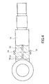
- a rod main body and a rod head are typically manufactured by processing a steel material manufactured by continuous casting. Impurities caused by center segregation exist in a central portion of the steel material manufactured by continuous casting. Therefore, as shown in FIG. 4 , when a solid rod main body 51 and a solid rod head 52 are joined by friction welding, center segregation 53 existing in respective central portions thereof is discharged to an outer periphery in the form of burrs 54 due to plastic flow occurring during the friction welding. However, the center segregation 53 is not discharged completely, and therefore the impurities remain as a thin film on a joint surface.
- Diffusible hydrogen contained in a base material gathers in the impurities remaining on the joint surface easily, causing hydrogen embrittlement on the joint surface. As a result, a delayed fracture may occur, leading to a separation fracture between the rod main body and the rod head at the joint surface.
- This invention has been designed in consideration of this problem, and an object thereof is to provide a piston rod manufacturing method with which a joint strength between a rod main body and a rod head joined by friction welding can be improved.
- This invention is a piston rod manufacturing method for manufacturing a piston rod by joining together respective end surfaces of a rod main body and a rod head.
- the piston rod manufacturing method includes a first step of hollowing out respective axial center portions of the rod main body and the rod head from the respective end surfaces thereof in order to remove impurities caused by center segregation, and a second step of joining together the respective end surfaces of the rod main body and the rod head by friction welding.
- the rod main body and the rod head are integrated by joining respective end surfaces thereof using friction welding after removing impurities existing in respective axial center portions thereof, and therefore a piston rod having no impurities on its joint surface can be manufactured.
- the joint strength between the rod main body and the rod head can be improved.
- a piston rod 1 is manufactured by joining a rod main body 2 and a rod head 3 through friction welding.
- the piston rod 1 is inserted to be free to advance and retreat into a cylinder main body of a fluid pressure cylinder used as an actuator (not shown).
- the rod main body 2 and the rod head 3 are manufactured by processing solid carbon steel manufactured by continuous casting. Steel having a carbon content of 0.45%, for example, is used as the carbon steel.
- FIG. 1 is a plan view showing the rod main body 2 and the rod head 3 prior to a process for manufacturing the piston rod 1 (i.e. prior to the friction welding).
- the rod main body 2 is constituted by a small diameter portion 2a to which a piston (not shown) that slides through a cylinder main body is coupled, and a large diameter portion 2b having a larger diameter than the small diameter portion 2a.
- the annular piston is fitted onto an outer periphery of the small diameter portion 2a and latched to a step portion 2d that forms a boundary between the small diameter portion 2a and the large diameter portion 2b, and then fixed by a nut that is fastened to a male screw portion 2e of the small diameter portion 2a.
- a planar end surface 2c is formed on the large diameter portion 2b of the rod main body 2.
- the rod head 3 is constituted by an annular clevis 3a coupled to a load, and a trunk portion 3b having an identical diameter to the large diameter portion 2b of the rod main body 2.
- a planar end surface 3c is formed on the trunk portion 3b.
- the piston rod 1 is manufactured by joining the end surface 2c of the large diameter portion 2b of the rod main body 2 and the end surface 3c of the trunk portion 3b of the rod head 3 integrally through friction welding.
- the rod main body 2 and the rod head 3 are manufactured by processing a solid steel material manufactured by continuous casting. Impurities contained in molten steel are more likely to remain in a liquid than in a solid, and therefore, during the continuous casting, impurities accumulate easily in an axial center portion that solidifies last. Hence, impurities caused by center segregation exist in the axial center portion of the steel material manufactured by continuous casting. Accordingly, impurities 10 caused by center segregation exist in an axial center portion of the rod main body 2 and an axial center portion of the trunk portion 3b of the rod head 3. In FIGs. 1 to 3 , the impurities 10 are depicted in pattern form using dotted lines.
- the impurities 10 caused by center segregation are removed by hollowing out the axial center portion of the solid rod main body 2 into a columnar shape from the end surface 2c.
- a hole portion 6 that is surrounded by an annular portion 5 and that has an opening portion in the end surface 2c is formed in the rod main body 2.
- An inner diameter of the hole portion 6 is formed such that a sectional area of the annular portion 5 of the rod main body 2 is larger than a minimum sectional area portion 2f formed on the step portion 2d.
- the inner diameter of the hole portion 6 is formed thus to ensure that the annular portion 5 does not constitute a weakest part of the piston rod 1.
- a depth of the hole portion 6 is set such that burrs 12 (see FIG. 3 ) generated during joining are formed to be short enough to be accommodated within the hole portion 6.
- a bottom portion peripheral edge 6a of the hole portion 6 is chamfered into a curved surface shape. The bottom portion peripheral edge 6a is chamfered to ensure that when a tensile compressive load acts on the piston rod 1, stress does not concentrate in the bottom portion peripheral edge 6a of the hole portion 6.
- the impurities 10 caused by center segregation are removed likewise from the rod head 3 by hollowing out the axial center portion of the solid trunk portion 3b into a columnar shape from the end surface 3c.
- a hole portion 8 that is surrounded by an annular portion 7 and that has an opening portion in the end surface 3c is formed in the trunk portion 3b of the rod head 3.
- An inner diameter and a depth of the hole portion 8 are formed at substantially identical dimensions to the hole portion 6 in the rod main body 2. Further, a bottom portion peripheral edge 8a of the hole portion 8 is chamfered into a curved surface shape, similarly to the hole portion 6 in the rod main body 2.
- the respective axial center portions of the rod main body 2 and the rod head 3 are hollowed out by cutting. It should be noted, however, that the respective axial center portions of the rod main body 2 and the rod head 3 may be hollowed out using a method other than cutting, for example deformation processing such as forging.
- the outer periphery of the rod main body 2 and the rod head 3 is processed into a smooth continuous form by removing the burrs 12 on the outer peripheral side of the piston rod 1.
- the axial center portions of the rod main body 2 and the rod head 3 are hollowed out such that the impurities 10 no longer exist on the respective end surfaces 2c, 3c thereof. As a result, no impurities exist on the joint surface 11 of the obtained piston rod 1.
- the rod main body 2 and the rod head 3 are integrated by joining the respective end surfaces 2c, 3c thereof through friction welding after removing the impurities 10 existing in the axial center portions, and therefore the piston rod 1 can be manufactured without impurities on the joint surface 11. Accordingly, intergranular fractures caused by hydrogen embrittlement on the joint surface 11 do not occur, and therefore delayed fractures can be prevented. As a result, a joint strength between the rod main body 2 and the rod head 3 can be improved.
- the hollow portion 13 exists in the interior of the piston rod 1, and therefore the high temperature portion in the vicinity of the joint surface 11 is discharged in the form of the burrs 12 to the inner peripheral side as well as the outer peripheral side during the friction welding process. Therefore, in comparison with a case where a solid rod is joined, the obtained joint surface 11 is cleaner.
- the rod main body 2 and the rod head 3 are joined by friction-welding the annular end surfaces 2c, 3c, and therefore, in comparison with a case where a solid rod is joined, the joining can be performed using a smaller amount of energy.
- a piston rod having a larger diameter than the diameter of a conventional solid piston rod can be joined using a conventional friction welding machine, enabling a reduction in equipment cost.
- the piston rod 1 can be reduced in weight.
Applications Claiming Priority (2)
| Application Number | Priority Date | Filing Date | Title |
|---|---|---|---|
| JP2009207892A JP2011056531A (ja) | 2009-09-09 | 2009-09-09 | ピストンロッドの製造方法 |
| PCT/JP2010/059986 WO2011030595A1 (fr) | 2009-09-09 | 2010-06-07 | Procédé de fabrication d'une tige de piston |
Publications (1)
| Publication Number | Publication Date |
|---|---|
| EP2476503A1 true EP2476503A1 (fr) | 2012-07-18 |
Family
ID=43732272
Family Applications (1)
| Application Number | Title | Priority Date | Filing Date |
|---|---|---|---|
| EP10815193A Withdrawn EP2476503A1 (fr) | 2009-09-09 | 2010-06-07 | Procédé de fabrication d'une tige de piston |
Country Status (6)
| Country | Link |
|---|---|
| US (1) | US20120160899A1 (fr) |
| EP (1) | EP2476503A1 (fr) |
| JP (1) | JP2011056531A (fr) |
| KR (1) | KR20120048649A (fr) |
| CN (1) | CN102481661A (fr) |
| WO (1) | WO2011030595A1 (fr) |
Cited By (1)
| Publication number | Priority date | Publication date | Assignee | Title |
|---|---|---|---|---|
| EP3040587A4 (fr) * | 2013-08-26 | 2017-03-15 | KYB-YS Co., Ltd. | Procédé de fabrication d'une tige de piston |
Families Citing this family (6)
| Publication number | Priority date | Publication date | Assignee | Title |
|---|---|---|---|---|
| CN103831581B (zh) * | 2012-11-23 | 2016-02-24 | 亚柏士气动工具股份有限公司 | 气动工具的冲击轴的制造方法及气动工具的冲击轴 |
| JP6071132B2 (ja) | 2013-03-28 | 2017-02-01 | Kyb株式会社 | 接合体 |
| CN103551477B (zh) * | 2013-11-22 | 2015-06-24 | 济宁璟华环保科技有限公司 | 活塞杆专用锻造油压机及锻造方法 |
| CN104439962A (zh) * | 2014-11-19 | 2015-03-25 | 柳州科尔特锻造机械有限公司 | 一种活塞杆加工工艺 |
| CN105328410B (zh) * | 2015-10-31 | 2017-05-10 | 长治清华机械厂 | 一种活塞杆表面小孔下封闭腔体结构多余物控制方法 |
| CN111590040B (zh) * | 2020-04-16 | 2022-04-01 | 攀钢集团攀枝花钢铁研究院有限公司 | 一种提升齿轮钢质量的小方坯连铸生产方法 |
Family Cites Families (12)
| Publication number | Priority date | Publication date | Assignee | Title |
|---|---|---|---|---|
| JPS5850189A (ja) * | 1981-09-22 | 1983-03-24 | Toyota Motor Corp | タ−ビンホイ−ルとタ−ビンシヤフトとの接合方法およびその装置 |
| BR9001916A (pt) * | 1990-04-20 | 1991-11-12 | Metal Leve Sa | Processo de obtencao de embolo refrigerado e embolo refrigerado |
| JPH05223117A (ja) * | 1991-09-11 | 1993-08-31 | Hino Motors Ltd | カウンタ軸およびその製造方法 |
| JPH0735237A (ja) * | 1993-07-21 | 1995-02-07 | Koyo Seiko Co Ltd | ピストンとその製造方法 |
| JP3827188B2 (ja) * | 1999-02-24 | 2006-09-27 | カヤバ工業株式会社 | 流体圧シリンダにおける流路成形方法 |
| DE10158111A1 (de) * | 2000-11-27 | 2002-07-04 | Sauer Danfoss Inc | Geschlossener Hohlkolben und Verfahren zu seiner Herstellung |
| JP2002224706A (ja) * | 2001-02-07 | 2002-08-13 | Kawasaki Steel Corp | 棒材圧延設備列 |
| JP4063703B2 (ja) * | 2003-04-04 | 2008-03-19 | 株式会社丸山製作所 | クランク軸の製造方法 |
| JP2006263782A (ja) * | 2005-03-24 | 2006-10-05 | Kuroki Kogyosho:Kk | 異材の接合法 |
| FR2883940B1 (fr) * | 2005-03-31 | 2008-10-10 | Airbus France Sas | Bielle structurale creuse et procede de fabrication d'une telle bielle |
| JP5060086B2 (ja) * | 2006-09-01 | 2012-10-31 | 日本軽金属株式会社 | サスペンション部品およびサスペンション部品の製造方法 |
| US20090222028A1 (en) | 2008-02-29 | 2009-09-03 | Ethicon Endo-Surgery, Inc. | Methods and devices for fixing antenna orientation in a restriction system |
-
2009
- 2009-09-09 JP JP2009207892A patent/JP2011056531A/ja active Pending
-
2010
- 2010-06-07 EP EP10815193A patent/EP2476503A1/fr not_active Withdrawn
- 2010-06-07 US US13/394,193 patent/US20120160899A1/en not_active Abandoned
- 2010-06-07 CN CN2010800403197A patent/CN102481661A/zh active Pending
- 2010-06-07 KR KR1020127004864A patent/KR20120048649A/ko not_active Application Discontinuation
- 2010-06-07 WO PCT/JP2010/059986 patent/WO2011030595A1/fr active Application Filing
Non-Patent Citations (1)
| Title |
|---|
| See references of WO2011030595A1 * |
Cited By (1)
| Publication number | Priority date | Publication date | Assignee | Title |
|---|---|---|---|---|
| EP3040587A4 (fr) * | 2013-08-26 | 2017-03-15 | KYB-YS Co., Ltd. | Procédé de fabrication d'une tige de piston |
Also Published As
| Publication number | Publication date |
|---|---|
| JP2011056531A (ja) | 2011-03-24 |
| US20120160899A1 (en) | 2012-06-28 |
| KR20120048649A (ko) | 2012-05-15 |
| CN102481661A (zh) | 2012-05-30 |
| WO2011030595A1 (fr) | 2011-03-17 |
Similar Documents
| Publication | Publication Date | Title |
|---|---|---|
| EP2476503A1 (fr) | Procédé de fabrication d'une tige de piston | |
| JP5415455B2 (ja) | 摩擦プラグ溶接方法及びシステム | |
| WO2016163214A1 (fr) | Procédé de soudage par friction-malaxage et structure soudée | |
| EP3040587B1 (fr) | Procédé de fabrication d'une tige de piston | |
| KR101559263B1 (ko) | 헤드 교환식 절삭 공구용 홀더 및 헤드 교환식 절삭 공구 | |
| JP6071132B2 (ja) | 接合体 | |
| JP2013517436A (ja) | 流体循環チューブを結合させるためのデバイスおよび関連方法 | |
| US7934908B2 (en) | Impeller manufacturing method and impeller | |
| JP2004209499A (ja) | ガスボンベ用ライナおよびその製造方法 | |
| JP5412406B2 (ja) | 中子支持金具及びその製造方法 | |
| CN101769287A (zh) | 安全销钉及其制造方法 | |
| JP2010228531A (ja) | すり割り付き孔の加工方法 | |
| JP4628349B2 (ja) | 鋳造方法及び鋳造装置 | |
| JP2008161918A (ja) | 摩擦圧接におけるバリ処理方法 | |
| KR101353353B1 (ko) | 캠샤프트 어셈블리 및 캠샤프트 어셈블리 제조방법 | |
| US11678428B2 (en) | Method of assembling an electrode | |
| JP2014065052A (ja) | 異材鍛造方法及びドグクラッチ用鍛造品 | |
| JP2001079657A (ja) | ロウ付による固定方法 | |
| TWM464257U (zh) | 放電加工機治夾具的組合式拉栓器 | |
| JP2008284597A (ja) | 圧延ロール及び圧延機 | |
| JPH01306038A (ja) | 管状部を有する金属製品の製造方法 |
Legal Events
| Date | Code | Title | Description |
|---|---|---|---|
| PUAI | Public reference made under article 153(3) epc to a published international application that has entered the european phase |
Free format text: ORIGINAL CODE: 0009012 |
|
| 17P | Request for examination filed |
Effective date: 20120322 |
|
| AK | Designated contracting states |
Kind code of ref document: A1 Designated state(s): AL AT BE BG CH CY CZ DE DK EE ES FI FR GB GR HR HU IE IS IT LI LT LU LV MC MK MT NL NO PL PT RO SE SI SK SM TR |
|
| DAX | Request for extension of the european patent (deleted) | ||
| STAA | Information on the status of an ep patent application or granted ep patent |
Free format text: STATUS: THE APPLICATION HAS BEEN WITHDRAWN |
|
| 18W | Application withdrawn |
Effective date: 20140415 |