EP2476176B1 - Verfahren zur regelung von stromrichtern und anordnung zur durchführung des verfahrens - Google Patents
Verfahren zur regelung von stromrichtern und anordnung zur durchführung des verfahrens Download PDFInfo
- Publication number
- EP2476176B1 EP2476176B1 EP20100743140 EP10743140A EP2476176B1 EP 2476176 B1 EP2476176 B1 EP 2476176B1 EP 20100743140 EP20100743140 EP 20100743140 EP 10743140 A EP10743140 A EP 10743140A EP 2476176 B1 EP2476176 B1 EP 2476176B1
- Authority
- EP
- European Patent Office
- Prior art keywords
- sequence system
- components
- transformation
- output
- current
- Prior art date
- Legal status (The legal status is an assumption and is not a legal conclusion. Google has not performed a legal analysis and makes no representation as to the accuracy of the status listed.)
- Active
Links
Images
Classifications
-
- H—ELECTRICITY
- H02—GENERATION; CONVERSION OR DISTRIBUTION OF ELECTRIC POWER
- H02J—ELECTRIC POWER NETWORKS; CIRCUIT ARRANGEMENTS OR SYSTEMS FOR SUPPLYING OR DISTRIBUTING ELECTRIC POWER; SYSTEMS FOR STORING ELECTRIC ENERGY
- H02J3/00—Circuit arrangements for AC mains or AC distribution networks
- H02J3/18—Arrangements for adjusting, eliminating or compensating reactive power in networks
- H02J3/1821—Arrangements for adjusting, eliminating or compensating reactive power in networks using shunt compensators
- H02J3/1835—Arrangements for adjusting, eliminating or compensating reactive power in networks using shunt compensators with stepless control
- H02J3/1842—Arrangements for adjusting, eliminating or compensating reactive power in networks using shunt compensators with stepless control having reactive elements actively controlled by bridge converters, e.g. active filters or static compensators [STATCOM]
-
- Y—GENERAL TAGGING OF NEW TECHNOLOGICAL DEVELOPMENTS; GENERAL TAGGING OF CROSS-SECTIONAL TECHNOLOGIES SPANNING OVER SEVERAL SECTIONS OF THE IPC; TECHNICAL SUBJECTS COVERED BY FORMER USPC CROSS-REFERENCE ART COLLECTIONS [XRACs] AND DIGESTS
- Y02—TECHNOLOGIES OR APPLICATIONS FOR MITIGATION OR ADAPTATION AGAINST CLIMATE CHANGE
- Y02E—REDUCTION OF GREENHOUSE GAS [GHG] EMISSIONS, RELATED TO ENERGY GENERATION, TRANSMISSION OR DISTRIBUTION
- Y02E40/00—Technologies for an efficient electrical power generation, transmission or distribution
- Y02E40/20—Active power filtering [APF]
Definitions
- the invention relates to a method for controlling converters for Ausreglung the counter-voltage in a multi-phase electrical energy transmission network in which detected via a connected to the power transmission network polyphase connection line phase currents on the connecting line and transformed by transformation into Mitsystem current components, voltages to the phases the connecting line detected and formed by means of transformation negative sequence voltage components.
- the invention further relates to an arrangement for carrying out the method according to one of the preceding claims with a current detection device for the phase currents on the connecting line and a downstream transformation device for transforming the phase currents in Mitsystem current components, a voltage detection device for the voltages at the phases of the connecting line and a downstream further transformation device with a transformation block for transforming the voltages in negative sequence voltage components.
- the object of the invention is to design such a method so that it is easy to parameterize at each operating point.
- a method for controlling converters for controlling the counter voltage in a multi-phase electrical energy transmission network in which detected via a connected to the power transmission network polyphase connection line phase currents on the connecting line and transformed by transformation into Mitsystem current components;
- voltages are detected at the phases of the connecting line and formed therefrom by means of transformation negative sequence voltage components, the negative sequence voltage components supplied to a voltage regulator, are formed in the negative sequence counter-current components serving to reduce the negative sequence, and the negative sequence current Components are fed to a setpoint input and the Mitsystem current components to an actual value input of a current regulator whose output variables are used after reverse transformation as switching currents for switching units of the power converters.
- a significant advantage of the method according to the invention is that in him the negative sequence voltage is compensated by controlling the negative sequence current. This ensures that the negative-sequence current and the negative sequence voltage deliver a pure negative-sequence reactive power to support the voltage in the network, with neither the negative sequence current nor the negative sequence voltage containing a zero component.
- the negative-sequence current components generated by the voltage regulator are regulated by means of the current regulator in an inner control loop. It is thus formed a cascade control with the voltage regulator and the current controller, which is easy to parameterize at each operating point and manages without dynamic limits and compensations.
- the regulation of the counter-system voltage is decoupled from current, voltage, reactive power and active power setpoints.
- a reactive power voltage regulation can advantageously be included in the method according to the invention by forming from the voltages on the phases of the connection line by means of transformation system components voltage, the Mitsystem voltage components are fed to a reactive power voltage regulator whose output current is supplied to an input of a summer, and the negative sequence current components are supplied at the output of the voltage regulator to another input of the summer, the output of which is connected to the setpoint input of the current controller. This limits the negative sequence reactive power.
- the method according to the invention is supplemented to the extent that the positive-sequence voltage components are connected to an active power voltage regulator are fed, the output current is fed to an additional input of the summer.
- mitsystem voltage components are formed from the voltages on the phases of the connecting line by means of transformation, the Mitsystem voltage components are fed to an active power voltage regulator whose output current a additional input of a summer is supplied, and the negative sequence current components are supplied at the output of the voltage regulator to another input of the summer whose output is connected to the setpoint input of the current controller.
- the active power voltage regulator whose output current a additional input of a summer is supplied
- the negative sequence current components are supplied at the output of the voltage regulator to another input of the summer whose output is connected to the setpoint input of the current controller.
- the negative sequence voltage components and the positive sequence voltage components can be formed in different ways; however, it is considered advantageous if these components are formed by means of Clark transformation with subsequent filtering and Park transformation.
- a voltage regulator differently constructed regulators can be used in the method according to the invention; however, it is considered advantageous, if a voltage regulator is used, each with a PI controller for the negative sequence voltage components, the output currents of the two PI controller one vector rotation to achieve a -90 ° phase position to the negative sequence voltage components subject to be limited and freely selectable.
- the invention is further based on the object of specifying an arrangement for carrying out the above-described method according to the invention, which can be configured comparatively easily.
- an arrangement comprises a current detection device for the phase currents on the connection line with a downstream transformation device for transforming the phase currents in Mitsystem current components and a voltage detection device for the voltages at the phases of the connecting line with a downstream further transformation device with a transformation block for transforming the voltages in negative sequence voltage components;
- the transformation module is followed by a voltage regulator, in which negative sequence current components serving to reduce the negative sequence system are formed, and the voltage regulator is a current regulator with a nominal value input receiving the negative sequence current component and an actual value detecting the positive sequence current components Downstream input, wherein the current regulator is connected on the output side via a back-transformation device with switching inputs of switching units of the power converter.
- the further transformation device advantageously has a further transformation module, which forms from the voltages at the phases of the connecting line by means of transformation Mitsystem voltage components at its output;
- the further transformation module is a reactive power voltage regulator downstream, whose output is connected to an input of a downstream summer, and the output of the voltage regulator is connected to a further input of the summer whose output is connected to the setpoint input of the current controller.
- an active power voltage regulator is advantageously connected to the further transformation module whose output is connected to an additional input of the summer.
- the arrangement according to the invention also works reliably if, with the dispensing with a reactive power voltage control, an embodiment is selected in which the further transformation device has a further transformation module that forms the voltages of the phases of the connecting line by means of transforming system voltage components at its output, the further transformation block is followed by an active power voltage regulator whose output is connected to an additional input of a summer, and the output of the voltage regulator is connected to a further input of the summer whose output is connected to the setpoint input of the current controller.
- the transformation components of the further transformation device can be designed in different ways;
- the one transformation module contains a filter for forming the negative sequence voltage components and a downstream this park transformer and the further transformation block another filter for forming the Mitsystem voltage components and a subordinate this further Park transformer.
- the further transformation device advantageously has a Clark transformer on the input side.
- the voltage regulator of the arrangement according to the invention an embodiment is considered advantageous in which the voltage regulator in each case has a PI controller for the negative sequence voltage components and the two PI controllers an arrangement for vector rotation to achieve a -90 ° -phase position to the Negative system voltage components and a limiter arrangement are connected downstream.
- the advantage of this embodiment of the voltage regulator is that it can be made relatively simple and therefore inexpensive.
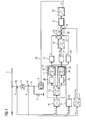
- FIG. 1 shows, is connected to a multi-phase high-voltage AC line 1 as electrical energy transmission network via a multi-phase connecting line 2, a reactive power compensator 3, which is connected in parallel to a filter 4 in parallel.
- connection line 2 is located in the illustrated embodiment, a star-delta transformer. 5
- connection line 2 is also a current detection device 6, which consists of current transformers in the usual way and therefore for the sake of clarity is not shown in detail here.
- Secondary currents is1, is2 and is3 are output by the current detection device 6 for each phase of the connection line 2 and fed to a transformation device 7, which transforms the detected currents is1, is2 and is3 into co-system current components imp1 and imq1 in a manner known per se.
- the co-system current components imp1 and imq1 are supplied as actual values to an actual value input 8 of a current regulator 9, which will be described in more detail later.
- Voltages u1, u2 and u3 on the high-voltage AC voltage line 1 are detected by means of a voltage detection device 10, which is likewise not shown in detail for the sake of better clarity, and supplied to a star-delta converter 11, which is designed in a known manner and therefore not described in detail here needs to be.
- the star-delta converter 11 is followed by a further transformation means 12, the input side includes a Clark transformer 13, by means of which a known Clark transformation is performed, so that at the output of the Clark transformer voltage components ⁇ and ⁇ are pending ,
- a transformation module 14 is connected to the Clark transformer 13, which contains a negative-sequence filter 15 and a park transformer 16 arranged downstream of it.
- a known per se Park transformation is made, so that at the output of the transformation block 14 negative sequence voltage components p2 and q2 occur.
- a voltage regulator 17 is connected, with which a negative sequence voltage control is made.
- a control takes place with a setpoint value "zero", so that negative sequence current components ip2 and iq2, which are converted in a downstream transformer 18 into negative sequence current components ip1 and iq1, are produced at the output of the voltage regulator.
- the further transformation device 12 further includes a further transformation module 19, which is also connected to the Clark transformer 13 and the input side has a Mitsystem filter 20. This is followed by another park transformer 21, which performs a park transformation, so that arise at its output Mitsystem voltage components p1 and q1.
- the component q1 is supplied to a downstream reactive power voltage regulator 22, which operates with a predetermined voltage setpoint and generates at its output a Mitsystem current component iq1.
- the further Clark transformer 21 is also connected to an active power regulator 23 and is supplied with the real Mitsystem voltage component p1.
- This controller also has a set power setpoint and generates a co-system current component ip1 at its output.
- the outputs of the voltage regulator 17 and the downstream transformer 18 are fed to an input 24 of a summer 25, which is connected to a further input 26 at the output of the reactive power controller 22.
- An additional input 27 of the summer 25 is connected to the output of the active power controller 23.
- the output of the adder 25 is connected to a setpoint input 28 of the current regulator 9, which generates at its output corresponding Mitsystem current components. These are fed to a module 29 for inverse transformation, in which switching currents i1, i2 and i3 are formed for switching units (not shown) of the converters of the reactive power compensator 3, which are supplied to the reactive power compensator 3 via a line 30.
- a PLL (Phase-Locked Loop) circuit 31 is connected, which serves in a manner not shown for synchronizing the individual components of the arrangement shown.
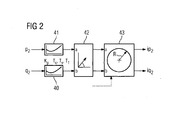
- FIG. 2 is an embodiment of the voltage regulator 17 according to FIG. 1 shown.
- the voltage regulator contains on the input side each a PI controller 40 and 41, which are acted upon at their inputs to the negative sequence voltage components p2 and q2, ie with the output variables of the parking transformer 16 according to FIG. 1 ,
- the outputs of the two PI controllers 40 and 41 are applied to an array 42 in which rotation is made such that the phasing of the vector is 90 ° to the negative sequence voltage components.
- the arrangement for vector rotation 42 is followed by a limiter arrangement 43 in which a vectorial limitation according to the properties of the network with the high-voltage AC voltage line 1 is set.
Landscapes
- Engineering & Computer Science (AREA)
- Power Engineering (AREA)
- Supply And Distribution Of Alternating Current (AREA)
- Control Of Electrical Variables (AREA)
- Inverter Devices (AREA)
- Ac-Ac Conversion (AREA)
Priority Applications (1)
| Application Number | Priority Date | Filing Date | Title |
|---|---|---|---|
| PL10743140T PL2476176T3 (pl) | 2009-09-08 | 2010-08-17 | Sposób regulacji prostowników prądu i układ do realizacji tego sposobu |
Applications Claiming Priority (2)
| Application Number | Priority Date | Filing Date | Title |
|---|---|---|---|
| DE102009040745A DE102009040745A1 (de) | 2009-09-08 | 2009-09-08 | Verfahren zur Regelung von Stromrichtern und Anordnung zur Durchführung des Verfahrens |
| PCT/EP2010/061955 WO2011029700A2 (de) | 2009-09-08 | 2010-08-17 | Verfahren zur regelung von stromrichtern und anordnung zur durchführung des verfahrens |
Publications (2)
| Publication Number | Publication Date |
|---|---|
| EP2476176A2 EP2476176A2 (de) | 2012-07-18 |
| EP2476176B1 true EP2476176B1 (de) | 2015-05-20 |
Family
ID=43571101
Family Applications (1)
| Application Number | Title | Priority Date | Filing Date |
|---|---|---|---|
| EP20100743140 Active EP2476176B1 (de) | 2009-09-08 | 2010-08-17 | Verfahren zur regelung von stromrichtern und anordnung zur durchführung des verfahrens |
Country Status (9)
| Country | Link |
|---|---|
| US (1) | US8907640B2 (da) |
| EP (1) | EP2476176B1 (da) |
| CN (1) | CN102714413B (da) |
| DE (1) | DE102009040745A1 (da) |
| DK (1) | DK2476176T3 (da) |
| ES (1) | ES2538202T3 (da) |
| PL (1) | PL2476176T3 (da) |
| RU (1) | RU2543088C2 (da) |
| WO (1) | WO2011029700A2 (da) |
Families Citing this family (8)
| Publication number | Priority date | Publication date | Assignee | Title |
|---|---|---|---|---|
| CN103181052B (zh) | 2010-09-06 | 2016-01-13 | Sma太阳能技术股份公司 | 用于稳定供电网的方法 |
| WO2012062323A2 (en) | 2010-11-10 | 2012-05-18 | Vestas Wind Systems A/S | Method and system for operating a wind turbine |
| US11454999B2 (en) * | 2012-08-29 | 2022-09-27 | Stem, Inc. | Method and apparatus for automatically reconfiguring multi-phased networked energy storage devices at a site |
| CN103066866B (zh) | 2012-12-20 | 2014-12-10 | 天津大学 | 基于模型预测控制的主动前端整流器滤波延迟补偿方法 |
| EP2768104A1 (fr) * | 2013-02-15 | 2014-08-20 | Alstom Technology Ltd | Commande d'un convertisseur de tension triphasé en mode déséquilibré |
| DE102013114729B4 (de) * | 2013-12-20 | 2021-09-30 | Sma Solar Technology Ag | Wechselrichter und Verfahren zum Detektieren eines Phasenausfalls in einem Energieversorgungsnetz |
| DK3340453T3 (da) * | 2016-12-22 | 2021-04-06 | General Electric Technology Gmbh | Fremgangsmåde til at konfigurere et styresystem med lukket kredsløb |
| EP3840159B1 (en) * | 2019-12-20 | 2023-08-23 | Hitachi Energy Switzerland AG | Transformer arrangement |
Family Cites Families (10)
| Publication number | Priority date | Publication date | Assignee | Title |
|---|---|---|---|---|
| RU2059256C1 (ru) * | 1992-08-20 | 1996-04-27 | Александр Сергеевич Бочев | Устройство для измерения коэффициента обратной последовательности напряжения |
| DE19737590C1 (de) | 1997-08-28 | 1998-10-22 | Siemens Ag | Verfahren und Vorrichtung zur Verbesserung der Spannungsqualität eines unterlagerten Netzteiles |
| US6052297A (en) * | 1998-05-06 | 2000-04-18 | Mitsubishi Denki Kabushiki Kaisha | Power conversion apparatus |
| EP1553693B1 (en) | 2002-10-17 | 2007-12-19 | Denso Corporation | Ac rotary electric machine magnetic noise reduction method, motor control device and ac rotary electric machine using the same |
| CN1411118A (zh) * | 2002-12-06 | 2003-04-16 | 清华大学 | 有源电力滤波器的变流器直流侧电压闭环控制方法和系统 |
| CN1992496B (zh) * | 2006-03-08 | 2010-05-12 | 合肥阳光电源有限公司 | 风力发电用双馈型交直交变流器的控制结构 |
| DE102006054870A1 (de) * | 2006-11-20 | 2008-06-12 | Repower Systems Ag | Windenergieanlage mit Gegensystemregelung und Betriebsverfahren |
| JP5259077B2 (ja) * | 2006-12-04 | 2013-08-07 | 株式会社京三製作所 | 瞬時電圧低下補償回路、電力変換装置、瞬時電圧低下補償方法及び瞬時電圧低下補償プログラム |
| CN100588073C (zh) * | 2008-06-05 | 2010-02-03 | 上海交通大学 | 柔性直流输电变流器的电流控制方法及装置 |
| JP5004366B2 (ja) * | 2009-12-07 | 2012-08-22 | 株式会社京三製作所 | 不平衡電圧補償方法、不平衡電圧補償装置、三相コンバータの制御方法、および、三相コンバータの制御装置 |
-
2009
- 2009-09-08 DE DE102009040745A patent/DE102009040745A1/de not_active Ceased
-
2010
- 2010-08-17 DK DK10743140.5T patent/DK2476176T3/da active
- 2010-08-17 US US13/394,869 patent/US8907640B2/en active Active
- 2010-08-17 WO PCT/EP2010/061955 patent/WO2011029700A2/de not_active Ceased
- 2010-08-17 ES ES10743140.5T patent/ES2538202T3/es active Active
- 2010-08-17 CN CN201080049028.4A patent/CN102714413B/zh active Active
- 2010-08-17 RU RU2012113557/07A patent/RU2543088C2/ru active
- 2010-08-17 PL PL10743140T patent/PL2476176T3/pl unknown
- 2010-08-17 EP EP20100743140 patent/EP2476176B1/de active Active
Also Published As
| Publication number | Publication date |
|---|---|
| WO2011029700A3 (de) | 2011-11-03 |
| CN102714413B (zh) | 2014-12-03 |
| WO2011029700A2 (de) | 2011-03-17 |
| DE102009040745A1 (de) | 2011-03-17 |
| RU2543088C2 (ru) | 2015-02-27 |
| US8907640B2 (en) | 2014-12-09 |
| CN102714413A (zh) | 2012-10-03 |
| US20120187924A1 (en) | 2012-07-26 |
| ES2538202T3 (es) | 2015-06-18 |
| DK2476176T3 (da) | 2015-08-03 |
| EP2476176A2 (de) | 2012-07-18 |
| RU2012113557A (ru) | 2013-10-20 |
| PL2476176T3 (pl) | 2015-11-30 |
Similar Documents
| Publication | Publication Date | Title |
|---|---|---|
| EP2476176B1 (de) | Verfahren zur regelung von stromrichtern und anordnung zur durchführung des verfahrens | |
| EP3602721B1 (de) | Verfahren zum einspeisen elektrischer leistung in ein elektrisches versorgungsnetz | |
| DE102012201045B4 (de) | Verfahren zum Steuern des Leistungsfaktors eines Drei-Phasenwandlers, Verfahren zum Steuern der Reaktivleistung von Drei-Phasenwandlern und Steuervorrichtung für Drei-Phasenwandler | |
| EP2872777B1 (de) | Verfahren zum steuern eines elektrischen erzeugers | |
| EP2179498B1 (de) | Verfahren und vorrichtung zur kompensation von schwingungseffekten bei netzunsymmetrie bei einer doppeltgespeisten asynchronmaschine | |
| DE102010053638B4 (de) | Kompensationsverfahren für asymmetrische Spannung, asymmetrischer Spannungskompensator, Drei-Phasenwandler-Steuerverfahren und Steuervorrichtung für Drei-Phasen-Wandler | |
| EP2769448B1 (de) | Verfahren zum einspeisen elektrischen stroms in ein elektrisches netz | |
| EP2102495B1 (de) | Windenergieanlage mit gegensystemregelung und betriebsverfahren | |
| EP2955808B1 (de) | Verfahren zur Regelung einer Windenergieanlage während eines asymmetrischen Netzfehlers | |
| EP3326255B1 (de) | Verfahren und vorrichtung zum erfassen einer elektrischen spannung in einem versorgungsnetz | |
| EP3595121A1 (de) | Verfahren und vorrichtung zum einspeisen elektrischer energie in ein elektrisches versorgungsnetz | |
| EP3676953B1 (de) | Verfahren zum steuern eines mehrphasigen fremderregten synchrongenerators einer windenergieanlage und windenergieanlage | |
| DE102021101836A1 (de) | Netzgekoppelter wechselrichter und verfahren zur verringerung von schwankungen der netzfrequenz | |
| DE102011053237A1 (de) | Verfahren zur Stabilisierung eines elektrischen Versorgungsnetzes | |
| WO2016151014A1 (de) | Verfahren zum steuern eines synchrongenerators einer getriebelosen windenergieanlage | |
| EP2766980B1 (de) | Konverter in dreieckskonfiguration | |
| DE102012220582A1 (de) | Windenergieanlage und Verfahren zum Einspeisen elektrischer Energie | |
| EP0790689B1 (de) | Verfahren zur Verbesserung der Spannungsqualität in einem Drehstromnetz und Anlage für die Durchführung des Verfahrens | |
| DE102016203123A1 (de) | Vorrichtung und Verfahren zur Regelung eines Wechselrichters | |
| WO2011088885A1 (de) | Verfahren zum betreiben eines dreiphasigen umrichters in dreieckschaltung und symmetriereinrichtung für einen solchen umrichter | |
| EP3616290A1 (de) | Verfahren zum erfassen einer inselnetzbildung | |
| EP2911259B1 (de) | Nutzung eines drehzahlgeregelten Antriebs zur Netzstabilisierung | |
| WO1996018230A1 (de) | Verfahren und vorrichtung zur erzeugung eines beliebigen m-phasigen stromsystems n-ter ordnung einer umrichtergespeisten einrichtung | |
| EP4147336A1 (de) | Netzumrichter und regelungsverfahren für den betrieb an verzerrten einphasennetzen | |
| DE102012222948A1 (de) | Verfahren und Schaltungsanordnung zum Stabilisieren eines Wechselstromnetzes |
Legal Events
| Date | Code | Title | Description |
|---|---|---|---|
| PUAI | Public reference made under article 153(3) epc to a published international application that has entered the european phase |
Free format text: ORIGINAL CODE: 0009012 |
|
| 17P | Request for examination filed |
Effective date: 20120229 |
|
| AK | Designated contracting states |
Kind code of ref document: A2 Designated state(s): AL AT BE BG CH CY CZ DE DK EE ES FI FR GB GR HR HU IE IS IT LI LT LU LV MC MK MT NL NO PL PT RO SE SI SK SM TR |
|
| DAX | Request for extension of the european patent (deleted) | ||
| RAP1 | Party data changed (applicant data changed or rights of an application transferred) |
Owner name: SIEMENS AKTIENGESELLSCHAFT |
|
| GRAP | Despatch of communication of intention to grant a patent |
Free format text: ORIGINAL CODE: EPIDOSNIGR1 |
|
| INTG | Intention to grant announced |
Effective date: 20141208 |
|
| GRAS | Grant fee paid |
Free format text: ORIGINAL CODE: EPIDOSNIGR3 |
|
| GRAA | (expected) grant |
Free format text: ORIGINAL CODE: 0009210 |
|
| AK | Designated contracting states |
Kind code of ref document: B1 Designated state(s): AL AT BE BG CH CY CZ DE DK EE ES FI FR GB GR HR HU IE IS IT LI LT LU LV MC MK MT NL NO PL PT RO SE SI SK SM TR |
|
| REG | Reference to a national code |
Ref country code: GB Ref legal event code: FG4D Free format text: NOT ENGLISH |
|
| REG | Reference to a national code |
Ref country code: CH Ref legal event code: NV Representative=s name: SIEMENS SCHWEIZ AG, CH Ref country code: CH Ref legal event code: EP |
|
| REG | Reference to a national code |
Ref country code: AT Ref legal event code: REF Ref document number: 728176 Country of ref document: AT Kind code of ref document: T Effective date: 20150615 |
|
| REG | Reference to a national code |
Ref country code: IE Ref legal event code: FG4D Free format text: LANGUAGE OF EP DOCUMENT: GERMAN |
|
| REG | Reference to a national code |
Ref country code: ES Ref legal event code: FG2A Ref document number: 2538202 Country of ref document: ES Kind code of ref document: T3 Effective date: 20150618 |
|
| REG | Reference to a national code |
Ref country code: DE Ref legal event code: R096 Ref document number: 502010009558 Country of ref document: DE |
|
| REG | Reference to a national code |
Ref country code: DK Ref legal event code: T3 Effective date: 20150730 |
|
| REG | Reference to a national code |
Ref country code: SE Ref legal event code: TRGR |
|
| REG | Reference to a national code |
Ref country code: NL Ref legal event code: T3 |
|
| REG | Reference to a national code |
Ref country code: LT Ref legal event code: MG4D |
|
| PG25 | Lapsed in a contracting state [announced via postgrant information from national office to epo] |
Ref country code: LT Free format text: LAPSE BECAUSE OF FAILURE TO SUBMIT A TRANSLATION OF THE DESCRIPTION OR TO PAY THE FEE WITHIN THE PRESCRIBED TIME-LIMIT Effective date: 20150520 Ref country code: FI Free format text: LAPSE BECAUSE OF FAILURE TO SUBMIT A TRANSLATION OF THE DESCRIPTION OR TO PAY THE FEE WITHIN THE PRESCRIBED TIME-LIMIT Effective date: 20150520 Ref country code: HR Free format text: LAPSE BECAUSE OF FAILURE TO SUBMIT A TRANSLATION OF THE DESCRIPTION OR TO PAY THE FEE WITHIN THE PRESCRIBED TIME-LIMIT Effective date: 20150520 Ref country code: NO Free format text: LAPSE BECAUSE OF FAILURE TO SUBMIT A TRANSLATION OF THE DESCRIPTION OR TO PAY THE FEE WITHIN THE PRESCRIBED TIME-LIMIT Effective date: 20150820 Ref country code: PT Free format text: LAPSE BECAUSE OF FAILURE TO SUBMIT A TRANSLATION OF THE DESCRIPTION OR TO PAY THE FEE WITHIN THE PRESCRIBED TIME-LIMIT Effective date: 20150921 |
|
| PG25 | Lapsed in a contracting state [announced via postgrant information from national office to epo] |
Ref country code: IS Free format text: LAPSE BECAUSE OF FAILURE TO SUBMIT A TRANSLATION OF THE DESCRIPTION OR TO PAY THE FEE WITHIN THE PRESCRIBED TIME-LIMIT Effective date: 20150920 Ref country code: GR Free format text: LAPSE BECAUSE OF FAILURE TO SUBMIT A TRANSLATION OF THE DESCRIPTION OR TO PAY THE FEE WITHIN THE PRESCRIBED TIME-LIMIT Effective date: 20150821 Ref country code: BG Free format text: LAPSE BECAUSE OF FAILURE TO SUBMIT A TRANSLATION OF THE DESCRIPTION OR TO PAY THE FEE WITHIN THE PRESCRIBED TIME-LIMIT Effective date: 20150820 Ref country code: LV Free format text: LAPSE BECAUSE OF FAILURE TO SUBMIT A TRANSLATION OF THE DESCRIPTION OR TO PAY THE FEE WITHIN THE PRESCRIBED TIME-LIMIT Effective date: 20150520 |
|
| REG | Reference to a national code |
Ref country code: PL Ref legal event code: T3 |
|
| PG25 | Lapsed in a contracting state [announced via postgrant information from national office to epo] |
Ref country code: EE Free format text: LAPSE BECAUSE OF FAILURE TO SUBMIT A TRANSLATION OF THE DESCRIPTION OR TO PAY THE FEE WITHIN THE PRESCRIBED TIME-LIMIT Effective date: 20150520 |
|
| REG | Reference to a national code |
Ref country code: DE Ref legal event code: R097 Ref document number: 502010009558 Country of ref document: DE |
|
| PG25 | Lapsed in a contracting state [announced via postgrant information from national office to epo] |
Ref country code: CZ Free format text: LAPSE BECAUSE OF FAILURE TO SUBMIT A TRANSLATION OF THE DESCRIPTION OR TO PAY THE FEE WITHIN THE PRESCRIBED TIME-LIMIT Effective date: 20150520 Ref country code: RO Free format text: LAPSE BECAUSE OF NON-PAYMENT OF DUE FEES Effective date: 20150520 Ref country code: SK Free format text: LAPSE BECAUSE OF FAILURE TO SUBMIT A TRANSLATION OF THE DESCRIPTION OR TO PAY THE FEE WITHIN THE PRESCRIBED TIME-LIMIT Effective date: 20150520 |
|
| PLBE | No opposition filed within time limit |
Free format text: ORIGINAL CODE: 0009261 |
|
| STAA | Information on the status of an ep patent application or granted ep patent |
Free format text: STATUS: NO OPPOSITION FILED WITHIN TIME LIMIT |
|
| PG25 | Lapsed in a contracting state [announced via postgrant information from national office to epo] |
Ref country code: MC Free format text: LAPSE BECAUSE OF FAILURE TO SUBMIT A TRANSLATION OF THE DESCRIPTION OR TO PAY THE FEE WITHIN THE PRESCRIBED TIME-LIMIT Effective date: 20150520 Ref country code: LU Free format text: LAPSE BECAUSE OF FAILURE TO SUBMIT A TRANSLATION OF THE DESCRIPTION OR TO PAY THE FEE WITHIN THE PRESCRIBED TIME-LIMIT Effective date: 20150817 |
|
| 26N | No opposition filed |
Effective date: 20160223 |
|
| PG25 | Lapsed in a contracting state [announced via postgrant information from national office to epo] |
Ref country code: SI Free format text: LAPSE BECAUSE OF FAILURE TO SUBMIT A TRANSLATION OF THE DESCRIPTION OR TO PAY THE FEE WITHIN THE PRESCRIBED TIME-LIMIT Effective date: 20150520 |
|
| REG | Reference to a national code |
Ref country code: IE Ref legal event code: MM4A |
|
| PG25 | Lapsed in a contracting state [announced via postgrant information from national office to epo] |
Ref country code: IE Free format text: LAPSE BECAUSE OF NON-PAYMENT OF DUE FEES Effective date: 20150817 |
|
| REG | Reference to a national code |
Ref country code: FR Ref legal event code: PLFP Year of fee payment: 7 |
|
| REG | Reference to a national code |
Ref country code: AT Ref legal event code: MM01 Ref document number: 728176 Country of ref document: AT Kind code of ref document: T Effective date: 20150817 |
|
| PG25 | Lapsed in a contracting state [announced via postgrant information from national office to epo] |
Ref country code: AT Free format text: LAPSE BECAUSE OF NON-PAYMENT OF DUE FEES Effective date: 20150817 |
|
| PG25 | Lapsed in a contracting state [announced via postgrant information from national office to epo] |
Ref country code: MT Free format text: LAPSE BECAUSE OF FAILURE TO SUBMIT A TRANSLATION OF THE DESCRIPTION OR TO PAY THE FEE WITHIN THE PRESCRIBED TIME-LIMIT Effective date: 20150520 |
|
| PG25 | Lapsed in a contracting state [announced via postgrant information from national office to epo] |
Ref country code: SM Free format text: LAPSE BECAUSE OF FAILURE TO SUBMIT A TRANSLATION OF THE DESCRIPTION OR TO PAY THE FEE WITHIN THE PRESCRIBED TIME-LIMIT Effective date: 20150520 Ref country code: HU Free format text: LAPSE BECAUSE OF FAILURE TO SUBMIT A TRANSLATION OF THE DESCRIPTION OR TO PAY THE FEE WITHIN THE PRESCRIBED TIME-LIMIT; INVALID AB INITIO Effective date: 20100817 |
|
| PG25 | Lapsed in a contracting state [announced via postgrant information from national office to epo] |
Ref country code: CY Free format text: LAPSE BECAUSE OF FAILURE TO SUBMIT A TRANSLATION OF THE DESCRIPTION OR TO PAY THE FEE WITHIN THE PRESCRIBED TIME-LIMIT Effective date: 20150520 |
|
| PG25 | Lapsed in a contracting state [announced via postgrant information from national office to epo] |
Ref country code: BE Free format text: LAPSE BECAUSE OF NON-PAYMENT OF DUE FEES Effective date: 20150831 |
|
| REG | Reference to a national code |
Ref country code: FR Ref legal event code: PLFP Year of fee payment: 8 |
|
| PG25 | Lapsed in a contracting state [announced via postgrant information from national office to epo] |
Ref country code: TR Free format text: LAPSE BECAUSE OF FAILURE TO SUBMIT A TRANSLATION OF THE DESCRIPTION OR TO PAY THE FEE WITHIN THE PRESCRIBED TIME-LIMIT Effective date: 20150520 |
|
| REG | Reference to a national code |
Ref country code: CH Ref legal event code: PCOW Free format text: NEW ADDRESS: WERNER-VON-SIEMENS-STRASSE 1, 80333 MUENCHEN (DE) |
|
| PG25 | Lapsed in a contracting state [announced via postgrant information from national office to epo] |
Ref country code: MK Free format text: LAPSE BECAUSE OF FAILURE TO SUBMIT A TRANSLATION OF THE DESCRIPTION OR TO PAY THE FEE WITHIN THE PRESCRIBED TIME-LIMIT Effective date: 20150520 |
|
| REG | Reference to a national code |
Ref country code: FR Ref legal event code: PLFP Year of fee payment: 9 |
|
| PG25 | Lapsed in a contracting state [announced via postgrant information from national office to epo] |
Ref country code: AL Free format text: LAPSE BECAUSE OF FAILURE TO SUBMIT A TRANSLATION OF THE DESCRIPTION OR TO PAY THE FEE WITHIN THE PRESCRIBED TIME-LIMIT Effective date: 20150520 |
|
| REG | Reference to a national code |
Ref country code: DE Ref legal event code: R081 Ref document number: 502010009558 Country of ref document: DE Owner name: SIEMENS ENERGY GLOBAL GMBH & CO. KG, DE Free format text: FORMER OWNER: SIEMENS AKTIENGESELLSCHAFT, 80333 MUENCHEN, DE |
|
| REG | Reference to a national code |
Ref country code: GB Ref legal event code: 732E Free format text: REGISTERED BETWEEN 20220901 AND 20220907 |
|
| REG | Reference to a national code |
Ref country code: NL Ref legal event code: PD Owner name: SIEMENS ENERGY GLOBAL GMBH & CO. KG; DE Free format text: DETAILS ASSIGNMENT: CHANGE OF OWNER(S), ASSIGNMENT; FORMER OWNER NAME: SIEMENS AKTIENGESELLSCHAFT Effective date: 20221220 |
|
| P01 | Opt-out of the competence of the unified patent court (upc) registered |
Effective date: 20231222 |
|
| REG | Reference to a national code |
Ref country code: ES Ref legal event code: PC2A Owner name: SIEMENS ENERGY GLOBAL GMBH & CO. KG Effective date: 20240403 |
|
| PGFP | Annual fee paid to national office [announced via postgrant information from national office to epo] |
Ref country code: NL Payment date: 20250825 Year of fee payment: 16 |
|
| PGFP | Annual fee paid to national office [announced via postgrant information from national office to epo] |
Ref country code: ES Payment date: 20250916 Year of fee payment: 16 |
|
| PGFP | Annual fee paid to national office [announced via postgrant information from national office to epo] |
Ref country code: DK Payment date: 20250825 Year of fee payment: 16 Ref country code: DE Payment date: 20250827 Year of fee payment: 16 |
|
| PGFP | Annual fee paid to national office [announced via postgrant information from national office to epo] |
Ref country code: IT Payment date: 20250825 Year of fee payment: 16 Ref country code: PL Payment date: 20250730 Year of fee payment: 16 |
|
| PGFP | Annual fee paid to national office [announced via postgrant information from national office to epo] |
Ref country code: GB Payment date: 20250826 Year of fee payment: 16 |
|
| PGFP | Annual fee paid to national office [announced via postgrant information from national office to epo] |
Ref country code: FR Payment date: 20250825 Year of fee payment: 16 |
|
| PGFP | Annual fee paid to national office [announced via postgrant information from national office to epo] |
Ref country code: CH Payment date: 20250901 Year of fee payment: 16 Ref country code: SE Payment date: 20250825 Year of fee payment: 16 |