EP2475813B1 - Anti-slip insert mat and method for producing said insert mat - Google Patents
Anti-slip insert mat and method for producing said insert mat Download PDFInfo
- Publication number
- EP2475813B1 EP2475813B1 EP10751598.3A EP10751598A EP2475813B1 EP 2475813 B1 EP2475813 B1 EP 2475813B1 EP 10751598 A EP10751598 A EP 10751598A EP 2475813 B1 EP2475813 B1 EP 2475813B1
- Authority
- EP
- European Patent Office
- Prior art keywords
- multifilament
- layer
- insert mat
- recited
- regions
- Prior art date
- Legal status (The legal status is an assumption and is not a legal conclusion. Google has not performed a legal analysis and makes no representation as to the accuracy of the status listed.)
- Not-in-force
Links
- 238000004519 manufacturing process Methods 0.000 title claims description 7
- 239000000835 fiber Substances 0.000 claims description 47
- 238000003825 pressing Methods 0.000 claims description 18
- 238000000034 method Methods 0.000 claims description 13
- 230000006835 compression Effects 0.000 claims description 12
- 238000007906 compression Methods 0.000 claims description 12
- 238000005056 compaction Methods 0.000 claims description 9
- 238000009732 tufting Methods 0.000 claims description 8
- 230000008719 thickening Effects 0.000 claims description 6
- 238000002844 melting Methods 0.000 claims description 5
- 230000008018 melting Effects 0.000 claims description 5
- 239000004753 textile Substances 0.000 claims description 4
- 238000002604 ultrasonography Methods 0.000 claims description 4
- 238000004804 winding Methods 0.000 claims 3
- 238000002360 preparation method Methods 0.000 claims 1
- 239000010410 layer Substances 0.000 description 94
- 102100040428 Chitobiosyldiphosphodolichol beta-mannosyltransferase Human genes 0.000 description 17
- 230000001070 adhesive effect Effects 0.000 description 12
- 239000000853 adhesive Substances 0.000 description 11
- 239000002131 composite material Substances 0.000 description 5
- 238000004140 cleaning Methods 0.000 description 4
- 238000005520 cutting process Methods 0.000 description 4
- 230000000694 effects Effects 0.000 description 3
- 230000003068 static effect Effects 0.000 description 3
- 230000015572 biosynthetic process Effects 0.000 description 2
- 238000011109 contamination Methods 0.000 description 2
- 239000000428 dust Substances 0.000 description 2
- 238000004049 embossing Methods 0.000 description 2
- 238000003780 insertion Methods 0.000 description 2
- 230000037431 insertion Effects 0.000 description 2
- 239000000203 mixture Substances 0.000 description 2
- 239000004745 nonwoven fabric Substances 0.000 description 2
- 239000002356 single layer Substances 0.000 description 2
- 101100491335 Caenorhabditis elegans mat-2 gene Proteins 0.000 description 1
- 235000006679 Mentha X verticillata Nutrition 0.000 description 1
- 235000002899 Mentha suaveolens Nutrition 0.000 description 1
- 235000001636 Mentha x rotundifolia Nutrition 0.000 description 1
- 239000012790 adhesive layer Substances 0.000 description 1
- 230000001427 coherent effect Effects 0.000 description 1
- 230000001419 dependent effect Effects 0.000 description 1
- 238000007598 dipping method Methods 0.000 description 1
- 230000003670 easy-to-clean Effects 0.000 description 1
- 238000007786 electrostatic charging Methods 0.000 description 1
- 238000002474 experimental method Methods 0.000 description 1
- 239000004744 fabric Substances 0.000 description 1
- 244000144992 flock Species 0.000 description 1
- 238000010438 heat treatment Methods 0.000 description 1
- 230000003993 interaction Effects 0.000 description 1
- 239000000463 material Substances 0.000 description 1
- 230000035515 penetration Effects 0.000 description 1
- 238000007788 roughening Methods 0.000 description 1
- 238000003860 storage Methods 0.000 description 1
- 239000000758 substrate Substances 0.000 description 1
- 239000006228 supernatant Substances 0.000 description 1
Images


Classifications
-
- D—TEXTILES; PAPER
- D04—BRAIDING; LACE-MAKING; KNITTING; TRIMMINGS; NON-WOVEN FABRICS
- D04H—MAKING TEXTILE FABRICS, e.g. FROM FIBRES OR FILAMENTARY MATERIAL; FABRICS MADE BY SUCH PROCESSES OR APPARATUS, e.g. FELTS, NON-WOVEN FABRICS; COTTON-WOOL; WADDING ; NON-WOVEN FABRICS FROM STAPLE FIBRES, FILAMENTS OR YARNS, BONDED WITH AT LEAST ONE WEB-LIKE MATERIAL DURING THEIR CONSOLIDATION
- D04H13/00—Other non-woven fabrics
-
- B—PERFORMING OPERATIONS; TRANSPORTING
- B32—LAYERED PRODUCTS
- B32B—LAYERED PRODUCTS, i.e. PRODUCTS BUILT-UP OF STRATA OF FLAT OR NON-FLAT, e.g. CELLULAR OR HONEYCOMB, FORM
- B32B5/00—Layered products characterised by the non- homogeneity or physical structure, i.e. comprising a fibrous, filamentary, particulate or foam layer; Layered products characterised by having a layer differing constitutionally or physically in different parts
- B32B5/22—Layered products characterised by the non- homogeneity or physical structure, i.e. comprising a fibrous, filamentary, particulate or foam layer; Layered products characterised by having a layer differing constitutionally or physically in different parts characterised by the presence of two or more layers which are next to each other and are fibrous, filamentary, formed of particles or foamed
- B32B5/24—Layered products characterised by the non- homogeneity or physical structure, i.e. comprising a fibrous, filamentary, particulate or foam layer; Layered products characterised by having a layer differing constitutionally or physically in different parts characterised by the presence of two or more layers which are next to each other and are fibrous, filamentary, formed of particles or foamed one layer being a fibrous or filamentary layer
- B32B5/26—Layered products characterised by the non- homogeneity or physical structure, i.e. comprising a fibrous, filamentary, particulate or foam layer; Layered products characterised by having a layer differing constitutionally or physically in different parts characterised by the presence of two or more layers which are next to each other and are fibrous, filamentary, formed of particles or foamed one layer being a fibrous or filamentary layer another layer next to it also being fibrous or filamentary
-
- B—PERFORMING OPERATIONS; TRANSPORTING
- B60—VEHICLES IN GENERAL
- B60N—SEATS SPECIALLY ADAPTED FOR VEHICLES; VEHICLE PASSENGER ACCOMMODATION NOT OTHERWISE PROVIDED FOR
- B60N3/00—Arrangements or adaptations of other passenger fittings, not otherwise provided for
- B60N3/04—Arrangements or adaptations of other passenger fittings, not otherwise provided for of floor mats or carpets
- B60N3/048—Arrangements or adaptations of other passenger fittings, not otherwise provided for of floor mats or carpets characterised by their structure
-
- D—TEXTILES; PAPER
- D02—YARNS; MECHANICAL FINISHING OF YARNS OR ROPES; WARPING OR BEAMING
- D02G—CRIMPING OR CURLING FIBRES, FILAMENTS, THREADS, OR YARNS; YARNS OR THREADS
- D02G3/00—Yarns or threads, e.g. fancy yarns; Processes or apparatus for the production thereof, not otherwise provided for
- D02G3/22—Yarns or threads characterised by constructional features, e.g. blending, filament/fibre
- D02G3/38—Threads in which fibres, filaments, or yarns are wound with other yarns or filaments, e.g. wrap yarns, i.e. strands of filaments or staple fibres are wrapped by a helically wound binder yarn
-
- D—TEXTILES; PAPER
- D02—YARNS; MECHANICAL FINISHING OF YARNS OR ROPES; WARPING OR BEAMING
- D02G—CRIMPING OR CURLING FIBRES, FILAMENTS, THREADS, OR YARNS; YARNS OR THREADS
- D02G3/00—Yarns or threads, e.g. fancy yarns; Processes or apparatus for the production thereof, not otherwise provided for
- D02G3/44—Yarns or threads characterised by the purpose for which they are designed
- D02G3/445—Yarns or threads for use in floor fabrics
-
- D—TEXTILES; PAPER
- D06—TREATMENT OF TEXTILES OR THE LIKE; LAUNDERING; FLEXIBLE MATERIALS NOT OTHERWISE PROVIDED FOR
- D06N—WALL, FLOOR, OR LIKE COVERING MATERIALS, e.g. LINOLEUM, OILCLOTH, ARTIFICIAL LEATHER, ROOFING FELT, CONSISTING OF A FIBROUS WEB COATED WITH A LAYER OF MACROMOLECULAR MATERIAL; FLEXIBLE SHEET MATERIAL NOT OTHERWISE PROVIDED FOR
- D06N7/00—Flexible sheet materials not otherwise provided for, e.g. textile threads, filaments, yarns or tow, glued on macromolecular material
- D06N7/0063—Floor covering on textile basis comprising a fibrous top layer being coated at the back with at least one polymer layer, e.g. carpets, rugs, synthetic turf
- D06N7/0071—Floor covering on textile basis comprising a fibrous top layer being coated at the back with at least one polymer layer, e.g. carpets, rugs, synthetic turf characterised by their backing, e.g. pre-coat, back coating, secondary backing, cushion backing
- D06N7/0081—Floor covering on textile basis comprising a fibrous top layer being coated at the back with at least one polymer layer, e.g. carpets, rugs, synthetic turf characterised by their backing, e.g. pre-coat, back coating, secondary backing, cushion backing with at least one extra fibrous layer at the backing, e.g. stabilizing fibrous layer, fibrous secondary backing
-
- B—PERFORMING OPERATIONS; TRANSPORTING
- B32—LAYERED PRODUCTS
- B32B—LAYERED PRODUCTS, i.e. PRODUCTS BUILT-UP OF STRATA OF FLAT OR NON-FLAT, e.g. CELLULAR OR HONEYCOMB, FORM
- B32B2307/00—Properties of the layers or laminate
- B32B2307/70—Other properties
- B32B2307/744—Non-slip, anti-slip
-
- B—PERFORMING OPERATIONS; TRANSPORTING
- B32—LAYERED PRODUCTS
- B32B—LAYERED PRODUCTS, i.e. PRODUCTS BUILT-UP OF STRATA OF FLAT OR NON-FLAT, e.g. CELLULAR OR HONEYCOMB, FORM
- B32B2471/00—Floor coverings
- B32B2471/04—Mats
-
- B—PERFORMING OPERATIONS; TRANSPORTING
- B32—LAYERED PRODUCTS
- B32B—LAYERED PRODUCTS, i.e. PRODUCTS BUILT-UP OF STRATA OF FLAT OR NON-FLAT, e.g. CELLULAR OR HONEYCOMB, FORM
- B32B2605/00—Vehicles
- B32B2605/08—Cars
-
- D—TEXTILES; PAPER
- D06—TREATMENT OF TEXTILES OR THE LIKE; LAUNDERING; FLEXIBLE MATERIALS NOT OTHERWISE PROVIDED FOR
- D06N—WALL, FLOOR, OR LIKE COVERING MATERIALS, e.g. LINOLEUM, OILCLOTH, ARTIFICIAL LEATHER, ROOFING FELT, CONSISTING OF A FIBROUS WEB COATED WITH A LAYER OF MACROMOLECULAR MATERIAL; FLEXIBLE SHEET MATERIAL NOT OTHERWISE PROVIDED FOR
- D06N2209/00—Properties of the materials
- D06N2209/10—Properties of the materials having mechanical properties
- D06N2209/106—Roughness, anti-slip, abrasiveness
-
- D—TEXTILES; PAPER
- D06—TREATMENT OF TEXTILES OR THE LIKE; LAUNDERING; FLEXIBLE MATERIALS NOT OTHERWISE PROVIDED FOR
- D06N—WALL, FLOOR, OR LIKE COVERING MATERIALS, e.g. LINOLEUM, OILCLOTH, ARTIFICIAL LEATHER, ROOFING FELT, CONSISTING OF A FIBROUS WEB COATED WITH A LAYER OF MACROMOLECULAR MATERIAL; FLEXIBLE SHEET MATERIAL NOT OTHERWISE PROVIDED FOR
- D06N2211/00—Specially adapted uses
- D06N2211/12—Decorative or sun protection articles
- D06N2211/26—Vehicles, transportation
- D06N2211/263—Cars
Definitions
- the invention relates to a non-slip insert mat according to the preamble of claim 1 and a method for producing the insert mat.
- Known mats for insertion into foot wells of motor vehicles, in particular cars, in which a carpet tray is installed have substantially the following structure.
- a useful / decorative layer is tufted and in the vast majority of cases as Thomasflorober Design, ie formed with cut tuft loops.
- a fleece is arranged and connected in a planar manner with the carrier layer.
- the flocking of portions of the free top of the web is extremely expensive and expensive. For example, after applying the nonwoven layer, the flocking fibers must first be fixed on the felt in a locally defined manner.
- a single-layer interior trim part for motor vehicles which has a carrier layer and a decorative layer, wherein the decorative layer is tufted into the carrier layer. Opposite the decorative layer there is a lower layer, which is tufted into the same carrier layer.
- the backsheet is formed from cut yarn loops with the free ends of the pile yarn hooked to the backsheet of the single layer trim panel.
- the WO 2004/050347 A1 discloses a structured composite comprising at least one outer layer of fibers and an adhesive layer. These layers are processed to create higher and lower areas.
- a planar support layer may be provided on its side facing the floor. Also disclosed in this document composite material does not meet the requirements of a high static friction or adhesive force.
- the object of the invention is therefore to provide a non-slip insert mat, which on the one hand increased demands on the adhesion to a car floor carpet, especially a cut velor carpet, d. H. a carpet, which has no loops on the upper side, fulfilled.
- an insert mat and a manufacturing method for the insert mat are to be specified, which are cost-effective, simpler and less complicated to carry out in comparison to known insert mats or methods.
- an insert mat is to be specified, which can be easily cleaned by unavoidable contamination in use and after cleaning the original adhesive force, as it was in new condition, should reach again.
- a generic insert mat having an initial stretch as a carrier layer for a decorative layer and a textile interlocking layer formed from fibers is developed in such a way that the interlocking layer has raised areas and compacted areas of lesser height, wherein the raised areas are formed by free ends of the fibers and the areas of the interlocking layer of lesser height, ie the compacted areas by permanent Pressing the free ends of the fibers are formed.
- Such a mat according to the invention is particularly inexpensive to manufacture, since free ends of the fabric layer forming the hooking layer are used for entanglement with a carpet of a motor vehicle.
- the partial pressing of the textile layer forming the hooking layer produces raised areas and compressed areas of lesser height, ie in these areas the textile layer which forms the hooking layer has a smaller thickness. This makes it possible to bring the protruding fibers of the raised areas more intensively with the carpet lining of the motor vehicle in contact. This results in an increased Verhakungsgrad, so that even at lower pressure loads of the mat a sufficient Verhakungsgrad and thus a good adhesion to the car carpet layer is achieved.
- the hooking layer consists of a tuft with a carrier layer and a pile yarn tufted into the carrier layer.
- the raised areas are formed by free ends of the pile yarn which is cut during or after tufting.
- the portions of the interlocking layer of lesser height are formed by permanently pressing the free ends of the pile yarn.
- the pile yarn used is preferably a multifilament, which is looped around by at least one monofilament, wherein the monofilament is made thicker in comparison with the filament forming the multifilament.
- the thicker monofilament is wound helically or helically around the multifilament and is processed with the multifilament together as a yarn during tufting. Since the pile loops formed during tufting are cut open, so that arise free pile ends, may replace the thicker monofilament at least a piece of the multifilament and / or unwind in the region of the free ends of the pile yarn.
- the unwound / detached end of the monofilament is slightly longer than the free ends of the multifilament due to the formerly present looping of the multifilament.
- the free ends of the monofilament are somewhat stiffer and more kink resistant than the free ends of the fibers of the multifilament. This ensures that the longer, more prominent ends of the monofilament can penetrate deep into the carpet structure of the car floor carpet and thus form a particularly secure entanglement and a particularly resistant adhesion of the mat against slipping.
- the Verhakungs Mrs is formed from a velourinstrumenten needle felt.
- This layer of a velorized needle punched nonwoven fabric is particularly inexpensive to apply, since the nonwoven layer can be connected flat, for example, with the carrier layer of the decorative layer.
- PET or PP or PA6 or PA6.6 fibers are particularly suitable for the fibers of the velorized needle-punched nonwoven.
- a weight per unit area of the velorized needle felt of 200 g / m 2 to 800 g / m 2 has proven particularly useful.
- the fibers from which the velorized needle-punched fleece is formed preferably have a fineness of 20 dtex to 100 dtex and have a cutting length of 30 mm to 80 mm.
- the velorized needle felt can preferably be used as a shorn needle punched nonwoven. Furthermore, a fiber blend of different fineness or different cut length can be used to form the velorized needle felt.
- fibers of different materials for example a mixture of PP and PA fibers.
- the raised areas form a coherent, in particular over the surface of the insert mat related, line pattern.
- dimensions of 0.5 mm to 3 mm, preferably 1 mm to 2 mm have proved successful.
- the free ends of the fibers forming the raised regions still have enough inherent rigidity to reliably ensure penetration into the top of the underlying car carpet.
- the permanently pressed areas are preferably formed by thermal compression, whereby the filaments of the multifilament and the looping monofilament are at least partially fused together and / or the filaments and the monofilaments are at least partially fused with the carrier layer of the decorative layer or with the carrier layer of Verhakungs Mrs.
- the monofilament about two to ten times, preferably five to 20 times as thick. For the multifilament and the monofilament in particular fibers from PA6, PA12, PP or PET come into question.
- the raised areas in areas of the mat more closely with one another during use of greater tread or pressure load than in areas with less tread or pressure load. In areas of higher pressure load, so z. As in the areas where the passengers are more likely to park their feet on the mat, in use, a larger surface load is available, causing a hooking of the free fiber ends with the car carpet. In these areas, the area ratio of the raised areas relative to the area proportions of the compressed areas can be made larger. In the area of greater tread or pressure load and the degree of compression, the recessed areas compared to the raised areas can be chosen slightly lower. This results in more free fiber ends, which are not or not fully integrated into the press assembly compared to a stronger compression and thus possibly contribute to the additional entanglement of the mat in the car carpet in the compressed areas.
- the areal size of the raised areas per unit area of the insert mat to be greater in the region of the greater pedaling or compressive load than in the area of lower pressure loading.
- the raised areas are preferably circular, circular, oval or triangular or polygonal or irregularly shaped island contours into consideration.
- closed Line patterns have proven to be a honeycomb line pattern particularly.
- the slip resistance of the insert mat is optimal if the areal proportion of the raised areas is smaller or at most equal to the areal proportion of the pressed areas of the insert mat.
- a method according to the invention is characterized in particular by first applying to a carrier layer of a decorative layer an interlocking layer which is at least locally locally permanently compressed so that raised areas with free fibers and compressed areas of low height are formed.
- a diloured needle-punched non-woven layer is used as the interlocking layer and the compression takes place using heat or ultrasound.
- the interlocking layer is at least one side of the carrier layer is produced by tufting a pile yarn into a carrier layer of the hooking layer, wherein a yarn of a multifilament is used as pile yarn and wherein the tufted pile yarn is cut so that free pile ends are formed.
- the free pole ends are partially compressed and / or permanently compressed, so that raised areas formed of pole ends of the interlocking layer arise.
- a pressing by means of a heated pressing template which excludes the raised areas of the pressing, has proven.
- the fibers forming the hooking layer are at least partially fused together in the pressed areas and thus permanently compressed.
- ultrasound is also suitable for pressing and / or permanent compacting which, in interaction with a pressing template, effects a permanent connection of the fibers in the compressed areas.
- a yarn of a multifilament and at least one monofilament wrapping around the multifilament is used as the pile yarn.
- the monofilament is made thicker than the multifilament forming fibers / filaments.
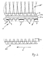
- a first exemplary embodiment of the insert mat 1 (FIG. Fig. 1 ) has an outreach as a carrier layer 2 for a decorative layer 15.
- a Verhakungs slaughter 3 is arranged on an underside of the carrier layer 2 on an underside of the carrier layer 2 is connected by means of a bonding layer (not shown in FIG FIG. 1 ) a Verhakungs slaughter 3 is arranged.
- the hooking layer 3 consists of fibers 3a.
- the hooking layer has raised areas 4 and compacted areas 5. In the area of the raised areas 4, there are irregularly free ends 6 of the fibers 3a forming the hooking layer 3.
- the Verhakungstik is a velouranalysise needle felt with a basis weight of about 200 g / m 2 up to 800 g / m 2 .
- the fibers 3a from which the velorized needle punched fleece is formed, have a fineness of 20 dtex to 100 dtex and a cut length of 30 mm to 80 mm.
- the velorized needle punched fleece is preferably shaved, but may also be unshackled with reduced adhesive force requirements.
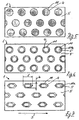
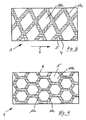
- the raised areas 4 may, for example, be islands 11 or a closed line pattern 11a, which will be described hereinafter with reference to FIGS Fig. 5 to 9 is explained in more detail.
- the islands 11 can either be distributed regularly or irregularly over the surface of the insert mat 1 in a circular shape.
- the islands 11 are circular in shape, with a center region 11b likewise forming a compacted region 5.
- the spatial shape of the islands 11 is shown as a hexagon, which have a center region 11b.
- the longitudinal extent 1 of the islands 11 in this embodiment is greater than the transverse extent b of the islands 11. If island shapes are selected which have a greater longitudinal extent 1 than the transverse extent b, then it is recommended that the longitudinal extent 1 be parallel to a line direction S of a substrate 30 to which the insert mat 1 is intended to be laid. This results in a better entanglement of the mats 1 with the pad 30th
- the raised areas 4 are arranged distributed as a closed line pattern on the underside of the insert mat 1.
- a closed line pattern in the sense of the invention means a line pattern in which all raised areas 4 of the insert mat 1 are connected to one another. This distinguishes the closed line pattern from the above-described arrangement of islands 11 on the underside of the insert mat 1.
- the under the Fig. 5 to 9 Drawings shown island and line patterns are only examples. Of course, other geometrical spatial forms, such. B.
- ovals or ovals with a center region 11a or closed line pattern 11a are performed with non-straight connecting lines or irregularly distributed over the bottom of the insert mat 1 connecting lines.
- a closed line pattern 11a as exemplified in Fig. 8 is indicated, it is recommended that at least portions of lines 11c, which form the closed line pattern, to oblique to a stroke direction S a pad on which the insert mat is to be placed, ie not necessarily at an angle of 90 ° or parallel to the direction S. This results in an increased adhesion of the mat.
- the line direction S of the car carpet (not shown) is oriented by default in the direction of travel to the rear parallel to the vehicle longitudinal axis.
- FIG. 9 shows a particularly preferred embodiment of the insert mat according to the invention, in which the raised areas 4 are formed as a closed line pattern in the form of a honeycomb structure, in particular a hexagonal honeycomb structure. It could be determined in the course of experiments that the adhesion force of such a line pattern for the raised areas 4 has the highest static friction values on a base 30 in comparison with other types of line patterns.
- acc. Fig. 10 are different geometric configurations of the islands 11 realized in different surface density distributed over the bottom of the insert mat 1.
- the insert mat 1 according to the invention has a carrier layer 2 as the first step for a decorative layer 15 from a tuft.
- the hooking layer 3 is arranged on an underside of the carrier layer 2.
- the pole loops are cut open, so that free ends 6 of the pile yarn 8 arise.
- Subareas of the interlocking layer 3 are permanently compressed and / or compressed areas 5, so that raised areas 4 remain.
- the decorative layer 15 is formed for example as Thomasflor, wherein the Thomasflor forming cut loops are tufted into the carrier layer 2.
- the free ends 6 of the pile yarn 8 of the hooking layer 3 protrude from the carrier layer 2a and thus form entanglement devices with a base 30, which can be, for example, a car carpet, which in most cases is also a tuft.
- the pad 30 usually has a line direction S, which is often directed in the vehicle longitudinal direction of a car in the direction of travel to the rear.
- the compacted regions 5 are achieved by permanent compression of free ends 6 of the pile yarn 8 and, seen in their vertical extent from the carrier layer 2, are lower than the raised regions 4, which have a greater vertical extent away from the carrier layer 2.
- the degree of compaction can be varied or the length of the free ends 6 can be set correspondingly for a given degree of compaction for the compacted regions 5. This depends essentially on the nature of the pad 30. So it is recommended, for example, the free ends 6 in a particularly low-pile car carpet (pad 30) also tend to keep their length rather small.
- the length of the free ends 6 or the protrusion t of the raised Areas 4 relative to the densified areas 5 are usefully chosen not to be larger than the pile height h of the base 30.
- the degree of compaction for producing the compacted areas must be adjusted accordingly.
- the degree of compaction can be chosen slightly lower and a corresponding projection t of the raised areas 4 with respect to the compacted areas 5 can be achieved by a greater length of the free ends 6.
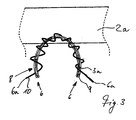
- the Verhakungs slaughter 3 is formed of a special pile yarn 8, which is based on the Fig. 3 will now be explained in more detail.
- the pile yarn 8 has a central multifilament 9 formed of a plurality of fine filaments / fibers 3a.
- a monofilament 10 is looped around the multifilament 9, wherein the composite of the multifilament 9 and the monofilament 10 is formed even before the tuft of the hooking layer 3 is produced, and the composite is tufted into the carrier layer 2a.
- tufting the pile loops formed from pile yarn 8 are cut, so that the hooking layer 3 is formed in the manner of a cut velor layer. This results in the free ends 6 of the pile yarn 8.
- the monofilament 10 is substantially thicker than the fibers 3a of the multifilament 9, there is a tendency for the monofilament 10 to unwind a bit from the multifilament 9. This results in longer free ends 6a of the monofilament 10, which have a greater stiffness than the filaments / fibers 3a of the multifilament 9. These longer and stiffer ends 6a of the monofilament, when placed on the base 30, can get caught in the base 30 well, because they can penetrate further into the pile of the base 3 due to the higher buckling resistance. This entanglement effect can be further enhanced by roughening the monofilament 10 slightly before making the composite of multifilament 9 and monofilament 10 into pile yarn 8.
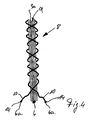
- a single monofilament 10 is wrapped around a multifilament formed of fibers / filaments 3a.
- a schematically greatly enlarged section of a pile yarn 8 is shown, in which two monofilaments 10 are looped around the multifilament 9 in the manner of a double-threaded screw.
- a multiple wrapping of the multifilament 9 with two or more monofilaments 10 accordingly, when cutting the tuft loops (pile loops), a plurality of free ends 6a of the monofilaments 10 are formed.
- two or more monofilaments 10 may be formed around the multifilament 9 into a wrapping multiple filament comprising two or more monofilaments 10 prior to wrapping, wherein the wrapping multiple filament is wrapped around the multifilament 9 as described above.
- the filaments / fibers 3a of the multifilament 9 expediently have a fineness of from 20 dtex to 80 dtex.
- the monofilament 10 or the monofilaments 10 preferably have a fineness of 40 dtex to 800 dtex.
- the process according to the invention is briefly explained below. It is distinguished, in particular, by the fact that first of all an outreach is provided as the carrier layer 2 of the insert mat 1.
- a decorative layer 15 is tufted or applied flat.
- a hooking layer 3 either a velourized needle felt (dilours) or a tuft layer with a carrier layer 2a is used.
- a velourized needle felt in the specification already explained above.
- the pile yarn 8 consists of a multifilament 9 comprising fibers / filaments 3a.
- at least one monofilament 10 is wrapped around the multifilament 9.
- the tufted pile yarn 8 of the hooking layer 3 is cut so that free pile ends 6 are formed. Subsequently, the interlocking layer is pressed in some areas and / or partially permanently compacted, so that raised, formed from pole ends 6 areas 4 of the interlocking layer 3 arise.
- the pressing and / or permanent compacting is expediently carried out after the tufting and cutting of the interlocking layer by means of a heated embossing template (not shown), which is placed on the interlocking layer 3 and provides by means of sufficient pressing pressure for the formation of the compacted and / or compressed areas 5. Pressing by means of a heated press jig is suitable both for the embodiment with a velorized needle felt and for the embodiment with a tufted hooking layer of a multifilament and optionally a monofilament as pile yarn.
- the pressing may also take place in such a way that, for example, the areas 5 to be thickened and pressed on the hooking layer 3 are pressed down and then, by means of ultrasound, a connection of the pressed fibers to each other or optionally to the carrier layer 2a is achieved.
- the monofilaments 10 are roughened around the multifilament 9 before looping, so that after cutting the pole loops after tufting free ends 6a of the monofilament 10 are formed, which have a roughened and thus tends to be verhakungsLERere surface.
- the insert mat 1 according to the invention and the method according to the invention are characterized in particular by the fact that the insert mat 1 has a particularly good adhesion to conventional carpeting trays of passenger cars and is moreover particularly cost-effective to produce since the flocking step can be saved. Furthermore, this insert mat is particularly easy to clean, since it can be easily removed again from the raised areas in use staking dirt and thus the original mint adhesive property of the mat can be restored at least approximately with conventional cleaning methods.
- the inventive method is characterized in particular by the cost feasibility. Furthermore, the embossing step provided according to the invention for compacting the hooking layer is very reliable and easy to carry out, so that low losses and a low scrap content can be expected.
Landscapes
- Engineering & Computer Science (AREA)
- Textile Engineering (AREA)
- Mechanical Engineering (AREA)
- Transportation (AREA)
- Carpets (AREA)
- Passenger Equipment (AREA)
Description
Die Erfindung betrifft eine rutschfeste Einlegematte nach dem Oberbegriff des Anspruchs 1 sowie ein Verfahren zur Herstellung der Einlegematte.The invention relates to a non-slip insert mat according to the preamble of
Bekannte Einlegematten zum Einlegen in Fußräume von Kraftfahrzeugen, insbesondere Pkws, bei denen eine Teppichbodenwanne eingebaut ist, weisen im Wesentlichen folgenden Aufbau auf.Known mats for insertion into foot wells of motor vehicles, in particular cars, in which a carpet tray is installed, have substantially the following structure.
In einer Trägerschicht ist eine Nutz-/Dekorschicht eingetuftet und in den allermeisten Fällen als Schnittfloroberfläche, d. h. mit aufgeschnittenen Tuftschleifen, ausgebildet. Auf der der Dekorseite gegenüberliegenden Seite der Trägerschicht ist ein Vlies angeordnet und flächig mit der Trägerschicht verbunden. Um eine ausreichende Haftung der Einlegematte auf der Teppichbodenwanne des Pkw zu erreichen, ist es üblich, Teilbereiche der freien Oberseite des Vlieses mit kurzen Fasern zu beflocken, so dass Haftinseln entstehen. Das Beflocken von Teilbereichen der freien Oberseite des Vlieses ist außerordentlich aufwändig und teuer. Beispielsweise müssen nach dem Aufbringen der Vliesschicht zunächst die Beflockungsfasern örtlich definiert auf dem Filz befestigt werden. Anschließend ist es erforderlich mittels elektrostatischer Aufladungsvorgänge die Fasern möglichst senkrecht vom Vlies abgehend aufzurichten. Anschließend müssen die aufgerichteten Fasern dauerhaft in der aufgerichteten Position fixiert werden. Zwar können mit einer derartigen Einlegematte die derzeit gängigen Anforderungen hinsichtlich der Haftkraft der Einlegematte auf dem Untergrund, d. h. auf dem Schnittflor der Teppichbodenwanne des Pkws erreicht werden, jedoch erfordert dies einen erheblichen Aufwand. Zum anderen kann es vorkommen, dass beispielsweise durch Verschmutzung der Unterseite der Einlegematte die Verhakungsinseln aus den kurzen, relativ feinen Fasern aus dem Beflockungsvorgang mit der Zeit die Haftkraft auf dem Schnittflor der Teppichbodenwanne des Kraftfahrzeugs einbüßen. Der Grund hierfür ist, dass die Fasern der Beflockungsinseln relativ eng beabstandet zueinander angeordnet sind und im Wesentlichen alle die gleiche Länge aufweisen. Hierdurch ist das Einlagern von Staub und Schmutz im Gebrauch der Einlegematte erleichtert, was zu einer Verminderung der Haftfähigkeit der Einlegematte auf dem Teppichboden des Kraftfahrzeugs führt. Auch eine Reinigung der mittels Beflockung hergestellten Haftinseln an üblichen Autoreinigungsstationen, beispielsweise mit zwei Bürstenwalzen, gelingt nicht immer zufriedenstellend, da der Schmutz und der Staub relativ fest zwischen den Fasern der Beflockungsinseln sitzt.In a carrier layer, a useful / decorative layer is tufted and in the vast majority of cases as Schnittfloroberfläche, ie formed with cut tuft loops. On the side opposite the decorative side of the carrier layer, a fleece is arranged and connected in a planar manner with the carrier layer. In order to achieve sufficient adhesion of the mat on the carpet tray of the car, it is common to flock portions of the free top of the web with short fibers, so that islands of liability arise. The flocking of portions of the free top of the web is extremely expensive and expensive. For example, after applying the nonwoven layer, the flocking fibers must first be fixed on the felt in a locally defined manner. Subsequently, it is necessary to raise the fibers as vertically as possible from the nonwoven fabric by means of electrostatic charging processes. Subsequently, the erected fibers must be permanently fixed in the erected position. Although it is possible with such a mat the current requirements in terms of adhesive force of the mat on the ground, ie on the Schnittflor the carpet floor of the car can be achieved, but this requires considerable effort. On the other hand, it may happen that, for example, due to contamination of the underside of the insert mat, the hooking islands from the short, relatively fine fibers from the flocking process lose the adhesive force on the cut pile of the carpet sump of the motor vehicle over time. The reason for this is that the fibers of the flocking islands are relatively closely spaced and have substantially the same length. As a result, the storage of dust and dirt in the use of the mat is facilitated, resulting in a reduction of the adhesiveness of the mat on the carpet of the motor vehicle. A cleaning of the adhesive islands produced by flocking at the usual car cleaning stations, for example with two brush rollers, is not always satisfactory, since the dirt and dust sits relatively firmly between the fibers of the flocking islands.
Aus der
Die
Aufgabe der Erfindung ist es daher, eine rutschfeste Einlegematte anzugeben, welche einerseits erhöhte Anforderungen an die Haftfähigkeit auf einem Pkw-Bodenteppich, insbesondere einem Schnittvelours-Teppich, d. h. einem Teppich, welcher oberseitig keine Schlingen aufweist, erfüllt.The object of the invention is therefore to provide a non-slip insert mat, which on the one hand increased demands on the adhesion to a car floor carpet, especially a cut velor carpet, d. H. a carpet, which has no loops on the upper side, fulfilled.
Des Weiteren sollen eine Einlegematte und ein Herstellverfahren für die Einlegematte angegeben werden, welche im Vergleich zu bekannten Einlegematten bzw. Verfahren kostengünstiger, einfacher und unkomplizierter durchführbar sind.Furthermore, an insert mat and a manufacturing method for the insert mat are to be specified, which are cost-effective, simpler and less complicated to carry out in comparison to known insert mats or methods.
Des Weiteren soll eine Einlegematte angegeben werden, welche sich von im Gebrauch unvermeidlicher Verschmutzung leicht reinigen lässt und nach dem Reinigen die ursprüngliche Haftkraft, wie sie im Neuzustand vorlag, wieder erreichen soll.Furthermore, an insert mat is to be specified, which can be easily cleaned by unavoidable contamination in use and after cleaning the original adhesive force, as it was in new condition, should reach again.
Diese Aufgaben werden mit einer Einlegematte mit den Merkmalen des Anspruchs 1 und einem Verfahren zur Herstellung der Einlegematte mit den Merkmalen des Anspruchs 14 gelöst.These objects are achieved with an insert mat having the features of
Vorteilhafte Ausführungsformen sind in den jeweils abhängigen Unteransprüchen angegeben.Advantageous embodiments are specified in the respective dependent subclaims.
Erfindungsgemäß wurde erkannt, dass eine gattungsgemäße Einlegematte mit einem Erstrücken als Trägerschicht für eine Dekorschicht und einer textilen, aus Fasern gebildeten Verhakungsschicht derart weitergebildet wird, dass die Verhakungsschicht erhabene Bereiche und verdichtete Bereiche geringerer Höhe besitzt, wobei die erhabenen Bereiche durch freie Enden der Fasern gebildet sind und die Bereiche der Verhakungsschicht geringerer Höhe, d. h. die verdichteten Bereiche durch dauerhaftes Verpressen der freien Enden der Fasern gebildet sind. Eine derartige erfindungsgemäße Einlegematte ist besonders kostengünstig in der Herstellung, da freie Enden der die Verhakungsschicht bildenden textilen Schicht zur Verhakung mit einem Teppichboden eines Kraftfahrzeugs genutzt werden. Durch das bereichsweise Verpressen der die Verhakungsschicht bildenden textilen Schicht entstehen erhabene Bereiche und verpresste Bereiche geringerer Höhe, d. h., dass in diesen Bereichen die textile Schicht, welche die Verhakungsschicht bildet, eine geringere Dicke aufweist. Hierdurch gelingt es die überstehenden Fasern der erhabenen Bereiche intensiver mit der Teppichbodenauskleidung des Kraftfahrzeugs in Kontakt zu bringen. Hierdurch entsteht ein erhöhter Verhakungsgrad, so dass schon bei geringeren Druckbelastungen der Einlegematte ein ausreichender Verhakungsgrad und somit eine gute Haftkraft auf der Pkw-Teppichbodenschicht erzielbar ist.According to the invention, it has been recognized that a generic insert mat having an initial stretch as a carrier layer for a decorative layer and a textile interlocking layer formed from fibers is developed in such a way that the interlocking layer has raised areas and compacted areas of lesser height, wherein the raised areas are formed by free ends of the fibers and the areas of the interlocking layer of lesser height, ie the compacted areas by permanent Pressing the free ends of the fibers are formed. Such a mat according to the invention is particularly inexpensive to manufacture, since free ends of the fabric layer forming the hooking layer are used for entanglement with a carpet of a motor vehicle. The partial pressing of the textile layer forming the hooking layer produces raised areas and compressed areas of lesser height, ie in these areas the textile layer which forms the hooking layer has a smaller thickness. This makes it possible to bring the protruding fibers of the raised areas more intensively with the carpet lining of the motor vehicle in contact. This results in an increased Verhakungsgrad, so that even at lower pressure loads of the mat a sufficient Verhakungsgrad and thus a good adhesion to the car carpet layer is achieved.
Gemäß einer besonders bevorzugten Ausführungsform besteht die Verhakungsschicht aus einem Tuft mit einer Trägerschicht und einem in die Trägerschicht eingetuftetem Polgarn. Die erhabenen Bereiche werden durch freie Enden des Polgarns, welches beim oder nach dem Tuften geschnitten wird, gebildet. Die Bereiche der Verhakungsschicht geringerer Höhe werden durch dauerhaftes Verpressen der freien Enden des Polgarns gebildet. Bei dieser Ausführungsform wird als Polgarn bevorzugt ein Multifilament eingesetzt, welches von zumindest einem Monofilament umschlungen ist, wobei das Monofilament im Vergleich zu dem das Multifilament bildenden Filamenten dicker ausgebildet ist.According to a particularly preferred embodiment, the hooking layer consists of a tuft with a carrier layer and a pile yarn tufted into the carrier layer. The raised areas are formed by free ends of the pile yarn which is cut during or after tufting. The portions of the interlocking layer of lesser height are formed by permanently pressing the free ends of the pile yarn. In this embodiment, the pile yarn used is preferably a multifilament, which is looped around by at least one monofilament, wherein the monofilament is made thicker in comparison with the filament forming the multifilament.
Das dickere Monofilament ist wendelartig oder schraubenartig um das Multifilament gewunden und wird mit dem Multifilament zusammen als ein Garn beim Tuften verarbeitet. Da die beim Tuften gebildeten Polschlingen aufgeschnitten werden, so dass freie Polgarnenden entstehen, kann sich im Bereich der freien Enden des Polgarns das dickere Monofilament zumindest ein Stück vom Multifilament ablösen und/oder abwickeln. Das abgewickelte/abgelöste Ende des Monofilaments ist dabei aufgrund der vormals vorliegenden Umschlingung des Multifilaments etwas länger als die freien Enden des Multifilaments. Weiterhin sind die freien Enden des Monofilaments etwas steifer und knickfester als die freien Enden der Fasern des Multifilaments. Hierdurch wird erreicht, dass die längeren, weiter vorstehenden Enden des Monofilaments tief in die Teppichstruktur des Pkw-Bodenteppichs eindringen können und somit eine besonders sichere Verhakung und eine besonders widerstandsfähige Anhaftung der Einlegematte gegen Wegrutschen ausbilden.The thicker monofilament is wound helically or helically around the multifilament and is processed with the multifilament together as a yarn during tufting. Since the pile loops formed during tufting are cut open, so that arise free pile ends, may replace the thicker monofilament at least a piece of the multifilament and / or unwind in the region of the free ends of the pile yarn. The unwound / detached end of the monofilament is slightly longer than the free ends of the multifilament due to the formerly present looping of the multifilament. Furthermore, the free ends of the monofilament are somewhat stiffer and more kink resistant than the free ends of the fibers of the multifilament. This ensures that the longer, more prominent ends of the monofilament can penetrate deep into the carpet structure of the car floor carpet and thus form a particularly secure entanglement and a particularly resistant adhesion of the mat against slipping.
Gemäß einer weiteren Ausführungsform der erfindungsgemäßen Einlegematte ist die Verhakungsschicht aus einem velourisierten Nadelvlies ausgebildet. Diese Schicht aus einem velourisierten Nadelvlies ist besonders kostengünstig aufzubringen, da die Vliesschicht flächig z.B. mit der Trägerschicht der Dekorschicht verbunden werden kann. Für die Fasern des velourisierten Nadelvlieses kommen insbesondere PET- oder PP- oder PA6- oder PA6.6-Fasern in Betracht. Ein Flächengewicht des velourisierten Nadelvlieses von 200 g/m2 bis 800 g/m2 hat sich besonders bewährt. Die Fasern, aus denen das velourisierte Nadelvlies gebildet ist, besitzen bevorzugt eine Feinheit von 20 dtex bis 100 dtex und haben eine Schnittlänge von 30 mm bis 80 mm. Das velourisierte Nadelvlies kann bevorzugt als geschorenes Nadelvlies eingesetzt werden. Ferner können zur Bildung des velourisierten Nadelvlieses eine Fasermischung unterschiedlicher Feinheit oder unterschiedlicher Schnittlänge benutzt werden.According to a further embodiment of the insert mat according to the invention the Verhakungsschicht is formed from a velourisierten needle felt. This layer of a velorized needle punched nonwoven fabric is particularly inexpensive to apply, since the nonwoven layer can be connected flat, for example, with the carrier layer of the decorative layer. PET or PP or PA6 or PA6.6 fibers are particularly suitable for the fibers of the velorized needle-punched nonwoven. A weight per unit area of the velorized needle felt of 200 g / m 2 to 800 g / m 2 has proven particularly useful. The fibers from which the velorized needle-punched fleece is formed preferably have a fineness of 20 dtex to 100 dtex and have a cutting length of 30 mm to 80 mm. The velorized needle felt can preferably be used as a shorn needle punched nonwoven. Furthermore, a fiber blend of different fineness or different cut length can be used to form the velorized needle felt.
Es ist ebenfalls möglich, Fasern aus unterschiedlichen Werkstoffen zu verwenden, beispielsweise eine Mischung aus PP- und PA-Fasern.It is also possible to use fibers of different materials, for example a mixture of PP and PA fibers.
Besonders bewährt hat sich, dass die erhabenen Bereiche auf der Unterseite der Einlegematte Inseln bilden. Hierdurch gelingt es punktuell einen erhöhten Verhakungsgrad zwischen der Einlegematte und dem darunter befindlichen Pkw-Bodenteppich zu realisieren.It has proven particularly useful that the raised areas on the underside of the insert mat form islands. This makes it possible selectively to realize an increased Verhakungsgrad between the insert mat and the underlying car floor carpet.
Gleichermaßen bewährt hat sich auch, dass die erhabenen Bereiche ein zusammenhängendes, insbesondere über die Fläche der Einlegematte zusammenhängendes, Linienmuster bilden. Für den Überstand der erhabenen Bereiche gegenüber den verpressten Bereichen der Verhakungsschicht haben sich Maße von 0,5 mm bis 3 mm, bevorzugt von 1 mm bis 2 mm, bewährt. Innerhalb dieser Bereiche besitzen die freien Enden der die erhabenen Bereiche ausbildenden Fasern noch genug Eigensteifigkeit, um ein Eindringen in die Oberseite des darunter liegenden Pkw-Teppichs zuverlässig zu gewährleisten.Equally proven has been that the raised areas form a coherent, in particular over the surface of the insert mat related, line pattern. For the supernatant of the raised areas in relation to the pressed areas of the hooking layer, dimensions of 0.5 mm to 3 mm, preferably 1 mm to 2 mm, have proved successful. Within these regions, the free ends of the fibers forming the raised regions still have enough inherent rigidity to reliably ensure penetration into the top of the underlying car carpet.
Die dauerhaft verpressten Bereiche sind bevorzugt durch thermisches Verpressen gebildet, wodurch die Filamente des Multifilaments und das umschlingende Monofilament zumindest bereichsweise miteinander verschmolzen sind und/oder die Filamente und die Monofilamente mit der Trägerschicht der Dekorschicht oder mit der Trägerschicht der Verhakungsschicht zumindest teilweise verschmolzen sind. Dies stellt eine ausreichende Dauerhaftigkeit der Verpressung und somit eine dauerhafte Ausbildung des erfindungsgemäß zu realisierenden unterseitigen Reliefs der Einlegematte dar. Als bevorzugte Relation zwischen der Dicke der Filamente, die das Multifilament bilden und dem Monofilament hat sich bewährt, das Monofilament etwa zwei- bis zehnmal, bevorzugt fünf- bis 20-mal so dick auszugestalten. Für das Multifilament und das Monofilament kommen insbesondere Fasern aus PA6, PA12, PP oder PET in Frage.The permanently pressed areas are preferably formed by thermal compression, whereby the filaments of the multifilament and the looping monofilament are at least partially fused together and / or the filaments and the monofilaments are at least partially fused with the carrier layer of the decorative layer or with the carrier layer of Verhakungsschicht. This represents a sufficient durability of the compression and thus a permanent formation of the present invention to be realized lower relief of the insert mat. As a preferred relationship between the thickness of the filaments which form the multifilament and the monofilament has been proven, the monofilament about two to ten times, preferably five to 20 times as thick. For the multifilament and the monofilament in particular fibers from PA6, PA12, PP or PET come into question.
Um die Rutschfestigkeit der Einlegematte auf dem Pkw-Teppichboden weiter zu verbessern empfiehlt es sich, die erhabenen Bereiche in Bereichen der Einlegematte mit im Gebrauch größerer Tritt- oder Druckbelastung dichter beieinander anzuordnen als in den Bereichen mit geringerer Tritt- oder Druckbelastung. In Bereichen höherer Druckbelastung, also z. B. in den Bereichen, in denen die Fahrgäste mit erhöhter Wahrscheinlichkeit die Füße auf der Einlegematte abstellen, steht im Gebrauch eine größere Flächenbelastung zur Verfügung, die ein Verhaken der freien Faserenden mit dem Pkw-Teppich bewirkt. In diesen Bereichen kann der Flächenanteil der erhabenen Bereiche relativ zu den Flächenanteilen der verpressten Bereiche größer gewählt werden. Im Bereich größerer Tritt- oder Druckbelastung kann auch der Grad der Verpressung, der gegenüber den erhabenen Bereichen zurückgesetzten Bereichen etwas geringer gewählt werden. Hierdurch entstehen im Vergleich zu einer stärkeren Verpressung mehr freie Faserenden, die nicht oder nicht ganz in den Pressverbund integriert sind, und somit gegebenenfalls auch in den verpressten Bereichen zur zusätzlichen Verhakung der Einlegematte im Pkw-Teppichboden beitragen.In order to further improve the skid resistance of the mat on the car floor, it is advisable to arrange the raised areas in areas of the mat more closely with one another during use of greater tread or pressure load than in areas with less tread or pressure load. In areas of higher pressure load, so z. As in the areas where the passengers are more likely to park their feet on the mat, in use, a larger surface load is available, causing a hooking of the free fiber ends with the car carpet. In these areas, the area ratio of the raised areas relative to the area proportions of the compressed areas can be made larger. In the area of greater tread or pressure load and the degree of compression, the recessed areas compared to the raised areas can be chosen slightly lower. This results in more free fiber ends, which are not or not fully integrated into the press assembly compared to a stronger compression and thus possibly contribute to the additional entanglement of the mat in the car carpet in the compressed areas.
Um die Verhakung und somit die Rutschfestigkeit der Einlegematte weiter zu verbessern, ist es auch zweckmäßig, die flächige Größe der erhabenen Bereiche pro Flächeneinheit der Einlegematte im Bereich der größeren Tritt- oder Druckbelastung größer zu wählen als im Bereich geringerer Druckbelastung.In order to further improve the entanglement and thus the skid resistance of the insert mat, it is also expedient to choose the areal size of the raised areas per unit area of the insert mat to be greater in the region of the greater pedaling or compressive load than in the area of lower pressure loading.
Für die Ausgestaltung der erhabenen Bereiche kommen bevorzugt kreis-, kreisring-, oval- oder drei- oder mehreckig oder unregelmäßig geformte Inselkonturen in Betracht. Bei geschlossenen Linienmustern hat sich ein wabenartiges Linienmuster besonders bewährt.For the configuration of the raised areas are preferably circular, circular, oval or triangular or polygonal or irregularly shaped island contours into consideration. When closed Line patterns have proven to be a honeycomb line pattern particularly.
Besonders bewährt hat sich, dass zumindest zwei Monofilamente das Multifilament nach Art einer zwei- oder mehrgängigen Schraube umschlingen. Hierdurch wird die Anzahl der längeren freien Enden des Monofilaments pro Flächeneinheit erhöht, was zu einer verbesserten Rutschfestigkeit führt. Ein gleicher Effekt der verbesserten Rutschfestigkeit kann erzielt werden, wenn zwei Monofilamente zu einem Umschlingungsmehrfachfilament verdrillt sind und das Umschlingungsmehrfachfilament schraubenartig um das Multifilament des Polgarns geschlungen ist. Auch können mehrere Umschlingungsmehrfachfilamente um ein Multifilament des Polgarns geschlungen sein. Durch eine derartige Ausgestaltung entsteht eine Vielzahl von längeren, überstehenden freien Enden des Monofilaments, welche sich in der Pkw-Teppichstruktur gut verhaken können.It has proven particularly useful that at least two monofilaments wrap around the multifilament in the manner of a two- or multi-start screw. This increases the number of longer free ends of the monofilament per unit area, resulting in improved slip resistance. An equal effect of improved skid resistance can be obtained when two monofilaments are twisted into a wrapping multiple filament and the wrapping multiple filament is helically wound around the multifilament of the pile yarn. Also, several wrapping multiple filaments may be looped around a multifilament of the pile yarn. By such a configuration, a plurality of longer, protruding free ends of the monofilament, which can get caught in the car carpet structure well.
Weiterhin konnte festgestellt werden, dass bei einer gegebenen Gewichtsbelastung der Einlegematte die Rutschfestigkeit der Einlegematte optimal ist, wenn der flächige Anteil der erhabenen Bereiche kleiner oder höchstens gleich groß ist wie der flächige Anteil der verpressten Bereiche der Einlegematte.Furthermore, it has been found that for a given weight load of the insert mat, the slip resistance of the insert mat is optimal if the areal proportion of the raised areas is smaller or at most equal to the areal proportion of the pressed areas of the insert mat.
Ein erfindungsgemäßes Verfahren zeichnet sich insbesondere dadurch aus, dass auf eine Trägerschicht einer Dekorschicht zunächst eine Verhakungsschicht aufgebracht wird, welche zumindest bereichsweise lokal dauerhaft verpresst wird, so dass erhabene Bereiche mit freien Fasern und verpresste Bereiche niedriger Höhe gebildet werden. Gemäß einer ersten Alternative wird als Verhakungsschicht eine Dilours-Nadelvliesschicht verwendet und die Verpressung erfolgt unter Einsatz von Wärme oder Ultraschall. Gemäß einer zweiten Alternative des erfindungsgemäßen Verfahrens wird die Verhakungsschicht auf zumindest einer Seite der Trägerschicht durch Tuften eines Polgarns in eine Trägerschicht der Verhakungsschicht hergestellt, wobei als Polgarn ein Garn aus einem Multifilament verwendet wird und wobei das getuftete Polgarn geschnitten wird, so dass freie Polenden entstehen. Anschließend werden die freien Polenden teilbereichsweise verpresst und/oder dauerhaft verdichtet, so dass erhabene aus Polenden gebildete Bereiche der Verhakungsschicht entstehen. Für das bereichsweise Verpressen und/oder dauerhafte Verdichten hat sich eine Pressung mittels einer beheizten Pressschablone, welche die erhabenen Bereiche von der Verpressung ausnimmt, bewährt. Hierdurch werden die die Verhakungsschicht bildenden Fasern in den verpressten Bereichen zumindest teilweise miteinander verschmolzen und so dauerhaft verpresst. Gleichwohl eignet sich zum Verpressen und/oder dauerhaften Verdichten auch Ultraschall, der im Zusammenspiel mit einer Pressschablone eine dauerhafte Verbindung der Fasern in den verpressten Bereichen bewirkt.A method according to the invention is characterized in particular by first applying to a carrier layer of a decorative layer an interlocking layer which is at least locally locally permanently compressed so that raised areas with free fibers and compressed areas of low height are formed. According to a first alternative, a diloured needle-punched non-woven layer is used as the interlocking layer and the compression takes place using heat or ultrasound. According to a second alternative of the method according to the invention, the interlocking layer is at least one side of the carrier layer is produced by tufting a pile yarn into a carrier layer of the hooking layer, wherein a yarn of a multifilament is used as pile yarn and wherein the tufted pile yarn is cut so that free pile ends are formed. Subsequently, the free pole ends are partially compressed and / or permanently compressed, so that raised areas formed of pole ends of the interlocking layer arise. For the pressing in sections and / or permanent compaction, a pressing by means of a heated pressing template, which excludes the raised areas of the pressing, has proven. As a result, the fibers forming the hooking layer are at least partially fused together in the pressed areas and thus permanently compressed. Nevertheless, ultrasound is also suitable for pressing and / or permanent compacting which, in interaction with a pressing template, effects a permanent connection of the fibers in the compressed areas.
Bevorzugt wird als Polgarn ein Garn aus einem Multifilament und zumindest einem das Multifilament umschlingenden Monofilament verwendet. Das Monofilament ist dicker ausgebildet als die das Multifilament bildenden Fasern/Filamente.Preferably, a yarn of a multifilament and at least one monofilament wrapping around the multifilament is used as the pile yarn. The monofilament is made thicker than the multifilament forming fibers / filaments.
Weitere vorteilhafte Ausführungsformen sind in weiteren Unteransprüchen sowohl hinsichtlich des Verfahrens als auch hinsichtlich der Einlegematte angegeben.Further advantageous embodiments are specified in further subclaims, both with regard to the method and with regard to the insert mat.
Im Folgenden wird die Erfindung anhand der Zeichnung beispielhaft näher erläutert. Es zeigen:
- Figur 1:
- eine erste Alternative der erfindungsgemäßen Einlegematte in einem stark schematisierten Querschnitt;
- Figur 2:
- eine zweite Alternative der erfindungsgemäßen Einlegematte in einem stark schematisierten Querschnitt;
- Figur 3:
- ein Detail X aus
Fig. 1 ; - Figur 4:
- eine vergrößerte Darstellung (stark schematisiert) eines Polgarns zur Ausbildung der Einlegematte gemäß
Fig. 2 ;bis 3 - Figur 5:
- eine weitere Ausführungsform der erfindungsgemäßen Einlegematte aufweisend Haftinseln in Kreisform;
- Figur 6:
- eine weitere Ausführungsform der erfindungsgemäßen Einlegematte aufweisend Haftinseln in Kreisringform;
- Figur 7:
- eine weitere Ausführungsform der erfindungsgemäßen Einlegematte mit Haftinseln in einer Sechseckausführung;
- Figur 8:
- die erfindungsgemäße Einlegematte in einer weiteren Ausführungsform mit Haftbereichen in Form von geschlossenen Linienzügen/Linienmustern;
- Figur 9:
- die erfindungsgemäße Einlagematte mit Haftungsbereichen in Form eines geschlossenen Wabenmusters;
- Figur 10:
- eine weitere Ausführungsform der erfindungsgemäßen Einlegematte mit über die Haftoberfläche der Einlegematte, d. h. die Unterseite der Einlegematte, ungleichmäßig verteilt angeordneten Haftinseln.
- FIG. 1:
- a first alternative of the insert mat according to the invention in a highly schematic cross section;
- FIG. 2:
- a second alternative of the insert mat according to the invention in a highly schematic cross section;
- FIG. 3:
- a detail X out
Fig. 1 ; - FIG. 4:
- an enlarged view (highly schematic) of a pile yarn to form the mat according to
Fig. 2 to 3 ; - FIG. 5:
- a further embodiment of the invention Einlegematte having adhesive islands in a circular shape;
- FIG. 6:
- a further embodiment of the invention Einlegematte adhesive islands in circular ring shape;
- FIG. 7:
- a further embodiment of the invention Einlegematte with Haftinseln in a hexagonal design;
- FIG. 8:
- the insert mat according to the invention in a further embodiment with adhesive areas in the form of closed Linienügen / line patterns;
- FIG. 9:
- the insert mat according to the invention with adhesion areas in the form of a closed honeycomb pattern;
- FIG. 10:
- a further embodiment of the insert mat according to the invention with over the adhesive surface of the insert mat, ie the underside of the insert mat, unevenly distributed prying islands.
Ein erstes Ausführungsbeispiel der erfindungsgemäßen Einlegematte 1 (
Die Inseln 11 (
Bei einer Ausführungsform gem.
Bei einer Ausführungsform gem.
Bei einer Ausführungsform gem.
Besonders vorteilhaft ist es, in Bereichen, in denen im Gebrauch mit einer erhöhten Tritt- oder Druckbelastung zu rechnen ist, beispielsweise in einem Bereich, in dem eine größere Wahrscheinlichkeit herrscht, dass Füße der Fahrgäste abgestellt sind, etwas dichter anzuordnen als in Bereichen mit einer im Gebrauch geringeren Tritt- oder Druckbelastung. Ein Bereich im Gebrauch geringerer Druck- oder Trittbelastung ist beispielsweise derjenige Bereich einer Einlegematte 1, der in einem hinteren Fußraum eines Pkw verlegt wird und dort ein Stück unter den Sitz des Vordersitzes hineinragt. In diesem Bereich können im Gebrauch nur geringere Druck- oder Trittbelastungen auftreten, so dass über die Fläche verteilt eine geringere Dichte der erhabenen Bereiche zweckmäßig ist, damit diese durch die geringere Belastung, insbesondere bereits durch das Eigengewicht der Einlegematte 1 gut verhaken können.It is particularly advantageous in areas in which an increased tread or pressure load is to be expected in use, for example in an area in which there is a greater likelihood that the feet of the passengers are parked, to arrange somewhat denser than in areas with one in use less tread or pressure load. An area in the use of lower pressure or tread load, for example, that portion of an
Eine zweite Alternative der erfindungsgemäßen Einlegematte wird im Folgenden anhand der
Es hat sich bewährt, die erhabenen Bereiche 4 etwa 0,5 mm bis 3 mm, insbesondere 1 mm bis 2 mm über die verdichteten Bereiche 5 überstehen zu lassen. Um dies zu erreichen, kann entweder der Grad der Verdichtung variiert werden oder die Länge der freien Enden 6 bei vorgegebenem Verdichtungsgrad für die verdichteten Bereiche 5 entsprechend eingerichtet werden. Dies hängt im Wesentlichen von der Beschaffenheit der Unterlage 30 ab. So empfiehlt es sich, z.B. die freien Enden 6 bei einem besonders niederflorigen Pkw-Teppich (Unterlage 30) ebenfalls in ihrer Länge eher klein zu halten. Beispielsweise sollte die Länge der freien Enden 6 oder der Überstand t der erhabenen Bereiche 4 gegenüber der verdichteten Bereiche 5 sinnvollerweise nicht größer gewählt werden als die Florhöhe h der Unterlage 30. Um einen entsprechenden Überstand t zwischen den erhabenen Bereichen 4 und den verdichteten Bereichen 5 zu erreichen, muss der Verdichtungsgrad zur Herstellung der verdichteten Bereiche entsprechend eingestellt werden.It has proven useful to let the raised
Bei höherflorigen Unterlagen kann der Verdichtungsgrad etwas geringer gewählt werden und ein entsprechender Überstand t der erhabenen Bereiche 4 gegenüber den verdichteten Bereichen 5 durch eine größere Länge der freien Enden 6 erreicht werden.For higher piled documents, the degree of compaction can be chosen slightly lower and a corresponding projection t of the raised
Die Verhakungsschicht 3 ist aus einem speziellen Polgarn 8 gebildet, welches anhand der
Im Ausführungsbeispiel gem.
Gemäß einer weiteren Ausführungsform (nicht gezeigt) können zwei oder mehrere Monofilamente 10 vor dem Umschlingen um das Multifilament 9 zu einem zwei oder mehrere Monofilamente 10 aufweisenden Umschlingungsmehrfachfilament ausgebildet werden, wobei dann das Umschlingungsmehrfachfilament um das Multifilament 9 wie oben beschrieben geschlungen ist.According to another embodiment (not shown), two or
Die Filamente/Fasern 3a des Multifilaments 9 weisen zweckmäßigerweise eine Feinheit von 20 dtex bis 80 dtex auf. Das Monofilament 10 oder die Monofilamente 10 weisen bevorzugt eine Feinheit von 40 dtex bis 800 dtex auf.The filaments / fibers 3a of the multifilament 9 expediently have a fineness of from 20 dtex to 80 dtex. The
Um die Verhakung der freien Enden 6a der Monofilamente in der Unterlage 30 weiter zu verbessern ist es sinnvoll, die freien Enden 6a wie auch die freien Enden 6 im Bereiche der erhabenen Bereiche 4 einer kurzen Wärmebehandlung zu unterziehen, so dass ein bereichsweises Anschmelzen und tropfenartiges Verdicken der Enden 6a und 6 erzielt wird. Diese endseitigen Verdickungen 14 sorgen beim Eintauchen und beim Verhaken in der Unterlage 30 für eine weiter erhöhte Haftfestigkeit, insbesondere dadurch, dass die Verdickungen mit bloßen Augen zwar tropfenförmig aussehen, jedoch feine Verhakungsunebenheiten aufweisen und somit eine erhöhte Verhakung mit der Unterlage 30 erreichbar ist.In order to further improve the entanglement of the free ends 6a of the monofilaments in the
Die bereits beschriebenen möglichen Ausführungsformen der erhabenen Bereiche 4 im Vergleich zu den verdichteten Bereichen 5, welche im Zusammenhang mit der ersten Alternative gem.
Das erfindungsgemäße Verfahren wird im Folgenden kurz erläutert. Es zeichnet sich insbesondere dadurch aus, dass zunächst ein Erstrücken als Trägerschicht 2 der Einlegematte 1 zur Verfügung gestellt wird. In diesem Erstrücken wird eine Dekorschicht 15 eingetuftet oder flächig aufgebracht. Als Verhakungsschicht 3 wird entweder ein velourisiertes Nadelvlies (Dilours) oder eine Tuftschicht mit einer Trägerschicht 2a verwendet: Bei einem flächigen Aufbringen empfiehlt sich insbesondere die Verwendung eines velourisiertes Nadelvlieses in oben bereits erläuterter Spezifikation. Bei der Verwendung eines Tufts als Verhakungsschicht 3 besteht das Polgarn 8 aus einem Fasern/Filamente 3a aufweisenden Multifilament 9. Bevorzugt ist um das Multifilament 9 zumindest ein Monofilament 10 herumgeschlungen. Das getuftete Polgarn 8 der Verhakungsschicht 3 wird geschnitten, so dass freie Polenden 6 entstehen. Anschließend wird die Verhakungsschicht teilbereichsweise verpresst und/oder teilbereichsweise dauerhaft verdichtet, so dass erhabene, aus Polenden 6 gebildete Bereiche 4 der Verhakungsschicht 3 entstehen. Das Verpressen und/oder dauerhafte Verdichten geschieht zweckmäßigerweise nach dem Tuften und Schneiden der Verhakungsschicht mittels einer beheizten Prägeschablone (nicht gezeigt), welche auf die Verhakungsschicht 3 aufgesetzt wird und mittels ausreichendem Pressdruck für die Ausbildung der verdichteten und/oder verpressten Bereiche 5 sorgt. Ein Verpressen mittels einer beheizten Pressschablone ist sowohl für die Ausführungsform mit einem velourisierte Nadelvlies als auch für die Ausführungsform mit einer getufteten Verhakungsschicht aus einem Multifilament und gegebenenfalls einem Monofilament als Polgarn geeignet.The process according to the invention is briefly explained below. It is distinguished, in particular, by the fact that first of all an outreach is provided as the
Das Verpressen kann auch derart erfolgen, dass beispielsweise mit einer Pressschablone die zu verdickenden und zu verpressenden Bereiche 5 auf der Verhakungsschicht 3 niedergedrückt werden und anschließend mittels Ultraschall eine Verbindung der niedergedrückten Fasern zueinander oder gegebenenfalls zur Trägerschicht 2a erreicht wird.The pressing may also take place in such a way that, for example, the
Zweckmäßigerweise werden die Monofilamente 10 vor dem Umschlingen um das Multifilament 9 gerauht, so dass nach dem Schneiden der Polschlaufen nach dem Tuften freie Enden 6a des Monofilaments 10 entstehen, welche eine gerauhte und somit tendenziell verhakungsfreundlichere Oberfläche besitzen.Conveniently, the
Besonders zweckmäßig ist es, freie Enden 6a der Monofilamente 10 und des Multifilaments 9 kurzzeitig anzuschmelzen, so dass eine endseitige Verdickung 14 gebildet wird, welche sich besonders gut in der Unterlage 30, beispielsweise einer Teppichbodenwanne eines Pkws verhaken. Ein derartiges kurzzeitiges Anschmelzen kann beispielsweise mittels Heißluft erfolgen oder mittels einer zur oben erwähnten Pressschablone korrespondierenden zweiten Pressschablone, welche beheizt ist und nur soweit auf die Verhakungsschicht 3 aufgesetzt wird, bis die freien Enden 6, 6a der Multifilamente 9 und des Monofilaments 10 berührt werden und angeschmolzen werden.It is particularly expedient to melt free ends 6a of the
Die erfindungsgemäße Einlegematte 1 und das erfindungsgemäße Verfahren zeichnen sich insbesondere dadurch aus, dass die Einlegematte 1 eine besonders gute Haftfähigkeit auf üblichen Teppichbodenwannen von Pkws besitzt und zudem besonders kostengünstig herstellbar ist, da der Beflockungsschritt eingespart werden kann. Des Weiteren ist diese Einlegematte besonders leicht zu reinigen, da sich im Gebrauch festsetzender Schmutz aus den erhabenen Bereichen leicht wieder entfernen lässt und somit die ursprüngliche neuwertige Hafteigenschaft der Einlegematte zumindest annähernd mit üblichen Reinigungsmethoden wieder hergestellt werden kann.The
Das erfindungsgemäße Verfahren zeichnet sich insbesondere durch die kostengünstige Durchführbarkeit aus. Des Weiteren ist der erfindungsgemäß vorgesehene Prägeschritt zum Verdichten der Verhakungsschicht sehr prozesssicher und einfach durchführbar, so dass mit geringen Ausfällen und einem geringem Ausschussanteil gerechnet werden kann.The inventive method is characterized in particular by the cost feasibility. Furthermore, the embossing step provided according to the invention for compacting the hooking layer is very reliable and easy to carry out, so that low losses and a low scrap content can be expected.
- 11
- Einlegematteinlay mat
- 22
-
Trägerschicht der Dekorschicht 15Carrier layer of the
decorative layer 15 - 2a2a
-
Trägersicht der Verhakungsschicht 3Supporting view of the hooking
layer 3 - 2b2 B
- Verbindungsschichtlink layer
- 33
- VerhakungsschichtVerhakungsschicht
- 3a3a
- Fasern/FilamenteFibers / filaments
- 44
- erhabene Bereichesublime areas
- 55
- verdichtete und/oder verpresste Bereichecompacted and / or compressed areas
- 66
- freie Endenfree ends
- 6a6a
-
längere freie Enden des Monofilaments 10longer free ends of the
monofilament 10 - 77
- verlourisiertes NadelvliesVerlourisierte needle fleece
- 88th
- Polgarnpile yarn
- 99
- Multifilamentmultifilament
- 1010
- Monofilamentmonofilament
- 1111
- InselnIslands
- 11a11a
- geschlossenes Linienmusterclosed line pattern
- 11b11b
- Zentrumsbereichcenter area
- 11c11c
- Linienabschnitteline segments
- 1414
- tropfenartige Verdickungdrop-like thickening
- 1515
- Dekorschichtdecorative layer
- 3030
- Unterlagedocument
- ll
-
Längserstreckung der Inseln 11Longitudinal extension of the
islands 11 - bb
-
Längserstreckung der Inseln 11Longitudinal extension of the
islands 11 - SS
- Strichrichtungline direction
- tt
- ÜberstandGot over
- hH
- FlorhöhePile height
Claims (17)
- An anti-slip insert mat with a backing layer (2, 2a) and a textile hooking layer (3), which is composed of filaments/fibers (3a), which when used as intended, is oriented toward an underlying support (30), in particular a passenger vehicle carpet, and is embodied so that it is able to hook into the latter, characterized in that the hooking layer (3) has raised regions (4) and compacted regions (5) of lower height, with the raised regions (4) being composed of free ends (6, 6a) of the fibers (3a) and the compacted regions (5) of the hooking layer (3) being produced by permanent compression of the free ends (6, 6a) of the fibers (3a).
- The insert mat as recited in claim 1, characterized in that the hooking layer (3) is a tuft with a backing layer (2a) into which a pile yarn (8) is tufted, with the raised regions (4) being composed of free ends (6, 6a) of the pile yarn (8), the compacted regions (5) of the hooking layer (3) being produced by permanent compression of the free ends (6, 6a) of the pile yarn (8), and the pile yarn (8) being composed of a multifilament (9).
- The insert mat as recited in claim 2, characterized in that at least one monofilament (10) is wound around the multifilament (9), with the monofilament (10) being embodied as thicker than the fibers/filaments (3a) composing the multifilament (9).
- The insert mat as recited in claim 1, characterized in that the hooking layer (3) is composed of a velourized needle punched nonwoven (7), the fibers of the hooking layer (3) are composed of PET and/or PP and/or PA6 and/or PA6.6, and the velourized needle punched nonwoven (7) has a weight per unit area of 200 g/m2 to 800 g/m2.
- The insert mat as recited in one of the preceding claims, characterized in that the raised regions (4) form islands (11).
- The insert mat as recited in one of the preceding claims, characterized in that the raised regions (4) form a closed linear pattern (11a), particularly in the form of a hexagonal honeycomb pattern.
- The insert mat as recited in one of claims 2 through 6, characterized in that the permanently compacted regions (5) are produced by means of thermal compression and the filaments (3a) of the multifilament (9) and/or the winding monofilament (10) are fused to one another at least in some regions and/or the filaments (3a) and/or the monofilaments (10) are at least partially fused to one another and to the backing layer (2a).
- The insert mat as recited in one of claims 3 through 7, characterized in that the thickness of the monofilament (10) is at least two to ten times, preferably at least five to twenty times that of the filaments (3a) of the multifilament (9).
- The insert mat as recited in one of the preceding claims, characterized in that in regions of the insert mat (1) that are subjected to greater stepping pressure or compressive load during use, the raised regions (4) are positioned closer together than they are in regions that are subjected to less stepping pressure or compressive load.
- The insert mat as recited in one of the preceding claims, characterized in that in regions that are subjected to greater stepping pressure or compressive load, the degree of compaction is less than it is in regions that are subjected to less stepping pressure or compressive load.
- The insert mat as recited in one of the preceding claims, characterized in that in the region that is subjected to greater stepping pressure or compressive load, the size in area of the raised regions (4) is greater per unit area than it is in the region that is subjected to less stepping pressure or compressive load.
- The insert mat as recited in one of claims 3 through 11, characterized in that at least two monofilaments (10) are wound around the multifilament (9) in a manner that resembles a two-threaded or multi-threaded screw.
- The insert mat as recited in one of claims 3 through 12, characterized in that at least two monofilaments (10) form a winding multifilament that is wound around the multifilament (9) and in particular, several winding multifilaments are wound around the multifilament (9).
- A method for producing an anti-slip insert mat (1), composed of the following steps:- preparation of a backing layer (2, 2a) of a hooking layer (3) of the insert mat (1),- production of a hooking layer (3) on at least one side of the backing layer (2, 2a) by tufting a pile yarn (8) or mounting a layer of velourized needle punched nonwoven (7) to the entire surface,- use of a pile yarn (8), which is composed of a multifilament (9), with the tufted pile yarn (8) being cut to produce free pile ends (6, 6a) or- use of a velourized needle punched nonwoven (7) to form the hooking layer (3),- compression and/or permanent compaction of subregions (5) of the hooking layer (3) in a manner that produces raised regions (4) of the hooking layer (3), composed of pile ends (6, 6a) of the pile yarn (8) or free fibers (3a) of the velourized needle punched nonwoven (7).
- The method as recited in claim 14, characterized in that a multifilament (9) is used as the pile yarn (8) and has at least one monofilament (10) wound around it, said monofilament (10) being embodied as thicker than a fiber/filament (3a) of the multifilament.
- The method as recited in claim 14 or 15, characterized in that the compression in some regions and/or permanent compaction is produced through the application of heat by means of a heated pressing template or the compression and/or permanent compaction is produced by means of ultrasound and pressing with a pressing template.
- The method as recited in one of claims 15 through 16, characterized in that in the raised regions (4), free ends (6, 6a) of the monofilaments (10) and of the multifilament (9) are subjected to a brief partial melting, producing thickenings (14) at the ends and the brief partial melting is produced by means of hot air or the brief partial melting is produced by means of a heated plate, which is placed onto the free pile ends (6, 6a) or the free ends of the fibers of the velourized needle punched nonwoven, touching them, but not deforming them or only deforming them to an insignificant degree.
Applications Claiming Priority (2)
| Application Number | Priority Date | Filing Date | Title |
|---|---|---|---|
| DE102009040761A DE102009040761A1 (en) | 2009-09-09 | 2009-09-09 | Non-slip insert mat and method of manufacturing the insert mat |
| PCT/EP2010/062581 WO2011029736A1 (en) | 2009-09-09 | 2010-08-27 | Anti-slip insert mat and method for producing said insert mat |
Publications (2)
| Publication Number | Publication Date |
|---|---|
| EP2475813A1 EP2475813A1 (en) | 2012-07-18 |
| EP2475813B1 true EP2475813B1 (en) | 2013-10-16 |
Family
ID=42799717
Family Applications (1)
| Application Number | Title | Priority Date | Filing Date |
|---|---|---|---|
| EP10751598.3A Not-in-force EP2475813B1 (en) | 2009-09-09 | 2010-08-27 | Anti-slip insert mat and method for producing said insert mat |
Country Status (6)
| Country | Link |
|---|---|
| US (1) | US20120235438A1 (en) |
| EP (1) | EP2475813B1 (en) |
| DE (1) | DE102009040761A1 (en) |
| ES (1) | ES2439546T3 (en) |
| MX (1) | MX2012002598A (en) |
| WO (1) | WO2011029736A1 (en) |
Cited By (1)
| Publication number | Priority date | Publication date | Assignee | Title |
|---|---|---|---|---|
| US20120321877A1 (en) * | 2011-06-16 | 2012-12-20 | International Automotive Components Group North America, Inc. | Textile Structure With Improved Backing |
Families Citing this family (8)
| Publication number | Priority date | Publication date | Assignee | Title |
|---|---|---|---|---|
| US20120207959A1 (en) * | 2011-02-14 | 2012-08-16 | Protocollo Gina M | Pet paw magic mat |
| DE102012104656A1 (en) * | 2012-05-30 | 2013-12-19 | Ideal Automotive Oelsnitz Gmbh | Insert mat for motor vehicles for placement on a floor carpet structure of the motor vehicle |
| DE102013012070B4 (en) * | 2013-07-19 | 2017-12-07 | Aunde Kulmbach Gmbh | Substructure for a doormat |
| US10774612B2 (en) | 2015-04-28 | 2020-09-15 | Thru Tubing Solutions, Inc. | Flow control in subterranean wells |
| CN105078173A (en) * | 2015-08-06 | 2015-11-25 | 上海卡比特家饰地毯有限公司 | Two-in-one carpet |
| KR101789023B1 (en) * | 2017-05-02 | 2017-10-23 | 한국특수섬유기술 (주) | Footbed Mat for Cars having Anti-skid Function |
| CN111634083B (en) * | 2020-05-17 | 2022-01-25 | 杭州一胜布艺有限公司 | Method for manufacturing weft plain velvet parasitically compounded on four-side elastic fabric |
| FR3128722B1 (en) * | 2021-10-29 | 2023-09-22 | Faurecia Automotive Ind | Process for manufacturing interior coverings from a sandwich structure |
Family Cites Families (12)
| Publication number | Priority date | Publication date | Assignee | Title |
|---|---|---|---|---|
| US4902465A (en) * | 1988-07-11 | 1990-02-20 | Milliken Research Corporation | Process for forming dust control mat with non-cleated borders |
| US5616200A (en) * | 1992-10-23 | 1997-04-01 | Interface, Inc. | I-bond method for making fusion-bonded carpet |
| DE9309926U1 (en) * | 1993-07-03 | 1993-09-02 | Schaeffler Teppichboden GmbH, 96052 Bamberg | Doormat |
| US6468622B1 (en) * | 1994-04-29 | 2002-10-22 | Kleen-Tex Industries Inc. | Track control mat and method of making the same |
| US6106921A (en) * | 1998-03-03 | 2000-08-22 | Quill-Tuft, Inc. | Floor matting and yarn for its manufacture |
| DE20120605U1 (en) * | 2001-12-20 | 2002-04-18 | IDEAL Automotive GmbH, 96052 Bamberg | Interior trim part, in particular for motor vehicles |
| AU2003291160A1 (en) * | 2002-11-29 | 2004-06-23 | Swz, Llc | Textured composite material |
| WO2005049913A1 (en) * | 2003-11-14 | 2005-06-02 | Johann Borgers Gmbh & Co. Kg | Floor or wall covering for a textile base, especially in vehicles |
| ATE387877T1 (en) * | 2004-07-15 | 2008-03-15 | Domo Nv | NON-SLIP COVER |
| DE102005025681A1 (en) | 2005-06-03 | 2006-12-07 | Ideal Automotive Gmbh | Single-layer interior trim part |
| DE102005037572A1 (en) * | 2005-08-09 | 2007-02-15 | Ideal Automotive Gmbh | Covering part, in particular Innenverkleidungs- or lining part for motor vehicles |
| US20070207286A1 (en) * | 2006-03-06 | 2007-09-06 | Craig Stephen M | Floor covering having thermally modified patterned textile layer |
-
2009
- 2009-09-09 DE DE102009040761A patent/DE102009040761A1/en not_active Withdrawn
-
2010
- 2010-08-27 US US13/395,163 patent/US20120235438A1/en not_active Abandoned
- 2010-08-27 WO PCT/EP2010/062581 patent/WO2011029736A1/en not_active Ceased
- 2010-08-27 EP EP10751598.3A patent/EP2475813B1/en not_active Not-in-force
- 2010-08-27 MX MX2012002598A patent/MX2012002598A/en active IP Right Grant
- 2010-08-27 ES ES10751598.3T patent/ES2439546T3/en active Active
Cited By (2)
| Publication number | Priority date | Publication date | Assignee | Title |
|---|---|---|---|---|
| US20120321877A1 (en) * | 2011-06-16 | 2012-12-20 | International Automotive Components Group North America, Inc. | Textile Structure With Improved Backing |
| US9227543B2 (en) * | 2011-06-16 | 2016-01-05 | International Automotive Components Group North America, Inc. | Textile structure with improved backing |
Also Published As
| Publication number | Publication date |
|---|---|
| WO2011029736A1 (en) | 2011-03-17 |
| US20120235438A1 (en) | 2012-09-20 |
| MX2012002598A (en) | 2012-06-25 |
| DE102009040761A1 (en) | 2011-03-10 |
| EP2475813A1 (en) | 2012-07-18 |
| ES2439546T3 (en) | 2014-01-23 |
| WO2011029736A9 (en) | 2011-04-28 |
Similar Documents
| Publication | Publication Date | Title |
|---|---|---|
| EP2475813B1 (en) | Anti-slip insert mat and method for producing said insert mat | |
| DE10225072C1 (en) | Automobile floor covering has a carrier for pile tufts, where the longitudinal rows are secured by a zigzag back-stitching, and the lateral rows have alternating tufts and empty perforations | |
| EP1794361B1 (en) | Foam-laminated carpet shaped part for motor vehicles and method for the production thereof | |
| EP0763418A2 (en) | Method for producing a multilayered web for upholstery cover material for vehicles | |
| EP2855143B1 (en) | Insert mat for motor vehicles for laying on a floor carpet structure of the motor vehicle | |
| EP3058120B1 (en) | Clothing carrier | |
| DE2050273A1 (en) | Terrycloth with open loops, as well as method and device for the production of the same | |
| EP1587978A1 (en) | Textile fabric and method for the production and use thereof | |
| EP0959731B1 (en) | Foam moulding with an anchoring element buried in the foam | |
| WO2020148147A1 (en) | Motor vehicle floor covering, boot or trunk covering or load compartment covering having a structurally needle-punched carpet surface (ii) | |
| DE2050595A1 (en) | Car mat - from needled synthetic fibre felt | |
| DE10132103C1 (en) | Process for the production of a patterned textile fabric | |
| DE602005005210T2 (en) | NON-SLIP FAIRING | |
| EP3911792B1 (en) | Covering for the floor, boot, trunk or load compartment of a motor vehicle having a structurally needle-punched carpet surface | |
| DE2544033C3 (en) | Carpet underlay | |
| WO2020148145A1 (en) | Motor vehicle floor covering, boot or trunk covering or load compartment covering having a structurally needle-punched carpet surface | |
| DE10164087B4 (en) | Use of a nonwoven fabric with Faserpolschicht as decorative nonwoven fabric for vehicle roof lining | |
| DE10259554B3 (en) | Scouring body and process for its manufacture | |
| DE102007050874A1 (en) | Textile laminate for strip material of diaper e.g. baby diaper, fastener, has elastic support layer, and non-woven covering layer arranged on support layer, where support layer has support non-woven from thermoplastic elastomer | |
| DE102020122215A1 (en) | Fleece with a grooved structure, intermediate product and process for the production of a fleece with a grooved structure | |
| DE29603229U1 (en) | Wipers with collecting layer | |
| DE202005009135U1 (en) | Loose non-slip floor mat, to be laid on an automobile floor carpet, has a pile weave with pile loops on the upper side and a warp knit under side in a laminated structure gripping the floor carpet without additional fasteners | |
| CH711781B1 (en) | Set. | |
| DE20321620U1 (en) | Textile product with outstanding fiber structure on at least one surface side |
Legal Events
| Date | Code | Title | Description |
|---|---|---|---|
| PUAI | Public reference made under article 153(3) epc to a published international application that has entered the european phase |
Free format text: ORIGINAL CODE: 0009012 |
|
| 17P | Request for examination filed |
Effective date: 20120314 |
|
| AK | Designated contracting states |
Kind code of ref document: A1 Designated state(s): AL AT BE BG CH CY CZ DE DK EE ES FI FR GB GR HR HU IE IS IT LI LT LU LV MC MK MT NL NO PL PT RO SE SI SK SM TR |
|
| DAX | Request for extension of the european patent (deleted) | ||
| GRAP | Despatch of communication of intention to grant a patent |
Free format text: ORIGINAL CODE: EPIDOSNIGR1 |
|
| INTG | Intention to grant announced |
Effective date: 20130516 |
|
| GRAS | Grant fee paid |
Free format text: ORIGINAL CODE: EPIDOSNIGR3 |
|
| GRAA | (expected) grant |
Free format text: ORIGINAL CODE: 0009210 |
|
| AK | Designated contracting states |
Kind code of ref document: B1 Designated state(s): AL AT BE BG CH CY CZ DE DK EE ES FI FR GB GR HR HU IE IS IT LI LT LU LV MC MK MT NL NO PL PT RO SE SI SK SM TR |
|
| REG | Reference to a national code |
Ref country code: GB Ref legal event code: FG4D Free format text: NOT ENGLISH |
|
| REG | Reference to a national code |
Ref country code: CH Ref legal event code: EP |
|
| REG | Reference to a national code |
Ref country code: IE Ref legal event code: FG4D Free format text: LANGUAGE OF EP DOCUMENT: GERMAN |
|
| REG | Reference to a national code |
Ref country code: AT Ref legal event code: REF Ref document number: 636579 Country of ref document: AT Kind code of ref document: T Effective date: 20131115 |
|
| REG | Reference to a national code |
Ref country code: DE Ref legal event code: R096 Ref document number: 502010005105 Country of ref document: DE Effective date: 20131212 |
|
| REG | Reference to a national code |
Ref country code: ES Ref legal event code: FG2A Ref document number: 2439546 Country of ref document: ES Kind code of ref document: T3 Effective date: 20140123 |
|
| REG | Reference to a national code |
Ref country code: NL Ref legal event code: T3 |
|
| REG | Reference to a national code |
Ref country code: NL Ref legal event code: T3 |
|
| REG | Reference to a national code |
Ref country code: LT Ref legal event code: MG4D |
|
| PG25 | Lapsed in a contracting state [announced via postgrant information from national office to epo] |
Ref country code: IS Free format text: LAPSE BECAUSE OF FAILURE TO SUBMIT A TRANSLATION OF THE DESCRIPTION OR TO PAY THE FEE WITHIN THE PRESCRIBED TIME-LIMIT Effective date: 20140216 Ref country code: SE Free format text: LAPSE BECAUSE OF FAILURE TO SUBMIT A TRANSLATION OF THE DESCRIPTION OR TO PAY THE FEE WITHIN THE PRESCRIBED TIME-LIMIT Effective date: 20131016 Ref country code: HR Free format text: LAPSE BECAUSE OF FAILURE TO SUBMIT A TRANSLATION OF THE DESCRIPTION OR TO PAY THE FEE WITHIN THE PRESCRIBED TIME-LIMIT Effective date: 20131016 Ref country code: NO Free format text: LAPSE BECAUSE OF FAILURE TO SUBMIT A TRANSLATION OF THE DESCRIPTION OR TO PAY THE FEE WITHIN THE PRESCRIBED TIME-LIMIT Effective date: 20140116 Ref country code: FI Free format text: LAPSE BECAUSE OF FAILURE TO SUBMIT A TRANSLATION OF THE DESCRIPTION OR TO PAY THE FEE WITHIN THE PRESCRIBED TIME-LIMIT Effective date: 20131016 Ref country code: LT Free format text: LAPSE BECAUSE OF FAILURE TO SUBMIT A TRANSLATION OF THE DESCRIPTION OR TO PAY THE FEE WITHIN THE PRESCRIBED TIME-LIMIT Effective date: 20131016 |
|
| PG25 | Lapsed in a contracting state [announced via postgrant information from national office to epo] |
Ref country code: CY Free format text: LAPSE BECAUSE OF FAILURE TO SUBMIT A TRANSLATION OF THE DESCRIPTION OR TO PAY THE FEE WITHIN THE PRESCRIBED TIME-LIMIT Effective date: 20131016 Ref country code: LV Free format text: LAPSE BECAUSE OF FAILURE TO SUBMIT A TRANSLATION OF THE DESCRIPTION OR TO PAY THE FEE WITHIN THE PRESCRIBED TIME-LIMIT Effective date: 20131016 |
|
| PG25 | Lapsed in a contracting state [announced via postgrant information from national office to epo] |
Ref country code: PT Free format text: LAPSE BECAUSE OF FAILURE TO SUBMIT A TRANSLATION OF THE DESCRIPTION OR TO PAY THE FEE WITHIN THE PRESCRIBED TIME-LIMIT Effective date: 20140217 |
|
| REG | Reference to a national code |
Ref country code: DE Ref legal event code: R097 Ref document number: 502010005105 Country of ref document: DE |
|
| PG25 | Lapsed in a contracting state [announced via postgrant information from national office to epo] |
Ref country code: EE Free format text: LAPSE BECAUSE OF FAILURE TO SUBMIT A TRANSLATION OF THE DESCRIPTION OR TO PAY THE FEE WITHIN THE PRESCRIBED TIME-LIMIT Effective date: 20131016 |
|
| PLBE | No opposition filed within time limit |
Free format text: ORIGINAL CODE: 0009261 |
|
| STAA | Information on the status of an ep patent application or granted ep patent |
Free format text: STATUS: NO OPPOSITION FILED WITHIN TIME LIMIT |
|
| PG25 | Lapsed in a contracting state [announced via postgrant information from national office to epo] |
Ref country code: CZ Free format text: LAPSE BECAUSE OF FAILURE TO SUBMIT A TRANSLATION OF THE DESCRIPTION OR TO PAY THE FEE WITHIN THE PRESCRIBED TIME-LIMIT Effective date: 20131016 Ref country code: RO Free format text: LAPSE BECAUSE OF FAILURE TO SUBMIT A TRANSLATION OF THE DESCRIPTION OR TO PAY THE FEE WITHIN THE PRESCRIBED TIME-LIMIT Effective date: 20131016 Ref country code: SK Free format text: LAPSE BECAUSE OF FAILURE TO SUBMIT A TRANSLATION OF THE DESCRIPTION OR TO PAY THE FEE WITHIN THE PRESCRIBED TIME-LIMIT Effective date: 20131016 Ref country code: PL Free format text: LAPSE BECAUSE OF FAILURE TO SUBMIT A TRANSLATION OF THE DESCRIPTION OR TO PAY THE FEE WITHIN THE PRESCRIBED TIME-LIMIT Effective date: 20131016 |
|
| 26N | No opposition filed |
Effective date: 20140717 |
|
| PG25 | Lapsed in a contracting state [announced via postgrant information from national office to epo] |
Ref country code: DK Free format text: LAPSE BECAUSE OF FAILURE TO SUBMIT A TRANSLATION OF THE DESCRIPTION OR TO PAY THE FEE WITHIN THE PRESCRIBED TIME-LIMIT Effective date: 20131016 |
|
| REG | Reference to a national code |
Ref country code: DE Ref legal event code: R097 Ref document number: 502010005105 Country of ref document: DE Effective date: 20140717 |
|
| PG25 | Lapsed in a contracting state [announced via postgrant information from national office to epo] |
Ref country code: SI Free format text: LAPSE BECAUSE OF FAILURE TO SUBMIT A TRANSLATION OF THE DESCRIPTION OR TO PAY THE FEE WITHIN THE PRESCRIBED TIME-LIMIT Effective date: 20131016 |
|
| PG25 | Lapsed in a contracting state [announced via postgrant information from national office to epo] |
Ref country code: MC Free format text: LAPSE BECAUSE OF FAILURE TO SUBMIT A TRANSLATION OF THE DESCRIPTION OR TO PAY THE FEE WITHIN THE PRESCRIBED TIME-LIMIT Effective date: 20131016 Ref country code: LU Free format text: LAPSE BECAUSE OF FAILURE TO SUBMIT A TRANSLATION OF THE DESCRIPTION OR TO PAY THE FEE WITHIN THE PRESCRIBED TIME-LIMIT Effective date: 20140827 |
|
| REG | Reference to a national code |
Ref country code: CH Ref legal event code: PL |
|
| PG25 | Lapsed in a contracting state [announced via postgrant information from national office to epo] |
Ref country code: LI Free format text: LAPSE BECAUSE OF NON-PAYMENT OF DUE FEES Effective date: 20140831 Ref country code: CH Free format text: LAPSE BECAUSE OF NON-PAYMENT OF DUE FEES Effective date: 20140831 |
|
| REG | Reference to a national code |
Ref country code: IE Ref legal event code: MM4A |
|
| PG25 | Lapsed in a contracting state [announced via postgrant information from national office to epo] |
Ref country code: IE Free format text: LAPSE BECAUSE OF NON-PAYMENT OF DUE FEES Effective date: 20140827 |
|
| REG | Reference to a national code |
Ref country code: DE Ref legal event code: R082 Ref document number: 502010005105 Country of ref document: DE Representative=s name: DR. GASSNER & PARTNER MBB PATENTANWAELTE, DE |
|
| PG25 | Lapsed in a contracting state [announced via postgrant information from national office to epo] |
Ref country code: SM Free format text: LAPSE BECAUSE OF FAILURE TO SUBMIT A TRANSLATION OF THE DESCRIPTION OR TO PAY THE FEE WITHIN THE PRESCRIBED TIME-LIMIT Effective date: 20131016 |
|
| PG25 | Lapsed in a contracting state [announced via postgrant information from national office to epo] |
Ref country code: MT Free format text: LAPSE BECAUSE OF FAILURE TO SUBMIT A TRANSLATION OF THE DESCRIPTION OR TO PAY THE FEE WITHIN THE PRESCRIBED TIME-LIMIT Effective date: 20131016 Ref country code: GR Free format text: LAPSE BECAUSE OF FAILURE TO SUBMIT A TRANSLATION OF THE DESCRIPTION OR TO PAY THE FEE WITHIN THE PRESCRIBED TIME-LIMIT Effective date: 20131016 Ref country code: BG Free format text: LAPSE BECAUSE OF FAILURE TO SUBMIT A TRANSLATION OF THE DESCRIPTION OR TO PAY THE FEE WITHIN THE PRESCRIBED TIME-LIMIT Effective date: 20131016 |
|
| PG25 | Lapsed in a contracting state [announced via postgrant information from national office to epo] |
Ref country code: TR Free format text: LAPSE BECAUSE OF FAILURE TO SUBMIT A TRANSLATION OF THE DESCRIPTION OR TO PAY THE FEE WITHIN THE PRESCRIBED TIME-LIMIT Effective date: 20131016 Ref country code: HU Free format text: LAPSE BECAUSE OF FAILURE TO SUBMIT A TRANSLATION OF THE DESCRIPTION OR TO PAY THE FEE WITHIN THE PRESCRIBED TIME-LIMIT; INVALID AB INITIO Effective date: 20100827 |
|
| REG | Reference to a national code |
Ref country code: FR Ref legal event code: PLFP Year of fee payment: 7 |
|
| REG | Reference to a national code |
Ref country code: FR Ref legal event code: PLFP Year of fee payment: 8 |
|
| PG25 | Lapsed in a contracting state [announced via postgrant information from national office to epo] |
Ref country code: MK Free format text: LAPSE BECAUSE OF FAILURE TO SUBMIT A TRANSLATION OF THE DESCRIPTION OR TO PAY THE FEE WITHIN THE PRESCRIBED TIME-LIMIT Effective date: 20131016 |
|
| REG | Reference to a national code |
Ref country code: FR Ref legal event code: PLFP Year of fee payment: 9 |
|
| PG25 | Lapsed in a contracting state [announced via postgrant information from national office to epo] |
Ref country code: AL Free format text: LAPSE BECAUSE OF FAILURE TO SUBMIT A TRANSLATION OF THE DESCRIPTION OR TO PAY THE FEE WITHIN THE PRESCRIBED TIME-LIMIT Effective date: 20131016 |
|
| PGFP | Annual fee paid to national office [announced via postgrant information from national office to epo] |
Ref country code: NL Payment date: 20220822 Year of fee payment: 13 |
|
| PGFP | Annual fee paid to national office [announced via postgrant information from national office to epo] |
Ref country code: IT Payment date: 20220831 Year of fee payment: 13 Ref country code: GB Payment date: 20220824 Year of fee payment: 13 Ref country code: ES Payment date: 20220919 Year of fee payment: 13 Ref country code: DE Payment date: 20220727 Year of fee payment: 13 Ref country code: AT Payment date: 20220818 Year of fee payment: 13 |
|
| PGFP | Annual fee paid to national office [announced via postgrant information from national office to epo] |
Ref country code: FR Payment date: 20220822 Year of fee payment: 13 Ref country code: BE Payment date: 20220822 Year of fee payment: 13 |
|
| REG | Reference to a national code |
Ref country code: DE Ref legal event code: R119 Ref document number: 502010005105 Country of ref document: DE |
|
| REG | Reference to a national code |
Ref country code: NL Ref legal event code: MM Effective date: 20230901 |
|
| REG | Reference to a national code |
Ref country code: AT Ref legal event code: MM01 Ref document number: 636579 Country of ref document: AT Kind code of ref document: T Effective date: 20230827 |
|
| PG25 | Lapsed in a contracting state [announced via postgrant information from national office to epo] |
Ref country code: AT Free format text: LAPSE BECAUSE OF NON-PAYMENT OF DUE FEES Effective date: 20230827 |
|
| GBPC | Gb: european patent ceased through non-payment of renewal fee |
Effective date: 20230827 |
|
| PG25 | Lapsed in a contracting state [announced via postgrant information from national office to epo] |
Ref country code: AT Free format text: LAPSE BECAUSE OF NON-PAYMENT OF DUE FEES Effective date: 20230827 |
|
| REG | Reference to a national code |
Ref country code: BE Ref legal event code: MM Effective date: 20230831 |
|
| PG25 | Lapsed in a contracting state [announced via postgrant information from national office to epo] |
Ref country code: NL Free format text: LAPSE BECAUSE OF NON-PAYMENT OF DUE FEES Effective date: 20230901 |
|
| PG25 | Lapsed in a contracting state [announced via postgrant information from national office to epo] |
Ref country code: NL Free format text: LAPSE BECAUSE OF NON-PAYMENT OF DUE FEES Effective date: 20230901 |
|
| PG25 | Lapsed in a contracting state [announced via postgrant information from national office to epo] |
Ref country code: GB Free format text: LAPSE BECAUSE OF NON-PAYMENT OF DUE FEES Effective date: 20230827 |
|
| PG25 | Lapsed in a contracting state [announced via postgrant information from national office to epo] |
Ref country code: IT Free format text: LAPSE BECAUSE OF NON-PAYMENT OF DUE FEES Effective date: 20230827 Ref country code: GB Free format text: LAPSE BECAUSE OF NON-PAYMENT OF DUE FEES Effective date: 20230827 Ref country code: FR Free format text: LAPSE BECAUSE OF NON-PAYMENT OF DUE FEES Effective date: 20230831 Ref country code: DE Free format text: LAPSE BECAUSE OF NON-PAYMENT OF DUE FEES Effective date: 20240301 |
|
| PG25 | Lapsed in a contracting state [announced via postgrant information from national office to epo] |
Ref country code: BE Free format text: LAPSE BECAUSE OF NON-PAYMENT OF DUE FEES Effective date: 20230831 |
|
| REG | Reference to a national code |
Ref country code: ES Ref legal event code: FD2A Effective date: 20241004 |
|
| PG25 | Lapsed in a contracting state [announced via postgrant information from national office to epo] |
Ref country code: ES Free format text: LAPSE BECAUSE OF NON-PAYMENT OF DUE FEES Effective date: 20230828 |
|
| PG25 | Lapsed in a contracting state [announced via postgrant information from national office to epo] |
Ref country code: ES Free format text: LAPSE BECAUSE OF NON-PAYMENT OF DUE FEES Effective date: 20230828 |