EP2474733B1 - Pale d'éolienne avec palier lisse et procédé de fonctionnement de l'éolienne - Google Patents
Pale d'éolienne avec palier lisse et procédé de fonctionnement de l'éolienne Download PDFInfo
- Publication number
- EP2474733B1 EP2474733B1 EP12150475.7A EP12150475A EP2474733B1 EP 2474733 B1 EP2474733 B1 EP 2474733B1 EP 12150475 A EP12150475 A EP 12150475A EP 2474733 B1 EP2474733 B1 EP 2474733B1
- Authority
- EP
- European Patent Office
- Prior art keywords
- wind turbine
- blade
- inner member
- coupled
- bearing assembly
- Prior art date
- Legal status (The legal status is an assumption and is not a legal conclusion. Google has not performed a legal analysis and makes no representation as to the accuracy of the status listed.)
- Active
Links
- 238000000034 method Methods 0.000 title claims description 9
- 239000012530 fluid Substances 0.000 claims description 76
- 238000012544 monitoring process Methods 0.000 claims description 11
- 230000001965 increasing effect Effects 0.000 claims description 5
- 230000007246 mechanism Effects 0.000 claims description 5
- 238000000926 separation method Methods 0.000 claims description 3
- 230000002706 hydrostatic effect Effects 0.000 description 7
- 238000013461 design Methods 0.000 description 6
- 230000000712 assembly Effects 0.000 description 4
- 238000000429 assembly Methods 0.000 description 4
- 230000008878 coupling Effects 0.000 description 4
- 238000010168 coupling process Methods 0.000 description 4
- 238000005859 coupling reaction Methods 0.000 description 4
- 238000012423 maintenance Methods 0.000 description 4
- 239000000463 material Substances 0.000 description 4
- 230000005540 biological transmission Effects 0.000 description 3
- 239000002783 friction material Substances 0.000 description 3
- 239000002184 metal Substances 0.000 description 3
- 229910052751 metal Inorganic materials 0.000 description 3
- 229910000831 Steel Inorganic materials 0.000 description 2
- 230000008901 benefit Effects 0.000 description 2
- 230000008859 change Effects 0.000 description 2
- 238000004891 communication Methods 0.000 description 2
- 238000010276 construction Methods 0.000 description 2
- 150000002739 metals Chemical class 0.000 description 2
- 229920001343 polytetrafluoroethylene Polymers 0.000 description 2
- 239000004810 polytetrafluoroethylene Substances 0.000 description 2
- 238000004904 shortening Methods 0.000 description 2
- 239000010959 steel Substances 0.000 description 2
- 238000013459 approach Methods 0.000 description 1
- 239000007767 bonding agent Substances 0.000 description 1
- 239000002131 composite material Substances 0.000 description 1
- 230000007812 deficiency Effects 0.000 description 1
- 239000002803 fossil fuel Substances 0.000 description 1
- 239000004519 grease Substances 0.000 description 1
- 230000001939 inductive effect Effects 0.000 description 1
- 230000001050 lubricating effect Effects 0.000 description 1
- 238000012986 modification Methods 0.000 description 1
- 230000004048 modification Effects 0.000 description 1
- 239000004033 plastic Substances 0.000 description 1
- -1 polytetrafluoroethylene Polymers 0.000 description 1
- 239000007787 solid Substances 0.000 description 1
Images


Classifications
-
- F—MECHANICAL ENGINEERING; LIGHTING; HEATING; WEAPONS; BLASTING
- F03—MACHINES OR ENGINES FOR LIQUIDS; WIND, SPRING, OR WEIGHT MOTORS; PRODUCING MECHANICAL POWER OR A REACTIVE PROPULSIVE THRUST, NOT OTHERWISE PROVIDED FOR
- F03D—WIND MOTORS
- F03D1/00—Wind motors with rotation axis substantially parallel to the air flow entering the rotor
- F03D1/06—Rotors
- F03D1/065—Rotors characterised by their construction elements
- F03D1/0658—Arrangements for fixing wind-engaging parts to a hub
-
- F—MECHANICAL ENGINEERING; LIGHTING; HEATING; WEAPONS; BLASTING
- F03—MACHINES OR ENGINES FOR LIQUIDS; WIND, SPRING, OR WEIGHT MOTORS; PRODUCING MECHANICAL POWER OR A REACTIVE PROPULSIVE THRUST, NOT OTHERWISE PROVIDED FOR
- F03D—WIND MOTORS
- F03D17/00—Monitoring or testing of wind motors, e.g. diagnostics
-
- F—MECHANICAL ENGINEERING; LIGHTING; HEATING; WEAPONS; BLASTING
- F03—MACHINES OR ENGINES FOR LIQUIDS; WIND, SPRING, OR WEIGHT MOTORS; PRODUCING MECHANICAL POWER OR A REACTIVE PROPULSIVE THRUST, NOT OTHERWISE PROVIDED FOR
- F03D—WIND MOTORS
- F03D80/00—Details, components or accessories not provided for in groups F03D1/00 - F03D17/00
- F03D80/70—Bearing or lubricating arrangements
-
- F—MECHANICAL ENGINEERING; LIGHTING; HEATING; WEAPONS; BLASTING
- F16—ENGINEERING ELEMENTS AND UNITS; GENERAL MEASURES FOR PRODUCING AND MAINTAINING EFFECTIVE FUNCTIONING OF MACHINES OR INSTALLATIONS; THERMAL INSULATION IN GENERAL
- F16C—SHAFTS; FLEXIBLE SHAFTS; ELEMENTS OR CRANKSHAFT MECHANISMS; ROTARY BODIES OTHER THAN GEARING ELEMENTS; BEARINGS
- F16C32/00—Bearings not otherwise provided for
- F16C32/06—Bearings not otherwise provided for with moving member supported by a fluid cushion formed, at least to a large extent, otherwise than by movement of the shaft, e.g. hydrostatic air-cushion bearings
- F16C32/0629—Bearings not otherwise provided for with moving member supported by a fluid cushion formed, at least to a large extent, otherwise than by movement of the shaft, e.g. hydrostatic air-cushion bearings supported by a liquid cushion, e.g. oil cushion
- F16C32/064—Bearings not otherwise provided for with moving member supported by a fluid cushion formed, at least to a large extent, otherwise than by movement of the shaft, e.g. hydrostatic air-cushion bearings supported by a liquid cushion, e.g. oil cushion the liquid being supplied under pressure
- F16C32/0644—Details of devices to control the supply of liquids to the bearings
-
- F—MECHANICAL ENGINEERING; LIGHTING; HEATING; WEAPONS; BLASTING
- F16—ENGINEERING ELEMENTS AND UNITS; GENERAL MEASURES FOR PRODUCING AND MAINTAINING EFFECTIVE FUNCTIONING OF MACHINES OR INSTALLATIONS; THERMAL INSULATION IN GENERAL
- F16C—SHAFTS; FLEXIBLE SHAFTS; ELEMENTS OR CRANKSHAFT MECHANISMS; ROTARY BODIES OTHER THAN GEARING ELEMENTS; BEARINGS
- F16C32/00—Bearings not otherwise provided for
- F16C32/06—Bearings not otherwise provided for with moving member supported by a fluid cushion formed, at least to a large extent, otherwise than by movement of the shaft, e.g. hydrostatic air-cushion bearings
- F16C32/0681—Construction or mounting aspects of hydrostatic bearings, for exclusively rotary movement, related to the direction of load
- F16C32/0692—Construction or mounting aspects of hydrostatic bearings, for exclusively rotary movement, related to the direction of load for axial load only
-
- F—MECHANICAL ENGINEERING; LIGHTING; HEATING; WEAPONS; BLASTING
- F05—INDEXING SCHEMES RELATING TO ENGINES OR PUMPS IN VARIOUS SUBCLASSES OF CLASSES F01-F04
- F05B—INDEXING SCHEME RELATING TO WIND, SPRING, WEIGHT, INERTIA OR LIKE MOTORS, TO MACHINES OR ENGINES FOR LIQUIDS COVERED BY SUBCLASSES F03B, F03D AND F03G
- F05B2260/00—Function
- F05B2260/70—Adjusting of angle of incidence or attack of rotating blades
- F05B2260/79—Bearing, support or actuation arrangements therefor
-
- F—MECHANICAL ENGINEERING; LIGHTING; HEATING; WEAPONS; BLASTING
- F16—ENGINEERING ELEMENTS AND UNITS; GENERAL MEASURES FOR PRODUCING AND MAINTAINING EFFECTIVE FUNCTIONING OF MACHINES OR INSTALLATIONS; THERMAL INSULATION IN GENERAL
- F16C—SHAFTS; FLEXIBLE SHAFTS; ELEMENTS OR CRANKSHAFT MECHANISMS; ROTARY BODIES OTHER THAN GEARING ELEMENTS; BEARINGS
- F16C2233/00—Monitoring condition, e.g. temperature, load, vibration
-
- F—MECHANICAL ENGINEERING; LIGHTING; HEATING; WEAPONS; BLASTING
- F16—ENGINEERING ELEMENTS AND UNITS; GENERAL MEASURES FOR PRODUCING AND MAINTAINING EFFECTIVE FUNCTIONING OF MACHINES OR INSTALLATIONS; THERMAL INSULATION IN GENERAL
- F16C—SHAFTS; FLEXIBLE SHAFTS; ELEMENTS OR CRANKSHAFT MECHANISMS; ROTARY BODIES OTHER THAN GEARING ELEMENTS; BEARINGS
- F16C2300/00—Application independent of particular apparatuses
- F16C2300/10—Application independent of particular apparatuses related to size
- F16C2300/14—Large applications, e.g. bearings having an inner diameter exceeding 500 mm
-
- F—MECHANICAL ENGINEERING; LIGHTING; HEATING; WEAPONS; BLASTING
- F16—ENGINEERING ELEMENTS AND UNITS; GENERAL MEASURES FOR PRODUCING AND MAINTAINING EFFECTIVE FUNCTIONING OF MACHINES OR INSTALLATIONS; THERMAL INSULATION IN GENERAL
- F16C—SHAFTS; FLEXIBLE SHAFTS; ELEMENTS OR CRANKSHAFT MECHANISMS; ROTARY BODIES OTHER THAN GEARING ELEMENTS; BEARINGS
- F16C2360/00—Engines or pumps
- F16C2360/31—Wind motors
-
- Y—GENERAL TAGGING OF NEW TECHNOLOGICAL DEVELOPMENTS; GENERAL TAGGING OF CROSS-SECTIONAL TECHNOLOGIES SPANNING OVER SEVERAL SECTIONS OF THE IPC; TECHNICAL SUBJECTS COVERED BY FORMER USPC CROSS-REFERENCE ART COLLECTIONS [XRACs] AND DIGESTS
- Y02—TECHNOLOGIES OR APPLICATIONS FOR MITIGATION OR ADAPTATION AGAINST CLIMATE CHANGE
- Y02E—REDUCTION OF GREENHOUSE GAS [GHG] EMISSIONS, RELATED TO ENERGY GENERATION, TRANSMISSION OR DISTRIBUTION
- Y02E10/00—Energy generation through renewable energy sources
- Y02E10/70—Wind energy
- Y02E10/72—Wind turbines with rotation axis in wind direction
Definitions
- This application relates generally to wind turbines and, more particularly, to a plain bearing design for rotatably mounting a wind turbine blade to a hub of a wind turbine.
- Wind turbines are used to produce electrical energy using a renewable resource and without combusting a fossil fuel.
- a wind turbine converts kinetic energy from the wind into mechanical energy and then subsequently converts the mechanical energy into electrical power.
- a horizontal-axis wind turbine includes a tower, a nacelle located at the apex of the tower, and a rotor that is supported in the nacelle.
- the rotor is coupled either directly or indirectly with a generator, which is housed inside the nacelle.
- the rotor includes a central hub and a plurality of blades (e.g., three blades) mounted thereto and extending radially therefrom. The blades may rotate relative to the hub so as to pitch the blades into or out of the wind.
- a typical modern wind turbine has many moving parts that facilitate converting the kinetic energy of the wind into electrical energy.
- a wind turbine typically includes many bearings that provide relative movement between adjacent parts in a relatively efficient, low-friction manner.
- the wind turbine blades are rotatably mounted to the hub so that a pitch mechanism may be used to control the pitch of the blades (e.g., rotate the blades about their longitudinal axis) relative to the wind direction and thereby optimize the operation of the wind turbine.
- such blade bearings are configured as roller element bearings characterized by having a structural element disposed between the two components that are moving relative to one another.
- a conventional blade bearing may include an outer race mounted to the rotor hub, an inner race mounted to the wind turbine blade, and a plurality of ball bearings disposed between the two races for supporting the loads and providing generally low-friction, relative movement between the blade and hub.
- Roller element bearings fail for any number of reasons, but ultimately their life is limited by surface fatigue and wear. Such limited-life components require regular maintenance so as to avoid larger scale failure modes. The replacement parts and maintenance for such limited-life components increase the overall costs of operating a wind turbine.
- roller element bearings are adequate for their intended purpose, manufacturers continually strive to improve the design, operating costs, and functionality of wind turbines. More particularly, wind turbine and bearing manufacturers strive for improved or alternate designs that extend the operating life of bearings, including blade bearings.
- EP1365147 discloses a sliding bearing for a wind turbine.
- Embodiments in accordance with the invention address these and other deficiencies in conventional blade bearing assemblies.
- a wind turbine as defined in claim 1, is disclosed.
- the plain bearing assembly includes a plurality of pads coupled to one of the outer or inner member, the fluid cavities being defined in a surface of the pads that confronts the other of the outer or inner member.
- the pads may be generally arcuate in shape and may further be movably coupled to one of the outer or inner member, such as via a spring.
- the pads are configured to accommodate a longitudinal loading of the blades.
- the plain bearing assembly may further include a support shell generally disposed between the inner and outer members. Ideally, the support shell is formed from a low-friction material that minimizes resistance to relative movement between the outer and inner members.
- the inner member is formed as an annular ring having an inner surface, an outer surface, an upper surface and a lower surface.
- the inner surface may include a plurality of teeth configured to cooperate with a pitch mechanism for moving one of the outer or inner member relative to the other.
- the outer member may also be formed as an annular ring having an outer wall, an upper wall coupled to the outer wall, and a lower wall coupled to the outer wall, wherein the outer, upper, and lower walls form a boundary of the annular cavity.
- at least one pad may be coupled to the lower surface of the upper wall and at least one pad may be coupled to the upper surface of the lower wall.
- the inner member may be configured to be mounted to the rotor blade and the outer member may be configured to be mounted to the rotor hub.
- monitoring at least one parameter of the fluid film includes monitoring a pressure of the fluid film, a temperature of the fluid film, and/or a thickness of the fluid film.
- altering the dynamic state of the wind turbine may further include yawing the nacelle relative to the tower; pitching the blades; and/or applying a brake to slow the speed of the rotor.
- altering the state of the bearing assembly so as to better accommodate the load on the blade includes increasing the pressure of the fluid film.
- a control system for a wind turbine includes a controller operatively coupled to the blade bearing assembly and at least one sub-system capable of altering a dynamic state of the wind turbine, and at least one sensor for monitoring at least one parameter of the fluid film indicative of a load on a blade.
- the at least one sensor is operatively coupled to the controller and configured to send a signal to the controller corresponding to a value in the at least one parameter.
- the controller is configured to send a signal to the at least one sub-system for altering the dynamic state of the wind turbine so as to reduce the load on the blade when the value of the at least one parameter sent by the at least one sensor satisfies a threshold criteria.
- the controller may be configured to send a signal to the blade bearing assembly for altering the state of the blade bearing assembly so as to better accommodate the load on the blade when the value of the at least one parameter sent by the at least one sensor satisfies the threshold criteria.
- a wind turbine includes a tower; a nacelle located adjacent a top of the tower; a rotor having a hub and a plurality of blades extending therefrom and configured to interact with the wind to rotate the rotor; a blade bearing assembly for rotatably mounting the blades to the hub, the blade bearing assembly including a plain bearing assembly having an outer member coupled to one of the rotor blade or hub, an inner member coupled to the other of the rotor blade or hub, and a fluid film separating the inner and outer members; at least one sub-system capable of altering the dynamic state of the wind turbine; and a control system having a controller operatively coupled to the blade bearing assembly and the at least one sub-system capable of altering a dynamic state of the wind turbine, and at least one sensor for monitoring at least one parameter of the fluid film indicative of a load on a blade.
- a wind turbine 10 includes a tower 12, a nacelle 14 disposed at the apex of the tower 12, and a rotor 16 operatively coupled to a generator (not shown) housed inside the nacelle 14.
- the nacelle 14 houses miscellaneous components required for converting wind energy into electrical energy and various components needed to operate, control, and optimize the performance of the wind turbine 10.
- the tower 12 supports the load presented by the nacelle 14, the rotor 16, and other components of the wind turbine 10 that are housed inside the nacelle 14 and also operates to elevate the nacelle 14 and rotor 16 to a height above ground level or sea level, as may be the case, at which faster moving air currents of lower turbulence are typically found.
- the rotor 16 of the wind turbine 10 which is represented as a horizontal-axis wind turbine, serves as the prime mover for the electromechanical system. Wind exceeding a minimum level will activate the rotor 16 and cause rotation in a direction substantially perpendicular to the wind direction.
- the rotor 16 of wind turbine 10 includes a central hub 18 and a plurality of blades 20 that project outwardly from the central hub 18 at locations circumferentially distributed thereabout. In the representative embodiment, the rotor 16 includes three blades 20, but the number may vary.
- the blades 20 are configured to interact with the passing air flow to produce lift that causes the central hub 18 to spin about a longitudinal axis 22.
- the design and construction of the blades 20 are familiar to a person having ordinary skill in the art and will not be further described in detail.
- the wind turbine 10 may be included among a collection of similar wind turbines belonging to a wind farm or wind park that serves as a power generating plant connected by transmission lines with a power grid, such as a three-phase alternating current (AC) power grid.
- the power grid generally consists of a network of power stations, transmission circuits, and substations coupled by a network of transmission lines that transmit the power to loads in the form of end users and other customers of electrical utilities. Under normal circumstances, the electrical power is supplied from the generator to the power grid as known to a person having ordinary skill in the art.
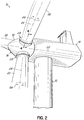
- the blades 20 are mounted to the hub 18 so as to be rotatable about a blade longitudinal axis 24 generally extending in the long direction of the blade (e.g., in a direction from the blade root to its tip), as illustrated by arrow 26 in Fig. 2 .
- the wind turbine 10 includes a blade bearing assembly, generally shown at 28, that facilitates the rotatable mounting of the blades 20 to the hub 18.
- the blade bearing assembly 28 is not of the roller element type, which is conventional, but is designed as a plain bearing. More particularly, in an exemplary embodiment, the blade bearing assembly 28 is characterized as a hydrostatic plain bearing.
- plain bearings have an increased operating life relative to roller element bearings.
- plain bearings do not have structural elements disposed between the two relative moving components for supporting the loads and facilitating low-friction movement. Instead, plain bearings generally have a fluid film disposed between the two relative moving components for supporting the loads and facilitating relative movement.
- plain bearings represent an attractive alternative to roller element bearings.
- plain bearings are designed to eliminate or minimize surface-to-surface contact and thus may operate with even lower friction, which may further increase efficiency.
- hydrostatic bearings there are two primary types of plain bearings: hydrostatic bearings and hydrodynamic bearings, each typically having an outer member defining an opening closely fitted around an inner member and a fluid film between the inner and outer members.
- hydrodynamic bearing the rotation of the inner member self-pressurizes the fluid film in a wedge between confronting surfaces of the members so as to support the load and maintain separation of the inner and outer members.
- the fluid film may not be able to fully support the load and maintain the inner and outer members separate from each other.
- the hydrodynamic bearing does not operate in a full-film condition, but instead operates in a boundary condition, wherein the load is partially carried by the fluid film and partially carried by direct surface contact with the outer member. Operating a hydrodynamic bearing in a boundary condition can cause wear or damage that may significantly shorten the operating life of the bearing.
- Hydrostatic bearings include an external pump that pressurizes the fluid film around the inner member (independent of the particular dynamics of the inner member) to support the load and maintain the inner member separate from the outer member, even when the inner member is rotating slowly or not at all relative to the outer member.
- hydrostatic bearings typically include a number of pockets or cavities typically formed in a confronting surface, which pockets are supplied with lubricating fluid (e.g., oil, grease, etc.) from an external reservoir and pressurized by an external pump.
- lubricating fluid e.g., oil, grease, etc.
- blade bearing assembly 28 may be configured as a hydrostatic plain bearing.
- Figs. 3 and 4 illustrate an exemplary embodiment of a blade bearing assembly 28 configured as a plain bearing, and more particularly, as a hydrostatic plain bearing.
- blade bearing assembly 28 includes an outer member 30 and an inner member 32 that is movable relative to the outer member 30.
- the inner member 32 is capable of rotating relative to the outer member 30 such as about axis 24.
- the outer member 30 is configured to be coupled to the rotor hub 18 and the inner member 32 is configured to be coupled to a blade 20 of the wind turbine 10.
- the outer member 30 may be coupled to the blade 20 and the inner member 32 may be coupled to the rotor hub 18 (not shown).
- the outer and inner members 30, 32 are separated by an externally pressurized fluid film ( Fig. 5 ).
- the inner member 32 may be configured as an annular ring (e.g., generally circular in plan view) that is, in one embodiment, substantially solid and generally rectangular in cross section.
- the invention is not so limited as the inner member 32 may alternatively be hollow and/or have other cross-sectional shapes.
- the inner member 32 generally includes an inner surface 34, an outer surface 36 generally opposed to inner surface 34, an upper surface 38 extending between inner and outer surfaces 34, 36, and a lower surface 40 also extending between inner and outer surfaces 34, 36, and generally opposed to upper surface 38.
- the inner surface 34 defines a central opening 42 in the inner member 32, as illustrated in the figures.
- the inner member 32 may be formed from any suitable material including various metals, such as steel.
- the inner member 32 is configured to be coupled to a wind turbine blade 20.
- the blade 20 has a generally cylindrical root end 44 that defines an end face 46 having a plurality of blind, threaded bores 48 formed therein.
- the inner member 32 also includes a plurality of throughbores 50 adjacent to, but slightly outward of inner surface 34 that generally align with the bores 48 in the root end 44 of blade 20 when the blade 20 is positioned adjacent the inner member 32.
- a fastener 52 such as a threaded bolt or the like, may be inserted into the throughbores 50 via, for example, the lower surface 40 in order to secure the blade 20 to the inner member 32.
- the cross dimension of central opening 42 may correspond to the cross dimension of an opening 54 defined in root end 44 such that the inner surface 34 of inner member 32 generally aligns with an inner surface 56 of the root end 44 of blade 20.
- the inner surface 34 may be inward of the inner surface 56 of the root end 44 (e.g., a smaller central opening 42 in inner member 32) or vice versa.
- the particular configuration shown in the figures is not limiting.
- the outer member 30 is also configured as an annular ring (e.g., generally circular in plan view), but which has a generally C-shaped cross-sectional profile that defines an annular cavity 58 configured to receive the inner member 32 therein ( Fig. 4 ).
- the outer member 30 includes an outer wall 60, an upper wall 62 coupled to an upper end of the outer wall 60, and a lower wall 64 coupled to a lower end of the outer wall 60 and generally opposed to upper wall 62.
- the outer member 30 includes no inner wall and is therefore open along an inner aspect thereof that provides access to the annular cavity 58 and provides the outer member 30 with its C-shaped profile.
- the outer wall 60 is generally circular in plan view and rectangular in cross section, and therefore generally includes an inner surface 66, an outer surface 68 generally opposed to inner surface 66, an upper surface 70 extending between inner and outer surfaces 66, 68, and a lower surface 72 also extending between inner and outer surfaces 66, 68 and generally opposed to upper surface 70.
- the upper wall 62 has a plate or disk-like configuration and includes an inner surface 74, an outer surface 76 generally opposed to inner surface 74, an upper surface 78 extending between inner and outer surfaces 74, 76, and a lower surface 80 also extending between inner and outer surfaces 74, 76 and generally opposed to upper surface 78.
- the lower wall 64 is similar to upper wall 62 and includes an inner surface 82, an outer surface 84 generally opposed to inner surface 82, an upper surface 86 extending between inner and outer surfaces 82, 84, and a lower surface 88 also extending between inner and outer surfaces 82, 84 and generally opposed to upper surface 86.
- the upper wall 62 may be coupled to the outer wall 60 adjacent the outer surface 76 thereof such that the outer surfaces 68, 76 are generally aligned and the upper wall 62 projects inwardly of the outer wall 60.
- the lower wall 64 may be coupled to the outer wall 60 adjacent the outer surface 84 thereof such that outer surfaces 68, 84 are generally aligned and the lower wall 64 projects inwardly of the outer wall 60. In this way, the upper wall 62, outer wall 60, and lower wall 64 define three bounding sides of the annular cavity 58.
- the upper and lower walls 62, 64 may include throughbores and the upper and lower surfaces 70, 72 of the outer wall 60 may include threaded bores for receiving threaded fasteners or the like that securely couple the walls together (not shown).
- Each of the outer wall 60, upper wall 62, and lower wall 64 may be formed of a suitable material, including, for example and without limitation, steel or other metals.
- the outer member 30 may be configured to be coupled to the hub 18 of wind turbine 10.
- the hub 18 includes an opening 90 and a plurality of throughbores 92 spaced about and adjacent to the opening 90.
- the outer member 30, and more particularly the lower wall 64 thereof also includes a plurality of blind, threaded bores 94 open to the lower surface 88 thereof that generally align with the throughbores 92 in the hub 18 when the outer member 30 is positioned adjacent the hub 18.
- a fastener 52 such as a threaded bolt or the like, may be inserted into the throughbores 92 via, for example, the interior of the hub 18 in order to secure the outer member 30 to the hub 18.
- the cross dimension of opening 90 may correspond to the cross dimension of an opening 96 defined by the inner surface 82 of the lower wall 64 such that the inner surface 82 of lower wall 64 generally aligns with an inner surface 98 that defines opening 90 in hub 18.
- Other arrangements are, however, possible and the inner surfaces 82, 98 do not have to be aligned with each other.
- the outer member 30 includes a plurality of pads, generally shown at 100, each capable of establishing and/or maintaining a fluid film 102 for supporting the inner member 32 within the outer member 30 in a substantially non-contact manner, but allowing relative movement therebetween ( Fig. 5 ).
- the lower surface 80 of the upper wall 62 includes at least one, and preferably a plurality of pads 100 coupled thereto and the upper surface 86 of the lower wall 64 also includes at least one, and preferably a plurality of pads 100 coupled thereto. As shown, there are six pads 100 on each of the lower surface 80 and the upper surface 86.
- pads 100 may be coupled to the lower and upper surfaces 80, 86 depending on the specific application. It should also be recognized that the lower and upper surfaces 80, 86 may have the same number of pads 100 or have a different number of pads 100 on each surface.
- the pads 100 may be coupled to inner member 32. More particularly, in such an alternative embodiment, pads 100 may be coupled to the upper and lower surfaces 38, 40 of the inner member 32. Additionally, while the figures illustrate separate pads 100 for establishing and/or maintaining fluid film 102, in yet another alternative embodiment, the pads 100 may be omitted and the fluid film 102 established directly between surfaces of the outer and inner members 30, 32.
- the fluid pockets or cavities may be formed directly in the lower surface 80 of the upper wall 62 and the upper surface 86 of the lower wall 64 (not shown). Alternatively, the fluid cavities may be formed directly in the upper and lower surfaces 38, 40 of the inner member 32 (not shown).
- a pad 100 has a generally arcuate shape and includes a generally arcuate inner surface 104, a generally arcuate outer surface 106, an engaging surface 108 configured to be coupled to the appropriate surface of the upper or lower walls 62, 64, a bearing surface 110 opposed to the engaging surface 108 and facing away from the surface to which the pad 100 is coupled and confronting the inner member 32, and a pair of spaced apart end surfaces 112, 114.
- the pads 100 may be coupled to the lower surface 80 of the upper wall 62 such that the inner surfaces 104 of the pads 100 are outward of the inner surface 74 of the upper wall 62, and the outer surfaces 106 are inward of the inner surface 66 of the outer wall 60.
- the pads 100 may be coupled to the upper surface 86 of the lower wall 64 such that the inner surfaces 104 of the pads 100 are outward of the inner surface 82 of the lower wall 64 and the outer surfaces 106 are inward of the inner surface 66 of the outer wall 60.
- a gap 116 may exist between adjacent pairs of pads 100, the size of which depends on the number and length of the pads 100 used in blade bearing assembly 28.
- Each of the pads 100 includes a fluid pocket or cavity 118 formed in the bearing surface 110 so as to confront or be open to the inner member 32.
- the fluid cavities 118 may be arranged so as to confront or be open to the outer member 30, and more particularly, the surfaces 80, 86 thereof (not shown).
- the cavity 118 may have various configurations including, for example and without limitation, a rectangular configuration, a curved or arcuate configuration, or a wedge configuration, each of which is described in more detail in co-owned U.S. Application Serial Nos. 12/883,695 and 12/883,702 .
- Each cavity 118 may have a depth, such as a maximum depth or an average depth, of about 2 mm.
- Each pad 100 includes at least one port 120 open to the cavity 118 in bearing surface 110.
- Port 120 operates as a high pressure port for introducing fluid to the blade bearing assembly 28 and pressurizing the fluid film 102 (exaggerated in the figures for illustrative purposes).
- the at least one fluid port 120 may be operatively coupled to a pressure generating device, such as a pump, schematically shown at 122, configured to pressurize the fluid film 102.
- the pump 122 should be rated so as to sufficiently pressurize the fluid film 102 to a level that supports the load on the inner member 32 in extreme scenarios, such as for example, a stand still condition or other high load dynamic conditions.
- the pump 122 may be operatively coupled to a fluid supply or reservoir 124 for providing a supply of the fluid that forms the fluid film 102 between the bearing surface 110 of the pads 100 and the inner member 32 during operation. As illustrated in Fig. 5 , the pump 122 may be operatively coupled to a controller, schematically shown at 126, for controlling the operation of the pump 122 and therefore pressurization of fluid film 102.
- the controller 126 may be an individual controller dedicated to controlling the pump 122. Alternatively, the controller 126 may be part of a larger control system for controlling the overall operation of the wind turbine 10.
- a valve shown schematically at 128, may be disposed in the line coupling the high pressure port 120 and the pump 122 so as to selectively isolate the fluid film 102 in the blade bearing assembly 28 from the pump 122.
- the valve 128 may be operatively coupled to the controller 126 for selectively opening and closing the valve 128. It should be recognized that each pad 100 may be operatively coupled to its own dedicated pump 122, reservoir 124, and valve 128. Alternatively, the pads 100 may collectively be operatively coupled to a single pump 122, reservoir 124, and valve 128.
- the port 120 in the pads 100 may also be open to the engaging surface 108 thereof, which is, in turn, in fluid communication with a flow channel 130 in the upper and lower walls 62, 64 of outer member 30. Additionally or alternatively, the port 120 may be open to the inner surface 104 of the pads 100 (shown in phantom in Fig. 4 ). Such an alternative port provides another option for accessing the pads 100 with a fluid supply conduit.
- the pads 100 may be formed of any suitable material including, for example and without limitation, a composite material, a metal, a plastic material, or a combination thereof.
- the pads 100 may be secured to the lower and upper surfaces 80, 86 of upper and lower walls 62, 64, respectively, using suitable fasteners such as threaded bolts or the like (not shown). As discussed in more detail below, however, other arrangements are possible.
- the assembled blade bearing assembly 28 in accordance with an exemplary embodiment is shown in Figs. 4 and 5 .
- the inner member 32 is positioned in the annular cavity 58 of outer member 30 such that the outer surface 36 of inner member 32 confronts the inner surface 66 of the outer wall 60; the upper surface 38 of the inner member 32 confronts the lower surface 80 of the upper wall 62; and the lower surface 40 of the inner member 32 confronts the upper surface 86 of the lower wall 64. More particularly, when assembled, the upper surface 38 of the inner member 32 confronts the bearing surface 110 of the pads 100 mounted on the lower surface 80 of the upper wall 62, and the lower surface 40 of the inner member 32 confronts the bearing surface 110 of the pads 100 mounted on the upper surface 86 of the lower wall 64.
- the pump 122 may be activated, such as by controller 126, so as to establish a pressurized fluid film 102 between the bearing surface 110 of the pads 100 on each side of the inner member 32 and the upper and lower surfaces 38, 40 of the inner member 32.
- the fluid film 102 is capable of supporting the load on the inner member 32 independent of the hydrodynamic forces, if any, developed in the fluid film 102. Consequently, surface-to-surface contact between the outer and inner members 30, 32 may be substantially avoided by fluid film 102.
- the loading of the inner member 32 is expected to be primarily in the axial or longitudinal direction (i.e., primarily directed along axis 24).
- the blade bearing assembly 28 is configured such that the pads 100 and the resulting fluid film 102 support the longitudinal loading of the inner member 32, such as by blade 20.
- the blade bearing assembly 28 may also be configured to accommodate some radial loading as well.
- the inner surface 66 of the outer wall 60 may include a radial bearing support shell 132 coupled thereto and configured to support the radial loading of the inner member 32.
- the support shell 132 may be configured as an annular band having an outer surface 134 thereof coupled to the inner surface 66 of the outer wall 60, such as with fasteners, bonding agents, etc., and an inner surface 136 configured to confront the outer surface 36 of the inner member 32.
- the support shell 132 is configured to be formed from a suitable low-friction material that not only provides support in a radial direction, but also provides for low-frictional rotation of the inner member 32 within the outer member 30.
- the support shell 132 may be formed from polytetrafluoroethylene (PTFE) or other suitable, low-friction materials capable of withstanding the expected radial loads imposed thereon.
- PTFE polytetrafluoroethylene
- the wind turbine 10 may include a blade pitch system, schematically shown in phantom at 138 in Fig.
- the inner surface 34 of the inner member 32 may be configured to cooperate with a pitch mechanism for rotating the inner member 32 relative to the outer member 30. More particularly, the inner surface 34 of the inner member 32 may include a rib 140 having a plurality of teeth 142 configured to mate with a toothed gear 144 operatively coupled to a pitch control motor 146.
- the pitch control motor 146 may be coupled to a controller, such as controller 126 or a wind turbine controller (discussed in more detail below), for controlling the pitch of the blades 20.
- the pitch system 138 may include a plurality of pitch motors 146 operatively coupled to toothed rib 140 for pitching blades 20 and is not limited to the particular configuration shown herein.
- the pads 100 may be fixedly secured to the surfaces 80, 86 of the outer member 30, such as with a threaded fastener or the like (not shown). As such, the pads 100 may not be movable relative to the supporting surfaces 80, 86 of the outer member 30.
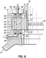
- Fig. 6 in which like reference numerals refer to like features in Fig. 5 , illustrates an alternative embodiment wherein the pads 100 are movably coupled to surfaces 80, 86 of the outer member 30. More particularly, the pads 100 may be mounted to surfaces 80, 86 of outer member 30 so as to be biased toward the inner member 32.
- the biasing force may be provided by one or more springs 148 on each of the pads 100 for coupling the pads 100 to surfaces 80, 86 of the outer member 30.
- Other biasing mechanisms including, for example, pneumatic or hydraulic actuators, may also be possible for generating a biasing force on the pads 100 toward the inner member 32.
- Such a biasing force on the pads 100 maintains the bearing surface 110 of the pads 100 in close proximity to the confronting surfaces 38, 40 of the inner member 32 so that the fluid film 102 is not disrupted during operation (e.g., maintain the pressure within fluid film 102).
- the movable coupling of the pads 100 to the outer member 30 provides a self-alignment feature to the blade bearing assembly 28.
- the ability of the pads 100 to move slightly would, in turn, allow the blade bearing assembly 28 to more readily accommodate the misalignment. This aspect allows the blade bearing assembly 28 to be more robust in its implementation.
- components of the blade bearing assembly 28 may be configured to be replaceable in a relatively quick and convenient manner.
- the replacement of conventional roller element blade bearing assemblies often requires that the blade 20 be completely removed from the hub 18. This then requires a crane and other heavy-duty equipment to effectuate the blade bearing replacement.
- the replacement of conventional blade bearings is often time consuming, labor intensive, and expensive.
- the pads 100 are configured to be replaceable without removal of the blade 20 from the hub 18.
- the pads 100 on the lower wall 64 may be accessible from inside the hub 18.
- a plurality of access openings 150 may be formed in the outer wall 60 of outer member 30.
- the access openings 150 may be covered by a removable door or hatch, a slidable door, or other removable covering that provides selective access to the annular cavity 58 such that the pads 100 on the upper wall 62 may be replaced.
- the support shell 132 may be replaceable via, for example, the access openings 150 in the outer wall 60.
- the wind turbine 10 may include a control system having a wind turbine controller, schematically shown at 152, operatively coupled to the blade bearing assembly 28 for controlling operation of the wind turbine 10 based on certain conditions in the blade bearing assembly 28.
- the controller 152 may be configured to change the dynamic state of the wind turbine 10 or additionally or alternatively modify a feature or characteristic of the blade bearing assembly 28 itself so as to reduce the likelihood of damage to the blade bearing assembly 28. In this way, the operating life of the blade bearing assembly 28 may be extended.
- the wind turbine controller 152 may be operatively coupled to one or more sub-systems (having controllers which may be separate or integrated within controller 152) effective to alter the dynamic state of the wind turbine 10.
- the controller 152 may be operatively coupled to: i) a yaw controller (not shown) for controlling the yaw of the rotor 16 about tower 12; ii) a pitch controller (not shown) for controlling the pitch of the blades 20 relative to the wind direction; and/or iii) a brake system (not shown) for resisting the rotation of the rotor 16 about the longitudinal axis 22.
- these sub-systems have the ability to affect the loading on the blades 20, which, in turn, affects operation of the blade bearing assembly 28.
- the sub-systems provided above are exemplary and those of ordinary skill in the art may recognize other sub-systems that affect the dynamic state of the wind turbine 10.
- the wind turbine controller 152 may be further operatively coupled to the blade bearing assembly 28 and capable of affecting the state of the blade bearing assembly 28 so as to better accommodate the loads on the blades 20.
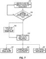
- the controller 152 may monitor one or more parameters associated with operation of the blade bearing assembly 28, as in step 154.
- the monitored parameter(s) is generally indicative of the loads applied to the blades; several examples of which are described in greater detail below.
- the monitored parameter(s) is then compared to a threshold value(s) stored in controller 152, as in step 156. If the monitored parameter(s) is less than the threshold value(s) then the wind turbine 10 continues to operate without intervention from this particular control system.
- the controller 152 is configured to alter the operation of the wind turbine 10 so as to reduce the load on the blades 20, and/or change the operating condition of blade bearing assembly 28 so as to more readily accommodate the load on the blades 20.
- the controller 152 may be configured to alter the dynamic state of the wind turbine 10 to reduce the load on the blade, as indicated at 158.
- the controller 152 may be configured to yaw the rotor 16 relative to the tower 12 so as to turn the rotor 16 out of the wind, as indicated at 160.
- the controller 152 may be configured to pitch the rotor blades 20 out of the wind so as to reduce the driving force of the rotor 16, and thus the loading of the blades 20, as at 162.
- the controller 152 may be configured to apply a brake and thereby slow the angular velocity of the rotor 16, as at 164.
- altering the dynamic state of the wind turbine 10 in such a manner is configured to prevent or reduce the likelihood of damaging the blade bearing assembly 28 and shortening its operating life.
- the controller 152 may be configured to increase the pressurization of the fluid film 102 between the outer and inner members 30, 32 of blade bearing assembly 28, as indicated at step 166, so that the blade bearing assembly 28 may better accommodate the load on the blades 20. This may be achieved, for example, by increasing the output of the pump 122. Similar to the above, altering the pressurization of the fluid film 102 in the blade bearing assembly 28 is configured to prevent or reduce the likelihood of damaging the blade bearing assembly 28 and shortening its operating life.
- various techniques may be implemented wherein one or more properties of the fluid film 102 may be monitored to provide an indication of the load on the blades 20.
- one or more sensors schematically illustrated at 168 ( Fig. 5 ), may be in communication with the fluid film 102 between the pads 100 and the inner member 32 for monitoring at least one property of the fluid film 102.
- the sensors 168 may further be operatively coupled to controller 152 for affecting the operation of the wind turbine 10 in the event a potentially damaging or undesirable condition may exist in the blade bearing assembly 28.
- the property of the fluid film 102 being monitored by sensors 168 is the pressure.
- the sensors 168 may be pressure transducers capable of measuring the pressure of the fluid film 102 at certain locations, which may be selected by locating one or more suitable ports in the pads 100 and/or the inner member 32.
- Such pressure transducers are generally known in the art and are commercially available. Thus, a detailed description of the pressure transducers is considered unnecessary.
- the pressure transducers are operatively coupled to the controller 152 and are configured to send a pressure signal indicative of the load on the blades 20. If the pressure, as indicated by the pressure transducer, exceeds a threshold value, then operation of the wind turbine 10 may be altered by changing the dynamic state of the wind turbine 10 or by pressurization of the fluid film 102, as was more fully explained above.
- the property of the fluid film 102 being monitored by sensors 168 is the temperature.
- the sensors 168 may be temperature sensors capable of measuring the temperature of the fluid film 102 at certain locations, which may be selected by locating one or more suitable ports in the pads 100 and/or the inner member 32. Such temperature sensors are generally known in the art and are commercially available. Thus, a detailed description of the temperature sensors is considered unnecessary.
- the temperature sensors are operatively coupled to the controller 152 and are configured to send a temperature signal indicative of the load on the blades 20. If the temperature, as indicated by the temperature sensors, exceeds a threshold value, then operation of the wind turbine 10 may be altered by changing the dynamic state of the wind turbine 10 or by pressurization of the fluid film 102, as explained above.
- the property of the fluid film 102 being monitored by sensors 168 is the film thickness.
- the sensors 168 may be film thickness sensors or proximity sensors capable of measuring or indicating the thickness of the fluid film 102 at certain locations.
- the film thickness sensors may operate on an inductive or capacitive theory (e.g., proximity sensors). Such sensors are generally known in the art and are commercially available. Thus, a detailed description of the types of sensors is considered unnecessary. Other sensors operating on a host of other principles or theories may also be used.
- the proximity sensors are operatively coupled to the controller 152 and are configured to send a distance signal indicative of the load on the blades 20.
- operation of the wind turbine 10 may be altered by changing the dynamic state of the wind turbine 10 or by increased pressurization of the fluid film 102, as was more fully explained above.
Claims (14)
- Éolienne (10) comprenant :une tour (12) ;une nacelle (14) située de manière adjacente à un dessus de la tour ;un rotor (16) présentant un moyeu (18) et une pluralité de pales (20) s'étendant depuis celui-ci et configuré pour interagir avec le vent afin de faire tourner le rotor ;un ensemble palier de pale (28) pour le montage rotatif des pales sur le moyeu ; etun système de calage pour la rotation d'une pale par rapport au moyeu,dans laquelle l'ensemble palier de pale comprend un ensemble palier lisse comprenant :un élément extérieur (30) monté sur un de la pale ou du moyeu de l'éolienne et incluant une cavité annulaire (58) ;un élément intérieur (32) monté sur l'autre de la pale ou du moyeu de l'éolienne et positionné dans la cavité annulaire (58) de sorte que les éléments intérieur et extérieur soient mobiles l'un par rapport à l'autre ;une pluralité de cavités fluidiques (118) associées avec un de l'élément extérieur ou intérieur, les cavités faisant face à l'autre de l'élément extérieur ou intérieur,dans laquelle les cavités fluidiques sont configurées pour être couplées en fonctionnement à une alimentation en fluide et une source de pression pour établir un film de fluide pressurisé (102) entre les éléments intérieur et extérieur, le film de fluide étant configuré pour supporter le chargement des pales de sorte à maintenir la séparation des éléments intérieur et extérieur mais toujours permettre le mouvement relatif entre eux.
- Éolienne (10) selon la revendication 1, comprenant en outre une pluralité de patins (100) couplés à un de l'élément extérieur ou intérieur, les cavités de fluide étant définies dans une surface des patins qui fait face à l'autre de l'élément extérieur ou intérieur.
- Éolienne (10) selon la revendication 2, dans laquelle les patins sont généralement de forme arquée.
- Éolienne (10) selon la revendication 2 ou 3, dans laquelle les patins sont couplés de manière mobile à un de l'élément extérieur ou intérieur.
- Éolienne (10) selon la revendication 4, dans laquelle les patins sont couplés à un de l'élément extérieur ou intérieur par au moins un ressort, le ressort sollicitant les patins vers l'autre de l'élément extérieur ou intérieur.
- Éolienne (10) selon l'une quelconque des revendications 1 à 5, comprenant en outre une coque de support (132) disposée entre l'élément intérieur et extérieur et configurée pour supporter au moins un chargement partiel de l'ensemble palier de pale.
- Éolienne (10) selon l'une quelconque des revendications 1 à 6, dans laquelle l'élément intérieur est formé comme une bague annulaire présentant une surface intérieure (34, 66), une surface extérieure (36, 68), une surface supérieure (38, 70) et une surface inférieure (40, 72), et l'élément extérieur est formé comme une bague annulaire présentant une paroi extérieure (60), une paroi supérieure (62) couplée à la paroi extérieure, et une paroi inférieure (64) couplée à la paroi extérieure, les parois extérieure, supérieure et inférieure formant des limites de la cavité annulaire (58).
- Éolienne (10) selon la revendication 7, dans laquelle la surface intérieure de l'élément intérieur inclut une pluralité de dents (142) configurées pour coopérer avec un mécanisme de calage pour déplacer un de l'élément extérieur ou intérieur par rapport à l'autre de l'élément extérieur ou intérieur.
- Éolienne (10) selon la revendication 7 ou 8, dans laquelle au moins un patin (100) est couplé à une surface inférieure de la paroi supérieure (62) et au moins un patin est couplé à une surface supérieure de la paroi inférieure (64).
- Éolienne selon l'une quelconque des revendications précédentes, comprenant en outre une pompe (122) pour la pressurisation du film de fluide entre les éléments extérieur et intérieur de l'ensemble palier de pale.
- Procédé de fonctionnement d'une éolienne (10) selon l'une quelconque des revendications 1 à 9; ledit ensemble palier de pale(28) incluant un élément extérieur (30) couplé à un de la pale de rotor ou du moyeu, un élément intérieur (32) étant couplé à l'autre de la pale de rotor (20) ou du moyeu (18), et un film de fluide (102) séparant les éléments extérieur et intérieur, l'éolienne présentant aussi au moins un sous-système capable de modifier un état dynamique de l'éolienne, comprenant :la surveillance d'au moins un paramètre du film de fluide indiquant une charge sur la pale ;la comparaison de l'au moins un paramètre avec un critère seuil ; etla réalisation d'au moins une des étapes suivantes lorsque l'au moins un paramètre satisfait au critère seuil : i) la modification de l'état dynamique de l'éolienne pour réduire la charge sur la pale ; et ii) la modification de l'état de l'ensemble palier de pale de sorte à mieux loger la charge sur la pale.
- Procédé selon la revendication 11, dans lequel la surveillance d'au moins un paramètre du film de fluide comprend au moins une de la surveillance d'une pression du film de fluide, la surveillance d'une température du film de fluide, et la surveillance d'une épaisseur du film de fluide.
- Procédé selon la revendication 11 ou 12, dans lequel la modification de l'état dynamique de l'éolienne pour réduire la charge sur la pale comprend en outre au moins un de : i) l'orientation de la nacelle par rapport à la tour; ii) le calage des pales de l'éolienne ; et iii) l'application d'un frein pour ralentir la vitesse du rotor.
- Procédé selon l'une quelconque des revendications 11 à 13, dans lequel la modification de l'état de l'ensemble palier de sorte à mieux loger la charge sur la pale comprend en outre l'augmentation de la pression dans le film de fluide.
Applications Claiming Priority (1)
| Application Number | Priority Date | Filing Date | Title |
|---|---|---|---|
| US12/987,596 US8172531B2 (en) | 2011-01-10 | 2011-01-10 | Plain bearing for a wind turbine blade and method of operating a wind turbine having such a plain bearing |
Publications (3)
| Publication Number | Publication Date |
|---|---|
| EP2474733A2 EP2474733A2 (fr) | 2012-07-11 |
| EP2474733A3 EP2474733A3 (fr) | 2015-10-07 |
| EP2474733B1 true EP2474733B1 (fr) | 2019-10-23 |
Family
ID=44341842
Family Applications (1)
| Application Number | Title | Priority Date | Filing Date |
|---|---|---|---|
| EP12150475.7A Active EP2474733B1 (fr) | 2011-01-10 | 2012-01-09 | Pale d'éolienne avec palier lisse et procédé de fonctionnement de l'éolienne |
Country Status (3)
| Country | Link |
|---|---|
| US (1) | US8172531B2 (fr) |
| EP (1) | EP2474733B1 (fr) |
| CN (1) | CN102588219B (fr) |
Families Citing this family (37)
| Publication number | Priority date | Publication date | Assignee | Title |
|---|---|---|---|---|
| CN102292562A (zh) * | 2008-12-04 | 2011-12-21 | 约亨·科茨 | 复合钢轴承及制造方法 |
| US8882355B2 (en) * | 2008-12-15 | 2014-11-11 | Jochen Corts | Segmented composite bearings and wind generator utilizing hydraulic pump/motor combination |
| AT509624B1 (de) * | 2010-04-14 | 2012-04-15 | Miba Gleitlager Gmbh | Windkraftanlage |
| AT509625B1 (de) * | 2010-04-14 | 2012-02-15 | Miba Gleitlager Gmbh | Lagerelement |
| EP2511521B2 (fr) | 2011-04-14 | 2021-06-16 | Siemens Gamesa Renewable Energy A/S | Articulation de pas |
| DK2562081T3 (en) * | 2011-08-25 | 2015-07-20 | Imo Holding Gmbh | Hub for wind power plants and the device for adjusting the number of elements in relation to each other |
| EP2568167A1 (fr) * | 2011-09-08 | 2013-03-13 | Siemens Aktiengesellschaft | Éolienne à commande directe |
| EP2568163A1 (fr) * | 2011-09-08 | 2013-03-13 | Siemens Aktiengesellschaft | Éolienne à commande directe |
| EP2573391B1 (fr) * | 2011-09-22 | 2018-11-21 | Moventas Gears Oy | Procédé et agencement pour contrôler la lubrification d'un système d'engrenage |
| US20120134808A1 (en) * | 2011-12-06 | 2012-05-31 | Mikael Lindberg | Wind turbine oil lubrication pump |
| EP2626577B1 (fr) * | 2012-02-10 | 2018-11-14 | Siemens Aktiengesellschaft | Procédé de commande d'éolienne et agencement d'éolienne |
| EP2703644B1 (fr) * | 2012-08-27 | 2016-08-03 | Alstom Wind, S.L.U. | Système de positionnement angulaire d'une éolienne |
| EP2711568B1 (fr) * | 2012-09-24 | 2018-05-30 | Siemens Aktiengesellschaft | Palier coulissant et procédé pour effectuer de la maintenance au niveau du palier coulissant |
| EP2711569B1 (fr) * | 2012-09-24 | 2014-12-17 | Siemens Aktiengesellschaft | Palier coulissant et procédé pour effectuer un service au niveau d'un palier coulissant |
| DE102013203263A1 (de) * | 2013-02-27 | 2014-08-28 | Skf Lubrication Systems Germany Ag | Vorrichtung zur Schmierstoffzufuhr zu einer Schmierstelle in einer Maschine |
| DE102013211710C5 (de) * | 2013-06-20 | 2016-11-10 | Siemens Aktiengesellschaft | Windkraftanlage mit einem Gleitlager |
| JP6282203B2 (ja) * | 2014-09-12 | 2018-02-21 | 株式会社日立製作所 | 風力発電装置及び軸流タイプブレード |
| CN107208605A (zh) * | 2014-10-30 | 2017-09-26 | 李智贤 | 手动型叶片节距控制模块 |
| US9951818B2 (en) | 2015-05-13 | 2018-04-24 | Wind Solutions, LLC. | Wind turbine yaw bearing pre-load |
| CN105257587A (zh) * | 2015-11-02 | 2016-01-20 | 苏州市淞舜五金有限公司 | 一种平稳减震轴承 |
| TWI597436B (zh) | 2016-03-15 | 2017-09-01 | 財團法人工業技術研究院 | 液靜壓軸承 |
| DE102016210039A1 (de) * | 2016-06-07 | 2017-12-07 | Wobben Properties Gmbh | Windenergieanlagen-Drehverbindung, Rotorblatt und Windenergieanlage mit selbiger |
| WO2018026756A1 (fr) | 2016-08-02 | 2018-02-08 | Saint-Gobain Performance Plastics Corporation | Palier |
| US10781796B2 (en) * | 2017-07-11 | 2020-09-22 | General Electric Company | Clamping apparatus for positioning a main bearing of a wind turbine during an installation and/or repair procedure |
| US10935003B2 (en) * | 2017-11-01 | 2021-03-02 | General Electric Company | Lubrication system for a main bearing of a wind turbine |
| CN111417778B (zh) * | 2017-11-16 | 2022-12-16 | 乌本产权有限公司 | 风能设备的转子叶片与转子毂的连接 |
| DE102017223386A1 (de) | 2017-12-20 | 2019-06-27 | Zf Friedrichshafen Ag | Gleitlageranordnung für eine schwere Welle, insbesondere einer Windkraftanlage, sowie Steuersystem und Verfahren zur Schmierölversorgung derselben |
| DE102017223418B4 (de) | 2017-12-20 | 2023-05-25 | Zf Friedrichshafen Ag | Modellbasiertes Verfahren und System zur Zustandsüberwachung eines Gleitlagers, insbesondere für Windkraftanlagen |
| US11060503B2 (en) * | 2018-03-13 | 2021-07-13 | Wind Solutions, Llc | Yaw pad engagement features |
| TWI696767B (zh) * | 2018-11-29 | 2020-06-21 | 財團法人工業技術研究院 | 液靜壓軸承總成 |
| CN110360066B (zh) * | 2019-07-11 | 2021-03-26 | 上海电气风电集团股份有限公司 | 滑动主轴承传动链及包括其的风力涡轮机 |
| CN110345154B (zh) * | 2019-07-15 | 2022-11-11 | 北京金风科创风电设备有限公司 | 变桨滑动轴承、风力发电机组的变桨系统及风力发电机组 |
| EP3767118B1 (fr) * | 2019-07-19 | 2022-11-23 | Siemens Gamesa Renewable Energy A/S | Palier de pas de pale de rotor d'éolienne |
| CN112555275B (zh) * | 2019-09-26 | 2023-06-02 | 北京金风科创风电设备有限公司 | 轴承和风力发电机组 |
| CN112727716A (zh) * | 2019-10-14 | 2021-04-30 | 新疆金风科技股份有限公司 | 变桨滑动轴承、变桨装置及风力发电机组 |
| EP3904712A1 (fr) * | 2020-04-28 | 2021-11-03 | Siemens Gamesa Renewable Energy A/S | Palier principal d'éolienne |
| CN111963374B (zh) * | 2020-08-19 | 2021-10-22 | 中国船舶重工集团海装风电股份有限公司 | 一种风力发电机组的变桨系统装置 |
Citations (1)
| Publication number | Priority date | Publication date | Assignee | Title |
|---|---|---|---|---|
| EP2616678B1 (fr) * | 2010-09-16 | 2015-01-21 | Vestas Wind Systems A/S | Système de commande pour éolienne et procédé d'exploitation d'une éolienne basée sur la surveillance d'un palier |
Family Cites Families (37)
| Publication number | Priority date | Publication date | Assignee | Title |
|---|---|---|---|---|
| US3387899A (en) * | 1966-08-17 | 1968-06-11 | Heald Machine Co | Bearing |
| US3708215A (en) * | 1968-11-14 | 1973-01-02 | Mechanical Tech Inc | Hybrid boost bearing assembly |
| US3680932A (en) * | 1970-09-10 | 1972-08-01 | Westinghouse Electric Corp | Stable journal bearing |
| GB1448120A (en) | 1973-10-08 | 1976-09-02 | Ind Eng Ltd | Plate bending machines |
| US4029434A (en) * | 1975-05-22 | 1977-06-14 | Kenney Clarence E | Variable pitch mounting for airfoil blades of a windmill or propeller |
| DE2550791A1 (de) * | 1975-11-12 | 1977-05-18 | Kugelfischer G Schaefer & Co | Grossgleitlager, insbesondere gelenklager |
| CA1096431A (fr) * | 1978-07-03 | 1981-02-24 | Kunio Shibata | Coussinet hydraulique |
| IT8018706A0 (it) | 1980-04-14 | 1980-04-14 | Bonaccorso Francesco | Cuscinetto portante a sostentamento fluido-statico e fluido-dinamico costruibile in serie |
| DE3332357C1 (de) * | 1983-09-08 | 1985-04-04 | Klein, Schanzlin & Becker Ag, 6710 Frankenthal | Hydrostatisch-hydrodynamisches Hybrid-Mehrgleitflaechenradiallager |
| SU1320550A1 (ru) | 1985-10-08 | 1987-06-30 | Краматорский Научно-Исследовательский И Проектно-Технологический Институт Машиностроения | Способ регулировани работы гибридной опоры скольжени |
| GB9223721D0 (en) | 1992-11-12 | 1992-12-23 | Neale Michael J | A spherical plain bearing with pads |
| CN2157133Y (zh) * | 1993-04-12 | 1994-02-23 | 储大伟 | 砂金船过桥托辊 |
| GB2292192B (en) * | 1994-08-06 | 1997-12-10 | Glacier Metal Co Ltd | Journal bearings |
| DE19629168C1 (de) * | 1996-07-19 | 1997-10-30 | Voith Turbo Kg | Windturbine mit einem Turm, einer Gondel und einer Bremse zum Arretieren der Schwenkbewegung der Gondel |
| US6050727A (en) * | 1997-04-09 | 2000-04-18 | Pioneer Motor Bearing Company | Hydrostatically supported tilting pad journal bearing improvements |
| GB9818098D0 (en) * | 1998-08-19 | 1998-10-14 | Corac Group Plc | Improvements in or relating to bearings |
| US6186061B1 (en) * | 1999-05-11 | 2001-02-13 | The Minster Machine Company | Press bearing lubrication system |
| DE19962978C1 (de) * | 1999-12-24 | 2001-08-30 | Aloys Wobben | Windenergieanlage mit einem turmgestützten Maschinenkopf |
| DE10043593B4 (de) * | 2000-09-01 | 2014-01-09 | Renk Ag | Getriebe für Windgeneratoren |
| DE10043936C2 (de) * | 2000-09-07 | 2003-09-04 | Skf Gmbh | Gleitlager |
| US6739756B2 (en) * | 2001-03-12 | 2004-05-25 | Whm Holding Corporation | Combination thrust bearing and journal bearing, and method for distributing fluid to same |
| DE10223125A1 (de) | 2002-05-24 | 2004-03-25 | Ab Skf | Gleitlager für eine Windenergieanlage |
| DE20208133U1 (de) | 2002-05-24 | 2003-10-02 | Skf Ab | Gleitlager zur axialen und radialen Lagerung |
| DE10255745A1 (de) | 2002-11-28 | 2004-06-17 | Jörck, Hartmut | Direkt angetriebene Windenergieanlage mit im Generator integriertem Lager |
| DE10357026B3 (de) | 2003-12-03 | 2005-06-09 | Repower Systems Ag | Windenergieanlage |
| DE10360693A1 (de) | 2003-12-19 | 2005-07-14 | Winergy Ag | Planetengetriebe, insbesondere für Windkraftanlagen |
| CN100567749C (zh) | 2006-07-31 | 2009-12-09 | 大连三环复合材料技术开发有限公司 | 风力发电机组主轴调心滑动轴承 |
| DE102006051817A1 (de) | 2006-11-03 | 2008-05-08 | Schaeffler Kg | Lageranordnung zur drehbaren Lagerung eines Planetenrades auf einem Planetenträger |
| DE102007008758A1 (de) * | 2007-02-22 | 2008-08-28 | Schuler Pressen Gmbh & Co. Kg | Getriebe-Nabeneinheit für eine Windkraftanlage |
| DE102007012408A1 (de) | 2007-03-15 | 2008-09-18 | Aerodyn Engineering Gmbh | Windenergieanlagen mit lastübertragenden Bauteilen |
| WO2009035548A1 (fr) * | 2007-09-13 | 2009-03-19 | Elka Precision, Llc | Palier lisse hybride hydrostatique (pneumatique) à multiples évidements |
| DK2101071T3 (da) * | 2008-03-12 | 2012-01-09 | Siemens Ag | Indretning omfattende en støttestruktur og en roterende aksel og vindmølle |
| GB0817617D0 (en) | 2008-09-25 | 2008-11-05 | Ricardo Uk Ltd | Bearing for wind turbine |
| US20100129223A1 (en) | 2008-11-21 | 2010-05-27 | Pedro Luis Benito Santiago | Bearing device and wind turbine having said bearing device |
| CN201292917Y (zh) * | 2008-11-24 | 2009-08-19 | 陈向阳 | 风力发电机 |
| US9297363B2 (en) | 2009-07-10 | 2016-03-29 | Siemens Aktiengesellschaft | Wind turbine main bearing |
| US8079761B1 (en) * | 2010-09-16 | 2011-12-20 | Vestas Wind Systems A/S | Cylindrical plain bearing pocket arrangement and wind turbine having such a cylindrical plain bearing |
-
2011
- 2011-01-10 US US12/987,596 patent/US8172531B2/en not_active Expired - Fee Related
- 2011-12-28 CN CN201110448096.4A patent/CN102588219B/zh not_active Expired - Fee Related
-
2012
- 2012-01-09 EP EP12150475.7A patent/EP2474733B1/fr active Active
Patent Citations (1)
| Publication number | Priority date | Publication date | Assignee | Title |
|---|---|---|---|---|
| EP2616678B1 (fr) * | 2010-09-16 | 2015-01-21 | Vestas Wind Systems A/S | Système de commande pour éolienne et procédé d'exploitation d'une éolienne basée sur la surveillance d'un palier |
Also Published As
| Publication number | Publication date |
|---|---|
| US20110188988A1 (en) | 2011-08-04 |
| US8172531B2 (en) | 2012-05-08 |
| CN102588219B (zh) | 2014-10-29 |
| EP2474733A2 (fr) | 2012-07-11 |
| CN102588219A (zh) | 2012-07-18 |
| EP2474733A3 (fr) | 2015-10-07 |
Similar Documents
| Publication | Publication Date | Title |
|---|---|---|
| EP2474733B1 (fr) | Pale d'éolienne avec palier lisse et procédé de fonctionnement de l'éolienne | |
| US8734105B2 (en) | Control system for a wind turbine and method of operating a wind turbine based on monitoring a bearing | |
| US8075190B1 (en) | Spherical plain bearing pocket arrangement and wind turbine having such a spherical plain bearing | |
| US8727728B2 (en) | Convertible bearing for a wind turbine and method for operating same | |
| EP3252306B1 (fr) | Éolienne comprenant un palier lisse | |
| JP5650210B2 (ja) | 風力タービン主軸受け | |
| EP3460238B1 (fr) | Éolienne | |
| EP2694810B2 (fr) | Éolienne à entraînement direct | |
| EP2636890B1 (fr) | Agencement pour ajuster l'angle d'incidence de pale de rotor | |
| KR101882601B1 (ko) | 하이브리드 샤프트 베어링, 하이브리드 샤프트 베어링을 포함하는 풍력 발전기, 하이브리드 샤프트 베어링의 사용 및 하이브리드 샤프트 베어링 작동 방법 | |
| EP2199598B1 (fr) | Turbine hydroélectrique avec un frein passif et procédé d'opération | |
| EP2306002B1 (fr) | Des systèmes et des méthodes pour assembler un système de réglage de pas pour une éolienne | |
| EP2697505B1 (fr) | Éolienne à commande directe | |
| US9528500B2 (en) | System for lubricating gears in a wind turbine | |
| US10385830B2 (en) | Compound main bearing arrangement for a wind turbine | |
| CN101892955A (zh) | 修复变桨控制部件的方法和系统 | |
| US20120134808A1 (en) | Wind turbine oil lubrication pump | |
| EP3112669B1 (fr) | Arrangement de palier pour la pale d'une éolienne | |
| CN211144709U (zh) | 一种用于垂直轴风力发电机组的中心支承连接箱 | |
| EP4108944B1 (fr) | Assemblage de palier d'orientation | |
| Kyling et al. | The Drivetrain |
Legal Events
| Date | Code | Title | Description |
|---|---|---|---|
| PUAI | Public reference made under article 153(3) epc to a published international application that has entered the european phase |
Free format text: ORIGINAL CODE: 0009012 |
|
| AK | Designated contracting states |
Kind code of ref document: A2 Designated state(s): AL AT BE BG CH CY CZ DE DK EE ES FI FR GB GR HR HU IE IS IT LI LT LU LV MC MK MT NL NO PL PT RO RS SE SI SK SM TR |
|
| AX | Request for extension of the european patent |
Extension state: BA ME |
|
| RAP1 | Party data changed (applicant data changed or rights of an application transferred) |
Owner name: VESTAS WIND SYSTEMS A/S |
|
| PUAL | Search report despatched |
Free format text: ORIGINAL CODE: 0009013 |
|
| AK | Designated contracting states |
Kind code of ref document: A3 Designated state(s): AL AT BE BG CH CY CZ DE DK EE ES FI FR GB GR HR HU IE IS IT LI LT LU LV MC MK MT NL NO PL PT RO RS SE SI SK SM TR |
|
| AX | Request for extension of the european patent |
Extension state: BA ME |
|
| RIC1 | Information provided on ipc code assigned before grant |
Ipc: F16C 32/06 20060101ALI20150902BHEP Ipc: F03D 1/06 20060101AFI20150902BHEP Ipc: F03D 11/00 20060101ALI20150902BHEP |
|
| 17P | Request for examination filed |
Effective date: 20160407 |
|
| RBV | Designated contracting states (corrected) |
Designated state(s): AL AT BE BG CH CY CZ DE DK EE ES FI FR GB GR HR HU IE IS IT LI LT LU LV MC MK MT NL NO PL PT RO RS SE SI SK SM TR |
|
| STAA | Information on the status of an ep patent application or granted ep patent |
Free format text: STATUS: EXAMINATION IS IN PROGRESS |
|
| 17Q | First examination report despatched |
Effective date: 20180502 |
|
| REG | Reference to a national code |
Ref country code: DE Ref legal event code: R079 Ref document number: 602012065006 Country of ref document: DE Free format text: PREVIOUS MAIN CLASS: F03D0001060000 Ipc: F03D0080700000 |
|
| GRAP | Despatch of communication of intention to grant a patent |
Free format text: ORIGINAL CODE: EPIDOSNIGR1 |
|
| STAA | Information on the status of an ep patent application or granted ep patent |
Free format text: STATUS: GRANT OF PATENT IS INTENDED |
|
| RIC1 | Information provided on ipc code assigned before grant |
Ipc: F03D 17/00 20160101ALI20190430BHEP Ipc: F16C 32/06 20060101ALI20190430BHEP Ipc: F03D 80/70 20160101AFI20190430BHEP Ipc: F03D 1/06 20060101ALI20190430BHEP |
|
| INTG | Intention to grant announced |
Effective date: 20190523 |
|
| GRAS | Grant fee paid |
Free format text: ORIGINAL CODE: EPIDOSNIGR3 |
|
| GRAA | (expected) grant |
Free format text: ORIGINAL CODE: 0009210 |
|
| STAA | Information on the status of an ep patent application or granted ep patent |
Free format text: STATUS: THE PATENT HAS BEEN GRANTED |
|
| AK | Designated contracting states |
Kind code of ref document: B1 Designated state(s): AL AT BE BG CH CY CZ DE DK EE ES FI FR GB GR HR HU IE IS IT LI LT LU LV MC MK MT NL NO PL PT RO RS SE SI SK SM TR |
|
| REG | Reference to a national code |
Ref country code: GB Ref legal event code: FG4D |
|
| REG | Reference to a national code |
Ref country code: CH Ref legal event code: EP |
|
| REG | Reference to a national code |
Ref country code: IE Ref legal event code: FG4D |
|
| REG | Reference to a national code |
Ref country code: DE Ref legal event code: R096 Ref document number: 602012065006 Country of ref document: DE |
|
| REG | Reference to a national code |
Ref country code: AT Ref legal event code: REF Ref document number: 1193923 Country of ref document: AT Kind code of ref document: T Effective date: 20191115 |
|
| REG | Reference to a national code |
Ref country code: NL Ref legal event code: MP Effective date: 20191023 |
|
| REG | Reference to a national code |
Ref country code: LT Ref legal event code: MG4D |
|
| PG25 | Lapsed in a contracting state [announced via postgrant information from national office to epo] |
Ref country code: LT Free format text: LAPSE BECAUSE OF FAILURE TO SUBMIT A TRANSLATION OF THE DESCRIPTION OR TO PAY THE FEE WITHIN THE PRESCRIBED TIME-LIMIT Effective date: 20191023 Ref country code: PL Free format text: LAPSE BECAUSE OF FAILURE TO SUBMIT A TRANSLATION OF THE DESCRIPTION OR TO PAY THE FEE WITHIN THE PRESCRIBED TIME-LIMIT Effective date: 20191023 Ref country code: NO Free format text: LAPSE BECAUSE OF FAILURE TO SUBMIT A TRANSLATION OF THE DESCRIPTION OR TO PAY THE FEE WITHIN THE PRESCRIBED TIME-LIMIT Effective date: 20200123 Ref country code: NL Free format text: LAPSE BECAUSE OF FAILURE TO SUBMIT A TRANSLATION OF THE DESCRIPTION OR TO PAY THE FEE WITHIN THE PRESCRIBED TIME-LIMIT Effective date: 20191023 Ref country code: SE Free format text: LAPSE BECAUSE OF FAILURE TO SUBMIT A TRANSLATION OF THE DESCRIPTION OR TO PAY THE FEE WITHIN THE PRESCRIBED TIME-LIMIT Effective date: 20191023 Ref country code: LV Free format text: LAPSE BECAUSE OF FAILURE TO SUBMIT A TRANSLATION OF THE DESCRIPTION OR TO PAY THE FEE WITHIN THE PRESCRIBED TIME-LIMIT Effective date: 20191023 Ref country code: ES Free format text: LAPSE BECAUSE OF FAILURE TO SUBMIT A TRANSLATION OF THE DESCRIPTION OR TO PAY THE FEE WITHIN THE PRESCRIBED TIME-LIMIT Effective date: 20191023 Ref country code: GR Free format text: LAPSE BECAUSE OF FAILURE TO SUBMIT A TRANSLATION OF THE DESCRIPTION OR TO PAY THE FEE WITHIN THE PRESCRIBED TIME-LIMIT Effective date: 20200124 Ref country code: PT Free format text: LAPSE BECAUSE OF FAILURE TO SUBMIT A TRANSLATION OF THE DESCRIPTION OR TO PAY THE FEE WITHIN THE PRESCRIBED TIME-LIMIT Effective date: 20200224 Ref country code: FI Free format text: LAPSE BECAUSE OF FAILURE TO SUBMIT A TRANSLATION OF THE DESCRIPTION OR TO PAY THE FEE WITHIN THE PRESCRIBED TIME-LIMIT Effective date: 20191023 Ref country code: BG Free format text: LAPSE BECAUSE OF FAILURE TO SUBMIT A TRANSLATION OF THE DESCRIPTION OR TO PAY THE FEE WITHIN THE PRESCRIBED TIME-LIMIT Effective date: 20200123 |
|
| PG25 | Lapsed in a contracting state [announced via postgrant information from national office to epo] |
Ref country code: IS Free format text: LAPSE BECAUSE OF FAILURE TO SUBMIT A TRANSLATION OF THE DESCRIPTION OR TO PAY THE FEE WITHIN THE PRESCRIBED TIME-LIMIT Effective date: 20200224 Ref country code: RS Free format text: LAPSE BECAUSE OF FAILURE TO SUBMIT A TRANSLATION OF THE DESCRIPTION OR TO PAY THE FEE WITHIN THE PRESCRIBED TIME-LIMIT Effective date: 20191023 Ref country code: HR Free format text: LAPSE BECAUSE OF FAILURE TO SUBMIT A TRANSLATION OF THE DESCRIPTION OR TO PAY THE FEE WITHIN THE PRESCRIBED TIME-LIMIT Effective date: 20191023 |
|
| PG25 | Lapsed in a contracting state [announced via postgrant information from national office to epo] |
Ref country code: AL Free format text: LAPSE BECAUSE OF FAILURE TO SUBMIT A TRANSLATION OF THE DESCRIPTION OR TO PAY THE FEE WITHIN THE PRESCRIBED TIME-LIMIT Effective date: 20191023 |
|
| REG | Reference to a national code |
Ref country code: DE Ref legal event code: R097 Ref document number: 602012065006 Country of ref document: DE |
|
| PG2D | Information on lapse in contracting state deleted |
Ref country code: IS |
|
| PG25 | Lapsed in a contracting state [announced via postgrant information from national office to epo] |
Ref country code: DK Free format text: LAPSE BECAUSE OF FAILURE TO SUBMIT A TRANSLATION OF THE DESCRIPTION OR TO PAY THE FEE WITHIN THE PRESCRIBED TIME-LIMIT Effective date: 20191023 Ref country code: EE Free format text: LAPSE BECAUSE OF FAILURE TO SUBMIT A TRANSLATION OF THE DESCRIPTION OR TO PAY THE FEE WITHIN THE PRESCRIBED TIME-LIMIT Effective date: 20191023 Ref country code: RO Free format text: LAPSE BECAUSE OF FAILURE TO SUBMIT A TRANSLATION OF THE DESCRIPTION OR TO PAY THE FEE WITHIN THE PRESCRIBED TIME-LIMIT Effective date: 20191023 Ref country code: CZ Free format text: LAPSE BECAUSE OF FAILURE TO SUBMIT A TRANSLATION OF THE DESCRIPTION OR TO PAY THE FEE WITHIN THE PRESCRIBED TIME-LIMIT Effective date: 20191023 Ref country code: IS Free format text: LAPSE BECAUSE OF FAILURE TO SUBMIT A TRANSLATION OF THE DESCRIPTION OR TO PAY THE FEE WITHIN THE PRESCRIBED TIME-LIMIT Effective date: 20200223 |
|
| REG | Reference to a national code |
Ref country code: AT Ref legal event code: MK05 Ref document number: 1193923 Country of ref document: AT Kind code of ref document: T Effective date: 20191023 |
|
| PLBE | No opposition filed within time limit |
Free format text: ORIGINAL CODE: 0009261 |
|
| STAA | Information on the status of an ep patent application or granted ep patent |
Free format text: STATUS: NO OPPOSITION FILED WITHIN TIME LIMIT |
|
| PG25 | Lapsed in a contracting state [announced via postgrant information from national office to epo] |
Ref country code: IT Free format text: LAPSE BECAUSE OF FAILURE TO SUBMIT A TRANSLATION OF THE DESCRIPTION OR TO PAY THE FEE WITHIN THE PRESCRIBED TIME-LIMIT Effective date: 20191023 Ref country code: MC Free format text: LAPSE BECAUSE OF FAILURE TO SUBMIT A TRANSLATION OF THE DESCRIPTION OR TO PAY THE FEE WITHIN THE PRESCRIBED TIME-LIMIT Effective date: 20191023 Ref country code: SK Free format text: LAPSE BECAUSE OF FAILURE TO SUBMIT A TRANSLATION OF THE DESCRIPTION OR TO PAY THE FEE WITHIN THE PRESCRIBED TIME-LIMIT Effective date: 20191023 Ref country code: SM Free format text: LAPSE BECAUSE OF FAILURE TO SUBMIT A TRANSLATION OF THE DESCRIPTION OR TO PAY THE FEE WITHIN THE PRESCRIBED TIME-LIMIT Effective date: 20191023 |
|
| REG | Reference to a national code |
Ref country code: CH Ref legal event code: PL |
|
| 26N | No opposition filed |
Effective date: 20200724 |
|
| REG | Reference to a national code |
Ref country code: BE Ref legal event code: MM Effective date: 20200131 |
|
| PG25 | Lapsed in a contracting state [announced via postgrant information from national office to epo] |
Ref country code: FR Free format text: LAPSE BECAUSE OF NON-PAYMENT OF DUE FEES Effective date: 20200131 Ref country code: LU Free format text: LAPSE BECAUSE OF NON-PAYMENT OF DUE FEES Effective date: 20200109 |
|
| PG25 | Lapsed in a contracting state [announced via postgrant information from national office to epo] |
Ref country code: AT Free format text: LAPSE BECAUSE OF FAILURE TO SUBMIT A TRANSLATION OF THE DESCRIPTION OR TO PAY THE FEE WITHIN THE PRESCRIBED TIME-LIMIT Effective date: 20191023 Ref country code: LI Free format text: LAPSE BECAUSE OF NON-PAYMENT OF DUE FEES Effective date: 20200131 Ref country code: CH Free format text: LAPSE BECAUSE OF NON-PAYMENT OF DUE FEES Effective date: 20200131 Ref country code: SI Free format text: LAPSE BECAUSE OF FAILURE TO SUBMIT A TRANSLATION OF THE DESCRIPTION OR TO PAY THE FEE WITHIN THE PRESCRIBED TIME-LIMIT Effective date: 20191023 Ref country code: BE Free format text: LAPSE BECAUSE OF NON-PAYMENT OF DUE FEES Effective date: 20200131 |
|
| PG25 | Lapsed in a contracting state [announced via postgrant information from national office to epo] |
Ref country code: IE Free format text: LAPSE BECAUSE OF NON-PAYMENT OF DUE FEES Effective date: 20200109 |
|
| PG25 | Lapsed in a contracting state [announced via postgrant information from national office to epo] |
Ref country code: TR Free format text: LAPSE BECAUSE OF FAILURE TO SUBMIT A TRANSLATION OF THE DESCRIPTION OR TO PAY THE FEE WITHIN THE PRESCRIBED TIME-LIMIT Effective date: 20191023 Ref country code: MT Free format text: LAPSE BECAUSE OF FAILURE TO SUBMIT A TRANSLATION OF THE DESCRIPTION OR TO PAY THE FEE WITHIN THE PRESCRIBED TIME-LIMIT Effective date: 20191023 Ref country code: CY Free format text: LAPSE BECAUSE OF FAILURE TO SUBMIT A TRANSLATION OF THE DESCRIPTION OR TO PAY THE FEE WITHIN THE PRESCRIBED TIME-LIMIT Effective date: 20191023 |
|
| PG25 | Lapsed in a contracting state [announced via postgrant information from national office to epo] |
Ref country code: MK Free format text: LAPSE BECAUSE OF FAILURE TO SUBMIT A TRANSLATION OF THE DESCRIPTION OR TO PAY THE FEE WITHIN THE PRESCRIBED TIME-LIMIT Effective date: 20191023 |
|
| PGFP | Annual fee paid to national office [announced via postgrant information from national office to epo] |
Ref country code: GB Payment date: 20230124 Year of fee payment: 12 Ref country code: DE Payment date: 20230127 Year of fee payment: 12 |
|
| P01 | Opt-out of the competence of the unified patent court (upc) registered |
Effective date: 20230521 |