EP2474685B1 - Système, outil et procédés de fixation de plaques isolantes équipées d'éléments de fixation pré-montés sur un bâtiment - Google Patents
Système, outil et procédés de fixation de plaques isolantes équipées d'éléments de fixation pré-montés sur un bâtiment Download PDFInfo
- Publication number
- EP2474685B1 EP2474685B1 EP12000062.5A EP12000062A EP2474685B1 EP 2474685 B1 EP2474685 B1 EP 2474685B1 EP 12000062 A EP12000062 A EP 12000062A EP 2474685 B1 EP2474685 B1 EP 2474685B1
- Authority
- EP
- European Patent Office
- Prior art keywords
- insulation
- fastening element
- fastening
- insulation panel
- insulation board
- Prior art date
- Legal status (The legal status is an assumption and is not a legal conclusion. Google has not performed a legal analysis and makes no representation as to the accuracy of the status listed.)
- Active
Links
- 238000009413 insulation Methods 0.000 title claims description 211
- 238000000034 method Methods 0.000 title claims description 11
- 239000011810 insulating material Substances 0.000 claims description 19
- 239000000853 adhesive Substances 0.000 claims description 16
- 230000001070 adhesive effect Effects 0.000 claims description 16
- 239000000463 material Substances 0.000 claims description 12
- 238000004026 adhesive bonding Methods 0.000 claims description 5
- 238000003780 insertion Methods 0.000 description 42
- 230000037431 insertion Effects 0.000 description 42
- 230000003014 reinforcing effect Effects 0.000 description 13
- 238000010276 construction Methods 0.000 description 11
- 238000005553 drilling Methods 0.000 description 9
- 238000003892 spreading Methods 0.000 description 8
- 230000007480 spreading Effects 0.000 description 8
- 230000008901 benefit Effects 0.000 description 7
- 239000000428 dust Substances 0.000 description 6
- 239000011505 plaster Substances 0.000 description 6
- 238000009434 installation Methods 0.000 description 5
- 239000000243 solution Substances 0.000 description 5
- 238000004519 manufacturing process Methods 0.000 description 4
- 239000004033 plastic Substances 0.000 description 4
- 230000006978 adaptation Effects 0.000 description 3
- 238000004873 anchoring Methods 0.000 description 3
- 238000005253 cladding Methods 0.000 description 3
- 230000035515 penetration Effects 0.000 description 3
- 239000004952 Polyamide Substances 0.000 description 2
- 239000002313 adhesive film Substances 0.000 description 2
- 230000015572 biosynthetic process Effects 0.000 description 2
- 238000011109 contamination Methods 0.000 description 2
- 230000008878 coupling Effects 0.000 description 2
- 238000010168 coupling process Methods 0.000 description 2
- 238000005859 coupling reaction Methods 0.000 description 2
- 239000004794 expanded polystyrene Substances 0.000 description 2
- 239000012774 insulation material Substances 0.000 description 2
- 239000003550 marker Substances 0.000 description 2
- 238000003801 milling Methods 0.000 description 2
- 229920002647 polyamide Polymers 0.000 description 2
- 239000000126 substance Substances 0.000 description 2
- 230000003746 surface roughness Effects 0.000 description 2
- 238000003466 welding Methods 0.000 description 2
- 230000009471 action Effects 0.000 description 1
- 230000000712 assembly Effects 0.000 description 1
- 238000000429 assembly Methods 0.000 description 1
- 230000004323 axial length Effects 0.000 description 1
- 230000005540 biological transmission Effects 0.000 description 1
- 150000001875 compounds Chemical class 0.000 description 1
- 238000005520 cutting process Methods 0.000 description 1
- 230000007547 defect Effects 0.000 description 1
- 230000001419 dependent effect Effects 0.000 description 1
- 238000011161 development Methods 0.000 description 1
- 230000018109 developmental process Effects 0.000 description 1
- 238000009792 diffusion process Methods 0.000 description 1
- 230000000694 effects Effects 0.000 description 1
- 230000007613 environmental effect Effects 0.000 description 1
- 239000004744 fabric Substances 0.000 description 1
- 239000003365 glass fiber Substances 0.000 description 1
- 239000003292 glue Substances 0.000 description 1
- 238000002347 injection Methods 0.000 description 1
- 239000007924 injection Substances 0.000 description 1
- 229910052500 inorganic mineral Inorganic materials 0.000 description 1
- 239000011707 mineral Substances 0.000 description 1
- 239000004570 mortar (masonry) Substances 0.000 description 1
- 238000000465 moulding Methods 0.000 description 1
- 238000004806 packaging method and process Methods 0.000 description 1
- 238000002360 preparation method Methods 0.000 description 1
- 230000008569 process Effects 0.000 description 1
- 238000003908 quality control method Methods 0.000 description 1
- 230000005855 radiation Effects 0.000 description 1
- 230000002787 reinforcement Effects 0.000 description 1
- 230000000452 restraining effect Effects 0.000 description 1
- 238000003860 storage Methods 0.000 description 1
- 230000007704 transition Effects 0.000 description 1
Images


Classifications
-
- B—PERFORMING OPERATIONS; TRANSPORTING
- B25—HAND TOOLS; PORTABLE POWER-DRIVEN TOOLS; MANIPULATORS
- B25B—TOOLS OR BENCH DEVICES NOT OTHERWISE PROVIDED FOR, FOR FASTENING, CONNECTING, DISENGAGING OR HOLDING
- B25B23/00—Details of, or accessories for, spanners, wrenches, screwdrivers
- B25B23/0064—Means for adjusting screwing depth
-
- B—PERFORMING OPERATIONS; TRANSPORTING
- B25—HAND TOOLS; PORTABLE POWER-DRIVEN TOOLS; MANIPULATORS
- B25B—TOOLS OR BENCH DEVICES NOT OTHERWISE PROVIDED FOR, FOR FASTENING, CONNECTING, DISENGAGING OR HOLDING
- B25B13/00—Spanners; Wrenches
- B25B13/48—Spanners; Wrenches for special purposes
-
- B—PERFORMING OPERATIONS; TRANSPORTING
- B25—HAND TOOLS; PORTABLE POWER-DRIVEN TOOLS; MANIPULATORS
- B25B—TOOLS OR BENCH DEVICES NOT OTHERWISE PROVIDED FOR, FOR FASTENING, CONNECTING, DISENGAGING OR HOLDING
- B25B31/00—Hand tools for applying fasteners
-
- E—FIXED CONSTRUCTIONS
- E04—BUILDING
- E04B—GENERAL BUILDING CONSTRUCTIONS; WALLS, e.g. PARTITIONS; ROOFS; FLOORS; CEILINGS; INSULATION OR OTHER PROTECTION OF BUILDINGS
- E04B1/00—Constructions in general; Structures which are not restricted either to walls, e.g. partitions, or floors or ceilings or roofs
- E04B1/62—Insulation or other protection; Elements or use of specified material therefor
- E04B1/74—Heat, sound or noise insulation, absorption, or reflection; Other building methods affording favourable thermal or acoustical conditions, e.g. accumulating of heat within walls
- E04B1/76—Heat, sound or noise insulation, absorption, or reflection; Other building methods affording favourable thermal or acoustical conditions, e.g. accumulating of heat within walls specifically with respect to heat only
- E04B1/762—Exterior insulation of exterior walls
- E04B1/7629—Details of the mechanical connection of the insulation to the wall
-
- E—FIXED CONSTRUCTIONS
- E04—BUILDING
- E04B—GENERAL BUILDING CONSTRUCTIONS; WALLS, e.g. PARTITIONS; ROOFS; FLOORS; CEILINGS; INSULATION OR OTHER PROTECTION OF BUILDINGS
- E04B1/00—Constructions in general; Structures which are not restricted either to walls, e.g. partitions, or floors or ceilings or roofs
- E04B1/62—Insulation or other protection; Elements or use of specified material therefor
- E04B1/74—Heat, sound or noise insulation, absorption, or reflection; Other building methods affording favourable thermal or acoustical conditions, e.g. accumulating of heat within walls
- E04B1/76—Heat, sound or noise insulation, absorption, or reflection; Other building methods affording favourable thermal or acoustical conditions, e.g. accumulating of heat within walls specifically with respect to heat only
- E04B1/762—Exterior insulation of exterior walls
- E04B1/7625—Details of the adhesive connection of the insulation to the wall
-
- F—MECHANICAL ENGINEERING; LIGHTING; HEATING; WEAPONS; BLASTING
- F16—ENGINEERING ELEMENTS AND UNITS; GENERAL MEASURES FOR PRODUCING AND MAINTAINING EFFECTIVE FUNCTIONING OF MACHINES OR INSTALLATIONS; THERMAL INSULATION IN GENERAL
- F16B—DEVICES FOR FASTENING OR SECURING CONSTRUCTIONAL ELEMENTS OR MACHINE PARTS TOGETHER, e.g. NAILS, BOLTS, CIRCLIPS, CLAMPS, CLIPS OR WEDGES; JOINTS OR JOINTING
- F16B5/00—Joining sheets or plates, e.g. panels, to one another or to strips or bars parallel to them
- F16B5/02—Joining sheets or plates, e.g. panels, to one another or to strips or bars parallel to them by means of fastening members using screw-thread
Definitions
- the present invention relates to a system for fastening insulating panels by means of fastening elements on a building according to the preamble of claim 1 and a method for fixing an insulating panel to a building according to the preamble of claim 9.
- the present invention is generally concerned with the attachment of insulation panels to a structure.
- the insulation boards are in particular so-called insulation boards or thermal insulation boards. However, it may also be other facade panels o. The like. Act.
- the insulation boards are usually made of a relatively soft or not highly resilient insulation material, such as expanded polystyrene o. The like., Made. Accordingly, a secure attachment is important.
- the fixing of the insulating panels takes place on a building, in particular on a house or other building, on a facade, wall or ceiling.
- the attachment can preferably also be done on a different substructure.
- structure is therefore preferably to be understood in a correspondingly broad sense.
- the insulation boards are glued to the building and additionally secured with dowels.
- the attached insulation boards are then usually plastered. It is important, inter alia, that a good insulation, in particular thermal insulation, is achieved, particularly preferably no thermal bridges are formed, that the fasteners, in particular anchor plate o. The like., Do not stand out from the outside and that a simple construction site appropriate attachment or assembly is possible ,
- the DE 195 36 171 A1 provides dowels with dowel plates on the insulation board surface. This is disadvantageous in particular with regard to dowel markings.
- the EP 1 318 250 A2 provides that dowel plates are sunk from the outside of the insulation boards and doweled through the insulation boards on the building. Long anchors are required, the length also depending on the Dämmplattendicke.
- the DE 10 2007 000 758 A1 and the DE 10 2009 006 769 A1 provide special plate dowels, which are screwed into the insulation boards.
- the disadvantage here is in particular a frequent damage to the insulation boards or insulation board surfaces during assembly.
- the EP 1 337 725 B1 provides plate-like dowels, which are first dowelled to the building in a predetermined dowel grid. Then an adhesive mortar or substance is applied to the dowel heads to glue the insulation boards.
- the disadvantage here in particular that no defined, secure adhesive bond between the dowels and insulation boards can be guaranteed. The bonding depends significantly on the craftsmanship of the processor on site. Furthermore, the adhesive thicknesses can vary greatly, which accordingly leads to undefined adhesive bonds. Another disadvantage is that only a corresponding dowel grid must be measured or specified.
- the DE 100 00 059 A1 discloses a fastener for fastening facade elements or insulation panels.
- the fastener consists of a tubular shaft and two plates connectable with it.
- the tubular shaft passes through a bore of the insulation board.
- the plates are arranged on opposite sides of the tubular shaft on the two flat sides of the insulation board to fix the tubular shaft in the insulation board.
- the fastening element has an adjusting sleeve, which is received in the tubular shaft - longitudinally adjustable by thread engagement.
- the insulation board is dowelled to the associated masonry, wherein the dowel is guided through an opening in the shaft and the adjusting sleeve and attached to one of these two parts a contact surface for a head of the dowel screw.
- Disadvantages are in particular the complex structure of the fasteners, the full penetration of the insulation boards with the risk of unwanted Markings on the outside and the elaborate assembly. Furthermore, no sticking is provided.
- the DE 10 2004 019 782 A1 discloses a thermal insulation board, wherein plates are connected on both flat sides by a coupling traverse for transmitting tensile forces. Disadvantages are, in particular, the complex structure and the full penetration of the insulation boards with the risk of unwanted marks on the outside.
- the DE 198 40 521 C1 discloses a fastener for securing an insulation panel to a substructure, wherein the insulation board is completely penetrated by a sleeve and is pressed with a flange in the outside of the insulation board. Disadvantages are, in particular, the complicated structure and the full penetration of the insulation board with the risk of unwanted marks on the outside.
- the EP 0 581 664 A1 discloses an insulation board with a foamed-in fastener and a building-side projection for guiding a screw for connection to a substructure. Disadvantages are the complex production and installation.
- the DE 20 2008 016 581 U1 discloses a cladding system, wherein in particular web-like fixing elements are received by clamping in slit-like, building-side recesses of a cladding panel. A building-side anchoring is not provided. The assembly is very expensive. A defined, highly resilient connection is only very difficult to reach.
- the WO 99/35350 A1 discloses a support element, in particular for fastening of substructures for facade cladding, roof elements, floors u.
- the carrier element consists of the insulation strips and a disposed above and connected to the insulation strips carrier strip, wherein the carrier strip is glued to the insulation strips and provided on the carrier strips depressions for receiving fasteners, such as dowels are, which serve for attachment of the support member to supporting building parts.
- the FR 2 343 869 discloses a multi-layer insulation board, wherein the outer layers of the insulation board for fixing the insulation board to a building and / or of other elements are formed on the insulation board.
- the US 5,280,689 discloses a prefabricated multi-layer insulation board, being provided on the building side of the insulation board mounting bracket for fixing the insulation board on the outside of a building.
- the mounting brackets protrude from the insulation board, so that the insulation board can be hung on a building.
- the US 4,653,246 discloses a generic system for fixing insulation boards by means of fasteners to a building.
- the present invention has for its object to provide a system attachment of insulation boards and a method for fixing insulation boards, with a simple and fast installation is made possible in particular on site, with an industrial or factory pre-assembly is possible, with a secure attachment is possible and / or wherein a marking of fastening elements and / or other disadvantages of the prior art are avoided or at least minimized.
- a preferred aspect of the present invention is that preassembled units are formed from the insulating panels and fasteners, wherein the fasteners glued to the thermal insulation panels or otherwise material-locking, ie material and / or form-fitting, be connected and / or arranged only on the building side or near the building on or in the insulation boards.
- the term "material fit" is in particular a different connection by welding, molding o. The like. Understand.
- the fastening elements can also be formed by a correspondingly rigid and / or harder-trained area or a corresponding layer or insert of the insulating panels.
- the term "material fit" should not encompass the insulation board.
- the pre-assembly is factory or industrial, ie in particular not on site on a construction site. Thus, an optimal, secure and / or defined connection or bonding of the fasteners can be ensured with the insulation boards.
- the pre-assembled units - that is, the insulation panels already provided with the fasteners - are preferably glued to the associated structure and / or dowelled.
- an optimal, secure and / or defined attachment of the insulation boards to the associated structure can be realized.
- the fastening elements can also be preconfigured or provided with a corresponding adhesive film for this purpose.
- fasteners are dowelled. This is particularly preferably done by means of conventional standard dowels and screws, so that no special dowels, special screws or other special parts are required. This reduces costs and simplifies warehousing. In particular, the required dowels and screws are independent of the thickness of the insulation boards, which in turn reduces costs and simplifies storage.
- the fastening element is preferably at least substantially flat, plate-like and / or plate-like, in particular for at least substantially exclusive attachment to a flat side or the building side of the respective insulating board.
- the insulation board can be glued together with the fastener in the usual way and then dowelled with the building. This allows a very simple and / or construction site appropriate attachment.
- the fastening element has an opening for connection of the fastening element to the building and an integrally formed, on the opening insulation board subsequent projection with an inner insertion bevel.
- the projection is in particular sleeve-like and / or thick-walled and extends in particular transversely, particularly preferably perpendicular, to the surface extension of the fastening element.
- the insertion bevel is preferably conical. This allows a very simple and / or inexpensive construction.
- the projection forms a positioning means to arrange the fastener defined on the insulation board, in particular coaxially with an opening of the insulation board.
- the opening is designed in particular as a bore.
- the fastening element is introduced in particular with the projection in the opening on the building side.
- the outer diameter of the projection preferably at least substantially coincides with a diameter of the aperture to ensure easy insertion and / or sufficiently accurate positioning.
- the opening in the insulation board is preferably limited only by the insulation of the insulation board.
- the insulating material and the projection with the insertion bevel preferably form a guide in order to allow a drilling of the building through the fastening element and / or to allow an anchoring of the fastening element to the building.
- the insulating panels provided with the fastening elements are glued to the building and then connected to the structure in particular by a dowel connection. This is done after the Sticking first into the building through the fastener drilled through. In this case, at the same time, the insulation board can be drilled, unless in the area of the hole a corresponding opening in the insulation board is already present.
- a dowel After drilling, a dowel is inserted with a preferably already pre-inserted expansion element, such as an already partially screwed screw, so that the dowel comes with a widened head area insulation board on the insertion of the fastener to the plant and extends into the borehole in the building.
- a preferably already pre-inserted expansion element such as an already partially screwed screw
- the dowel is preferably guided laterally by the insulating board or the insulating material of the insulating board, as well as the provided insertion bevel and the optionally provided projection of the fastening element and / or by the fastening element, so that the dowel can be inserted relatively easily into the borehole formed in the structure is.
- the insulating board or its insulating material alternatively or additionally preferably forms a lateral guide for a tool for dowelling, in particular insertion of the dowel, and / or for inserting a spreading element into the dowel, in particular screwing the screw into the dowel. Accordingly, a very simple, fast and / or construction site appropriate attachment of the insulation panels is made possible on the building.
- a fastener configured in particular in the aforementioned sense is used for fastening an insulating panel to a structure, the fastening element being attached to the insulating panel on the building side and projecting with a projection into the insulating panel, the projection being provided with an insertion bevel and the fastening element passing through the protrusion and a subsequent opening through connected to the building or pegged.
- the insulation board provided with the fastening element is first glued to the building and then dowelled in the manner described. This allows a very simple and efficient assembly or attachment, in particular using conventional dowels and screws.
- a tool for fixing insulation boards is used with building-side or building-related fasteners to a building, wherein the tool in a corresponding hole or opening of the respective insulating board of the insulating material for connection, in particular dowelling, of the bore or opening associated fastener with the building to be led.
- This allows a very simple and efficient installation, in particular using conventional dowels and screws, particularly preferably independent of the Dämmplattendicke.
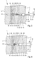
- FIG. 1 shows in a very schematic, not to scale section a preferred embodiment of a proposed insulation system or system 1 for fixing insulation boards 2 by means of fasteners 3 to a building 4. It is shown in FIG Fig. 1 a section or part of the system 1 or an insulating board 2 with a fastening element 3 or in the region of a fastener 3.
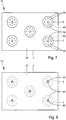
- an insulating panel 2 and each insulation board 2 are assigned a plurality of fasteners 3, as exemplified in plan view Fig. 7 shown.
- the system 1 preferably or usually comprises a plurality of insulating panels 2, which are arranged in particular on impact and / or as continuous as possible insulating layer for insulation of the building 4 form.
- the insulation board 2 is used in particular for thermal insulation or thermal insulation.
- the insulating board 2 is made of a corresponding insulating material, in particular, the insulating board 2 consists essentially or exclusively of this insulating material.
- a foamed insulation material such as expanded polystyrene, o. The like. Used.
- the insulation board 2 is preferably formed at least substantially square or rectangular, as shown in the plan view Fig. 7 seen. However, the insulation board 2 may in principle also have any other shape.
- the insulation board 2 usually has a thickness of several cm, for example, from 6 to 30 cm, usually about 10 to 16 cm on.
- the insulation board 2 is fixed with a flat side on the structure 4. This flat side of the main page is referred to here as Bauwerkseite 2A.
- the building 4 is in particular a building, a wall, a wall, particularly preferably an exterior wall, a ceiling or the like.
- the insulation board 2 can be attached directly to the structure 4 or its surface 4A with its construction side 2A. However, between the structure 4 and the insulation board 2 - at least in regions, but possibly also over the entire surface - a cavity or a layer 4B, such as an intermediate layer or bonding layer, particularly preferably for compensating for unevenness and / or for bonding or gluing, as in Fig. 1 indicated, be provided.
- the insulating board 2 is glued to the structure 4 or its surface 4A or otherwise, in particular material-locking, connected.
- the surface 4A of the structure 4 may be formed in particular by a plaster, masonry or the like.
- the surface 4A can form or represent a facade of the structure 4.
- the fastening element 3 is preferably formed at least substantially flat, lattice-like, rib-like, plate-like and / or plate-like.
- the fastening element 3 is in particular essentially disc-shaped or circular-disk-like, as is apparent Fig. 1 and 7 seen.
- the fastener 3 is preferably at least substantially on the building side 2A of the insulation board 2 or close to the building in the insulation board 2 or adjacent to the building side 2A.
- the fastening element 3 can in principle be arranged raised on the building side 2A or - as in the illustration example - be inserted or pressed into a corresponding depression or recess 2B of the insulating board 2.
- the recess or recess 2B may be prior to attachment the fastening element 3 may be formed on the insulating board 2 or by corresponding impressions of the fastening element 3.
- the depression or recess 2B preferably has, according to the small thickness of the fastening element 3, only a relatively small or corresponding depth.
- the thickness or depth is for example only a few mm, in particular about 1 to 8 mm.
- the fastener 3 is arranged with its main plane or plate plane or main plane parallel or flat on the building side 2A or the insulation board 2 or on or in the insulation board 2 or parallel to the main extension plane or plate plane.
- the fastening element 3 is or is preferably connected by gluing to the insulating board 2, that is glued to the insulating board 2.
- the fastening element 2 is glued on the building side or on the building side 2A or in the recess 2B with the insulation boards 2.
- the fastening element 3 may also have undercuts, recesses 3A o. The like., To allow a particularly good connection, in particular by gluing, with the insulation board 2.
- positive-locking additional connections can also be used, for example one or more spirals, chambers (in Fig. 1 is exemplified such a compound or spiral 8 shown) o.
- the like. Which connect the fastening element 3 with the insulating board 2 in addition to the preferred adhesive connection form-fitting manner.
- the fastening element 3 preferably has a plate-like configuration or a plate section in order to form a relatively large insulating board-side adhesive surface.
- the fastening element 3 or its plate section preferably forms a relatively large adhesive surface in order to adhere the fastening element 3 to the structure 4 can, in particular for a first attachment of the fastener 3 and the associated insulation board 2 on the building. 4
- the fastener 3 is connected to the insulation board 2 before attaching the insulation board 2 to the structure 4.
- Prefabricated units 1A are preferably formed from the insulating panels 2 and the associated fastening elements 3. This takes place, in particular, at the factory or not on site at a construction site, but in particular before the packaging and delivery of the insulation boards 2.
- Fig. 7 shows an example of such a preassembled unit 1A.
- a plurality of fasteners 3 are attached to the associated insulation board 2.
- the insulation board 2 can in principle be provided only with a fastener 3.
- the fastening elements 3 are preferably fastened by gluing to the associated insulating board 2 or connected thereto.
- material or positive connection with the insulation board 2 for example by welding o. The like.
- the fastening elements 3 - at least substantially or completely - be introduced into the insulation board 2, embedded or foamed, particularly preferably close to the building or adjacent to the building side 2A.
- the fastening element 3 is preferably formed as a separate part and / or made of a preferably relatively strong plastic and / or of a different material than the insulating panels 2.
- the fastener 3 is injection molded.
- the fastening element 3 may also be integrally formed with the insulating board 2, for example by a correspondingly reinforced or firmer or solidified, possibly also continuous layer of the insulating board 2 or by local reinforcements, deposits o. The like. Be formed ,
- the fastening element 3 has an opening 3B in order to be able to connect the fastening element 3 to the building 4 by means of a dowel connection.
- the opening 3B is preferably arranged centrally on or in the fastening element 3 and / or in particular already formed in terms of production in the fastening element 3, but may alternatively also be formed or opened on site during attachment to the structure 4, for example by drilling.
- the fastening element 3 has a positioning means, which is formed here by a projection 3C.
- the positioning means is preferably a positioning of the fastener 3 on the insulation board 2, in particular with respect to a preformed opening 2D of the insulation board 2, and / or positioning, guiding and / or abutment of a connecting means, such as a dowel 5 and / or a screw 6 for connection of the fastening element 3 with the structure 4th
- the positioning means or the projection 3C is integrally formed or molded onto the fastening element 3 and arranged on the insulation board side.
- the projection 3C joins on the insulation board side to the opening 3B of the fastening element 3 or forms it.
- the projection 3C is preferably formed sleeve-like or hollow cylindrical and / or thick-walled.
- the positioning means or the projection 3C is provided with an inner insertion bevel 3D.
- This is in particular at least substantially conical. However, this can also be formed by distributed over the circumference guide ribs, bevels o. The like.
- the fastening element 3 is introduced with its positioning means or projection 3C in the associated aperture 2D of the insulation board 2.
- the aperture 2D is formed in particular by a through hole.
- the aperture 2D extends transversely or perpendicular to the plane of the plate and / or connects the two flat sides 2A and 2C of the insulating board 2.
- the positioning means or the projection 3C is preferably relatively short, in particular the axial length is substantially only 0.5 to 4 cm. Positioning means or the projection 3C is preferably formed short in relation to the thickness of the insulation board 2 and the length of the opening 2D. However, the positioning means or the projection 3C can also be made longer, in particular for better guidance.
- the insulation board 2 is first provided with the opening 2D or more perforations 2D, in particular by appropriate drilling.
- the respective fastener 3 with its positioning means or projection 3C in the associated aperture 2D on the building side - ie starting from the building side 2A of the insulation board 2 - the attachment of the fastener 3 and the fasteners 3. introduces.
- the outer diameter of the positioning means or projection 3C is adapted to the clear or inner diameter of the aperture 2D accordingly. This allows a very simple and quick positioning.
- the fixing element 3 correspondingly positioned on the structure side 2A is connected to the insulation board 2, in particular adhesively bonded, as already mentioned.
- the preassembled unit 1A made of insulating board 2 and fastener (s) 3 is produced.
- the diameter of the aperture 2D is more than 25%, in particular more than 50%, larger than the diameter of the opening 3B, so that the insertion of the anchor 5 and the screw 6 or other connecting element facilitates and / or in particular without deformation of the insulating board 2 or of the insulating material through the aperture 2D is made possible and / or so that the aperture 2D can absorb drilling dust or dust during drilling in the building 4.
- the assemblies 1A and the insulation panels 2 provided with the fastening elements 3 are fastened to the structure 4.
- the pre-assembled, so provided with fasteners 3 insulation board 2 or assembly 1A is attached to the structure 4.
- the insulation board 2 is adhered to the structure 4 or its surface 4A.
- a first or alternative or temporary connection of the insulation board 2 is achieved with the structure 4.
- the optional layer 4B is used for bonding and / or compensation of unevenness o. The like.
- this first or temporary connection can also be done in any other suitable manner or alternatively be achieved by holding the respective insulating board 2 on the building 4.
- This (second) connecting the insulation board 2 in addition to the bonding is preferably carried out in all fasteners 3, even if this is described below by way of example only for a fastener 3.
- a hole 4C in the structure 4 is drilled in a first step through the insulation board 2 and the opening 2D and the fastener 3 through into the structure 4 to produce a hole 4C in the structure 4, as exemplified in Fig. 1 shown.
- the corresponding drill is in Fig. 1 not shown.
- the positioning of the drill is made possible or achieved by the positioning means or the projection 3C or the insertion bevel 3D, so that it is very easy to drill through the fastening element 3 into the building 4 from the outside - with the desired depth.
- the dowel 5, preferably with preassembled expansion element, in particular with partially screwed screw 6, is then inserted into the insulation board 2 or its opening 2D.
- This can be done very easily manually and is particularly easy due to the relatively large diameter of the aperture 2D.
- a tool 7 is then preferably used. This is exemplary in Fig. 2 shown, which corresponds to a schematic section (detail) Fig. 1 shows.
- a screwdriver or other available on the site hand tool can be used.
- a tool 7 is used, which is preferably used both for (correct) insertion and for clamping or tightening the dowel connection, in particular for screwing.
- the tool 7 which is used with particular preference, has a tool head 7A, a shank 7B, a first guide section 7C, a second guide section 7D, a first marking means 7E and / or a second marking means 7F.
- the tool head 7A is preferably a bit, a so-called six-round or other insert or polygonal key, which in particular can be brought into positive engagement with the expanding element or the screw 6 or its head 6A and / or preferably is interchangeable.
- the tool 7 or the shaft 7B is preferably designed to be received in a screwdriver or the like, and / or is preferably designed as a polygon, at least in regions.
- the first guide section 7C is preferably formed by a corresponding body, preferably made of plastic, and / or arranged in the region of a receptacle for the tool head 7A.
- the first guide section 7C permits in particular lateral guidance and / or centering of the tool head 7A, in particular for concentric alignment with the screw head 6A.
- the screw 6 is in turn held or guided centrally or coaxially by the fastening element 3 or the opening 3B or the insertion bevel 3D, in particular by means of the dowel 5 or anchor 5 inserted in it.
- the second guide portion 7D is preferably axially adjustable, in particular by means of a grub screw, not shown, o. The like., On the tool 7 or its shaft 7B can be fixed, in particular for adaptation to different Dämmplattendicken.
- the second guide portion 7D allows in particular an additional lateral guide in the opening 2D or in the insulating material when screwing the screw. 6
- the first marking means 7E is preferably formed by a marking, a shoulder or the like.
- the second marking means 7F is preferably formed by a mark, a shoulder, a stop or the like, as in FIG Fig. 2 indicated.
- the two marking means 7E and 7F are preferably axially adjustable, in particular for adaptation to different Dämmplattendicken, anchor lengths and / or screw lengths.
- the axial adjustability can be achieved, in particular, by the first and / or second marking means 7E, 7F being or being adjustable together with the second guide section 7D or being formed by it.
- the marking means 7E, 7F may also be separately formed and / or adjustable.
- Fig. 2 shows in one too Fig. 1
- Fig. 1 Corresponding, schematic section a state in which the dowel 5 is inserted or inserted so far together with the preferably partially screwed into the dowel screw 6 6, for example by means of the tool 7, the front in the direction of insertion of the dowel 5 already in the Near the fastener 3 or projection 3C and the insertion bevel 3D is located.
- the dowel 5 and the screw 6 are still inside on the opening 2D of the insulation board 2, so are not yet centrally guided or aligned. Rather, here the screw 6 or its head 6A and in particular the dowel 5 is still offset radially or transversely to the tool head 7A.
- Fig. 3 shows a state in which the dowel 5 is already inserted or inserted so far, in particular by means of the tool 7, that in the insertion direction front end of the dowel 5 already the fastener 3 and the beginning of the opening 3B of the fastener 3 and Insertion bevel 3D achieved.
- the dowel 5 or its expansion element here the screw 6, and / or another connection means or element of the opening 2D or of the insulation board 2 and of the insulating material the insulation board 2 guided laterally.
- the insertion bevel 3D and subsequent breakthrough 3B then serve in particular for (further) centering or axial positioning or guidance of the anchor 5 and thus also of the screw 6. Accordingly, in the illustration according to FIG Fig. 3 the screw 6 with its head 6A already aligned coaxially in the preferably centrally guided tool head 7A.
- Fig. 4 shows in one too Fig. 1 to 3 Corresponding, schematic section attaching the insulation board 2 and the fastener 3 to the structure 4, wherein the dowel 5 is now fully inserted, the dowel 5 comes with its dowel head 5A to the insertion bevel 3D to the plant.
- This completely introduced state is preferably displayed to a user (not shown) by the first marking means 7E, in the illustrated example in particular in that the marking means 7E lies in the plane of the outside 2C of the insulating board 2, as in FIG Fig. 4 indicated.
- the marking means 7E lies in the plane of the outside 2C of the insulating board 2, as in FIG Fig. 4 indicated.
- a separate tool can be used only for the correct insertion of the anchor 5.
- the separate tool may have a stop as the first marking means 7E, so that only insertion up to a certain depth is possible. The stop can then come into contact, for example, in the correctly or completely inserted state on the outer side 2C of the insulating board 2.
- the spreading of the anchor 5 takes place in the structure 4 or borehole 4C. This is done with the help of the expansion element, in particular by screwing the screw 6.
- the dowel connection is made. This condition is in Fig. 5 in one of the Fig. 1 to 4 corresponding section shown schematically.
- the screw 6 is thus completely screwed into the dowel 5.
- the screwing is done in particular by means of the tool 7.
- This screwed-in state is preferably indicated by the second marking means 7F, here in particular in that a shoulder or a stop lies in the plane of the outer side 2C or comes to rest thereon.
- the screw 6 with its screw head 6A preferably comes to rest on the dowel head 5A and / or on the fastening element 3 or projection 3C or its insertion bevel 3D.
- the bonding of the fastener 3 to the structure 4, for example, by an adhesive bond, a Klebedübel, a Klebeanker o. The like. Take place. In this case, then a corresponding adhesive bucket, adhesive anchor o. The like. Introduced and, for example, with the building 4, in particular in the bore 4C, glued or otherwise connected thereto or anchored therein.
- the fastening element 3 there is a direct connection of the fastening element 3 with the structure 4.
- the fastening element 3 is in turn connected to the insulation board 2, in particular by the pre-assembly already explained above. Accordingly, then the insulation board 2 is fixedly connected via the fastener 3 with the structure 4 and is thereby held sufficiently secure on the building 4 or 4 of the structure.
- the tool 7 is removed and the opening 2D in the insulation board 2 is closed.
- This closing is preferably carried out by a plug 2E, as in Fig. 6 indicated.
- the plug 2E is preferably inserted by clamping into the insulation board 2 or its opening 2D.
- the plug 2E consists of the same insulating material as the insulation board 2 or a similar insulating material. Possibly. can the plug 2E also consist of an insulating material with better thermal insulation than the insulation board 2, since the length of the plug 2E is less than the thickness of the insulation board 2.
- the formation of a thermal bridge in the region of the opening 2D can be avoided or at least reduced.
- the preferred use of the same or similar insulating material for the plug 2E as for the insulation board 2 has the advantage that no introduction of different materials in the insulation board 2 takes place. This is particularly advantageous in terms of an outside cover or outside plastering of the system 1 and the insulation board 2, since otherwise often in the range of openings or fasteners resulting markings can be avoided. Furthermore, the use of this material to the effect that only varietal material in the insulation board 2 is present when the insulation board 2 later must be disposed of once (the fasteners 3 are only on a flat side or the building side 2A, therefore, the Insulating board 2 are removed from the fasteners 3).
- Fig. 6 is indicated schematically that the proposed system 1 or the attached insulation board 2 is preferably covered on the outside, in particular by a plaster 2F.
- This plaster 2F is, in particular, a mineral-based or plastic-based material or construction or the like which is preferably reinforced by a fabric.
- the plaster 2F is preferably made very thin and forms in particular a relation to the insulation or the insulation board 2 relatively hard surface and / or protects the insulation board 2 from environmental influences, such as driving rain, compressive stress, solar radiation o.
- Fig. 7 shows the insulation board 2 in the preassembled state or the preassembled unit 1A from the building side 2A forth in a schematic plan view, as already mentioned.
- the fastening elements 3 are preferably arranged in the region of the corners of the insulating board 2 and / or in the middle of the insulating board 2.
- Fig. 7 the preferred plate-like design of the fasteners 3 can be seen.
- Fig. 8 shows the preassembled insulation board 2 or preassembled unit 1A in a plan view of the outside 2C ago.
- the openings 2D of the insulation board 2 can be closed optimally and well insulated. Defects in the insulation board 2 can be avoided. In particular, no thermal bridge is formed. There is no hindrance to diffusion processes. Furthermore, optimal sound insulation properties can be achieved.
- Another advantage is that the recyclability is very high, since no "contamination" of the insulation boards 2 by introducing foreign substances into the insulation boards 2 takes place.
- Restraining stresses in the insulation boards 2 are avoided because deformations of the insulation boards 2 are not hindered.
- the commercial dowels can also be used in different Dämmplattendicken because the dowel length is independent.
- the dowels 5 which can be used according to the proposal allow for logistical advantages, in particular a low transport volume and / or lower stocks of stock, since standard dowels can be used. Next, only small volumes of dowels 5 must be handled at the construction site.
- the proposed solution prevents damage to the insulation boards 2 and the outside 2C during assembly on the structure 4.
- an otherwise usual rework or trowelling can be omitted.
- an otherwise often occurring "milling dust” or leakage of drilling dust or the like during drilling can be avoided, in particular in the case of factory-formed formation of the perforations 2D.
- the relatively large diameter of the apertures 2D in the insulation boards 2 allows the inclusion of drilling dust, so that unwanted contamination and leakage of dust o. The like. Can be avoided.
- Another advantage of the present invention is that the previously usual process in the attachment of the insulation panels 2 on the structure 4 can be obtained.
- the insulation board 2 can be adhered to the building 4 as before.
- the provided with the apertures 2D insulation boards 2 already give an optimal dowel grid, so that an otherwise often required signs of mounting positions o. The like. Is not required.
- the design of the fastening elements 3 can be matched to desired load capacities and desired fixing areas or connecting areas. Furthermore, the position of the fastening elements 3 on the insulating board 2 can be optimally adapted to a desired arrangement, for example for fixing the edge of the insulating board 2.
- Very high loads can be achieved with small dowel quantities per square meter.
- the factory design of the openings 2D leads to very clean, defined mounting holes in the insulation board 2 and also facilitates handling when mounting on the structure 4. Alternatively or additionally, this also allows a perfect fit of the plug 2E or supported.
- the connecting elements such as the dowels 5 and / or screws 6, are supplied from the outside 2C of the insulation boards 2, or introduced in contrast to the fastening elements 3, which are attached from the rear or building side 2A ago.
- the fastening elements 3 are preferably made of polyamide, a glass fiber reinforced polyamide o. The like.
- the fastening elements 3 are preferably adhesive and / or provided with different surface roughnesses or with a surface or surface roughness optimized for adhesion.
- fastening elements 3 are fixed at the factory with a specific bias, in particular to harden adhesive when adhering to the insulation boards 2.
- a mechanical additional fixing can be used, for example a spiral 8 (by way of example in FIG Fig. 1 shown), nails, brackets, o. The like.
- the particularly preferred sinking of the fasteners 3 in the building side 2A or by the insertion of the fasteners 3 in corresponding recesses or recesses 2B of the insulation board 2 is preferably a smooth site side 2A of the preassembled insulation boards 2 and 1A units achieved. This is particularly advantageous with regard to a good stackability and / or with regard to a smooth or uniform adhesion to the structure 4.
- the recesses or recesses 2B preferably provided serve, in particular, to be able to receive the respective fastening element 3 in a position-oriented and / or centric manner, in particular relative to the associated opening 2D in the insulating panel 2.
- the recesses or recesses 2B can accordingly also represent or form positioning means in the sense of the projections 3C.
- FIGS. 9 and 10 a further embodiment of the proposed fastener 3 and the preassembled unit 1A explained in more detail, with only essential differences compared to the previous embodiment or significant new aspects of this further embodiment is discussed in more detail.
- the previous statements and explanations therefore apply in particular according to or supplementary, even if the relevant description is not repeated.
- Fig. 9 shows the proposed construction unit 1A consisting of an insulating board 2 and one or more associated fasteners 3 in a plan view of the building side.
- Fig. 10 shows a schematic section along the line XX of Fig. 9 ,
- the fastening element 3 is preferably elongated, in particular at least substantially rectangular or formed as a narrow strip.
- the fastening element 3 preferably has a particular elongated and / or substantially rectangular plate portion, which may be provided with perforations 3B if necessary.
- the fastening element 3 or its plate section preferably has at least one reinforcing element 3E.
- the reinforcing element 3E serves in particular to stiffen the plate section of the fastening element 3.
- the reinforcing element 3E preferably extends at least substantially in the longitudinal extension of the fastening element 3 or plate section.
- the reinforcing element 3E is preferably formed rib-like or web-like or thigh-like.
- the reinforcing element 3E preferably protrudes from or protrudes from the fastening element 3 or its plate section and / or preferably encloses an angle with the plate section or a main plane of the fastening element 3.
- an effective slope transverse to the plate or main plane of the fastener 3 can be achieved.
- the reinforcing element 3E can be arranged or formed as required on the building side and / or on the insulating board side of the fastening element 3.
- the reinforcing element 3E is integrally formed on the fastening element 3 or integrally formed therewith.
- a plurality of reinforcing elements 3E may also be provided on a fastening element 3, optionally on one side of the fastening element 3 or on both sides of the fastening element 3.
- the fastening elements 3 preferably each have two reinforcing elements 3E each on both the building side and on the Dämmplattenseite on.
- Fig. 9 In the plan view according to Fig. 9 is an example of the right fastener 3 indicated that this by means of one or more, here two positive connections or spirals 8 o. The like. (In addition) may be connected to the associated insulation board 2 (as in Fig. 1 indicated).
- the preferably elongated or latch-like design of the fastener 3, in particular in combination with the reinforcing elements 3E, allows a relatively large force transmission and / or plate-like stiffening, so the relatively few fasteners 3, here for example only two fasteners 3, for fixing a conventional insulation board 2 of, for example, 50 x 100 cm and / or even with very large surface design of the fasteners 3 and / or relatively large length of the fasteners 3, if necessary, only one dowel connection per fastener 3 is sufficient or sufficient. Accordingly, the cost of material and installation is relatively low.
- the insulation board 2 does not have to have a depression or recess 2B for receiving the respective fastening element 3 or plate section of the fastening element 3. Rather, the fastener 3 can be arranged with its plate portion on the building side flat side of the insulation board 2, in particular glued.
- the insulation board side reinforcing elements 3E can preferably be pressed into the relatively soft insulating material and thereby support a positioning of the respective fastening element 3 and / or a connection of the respective fastening element 3, for example by temporary fixing for the adhesion to the insulating board 2.
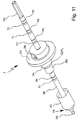
- Fig. 11 and 12 show the tool 7 according to another or more detailed embodiment.
- Fig. 11 shows the tool 7 in a perspective view.
- Fig. 12 shows the tool 7 in a schematic longitudinal section.
- the shaft 7B is preferably at least substantially rod-shaped or bolt-shaped and / or at least substantially cylindrical in the illustrated embodiment.
- the shaft 7B is preferably provided at the front or tool head end with a connecting means, such as an inner or outer thread o. The like., For releasably holding the tool head 7A.
- the tool 7 or the tool head 7A preferably has a front (insulation board side) end 7G with a driving profile or engagement section for the particular rotationally fixed coupling with a screw 6 and a screw head 6A.
- a driving profile or engagement section for the particular rotationally fixed coupling with a screw 6 and a screw head 6A.
- As entrainment profile in particular a polygonal, polygonal, polygonal or external polygon, crosshead, flat head o. The like. Be provided.
- the end 7G or the engaging portion is preferably designed to drive a connecting element, such as the dowel 5 and / or the screw 6, into the fastening element 3 or structure 4 or the bore 4C, in particular before another insertion, for example, by driving or screwing in a spreading element, such as the screw 6 o.
- a connecting element such as the dowel 5 and / or the screw 6
- the tool head 7A or the end 7G is preferably designed such that it or together with the associated connecting element or, as the screw 6 and the screw head 6A, preferably by axial Traumschzube admire causes a radial centering and / or a rotationally fixed engagement or supports, in particular by appropriate conical design, conical or inclined surfaces or the like.
- the tool head 7A or the end 7G is preferably exchangeable, in particular latching or threaded with the tool 7 or shaft 7B connectable.
- the end 7G or tool head 7A may be a so-called screw bit or a pieceable bit.
- the tool head 7A preferably has a connecting section 7H, which can be detachably connected to a holding section, in particular an internal thread or external thread of the tool 7 or shaft 7B.
- a connecting section 7H which can be detachably connected to a holding section, in particular an internal thread or external thread of the tool 7 or shaft 7B.
- the first guide section 7C preferably serves for lateral guidance of the tool 7 or tool head 7A or its end 7G in the insulation board 2 or bore or opening 2D.
- the first guide section 7C preferably has a diameter adapted to the bore or opening 2D, in particular so that the tool head 7A is guided laterally or centrally in the bore or opening 2D, in particular with at most a slight clearance or virtually no play.
- the first guide portion 7C may also have a certain excess.
- the diameter of the first guide section 7C is preferably larger than the tool head 7A and / or shaft 7B, in particular at least 50% larger, preferably at least substantially substantially twice or three times as large.
- the first guide portion 7C is preferably at least substantially cylindrical and / or provided with a particular conical bevel at the front axial end to facilitate insertion into the bore or aperture 2D.
- the first guide section 7C is preferably exchangeable, in particular together with the tool head 7A.
- the first guide section 7C is permanently or permanently connected to the tool head 7A, the end 7G or connecting section 7H.
- the first guide section 7C is plugged or clamped onto the tool head 7A or the connecting section 7H.
- the first guide section 7C can also be designed or used as a handle for exchanging the tool head 7A or the end 7G, for example in order to unscrew the tool head 7A from the shaft 7B or screw it onto it.
- the first guide portion 7C is preferably made of plastic.
- the second guide portion 7D is preferably spaced from and held by the first guide portion 7C on the shaft 7B.
- the second guide section 7D is preferably axially adjustable or fixable in different axial positions on the shaft 7B. In the illustrated example, this is preferably realized by corresponding engagement possibilities, such as depressions or grooves 7J, in particular circumferential grooves on the shaft 7B and an adjustable engagement element, such as a threaded pin 7R on the second guide portion 7D.
- the threaded pin 7R is preferably guided on the second guide portion 7D threaded radially adjustable and can engage with a preferably conical tip in an associated recess, groove 7J o. The like.
- the grooves 7J are preferably provided with corresponding markings 7K or designations, in particular for the identification of the associated insulation board thickness, for example in millimeters. These markings 7K are attached to the shaft 7B in the illustrated example.
- a front edge of the second guide section 7D preferably forms the first marking means 7E, in particular to indicate to a user a sufficient insertion or insertion of a dowel 5, in particular with a pre-mounted screw 6, into the associated bore 4C or the fastening element 3.
- the second guide section 7D preferably has a conical or beveled section 7L, which tapers in particular towards the insulation board 2 or the tool head 7A or the end 7G.
- the section 7L preferably forms a transition between a first region 7M of smaller diameter and a second region 7N of larger diameter of the second guide section 7D.
- the first region 7M preferably serves for a first lateral guidance of the tool 7 in the case of a simple insertion of the second guide section 7D into the insulation board 2 or its bore 2D or during the (complete) insertion or insertion of the anchor 5 into the fastening element 3 and itself subsequent building 4.
- the second region 7N preferably serves for laterally guiding the tool 7 when driving or screwing in the screw 6 or another spreading element into the plug 5.
- the tool 7 or the second guide section 7C preferably has a stop or abutment plate 7P for abutment on a flat side or outer side 2C of the insulation boards 2 when the screw 6 has been completely or sufficiently inserted or anchoring has occurred.
- the stop preferably forms the second marking means 7F in order to indicate to a user the complete insertion or screwing in of the screw 6 or of another spreading element into the associated dowel 5.
- the abovementioned stop is preferably formed by the second guide section 7D, in particular a corresponding flange section of the second guide section 7D, or a stop plate 7P arranged thereon or held by it.
- the stopper plate 7P is screwed to the second guide portion 7D.
- the diameter of the stop or stop plate 7P is preferably more than 5 cm, in particular more than 8 cm, particularly preferably more than 10 cm, in the illustrated example about 12 cm. Due to the large surface of the stop or abutment plate 7P, undesired impressions into the outer side 2C of the insulating panels 2 upon reaching the end position of the tool 7 can be prevented.
- the tool 7 or the shaft 7B preferably has at its rear end, that is to say the end facing away from the tool head 7A, an end section 7Q which is designed in particular as a polygon for clamping or rotationally fixed connection to a drive (not shown) (eg drill, cordless screwdriver or the like). ) on.
- a drive not shown
- the end portion 7Q can also form a striking end for the action of a striking element, such as a hammer or the like, around the tool 7 and thus the associated connecting element or expansion element, such as the dowel 5 and / or the screw 6, in the Introduce fastener 3 and the associated structure 4 or drive or beat.
- a striking element such as a hammer or the like
- the associated connecting element or expansion element such as the dowel 5 and / or the screw 6, in the Introduce fastener 3 and the associated structure 4 or drive or beat.
- the end portion 7Q may also be formed as a correspondingly widespread head.
- the proposed tool 7 is preferably used for attachment of insulation boards 2 with building-side or close to the building fasteners 3 to the structure 4.
- the tool 7 or its tool head 7A is guided in a corresponding hole or opening 2D of the insulating material of the respective insulating board 2 for connection, in particular dowelling, of the hole or opening 2D associated fastener 3 with the building 4 side or center. This allows a very simple and intuitive handling and a very fast installation.
- the force for inserting the dowel 5 in particular depends on a corresponding adaptation of the diameter of the opening 3B of the fastening element 3 and the diameter of the bore 4C in the structure 4 to the diameter of the dowel 5 before the (complete) spreading or screwing in of the screw 6 ,
- the first marking means 7E for indicating a complete insertion of the anchor 5 is only optional.
- the complete insertion of the anchor 5 can also be indicated to a user that further insertion of the tool 7 is not possible or the resistance increases accordingly. This is sensed by the user when the dowel head 5A abuts on the fastening element 3 or on the insertion bevel 3D and can not be inserted any further.
Landscapes
- Engineering & Computer Science (AREA)
- Mechanical Engineering (AREA)
- Physics & Mathematics (AREA)
- Architecture (AREA)
- Acoustics & Sound (AREA)
- Electromagnetism (AREA)
- Civil Engineering (AREA)
- Structural Engineering (AREA)
- Building Environments (AREA)
- Joining Of Building Structures In Genera (AREA)
- Finishing Walls (AREA)
Claims (13)
- Système (1) destiné à la fixation de panneaux isolants (2) au moyen d'éléments de fixation (3) sur une construction (4), avec des panneaux isolants (2) qui sont raccordés à des éléments de fixation (3) par liaison de matière et/ou de forme,
les éléments de fixation (3) présentant respectivement une découpe (3B) pour le raccordement de l'élément de fixation (3) respectif à la construction (4),
les éléments de fixation (3) étant disposés au moins essentiellement côté construction ou à proximité de la construction sur ou dans les panneaux isolants (2), et
les éléments de fixation (3) présentant respectivement une saillie (3C) formée d'un seul tenant, se raccordant à la découpe (3B) côté panneau isolant, les éléments de fixation (3) engrenant avec la saillie (3C) respectivement dans un alésage ou respectivement une découpe (2D) du panneau isolant (2), ou respectivement étant disposés du fait de la saillie (3C) en tant que moyens de positionnement de façon coaxiale à ceux-ci,
caractérisé
en ce que la saillie (3C) présente un chanfrein d'introduction (3D) côté panneau isolant, le chanfrein d'introduction étant approprié pour qu'une cheville avec une zone de tête évasée vienne en appui contre le chanfrein d'introduction (3D) côté panneau isolant. - Système selon la revendication 1, caractérisé en ce que les éléments de fixation (3) sont au moins essentiellement constitués de façon plate, en forme de grille, de nervure, de plaque et/ou de plateau.
- Système selon l'une des revendications précédentes, caractérisé en ce que les éléments de fixation (3) sont fabriqués dans un matériau qui est plus dur, plus rigide et/ou plus raide que le matériau isolant des panneaux isolants (2).
- Système selon l'une des revendications précédentes, caractérisé en ce que les éléments de fixation (3) sont raccordés par collage aux panneaux isolants (2).
- Système selon l'une des revendications précédentes, caractérisé en ce que les panneaux isolants (2) et/ou les éléments de fixation (3) présentent des découpes (2D, 3B) de telle sorte que les éléments de fixation (3) peuvent être raccordés à la construction (4), en particulier au moyen de chevilles (5) et/ou de vis (6).
- Système selon l'une des revendications précédentes, caractérisé en ce que les panneaux isolants (2) présentent respectivement des alésages ou respectivement des découpes (2D), le matériau isolant des panneaux isolants (2) limitant les alésages ou respectivement les découpes (2D) formant un guidage pour un outil (7) pour le raccordement des éléments de fixation (3) à la construction (4), en particulier au moyen de chevilles (5) et/ou de vis (6).
- Système selon l'une des revendications précédentes, caractérisé en ce que la saillie (3C) est constituée en forme de douille et/ou de paroi épaisse, et/ou en ce que le chanfrein d'introduction (3D) est constitué de façon conique.
- Système selon l'une des revendications précédentes, caractérisé en ce que les éléments de fixation (3) sont disposés dans les angles et/ou au milieu de chaque panneau isolant (2).
- Procédé de fixation d'un panneau isolant (2) sur une construction (4) au moyen d'un élément de fixation (3),
l'élément de fixation (3) étant au moins essentiellement constitué de façon plate, en forme de plaque et/ou de plateau, et
l'élément de fixation (3) présentant une découpe (3B) pour le raccordement de l'élément de fixation (3) à la construction (4),
caractérisé
en ce que l'élément de fixation (3) présente une saillie (3C) formée d'un seul tenant, se raccordant à la découpe (3B) côté panneau isolant, avec un chanfrein d'introduction (3D) côté panneau isolant, et est affecté à un alésage ou respectivement une découpe (2D) du panneau isolant (2),
en ce que l'élément de fixation (3) est mis en place sur le panneau isolant (2) côté construction ou près de la construction ou est mis en place dans le panneau isolant (2), et est disposé au moyen de la saillie (3C) de façon coaxiale à l'alésage ou respectivement à la découpe (2D) du panneau isolant (2) de telle sorte que le panneau isolant (2) est raccordé par liaison de matière et/ou de forme à l'élément de fixation (3), et
en ce que l'élément de fixation (3) est assemblé par chevillage à la construction (4) à travers la saillie (3C) et la découpe (3B), une cheville avec une zone de tête évasée venant, côté panneau isolant, en appui contre le chanfrein d'introduction. - Procédé selon la revendication 9, caractérisé en ce que l'élément de fixation (3) est raccordé par collage au panneau isolant (2).
- Procédé selon la revendication 9 ou 10, caractérisé en ce que l'élément de fixation (3) est raccordé au panneau isolant (2) avant la fixation du panneau isolant (2) sur la construction (4).
- Procédé selon l'une des revendications 9 à 11, caractérisé en ce que l'élément de fixation (3) est disposé avec son plan d'extension principal parallèlement au plan d'extension principal du panneau isolant (2) sur ou respectivement dans le panneau isolant (2).
- Procédé selon l'une des revendications 9 à 12, caractérisé en ce que le panneau isolant (2) muni de l'élément de fixation (3) est collé sur la construction (4) et puis raccordé à la construction (4) par un raccordement chevillé.
Priority Applications (1)
| Application Number | Priority Date | Filing Date | Title |
|---|---|---|---|
| EP12000062.5A EP2474685B1 (fr) | 2011-01-10 | 2012-01-06 | Système, outil et procédés de fixation de plaques isolantes équipées d'éléments de fixation pré-montés sur un bâtiment |
Applications Claiming Priority (2)
| Application Number | Priority Date | Filing Date | Title |
|---|---|---|---|
| EP11000116 | 2011-01-10 | ||
| EP12000062.5A EP2474685B1 (fr) | 2011-01-10 | 2012-01-06 | Système, outil et procédés de fixation de plaques isolantes équipées d'éléments de fixation pré-montés sur un bâtiment |
Publications (3)
| Publication Number | Publication Date |
|---|---|
| EP2474685A2 EP2474685A2 (fr) | 2012-07-11 |
| EP2474685A3 EP2474685A3 (fr) | 2014-12-10 |
| EP2474685B1 true EP2474685B1 (fr) | 2017-04-26 |
Family
ID=44070658
Family Applications (1)
| Application Number | Title | Priority Date | Filing Date |
|---|---|---|---|
| EP12000062.5A Active EP2474685B1 (fr) | 2011-01-10 | 2012-01-06 | Système, outil et procédés de fixation de plaques isolantes équipées d'éléments de fixation pré-montés sur un bâtiment |
Country Status (1)
| Country | Link |
|---|---|
| EP (1) | EP2474685B1 (fr) |
Cited By (1)
| Publication number | Priority date | Publication date | Assignee | Title |
|---|---|---|---|---|
| CN110644631A (zh) * | 2019-08-28 | 2020-01-03 | 河南职业技术学院 | 建筑节能复合墙体连接桥 |
Families Citing this family (8)
| Publication number | Priority date | Publication date | Assignee | Title |
|---|---|---|---|---|
| EP3099865B1 (fr) | 2014-01-27 | 2018-06-06 | EJOT Baubefestigungen GmbH | Plaque isolante, procédé de fabrication d'une plaque isolante et utilisation d'une plaque isolante |
| AT14776U1 (de) * | 2014-09-22 | 2016-05-15 | Fröwis Ag | Anordnung aus einer Dämmstoffplatte und einem Dämmstoffhalter |
| DE202015005171U1 (de) | 2015-06-25 | 2015-08-26 | Ejot Baubefestigungen Gmbh | Dämmplatte und System zur Wärmedämmung |
| CN106436933B (zh) * | 2016-11-01 | 2018-12-28 | 重庆方浩建筑保温材料有限公司万盛分公司 | 一种外顶式保温板固定连接装置 |
| GR20200100377A (el) * | 2020-06-29 | 2022-01-13 | Ιωαννης Γεωργιου Εργαζακης | Πλακα θερμοπροσοψης |
| USD1034158S1 (en) | 2020-08-03 | 2024-07-09 | Simpson Strong-Tie Company Inc. | Fastener sleeve |
| USD986044S1 (en) | 2020-08-03 | 2023-05-16 | Simpson Strong-Tie Company Inc. | Fastener sleeve |
| EP4043657A1 (fr) * | 2020-08-03 | 2022-08-17 | Simpson Strong-Tie Company, Inc. | Manchon de fixation, systeme et procede d'installation |
Citations (1)
| Publication number | Priority date | Publication date | Assignee | Title |
|---|---|---|---|---|
| US4653246A (en) * | 1984-01-05 | 1987-03-31 | Hepler Jacque P | Insulation board for attachment to walls |
Family Cites Families (13)
| Publication number | Priority date | Publication date | Assignee | Title |
|---|---|---|---|---|
| FR2343869A1 (fr) * | 1976-03-12 | 1977-10-07 | Sabes John | Latte isolante prefabriquee |
| CA2030011A1 (fr) * | 1990-11-14 | 1992-05-15 | Peter A.D. Mill | Panneau de construction composite |
| FR2694319B1 (fr) | 1992-07-30 | 1995-02-24 | Sicof Ste Indle Cale Facade | Panneau pour habillage isolant des parois de bâtiments. |
| DE19536171A1 (de) | 1995-09-28 | 1997-04-03 | Ejot Kunststofftech Gmbh | Befestigungselement für die Befestigung von wärmeisolierenden Materialien |
| DE59811519D1 (de) * | 1998-01-08 | 2004-07-08 | Peter Kellner | Verwendung von trägerelementen zur befestigung von unterkonstruktionen |
| DE19840521C1 (de) | 1998-09-04 | 2000-02-10 | Ejot Kunststofftech Gmbh | Befestigungselement zur Befestigung von Dämmstoffplatten |
| DE10000059A1 (de) | 2000-01-03 | 2001-10-18 | Peter Kellner | Befestigungselement zur Befestigung von Fassadenelementen |
| AT411077B (de) | 2000-12-01 | 2003-09-25 | Franz Stransky Ges M B H A 115 | Verfahren zum befestigen von wärmedämmplatten an einer wand oder einer decke |
| PT1870533E (pt) | 2001-12-05 | 2012-06-25 | Ejot Gmbh & Co Kg | Processo para a montagem de placas de material isolante |
| DE102004019782A1 (de) | 2004-04-23 | 2005-11-17 | Veit Dennert Kg Baustoffbetriebe | Wärmedämmplatte für Aussenfassaden, insbesondere mineralische Schaumbetonplatte |
| DE102007000758A1 (de) | 2007-09-20 | 2009-04-09 | Hilti Aktiengesellschaft | Befestigungselement für die Befestigung von Dämmstoffplatten an einer Unterkonstruktion |
| DE202008016581U1 (de) | 2008-12-15 | 2009-03-05 | Greutol Ag | Verkleidungssystem |
| DE102009006769A1 (de) | 2009-01-30 | 2010-08-05 | Fischerwerke Gmbh & Co. Kg | Dämmstoffhalter |
-
2012
- 2012-01-06 EP EP12000062.5A patent/EP2474685B1/fr active Active
Patent Citations (1)
| Publication number | Priority date | Publication date | Assignee | Title |
|---|---|---|---|---|
| US4653246A (en) * | 1984-01-05 | 1987-03-31 | Hepler Jacque P | Insulation board for attachment to walls |
Cited By (2)
| Publication number | Priority date | Publication date | Assignee | Title |
|---|---|---|---|---|
| CN110644631A (zh) * | 2019-08-28 | 2020-01-03 | 河南职业技术学院 | 建筑节能复合墙体连接桥 |
| CN110644631B (zh) * | 2019-08-28 | 2020-11-17 | 河南职业技术学院 | 建筑节能复合墙体连接桥 |
Also Published As
| Publication number | Publication date |
|---|---|
| EP2474685A3 (fr) | 2014-12-10 |
| EP2474685A2 (fr) | 2012-07-11 |
Similar Documents
| Publication | Publication Date | Title |
|---|---|---|
| EP2474685B1 (fr) | Système, outil et procédés de fixation de plaques isolantes équipées d'éléments de fixation pré-montés sur un bâtiment | |
| EP3314064B1 (fr) | Panneau isolant et système pour isolation thermique | |
| EP1870533B1 (fr) | Procédé de montage de plaques de matériau isolant | |
| DE3011019C2 (fr) | ||
| EP1818477A2 (fr) | Système de fixation pour composants sur un sous-sol porteur ainsi que procédé et aide au montage destinés à l'installation du système de fixation | |
| EP2666919B1 (fr) | Procédé et système de fixation pour le montage de plaques d'isolant sur une surface de support | |
| DE10041299B4 (de) | Befestigungssystem | |
| EP0921252A2 (fr) | Elément de fixation pour la fixation à distance de lattes, profilés, panneaux ou similaires sur un support fix, guide de perçage pour trous dans un fond, pour l'insertion d'éléments de fixation et procédé pour la fixation à distance à l'aide d'un tel élément de fixation | |
| CH699766A2 (de) | Rahmenanschlussteil zur Befestigung an einem Rahmen. | |
| EP1693530A1 (fr) | Fixation à pièces multiples pour panneaux d'isolation | |
| WO2017153049A1 (fr) | Élément d'écartement et dispositif de fixation pour des parties à fixer sur un bâtiment à travers une façade | |
| DE102006042052B4 (de) | Isolierplattendübel | |
| EP2639374B1 (fr) | Fixation de plaques d'isolation | |
| EP1624199B1 (fr) | Dispositif de fixation pour des systèmes composites d'isolation thermique | |
| EP3258026B1 (fr) | Panneau isolant, procédé de fabrication d'un panneau isolant et utilisation d'un panneau isolant | |
| DE202012006363U1 (de) | System, Befestigungselement und Werkzeug zur Befestigung von Dämmplatten | |
| EP3138974A1 (fr) | Procédé d'application de plaques de matériau isolant ou isolant similaire sur un fond porteur et système de fixation associé | |
| EP1591602B1 (fr) | Système pour fixer des éléments de construction sur un mur | |
| EP3354812A1 (fr) | Système de fixation d'une plaque isolante | |
| DE102016124992A1 (de) | Verfahren, Schutzhülse und Kit zur Befestigung einer Dämmplatte | |
| EP3995661B1 (fr) | Cadres de fenêtre ou de porte pourvus d'éléments coulissants et leur collage à la maçonnerie, ainsi que procédé de montage associé | |
| LU102834B1 (de) | Rahmeneinfassungsvorrichtung zum Einfassen eines Rahmens in eine Laibung | |
| DE19926259A1 (de) | Dämmplatte und Formwerkzeug zur Herstellung einer Dämmplatte | |
| DE102021117051A1 (de) | Rahmeneinfassungsvorrichtung zum Einfassen eines Rahmens in eine Laibung | |
| DE202014009615U1 (de) | Befestigungsvorrichtung zur Befestigung eines Dämmstoffs |
Legal Events
| Date | Code | Title | Description |
|---|---|---|---|
| PUAI | Public reference made under article 153(3) epc to a published international application that has entered the european phase |
Free format text: ORIGINAL CODE: 0009012 |
|
| AK | Designated contracting states |
Kind code of ref document: A2 Designated state(s): AL AT BE BG CH CY CZ DE DK EE ES FI FR GB GR HR HU IE IS IT LI LT LU LV MC MK MT NL NO PL PT RO RS SE SI SK SM TR |
|
| AX | Request for extension of the european patent |
Extension state: BA ME |
|
| RIC1 | Information provided on ipc code assigned before grant |
Ipc: B25B 31/00 20060101ALN20140528BHEP Ipc: B25B 13/48 20060101ALI20140528BHEP Ipc: E04B 1/76 20060101AFI20140528BHEP Ipc: B25B 23/00 20060101ALN20140528BHEP Ipc: F16B 5/02 20060101ALN20140528BHEP |
|
| PUAL | Search report despatched |
Free format text: ORIGINAL CODE: 0009013 |
|
| AK | Designated contracting states |
Kind code of ref document: A3 Designated state(s): AL AT BE BG CH CY CZ DE DK EE ES FI FR GB GR HR HU IE IS IT LI LT LU LV MC MK MT NL NO PL PT RO RS SE SI SK SM TR |
|
| AX | Request for extension of the european patent |
Extension state: BA ME |
|
| RIC1 | Information provided on ipc code assigned before grant |
Ipc: B25B 31/00 20060101ALN20141104BHEP Ipc: B25B 13/48 20060101ALI20141104BHEP Ipc: E04B 1/76 20060101AFI20141104BHEP Ipc: B25B 23/00 20060101ALN20141104BHEP Ipc: F16B 5/02 20060101ALN20141104BHEP |
|
| 17P | Request for examination filed |
Effective date: 20150609 |
|
| RBV | Designated contracting states (corrected) |
Designated state(s): AL AT BE BG CH CY CZ DE DK EE ES FI FR GB GR HR HU IE IS IT LI LT LU LV MC MK MT NL NO PL PT RO RS SE SI SK SM TR |
|
| RAP1 | Party data changed (applicant data changed or rights of an application transferred) |
Owner name: EJOT BAUBEFESTIGUNGEN GMBH |
|
| RIN1 | Information on inventor provided before grant (corrected) |
Inventor name: EJOT BAUBEFESTIGUNGEN GMBH |
|
| REG | Reference to a national code |
Ref country code: DE Ref legal event code: R079 Ref document number: 502012010138 Country of ref document: DE Free format text: PREVIOUS MAIN CLASS: E04F0013080000 Ipc: E04B0001760000 |
|
| GRAP | Despatch of communication of intention to grant a patent |
Free format text: ORIGINAL CODE: EPIDOSNIGR1 |
|
| RIC1 | Information provided on ipc code assigned before grant |
Ipc: B25B 31/00 20060101ALN20161122BHEP Ipc: E04B 1/76 20060101AFI20161122BHEP Ipc: F16B 5/02 20060101ALN20161122BHEP Ipc: B25B 23/00 20060101ALN20161122BHEP Ipc: B25B 13/48 20060101ALI20161122BHEP |
|
| RIC1 | Information provided on ipc code assigned before grant |
Ipc: F16B 5/02 20060101ALN20161207BHEP Ipc: E04B 1/76 20060101AFI20161207BHEP Ipc: B25B 13/48 20060101ALI20161207BHEP Ipc: B25B 31/00 20060101ALN20161207BHEP Ipc: B25B 23/00 20060101ALN20161207BHEP |
|
| INTG | Intention to grant announced |
Effective date: 20161221 |
|
| GRAS | Grant fee paid |
Free format text: ORIGINAL CODE: EPIDOSNIGR3 |
|
| GRAA | (expected) grant |
Free format text: ORIGINAL CODE: 0009210 |
|
| AK | Designated contracting states |
Kind code of ref document: B1 Designated state(s): AL AT BE BG CH CY CZ DE DK EE ES FI FR GB GR HR HU IE IS IT LI LT LU LV MC MK MT NL NO PL PT RO RS SE SI SK SM TR |
|
| REG | Reference to a national code |
Ref country code: GB Ref legal event code: FG4D Free format text: NOT ENGLISH |
|
| RIN1 | Information on inventor provided before grant (corrected) |
Inventor name: TIEMANN, JOCHIM |
|
| REG | Reference to a national code |
Ref country code: CH Ref legal event code: EP |
|
| REG | Reference to a national code |
Ref country code: AT Ref legal event code: REF Ref document number: 888002 Country of ref document: AT Kind code of ref document: T Effective date: 20170515 |
|
| REG | Reference to a national code |
Ref country code: IE Ref legal event code: FG4D Free format text: LANGUAGE OF EP DOCUMENT: GERMAN |
|
| REG | Reference to a national code |
Ref country code: DE Ref legal event code: R096 Ref document number: 502012010138 Country of ref document: DE |
|
| REG | Reference to a national code |
Ref country code: NL Ref legal event code: FP |
|
| REG | Reference to a national code |
Ref country code: LT Ref legal event code: MG4D |
|
| PG25 | Lapsed in a contracting state [announced via postgrant information from national office to epo] |
Ref country code: LT Free format text: LAPSE BECAUSE OF FAILURE TO SUBMIT A TRANSLATION OF THE DESCRIPTION OR TO PAY THE FEE WITHIN THE PRESCRIBED TIME-LIMIT Effective date: 20170426 Ref country code: NO Free format text: LAPSE BECAUSE OF FAILURE TO SUBMIT A TRANSLATION OF THE DESCRIPTION OR TO PAY THE FEE WITHIN THE PRESCRIBED TIME-LIMIT Effective date: 20170726 Ref country code: GR Free format text: LAPSE BECAUSE OF FAILURE TO SUBMIT A TRANSLATION OF THE DESCRIPTION OR TO PAY THE FEE WITHIN THE PRESCRIBED TIME-LIMIT Effective date: 20170727 Ref country code: HR Free format text: LAPSE BECAUSE OF FAILURE TO SUBMIT A TRANSLATION OF THE DESCRIPTION OR TO PAY THE FEE WITHIN THE PRESCRIBED TIME-LIMIT Effective date: 20170426 Ref country code: ES Free format text: LAPSE BECAUSE OF FAILURE TO SUBMIT A TRANSLATION OF THE DESCRIPTION OR TO PAY THE FEE WITHIN THE PRESCRIBED TIME-LIMIT Effective date: 20170426 Ref country code: FI Free format text: LAPSE BECAUSE OF FAILURE TO SUBMIT A TRANSLATION OF THE DESCRIPTION OR TO PAY THE FEE WITHIN THE PRESCRIBED TIME-LIMIT Effective date: 20170426 |
|
| PG25 | Lapsed in a contracting state [announced via postgrant information from national office to epo] |
Ref country code: PL Free format text: LAPSE BECAUSE OF FAILURE TO SUBMIT A TRANSLATION OF THE DESCRIPTION OR TO PAY THE FEE WITHIN THE PRESCRIBED TIME-LIMIT Effective date: 20170426 Ref country code: SE Free format text: LAPSE BECAUSE OF FAILURE TO SUBMIT A TRANSLATION OF THE DESCRIPTION OR TO PAY THE FEE WITHIN THE PRESCRIBED TIME-LIMIT Effective date: 20170426 Ref country code: IS Free format text: LAPSE BECAUSE OF FAILURE TO SUBMIT A TRANSLATION OF THE DESCRIPTION OR TO PAY THE FEE WITHIN THE PRESCRIBED TIME-LIMIT Effective date: 20170826 Ref country code: BG Free format text: LAPSE BECAUSE OF FAILURE TO SUBMIT A TRANSLATION OF THE DESCRIPTION OR TO PAY THE FEE WITHIN THE PRESCRIBED TIME-LIMIT Effective date: 20170726 Ref country code: RS Free format text: LAPSE BECAUSE OF FAILURE TO SUBMIT A TRANSLATION OF THE DESCRIPTION OR TO PAY THE FEE WITHIN THE PRESCRIBED TIME-LIMIT Effective date: 20170426 Ref country code: LV Free format text: LAPSE BECAUSE OF FAILURE TO SUBMIT A TRANSLATION OF THE DESCRIPTION OR TO PAY THE FEE WITHIN THE PRESCRIBED TIME-LIMIT Effective date: 20170426 |
|
| REG | Reference to a national code |
Ref country code: FR Ref legal event code: PLFP Year of fee payment: 7 |
|
| REG | Reference to a national code |
Ref country code: DE Ref legal event code: R097 Ref document number: 502012010138 Country of ref document: DE |
|
| PG25 | Lapsed in a contracting state [announced via postgrant information from national office to epo] |
Ref country code: EE Free format text: LAPSE BECAUSE OF FAILURE TO SUBMIT A TRANSLATION OF THE DESCRIPTION OR TO PAY THE FEE WITHIN THE PRESCRIBED TIME-LIMIT Effective date: 20170426 Ref country code: CZ Free format text: LAPSE BECAUSE OF FAILURE TO SUBMIT A TRANSLATION OF THE DESCRIPTION OR TO PAY THE FEE WITHIN THE PRESCRIBED TIME-LIMIT Effective date: 20170426 Ref country code: RO Free format text: LAPSE BECAUSE OF FAILURE TO SUBMIT A TRANSLATION OF THE DESCRIPTION OR TO PAY THE FEE WITHIN THE PRESCRIBED TIME-LIMIT Effective date: 20170426 Ref country code: SK Free format text: LAPSE BECAUSE OF FAILURE TO SUBMIT A TRANSLATION OF THE DESCRIPTION OR TO PAY THE FEE WITHIN THE PRESCRIBED TIME-LIMIT Effective date: 20170426 Ref country code: DK Free format text: LAPSE BECAUSE OF FAILURE TO SUBMIT A TRANSLATION OF THE DESCRIPTION OR TO PAY THE FEE WITHIN THE PRESCRIBED TIME-LIMIT Effective date: 20170426 |
|
| PG25 | Lapsed in a contracting state [announced via postgrant information from national office to epo] |
Ref country code: SM Free format text: LAPSE BECAUSE OF FAILURE TO SUBMIT A TRANSLATION OF THE DESCRIPTION OR TO PAY THE FEE WITHIN THE PRESCRIBED TIME-LIMIT Effective date: 20170426 |
|
| PLBE | No opposition filed within time limit |
Free format text: ORIGINAL CODE: 0009261 |
|
| STAA | Information on the status of an ep patent application or granted ep patent |
Free format text: STATUS: NO OPPOSITION FILED WITHIN TIME LIMIT |
|
| 26N | No opposition filed |
Effective date: 20180129 |
|
| PG25 | Lapsed in a contracting state [announced via postgrant information from national office to epo] |
Ref country code: SI Free format text: LAPSE BECAUSE OF FAILURE TO SUBMIT A TRANSLATION OF THE DESCRIPTION OR TO PAY THE FEE WITHIN THE PRESCRIBED TIME-LIMIT Effective date: 20170426 |
|
| PG25 | Lapsed in a contracting state [announced via postgrant information from national office to epo] |
Ref country code: MT Free format text: LAPSE BECAUSE OF FAILURE TO SUBMIT A TRANSLATION OF THE DESCRIPTION OR TO PAY THE FEE WITHIN THE PRESCRIBED TIME-LIMIT Effective date: 20170426 |
|
| PG25 | Lapsed in a contracting state [announced via postgrant information from national office to epo] |
Ref country code: LU Free format text: LAPSE BECAUSE OF NON-PAYMENT OF DUE FEES Effective date: 20180106 |
|
| REG | Reference to a national code |
Ref country code: IE Ref legal event code: MM4A |
|
| REG | Reference to a national code |
Ref country code: BE Ref legal event code: MM Effective date: 20180131 |
|
| PG25 | Lapsed in a contracting state [announced via postgrant information from national office to epo] |
Ref country code: BE Free format text: LAPSE BECAUSE OF NON-PAYMENT OF DUE FEES Effective date: 20180131 |
|
| PG25 | Lapsed in a contracting state [announced via postgrant information from national office to epo] |
Ref country code: IE Free format text: LAPSE BECAUSE OF NON-PAYMENT OF DUE FEES Effective date: 20180106 |
|
| PGFP | Annual fee paid to national office [announced via postgrant information from national office to epo] |
Ref country code: IT Payment date: 20190325 Year of fee payment: 11 Ref country code: FR Payment date: 20190124 Year of fee payment: 8 Ref country code: NL Payment date: 20190121 Year of fee payment: 8 Ref country code: CH Payment date: 20190123 Year of fee payment: 8 Ref country code: GB Payment date: 20190121 Year of fee payment: 8 |
|
| PGFP | Annual fee paid to national office [announced via postgrant information from national office to epo] |
Ref country code: AT Payment date: 20190122 Year of fee payment: 8 |
|
| PG25 | Lapsed in a contracting state [announced via postgrant information from national office to epo] |
Ref country code: MC Free format text: LAPSE BECAUSE OF FAILURE TO SUBMIT A TRANSLATION OF THE DESCRIPTION OR TO PAY THE FEE WITHIN THE PRESCRIBED TIME-LIMIT Effective date: 20170426 |
|
| PG25 | Lapsed in a contracting state [announced via postgrant information from national office to epo] |
Ref country code: TR Free format text: LAPSE BECAUSE OF FAILURE TO SUBMIT A TRANSLATION OF THE DESCRIPTION OR TO PAY THE FEE WITHIN THE PRESCRIBED TIME-LIMIT Effective date: 20170426 |
|
| PG25 | Lapsed in a contracting state [announced via postgrant information from national office to epo] |
Ref country code: HU Free format text: LAPSE BECAUSE OF FAILURE TO SUBMIT A TRANSLATION OF THE DESCRIPTION OR TO PAY THE FEE WITHIN THE PRESCRIBED TIME-LIMIT; INVALID AB INITIO Effective date: 20120106 Ref country code: PT Free format text: LAPSE BECAUSE OF FAILURE TO SUBMIT A TRANSLATION OF THE DESCRIPTION OR TO PAY THE FEE WITHIN THE PRESCRIBED TIME-LIMIT Effective date: 20170426 |
|
| PG25 | Lapsed in a contracting state [announced via postgrant information from national office to epo] |
Ref country code: MK Free format text: LAPSE BECAUSE OF NON-PAYMENT OF DUE FEES Effective date: 20170426 Ref country code: CY Free format text: LAPSE BECAUSE OF FAILURE TO SUBMIT A TRANSLATION OF THE DESCRIPTION OR TO PAY THE FEE WITHIN THE PRESCRIBED TIME-LIMIT Effective date: 20170426 |
|
| PG25 | Lapsed in a contracting state [announced via postgrant information from national office to epo] |
Ref country code: AL Free format text: LAPSE BECAUSE OF FAILURE TO SUBMIT A TRANSLATION OF THE DESCRIPTION OR TO PAY THE FEE WITHIN THE PRESCRIBED TIME-LIMIT Effective date: 20170426 |
|
| REG | Reference to a national code |
Ref country code: CH Ref legal event code: PL |
|
| REG | Reference to a national code |
Ref country code: NL Ref legal event code: MM Effective date: 20200201 |
|
| REG | Reference to a national code |
Ref country code: AT Ref legal event code: MM01 Ref document number: 888002 Country of ref document: AT Kind code of ref document: T Effective date: 20200106 |
|
| GBPC | Gb: european patent ceased through non-payment of renewal fee |
Effective date: 20200106 |
|
| PG25 | Lapsed in a contracting state [announced via postgrant information from national office to epo] |
Ref country code: NL Free format text: LAPSE BECAUSE OF NON-PAYMENT OF DUE FEES Effective date: 20200201 Ref country code: GB Free format text: LAPSE BECAUSE OF NON-PAYMENT OF DUE FEES Effective date: 20200106 Ref country code: FR Free format text: LAPSE BECAUSE OF NON-PAYMENT OF DUE FEES Effective date: 20200131 |
|
| PG25 | Lapsed in a contracting state [announced via postgrant information from national office to epo] |
Ref country code: CH Free format text: LAPSE BECAUSE OF NON-PAYMENT OF DUE FEES Effective date: 20200131 Ref country code: AT Free format text: LAPSE BECAUSE OF NON-PAYMENT OF DUE FEES Effective date: 20200106 Ref country code: LI Free format text: LAPSE BECAUSE OF NON-PAYMENT OF DUE FEES Effective date: 20200131 |
|
| PG25 | Lapsed in a contracting state [announced via postgrant information from national office to epo] |
Ref country code: IT Free format text: LAPSE BECAUSE OF NON-PAYMENT OF DUE FEES Effective date: 20200106 |
|
| PGFP | Annual fee paid to national office [announced via postgrant information from national office to epo] |
Ref country code: DE Payment date: 20240129 Year of fee payment: 13 |