EP2474468B1 - Hybrid riser tower - Google Patents
Hybrid riser tower Download PDFInfo
- Publication number
- EP2474468B1 EP2474468B1 EP12161917.5A EP12161917A EP2474468B1 EP 2474468 B1 EP2474468 B1 EP 2474468B1 EP 12161917 A EP12161917 A EP 12161917A EP 2474468 B1 EP2474468 B1 EP 2474468B1
- Authority
- EP
- European Patent Office
- Prior art keywords
- riser
- line
- conduits
- buoyancy
- production lines
- Prior art date
- Legal status (The legal status is an assumption and is not a legal conclusion. Google has not performed a legal analysis and makes no representation as to the accuracy of the status listed.)
- Active
Links
- 238000004519 manufacturing process Methods 0.000 claims abstract description 46
- 238000002347 injection Methods 0.000 claims abstract description 31
- 239000007924 injection Substances 0.000 claims abstract description 31
- XLYOFNOQVPJJNP-UHFFFAOYSA-N water Substances O XLYOFNOQVPJJNP-UHFFFAOYSA-N 0.000 claims abstract description 16
- 239000012530 fluid Substances 0.000 claims description 11
- 238000009413 insulation Methods 0.000 claims description 4
- 238000009434 installation Methods 0.000 description 14
- 238000000034 method Methods 0.000 description 14
- 239000006260 foam Substances 0.000 description 9
- 238000011161 development Methods 0.000 description 3
- 230000018109 developmental process Effects 0.000 description 3
- 230000006835 compression Effects 0.000 description 2
- 238000007906 compression Methods 0.000 description 2
- 238000003860 storage Methods 0.000 description 2
- 241000251730 Chondrichthyes Species 0.000 description 1
- 241000282414 Homo sapiens Species 0.000 description 1
- 238000005452 bending Methods 0.000 description 1
- 238000005553 drilling Methods 0.000 description 1
- 230000000694 effects Effects 0.000 description 1
- 230000005484 gravity Effects 0.000 description 1
- 150000004677 hydrates Chemical class 0.000 description 1
- 239000011810 insulating material Substances 0.000 description 1
- 230000002452 interceptive effect Effects 0.000 description 1
- 238000005304 joining Methods 0.000 description 1
- 239000013535 sea water Substances 0.000 description 1
- 239000000243 solution Substances 0.000 description 1
- 238000003466 welding Methods 0.000 description 1
Images


Classifications
-
- E—FIXED CONSTRUCTIONS
- E21—EARTH DRILLING; MINING
- E21B—EARTH DRILLING, e.g. DEEP DRILLING; OBTAINING OIL, GAS, WATER, SOLUBLE OR MELTABLE MATERIALS OR A SLURRY OF MINERALS FROM WELLS
- E21B17/00—Drilling rods or pipes; Flexible drill strings; Kellies; Drill collars; Sucker rods; Cables; Casings; Tubings
- E21B17/10—Wear protectors; Centralising devices, e.g. stabilisers
- E21B17/1035—Wear protectors; Centralising devices, e.g. stabilisers for plural rods, pipes or lines, e.g. for control lines
-
- E—FIXED CONSTRUCTIONS
- E21—EARTH DRILLING; MINING
- E21B—EARTH DRILLING, e.g. DEEP DRILLING; OBTAINING OIL, GAS, WATER, SOLUBLE OR MELTABLE MATERIALS OR A SLURRY OF MINERALS FROM WELLS
- E21B17/00—Drilling rods or pipes; Flexible drill strings; Kellies; Drill collars; Sucker rods; Cables; Casings; Tubings
- E21B17/01—Risers
- E21B17/012—Risers with buoyancy elements
-
- B—PERFORMING OPERATIONS; TRANSPORTING
- B63—SHIPS OR OTHER WATERBORNE VESSELS; RELATED EQUIPMENT
- B63B—SHIPS OR OTHER WATERBORNE VESSELS; EQUIPMENT FOR SHIPPING
- B63B35/00—Vessels or similar floating structures specially adapted for specific purposes and not otherwise provided for
- B63B35/44—Floating buildings, stores, drilling platforms, or workshops, e.g. carrying water-oil separating devices
- B63B35/4413—Floating drilling platforms, e.g. carrying water-oil separating devices
Definitions
- the present invention relates to hybrid riser towers and in particular hybrid riser towers for a drill centre.
- Hybrid Riser Towers are known and form part of the so-called hybrid riser, having an upper and/or lower portions (“jumpers") made of flexible conduit and suitable for deep and ultra-deep water field development.
- US-A-6082391 (Stolt/Doris) and US 4 098 333 proposes a particular Hybrid Riser Tower (HRT) consisting of an empty central core, supporting a bundle of riser pipes, some used for oil production some used for water and gas injection. This type of tower has been developed and deployed for example in the Girassol field off Angola. Insulating material in the form of syntactic foam blocks surrounds the core and the pipes and separates the hot and cold fluid conduits.
- SLORs Single Line Offset Risers
- a problem with these structures is that for a drill centre (a cluster of wells), a large number of these structures are required, one for each production line, each injection line and each gas line. This means that each structure needs to be placed too close to adjacent structures resulting in the increased risk of each structure getting in the way of or interfering with others, due to wake shielding and wake instability .
- the invention aims to address the above problems.
- a riser according to claim 1 comprising a plurality of conduits extending from the seabed toward the surface and having an upper end supported at a depth below the sea surface, wherein a first of said conduits acts as a central structural core, said other conduits being arranged around said first conduit.
- Said other conduits are preferably arranged substantially symmetrically around said first conduit.
- said first conduit is a fluid injection line and said other conduits consist of production lines, Said riser preferably comprising two such production lines. At least one of said production lines may be thermally insulated. In one embodiment both production lines are thermally insulated. Alternatively, only one of said production lines is thermally insulated, the uninsulated line being used as a service line. Said thermal insulation may be in the form of a pipe in pipe structure with the annular space used as a gas lift line. Said fluid injection line may be a water or gas injection line.
- Said riser further comprises buoyancy.
- Said buoyancy is in the form of blocks located at intervals along the length of the riser. Said blocks are arranged symmetrically around said first conduit to form a substantially circular cross-section. Said foam blocks are arranged non-contiguously around said first conduit.
- Said production lines may provide a pigging loop.
- a riser comprising three conduits arranged substantially symmetrically around a central core, said conduits extending from the seabed toward the surface and having an upper end supported at a depth below the sea surface, wherein a first of said conduits is a fluid injection line, said other conduits being production lines.
- Said production lines may provide a pigging loop.
- said first conduit is a water injection line and said other conduits consist of production lines.
- Two such production lines may be provided.
- At least one of said production lines may be thermally insulated.
- both production lines are thermally insulated.
- only one of said production lines is thermally insulated, the uninsulated line being used as a service line.
- Said thermal insulation may be in the form of a pipe in pipe structure with the annular space used as a gas lift line.
- Said riser may further comprise buoyancy.
- Said buoyancy may be in the form of blocks located at intervals along the length of the riser.
- Said blocks may be arranged symmetrically around said first conduit to form a substantially circular cross-section.
- Said foam blocks are preferably arranged non-contiguously around said first conduit.
- Said riser may further comprise a plurality of guide frame elements arranged at intervals along the length of said riser, said frame elements guiding said conduits in place.
- Sliding devices between the risers and the guide frames may be included to allow sliding and dampen Vortex Induced Motion.
- Said structural core may also be used as a conduit, either as a production line, injection line or gas lift line.
- a riser comprising a plurality of conduits extending from the seabed toward the surface and having an upper end supported at a depth below the sea surface wherein said riser is provided with buoyancy along at least a part of its length, said buoyancy resulting in said riser having a generally circular cross-section, the circumference of which being non-contiguous.
- Generally circular in this case means that the general outline of the riser in cross section is circular (or slightly oval/ovoid) even though the outline is non-contiguous and may have considerable gaps in the circular shape.
- Said buoyancy may be in the form of blocks located at intervals along the length of the riser.
- Said blocks may be arranged symmetrically around said first conduit to form said largely circular cross-section.
- Said foam blocks are preferably arranged such that there are gaps between adjacent blocks to obtain said non-contiguous profile.
- a first of said conduits may act as a central structural core, said other conduits being arranged around said first conduit.
- Said other conduits are preferably arranged substantially symmetrically around said first conduit.
- said first conduit is a fluid injection line and said other conduits consist of production lines.
- Said fluid injection line may be a water or gas injection line.
- said riser may comprise three conduits arranged substantially symmetrically around a central core, wherein a first of said conduits is a fluid injection line, said other conduits being production lines.
- Two such production lines may be provided. At least one of said production lines may be thermally insulated. In one embodiment both production lines are thermally insulated. Alternatively, only one of said production lines is thermally insulated, the uninsulated line being used as a service line. Said thermal insulation may be in the form of a pipe in pipe structure with the annular space used as a gas lift line.
- a riser comprising a plurality of conduits extending from the seabed toward the surface and having an upper end supported at a depth below the sea surface by a buoyancy module, said riser being assembled at a place other than the installation site and transported thereto in a substantially horizontal configuration wherein said buoyancy module is attached to said riser by a non-rigid connection prior to said riser being upended to a substantially vertical working orientation.
- Said connection between the buoyancy module and the riser may be made at the installation site.
- Said non-rigid connection may be made using a chain.
- Said chain may be provided in two parts during transportation, with a first part connected to the riser (either directly or indirectly) and a second part connected to the buoyancy module (either directly or indirectly) while being transported.
- Said parts may be of approximately equal length.
- Said parts may each be in the region of 10m to 30m long.
- the two parts may be connected together on a service vessel.
- the buoyancy tank may first be rotated. Said rotation may be through approximately 90 degrees.
- Said buoyancy module may be towed to the installation site with the riser. Said buoyancy module may be towed behind said riser by connecting a towing line between the riser and the buoyancy module, independent of any other towing lines.
- the method may comprise the following steps:
- top and bottom above is to be understood to mean the top and bottom of the item referred to when it is installed.
- a method of accessing a coil tubing unit located substantially at the top of a riser structure said riser structure comprising a plurality of conduits extending from the seabed toward the surface and having an upper end supported at a depth below the sea surface by a buoyancy module, wherein said method comprises attaching a line to a point substantially near the top of said riser, and exerting a force on said line to pull said riser, or a top portion thereof, from its normal substantially vertical configuration to a configuration off vertical.
- the riser's normal substantially vertical configuration should be understood to cover orientations off true vertical, yet vertical in comparison to other riser systems.
- Said buoyancy module may be attached to said riser (directly or indirectly) by means of a non-rigid connection such as a chain.
- Said line is preferably attached to a lower portion of said buoyancy module. The tension on said line may therefore also cause said buoyancy module to be moved a distance laterally away from the vertical axis of said riser, thereby allowing access to the coil tubing unit from directly above.
- Said tension may be exerted on said line by means of a winch or similar device.
- Said winch may be located on a Floating Production, Storage and Offloading (FPSO) Vessel.
- FPSO Floating Production, Storage and Offloading
- Figure 1 illustrates a floating offshore structure 100 fed by riser bundles 110, which are supported by subsea buoys 115.
- Spurs 120 extend from the bottom of the riser bundle to the various well heads 130.
- the floating structure is kept in place by mooring lines (not shown), attached to anchors (not shown) on the seabed.
- the example shown is of a type known generally from the Girassol development, mentioned in the introduction above.
- Each riser bundle is supported by the upward force provided by its associated buoy 115.
- Flexible jumpers 135 are then used between the buoys and the floating structure 100.
- the tension in the riser bundles is a result of the net effect of the buoyancy combined with the ultimate weight of the structure and risers in the seawater.
- the skilled person will appreciate that the bundle may be a few metres in diameter, but is a very slender structure in view of its length (height) of for example 500m, or even 1km or more. The structure must be protected from excessive bending and the tension in the bundle is of assistance in this regard.
- Hybrid Riser Towers such as those described above, have been developed as monobore structures or as structures comprising a number, in the region of six to twelve, of risers arranged around a central structural core.
- a drill centre is usually of two piggable production lines (at least one being thermally insulated) and an injection line.
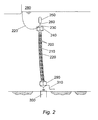
- Figure 2 shows a simplified multibore hybrid riser tower designed for a drill centre. It comprises two (in this example) production lines 200, a water injection line 210, buoyancy blocks 220, an Upper Riser Termination Assembly (URTA) 230 with its own self buoyancy 240, a buoyancy tank 250 connected to the URTA by a chain 260, jumpers 270 connecting the URTA 230 to a Floating Production Unit (FPU) 280.
- FPU Floating Production Unit
- LRTA Lower Riser Termination Assembly
- suction or gravity or other type of anchor 300 a rigid spool connection 310.
- This spool connection 310 can be made with a connector or an automatic tie-in system (such as the system known as MATIS (RTM) and described in WO03/040602 incorporated herein by reference). It should be noted that instead of the water injection line 210, the riser tower may comprise a gas injection line.
- MATIS MATIS
- conventional HRTs usually comprise a central structural core with a number of production and injection lines arranged therearound.
- the water injection line 210 doubles as a central core for the HRT structure, with the two production lines arranged either side, on the same plane, to give a flat cross-section.
- the inventors have identified that for a small isolated reservoir the minimum number of lines required are three, two production lines to allow pigging and one injection line to maintain pressure.
- the risers themselves may be fabricated onshore as horizontally sliding pipe-in-pipe incorporating annular gaslift lines, although separate gaslift lines can also be envisaged.
- the top connection of an annulus pipe-in-pipe can be performed by welding a bulkhead or by a mechanical connection.
- Figures 3a and 3b show, respectively, the riser tower in cross section and a section of the riser tower in perspective. This shows the two production lines 200, the water injection line/ central core 210, guide frame 320 and buoyancy foam blocks 220a, 220b.
- the guide frame 320 holds the three lines 200, 210 in place, in a line.
- a plurality of these guide frames 320 are comprised in the HRT, arranged at regular intervals along its length.
- buoyancy blocks 220a. 220b are arranged non-contiguously around the water injection line/ riser core.
- the riser assembly must be buoyant so that, in the event of loss of the HRT by the tugs towing it, it will not sink. Buoyancy of the HRT once installed is provided by the addition of the buoyancy 230 along the riser assemble and the buoyancy provided by the buoyancy element 250 at the top. Attaching buoyancy foam blocks to the risers themselves would reduce the compression in the core pipe but the hydrodynamic section would become very asymmetrical. Therefore, it is preferred for the foam blocks to be attached to the core pipe/ guide frame as shown.
- VIV Vortex Induced Vibration
- a conventional completely circular cross-section causes a wake, while the breaking up of this circular outline breaks the wake, resulting in a number of smaller eddy currents instead of one large one, and consequently reduced drag.
- the riser cross-section should still maintain a largely circular (or slight ovoid) profile, as there is no way of knowing the water current direction, so it is preferable that the structure should be as insensitive to direction as possible
- the distance between guide frames is governed by the amount of compression in the core pipe. Guiding devices are required between the guide frame and the riser.
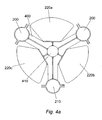
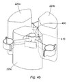
- Figures 4a and 4b show an alternative embodiment to that described above wherein the two production lines 200 and the single water injection line/ gas injection line 210 is arranged symmetrically around a structural core 410.
- guide frames 400 and buoyancy foam blocks 220a, 220b, 220c arranged non-contiguously around the core 410. It is possible in this embodiment for the structural core to be used as a line, should a further line be desired.
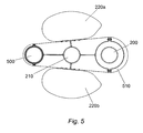
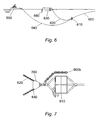
- FIG. 5 shows a variation of the embodiment depicted in figures 3a and 3b .
- this variation instead of two identical insulated production lines there is provided only one insulated production line 200 and one non-insulated service line 500.
- the water/gas injection line 210 acts as the structural core for the riser tower, and there are provided guide frames 510 at intervals along the length with buoyancy blocks 220a, 220b attached thereto.
- the service line is always filled with dead oil (not likely to form hydrates). Upon shutdown dead oil from the service line is pushed back into the production line.
- the hybrid riser is constructed onshore and then towed to its installation site were it is upended and installed. In order to be towed the riser is made neutrally buoyant (or within certain tolerances). Towing is done by at least two tugs, one leading and one at the rear.
- FIG. 6 shows (in part) a hybrid riser being towed to an installation site prior to being upended and installed. It shows the riser 600, and at what will be its top when installed, an upper riser installation assembly (URTA) 610. Attached to this via buoyancy tank tow line 620 is the main top buoyancy tank 630 floating on the sea surface. The URTA 610 is also attached to a trail tug 650 (the lead tug is not shown) about 650 metres behind the URTA via riser tow line 640. A section of the main permanent chain link 660a, attached to the buoyancy tank 630 and for making the permanent connection between this and the URTA 610, can also be seen, as yet unconnected. It should be noted that the buoyancy tank tow line 620 is actually attached to the top of the buoyancy tank 630, that is the buoyancy tank 630 is inverted compared to the riser 600 itself.
- URTA upper riser installation assembly
- Figure 7 shows in detail the rigging of the URTA 610. This shows a triplate with swivel 700 which connects the URTA 610 (and therefore the riser 600) to the buoyancy tank 630 and trail tug 650 by buoyancy tank tow line 620 and riser tow line 640 respectively. Also shown is the other section of the permanent chain link 660b attached to the top of the URTA 610.
- FIGs 8a and 8b show the trail tug and apparatus of Figure 6 during two steps of the installation method.
- This installation method is as follows: The buoyancy tank is moved back (possibly by a service vessel) and the trail tug 650 pays in the Riser tow line 640 and moves back 150 m towards the riser 600. The paying in of the tow rope causes the URTA 610 to rise towards the water surface. The buoyancy tank 630 is then rotated 90 degrees (again the service vessel will probably do this) to allow room for the permanent chain connection to be made.
- the slack buoyancy tank tow line 620 is now disconnected from the triplate swivel 700 and is then passed on to the trail tug 650. Therefore this line 620 is now connected between the trail tug 650 and the top of the buoyancy tank 630. This line 620 is then winched taut. The riser towing line 640 is then released. This situation is shown in Figure 4b . It can be seen that the tension now goes through the buoyancy tank towing line 620, buoyancy tank 620 and permanent chain 660. The triplate swivel 700 is then removed to give room to the permanent buoyancy tank shackle, and the permanent buoyancy tank shackle is secured. The upending process can now begin with the lead tug paying out the dead man anchor. The upending process is described in US06082391 and is incorporated herein by reference.
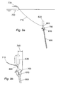
- FIGS 9a and 9b depicts a method for accessing the coil tubing unit for a Hybrid Riser Tower which has its buoyancy tank attached non-rigidly, for instance with a chain, as in this example.
- This shows the top part of the installed riser tower (which may have been installed by the method described above), and in particular the riser 600, URTA 610, buoyancy tank 630, permanent chain link 660, the coil tubing access 700, and a temporary line 710 from a winch 730 on the Floating Production, Storage and Offloading (FPSO) Vessel 720 to the bottom of the buoyancy tank 630.
- FPSO Floating Production, Storage and Offloading
- the method comprises attaching the temporary line 710 from the winch 730 on the FPSO 720 to the bottom of the buoyancy tank 630 and using the winch 730 to pull this line 710 causing the riser assembly to move off vertical. This provides the necessary clearance 740 for the coil tubing access.
- the inventors have recognised that, with the buoyancy tank 630 connected by a chain 660, the temporary line 710 should be attached to the bottom of the buoyancy tank 630. Should it be connected to the top of the buoyancy tank 630, the tank tends only to rotate, while connection to the URTA 610 means that the buoyancy tank 630 tends to remain directly above and still preventing the coil tubing access.
- buoyancy tank be towed with the riser to the installation site (although this is likely to be the lower cost option), the buoyancy tank may be transported separately and attached prior to upending.
Abstract
Description
- The present invention relates to hybrid riser towers and in particular hybrid riser towers for a drill centre.
- Hybrid Riser Towers are known and form part of the so-called hybrid riser, having an upper and/or lower portions ("jumpers") made of flexible conduit and suitable for deep and ultra-deep water field development.
US-A-6082391 (Stolt/Doris) andUS 4 098 333 proposes a particular Hybrid Riser Tower (HRT) consisting of an empty central core, supporting a bundle of riser pipes, some used for oil production some used for water and gas injection. This type of tower has been developed and deployed for example in the Girassol field off Angola. Insulating material in the form of syntactic foam blocks surrounds the core and the pipes and separates the hot and cold fluid conduits. Further background has been published in paper "Hybrid Riser Tower: from Functional Specification to Cost per Unit Length" by J-F Saint-Marcoux and M Rochereau, DOT XIII Rio de Janeiro, 18 October 2001. Updated versions of such risers have been proposed inWO 02/053869 A1 - One known solution is to use a number of Single Line Offset Risers (SLORs) which are essentially monobore HRTs. A problem with these structures is that for a drill centre (a cluster of wells), a large number of these structures are required, one for each production line, each injection line and each gas line. This means that each structure needs to be placed too close to adjacent structures resulting in the increased risk of each structure getting in the way of or interfering with others, due to wake shielding and wake instability .
- Another problem with all HRTs is vortex induced vibration (alternating shedding of trailing vortexes), which can lead to fatigue damage to drilling and production risers.
- The invention aims to address the above problems.
- In a first aspect of the invention there is provided a riser according to claim 1 comprising a plurality of conduits extending from the seabed toward the surface and having an upper end supported at a depth below the sea surface, wherein a first of said conduits acts as a central structural core, said other conduits being arranged around said first conduit.
- Said other conduits are preferably arranged substantially symmetrically around said first conduit.
- In a main embodiment said first conduit is a fluid injection line and said other conduits consist of production lines, Said riser preferably comprising two such production lines. At least one of said production lines may be thermally insulated.. In one embodiment both production lines are thermally insulated. Alternatively, only one of said production lines is thermally insulated, the uninsulated line being used as a service line. Said thermal insulation may be in the form of a pipe in pipe structure with the annular space used as a gas lift line. Said fluid injection line may be a water or gas injection line.
- Said riser further comprises buoyancy. Said buoyancy is in the form of blocks located at intervals along the length of the riser. Said blocks are arranged symmetrically around said first conduit to form a substantially circular cross-section. Said foam blocks are arranged non-contiguously around said first conduit.
- Said production lines may provide a pigging loop.
- In a further aspect of the invention there is provided a riser comprising three conduits arranged substantially symmetrically around a central core, said conduits extending from the seabed toward the surface and having an upper end supported at a depth below the sea surface, wherein a first of said conduits is a fluid injection line, said other conduits being production lines.
- Said production lines may provide a pigging loop.
- In a main embodiment said first conduit is a water injection line and said other conduits consist of production lines. Two such production lines may be provided. At least one of said production lines may be thermally insulated. In one embodiment both production lines are thermally insulated. Alternatively, only one of said production lines is thermally insulated, the uninsulated line being used as a service line. Said thermal insulation may be in the form of a pipe in pipe structure with the annular space used as a gas lift line.
- Said riser may further comprise buoyancy. Said buoyancy may be in the form of blocks located at intervals along the length of the riser. Said blocks may be arranged symmetrically around said first conduit to form a substantially circular cross-section. Said foam blocks are preferably arranged non-contiguously around said first conduit.
- Said riser may further comprise a plurality of guide frame elements arranged at intervals along the length of said riser, said frame elements guiding said conduits in place. Sliding devices between the risers and the guide frames may be included to allow sliding and dampen Vortex Induced Motion.
- Said structural core may also be used as a conduit, either as a production line, injection line or gas lift line.
- In a further aspect of the invention there is provided a riser comprising a plurality of conduits extending from the seabed toward the surface and having an upper end supported at a depth below the sea surface wherein said riser is provided with buoyancy along at least a part of its length, said buoyancy resulting in said riser having a generally circular cross-section, the circumference of which being non-contiguous.
- Generally circular in this case means that the general outline of the riser in cross section is circular (or slightly oval/ovoid) even though the outline is non-contiguous and may have considerable gaps in the circular shape.
- Said buoyancy may be in the form of blocks located at intervals along the length of the riser. Said blocks may be arranged symmetrically around said first conduit to form said largely circular cross-section. Said foam blocks are preferably arranged such that there are gaps between adjacent blocks to obtain said non-contiguous profile.
- A first of said conduits may act as a central structural core, said other conduits being arranged around said first conduit. Said other conduits are preferably arranged substantially symmetrically around said first conduit. In a main embodiment said first conduit is a fluid injection line and said other conduits consist of production lines. Said fluid injection line may be a water or gas injection line. Alternatively said riser may comprise three conduits arranged substantially symmetrically around a central core, wherein a first of said conduits is a fluid injection line, said other conduits being production lines.
- Two such production lines may be provided. At least one of said production lines may be thermally insulated.. In one embodiment both production lines are thermally insulated. Alternatively, only one of said production lines is thermally insulated, the uninsulated line being used as a service line. Said thermal insulation may be in the form of a pipe in pipe structure with the annular space used as a gas lift line.
- In a further not claimed aspect of the invention there is provided a method of installing a riser, said riser comprising a plurality of conduits extending from the seabed toward the surface and having an upper end supported at a depth below the sea surface by a buoyancy module, said riser being assembled at a place other than the installation site and transported thereto in a substantially horizontal configuration wherein said buoyancy module is attached to said riser by a non-rigid connection prior to said riser being upended to a substantially vertical working orientation.
- Said connection between the buoyancy module and the riser may be made at the installation site. Said non-rigid connection may be made using a chain. Said chain may be provided in two parts during transportation, with a first part connected to the riser (either directly or indirectly) and a second part connected to the buoyancy module (either directly or indirectly) while being transported. Said parts may be of approximately equal length. Said parts may each be in the region of 10m to 30m long. The two parts may be connected together on a service vessel. In order to provide room to make the connection, the buoyancy tank may first be rotated. Said rotation may be through approximately 90 degrees.
- Said buoyancy module may be towed to the installation site with the riser. Said buoyancy module may be towed behind said riser by connecting a towing line between the riser and the buoyancy module, independent of any other towing lines.
- In one embodiment, in which the riser and buoyancy module are transported together by a first, leading, vessel and second, trailing, vessel the method may comprise the following steps:
- the second vessel, connected by a first line to the top end of the riser during transportation, pays in said line and moves toward the riser,
- the Buoyancy module is rotated approximately 90 degrees,
- the permanent connection between riser and buoyancy module is made on a service vessel;
- a second line, which connected the top of the buoyancy module to the top of the riser during transportation, is disconnected from said riser and passed to said second vessel;
- Said first line is disconnected,
- The riser upending process begins.
- Reference to "top" and "bottom" above is to be understood to mean the top and bottom of the item referred to when it is installed.
- In a further aspect of the invention there is provided a method of accessing a coil tubing unit located substantially at the top of a riser structure, said riser structure comprising a plurality of conduits extending from the seabed toward the surface and having an upper end supported at a depth below the sea surface by a buoyancy module, wherein said method comprises attaching a line to a point substantially near the top of said riser, and exerting a force on said line to pull said riser, or a top portion thereof, from its normal substantially vertical configuration to a configuration off vertical.
- The riser's normal substantially vertical configuration should be understood to cover orientations off true vertical, yet vertical in comparison to other riser systems.
- Said buoyancy module may be attached to said riser (directly or indirectly) by means of a non-rigid connection such as a chain. Said line is preferably attached to a lower portion of said buoyancy module. The tension on said line may therefore also cause said buoyancy module to be moved a distance laterally away from the vertical axis of said riser, thereby allowing access to the coil tubing unit from directly above.
- Said tension may be exerted on said line by means of a winch or similar device. Said winch may be located on a Floating Production, Storage and Offloading (FPSO) Vessel.
- Embodiments of the invention will now be described, by way of example only, by reference to the accompanying drawings, in which:
-
Fig. 1 shows a known type of riser structure in an offshore oil production system; -
Fig. 2 shows a riser structure according to an embodiment of the invention; -
Figs. 3a and 3b show, respectively, the riser structure ofFig. 2 in cross section and a section of the riser tower in perspective; -
Figs. 4a and4b show, respectively, an alternative riser structure in cross section and a section of the alternative riser tower in perspective; -
Fig 5 shows an alternative riser structure in cross-section; -
Fig. 6 shows a riser structure with buoyancy tank being towed to an installation site, -
Fig. 7 shows in detail the towing connection assembly used inFig. 6 -
Figs. 8a and 8b depict two steps in the installation method according to an embodiment of the invention; and -
Figs. 9a and 9b depict a method for accessing the coil tubing according to a second embodiment of the invention. -
Figure 1 illustrates a floatingoffshore structure 100 fed byriser bundles 110, which are supported by subsea buoys 115.Spurs 120 extend from the bottom of the riser bundle to the various well heads 130. The floating structure is kept in place by mooring lines (not shown), attached to anchors (not shown) on the seabed. The example shown is of a type known generally from the Girassol development, mentioned in the introduction above. - Each riser bundle is supported by the upward force provided by its associated buoy 115. Flexible jumpers 135 are then used between the buoys and the floating
structure 100. The tension in the riser bundles is a result of the net effect of the buoyancy combined with the ultimate weight of the structure and risers in the seawater. The skilled person will appreciate that the bundle may be a few metres in diameter, but is a very slender structure in view of its length (height) of for example 500m, or even 1km or more. The structure must be protected from excessive bending and the tension in the bundle is of assistance in this regard. - Hybrid Riser Towers (HRTs), such as those described above, have been developed as monobore structures or as structures comprising a number, in the region of six to twelve, of risers arranged around a central structural core.
- It is normal for deepwater developments to be phased and are often built around a drill centre. A drill centre is usually of two piggable production lines (at least one being thermally insulated) and an injection line.
-
Figure 2 shows a simplified multibore hybrid riser tower designed for a drill centre. It comprises two (in this example)production lines 200, awater injection line 210, buoyancy blocks 220, an Upper Riser Termination Assembly (URTA) 230 with itsown self buoyancy 240, abuoyancy tank 250 connected to the URTA by achain 260, jumpers 270 connecting theURTA 230 to a Floating Production Unit (FPU) 280. At the lower end there is a Lower Riser Termination Assembly (LRTA) 290, a suction or gravity or other type ofanchor 300, and arigid spool connection 310. Thisspool connection 310 can be made with a connector or an automatic tie-in system (such as the system known as MATIS (RTM) and described inWO03/040602 water injection line 210, the riser tower may comprise a gas injection line. - As mentioned previously, conventional HRTs usually comprise a central structural core with a number of production and injection lines arranged therearound. In this structure. however, the
water injection line 210 doubles as a central core for the HRT structure, with the two production lines arranged either side, on the same plane, to give a flat cross-section. - The inventors have identified that for a small isolated reservoir the minimum number of lines required are three, two production lines to allow pigging and one injection line to maintain pressure.
- The risers themselves may be fabricated onshore as horizontally sliding pipe-in-pipe incorporating annular gaslift lines, although separate gaslift lines can also be envisaged. The top connection of an annulus pipe-in-pipe can be performed by welding a bulkhead or by a mechanical connection.
-
Figures 3a and 3b show, respectively, the riser tower in cross section and a section of the riser tower in perspective. This shows the twoproduction lines 200, the water injection line/central core 210,guide frame 320 andbuoyancy foam blocks guide frame 320 holds the threelines - It can also be seen that the buoyancy blocks 220a. 220b are arranged non-contiguously around the water injection line/ riser core. For an onshore-assembled HRT, the riser assembly must be buoyant so that, in the event of loss of the HRT by the tugs towing it, it will not sink. Buoyancy of the HRT once installed is provided by the addition of the
buoyancy 230 along the riser assemble and the buoyancy provided by thebuoyancy element 250 at the top. Attaching buoyancy foam blocks to the risers themselves would reduce the compression in the core pipe but the hydrodynamic section would become very asymmetrical. Therefore, it is preferred for the foam blocks to be attached to the core pipe/ guide frame as shown. - The fact that the foam blocks are arranged non-contiguously around the HRT (as well as being applied non-contiguously along its length) minimises the occurrence of Vortex Induced Vibration (VIV) in the riser tower. A conventional completely circular cross-section causes a wake, while the breaking up of this circular outline breaks the wake, resulting in a number of smaller eddy currents instead of one large one, and consequently reduced drag. The riser cross-section should still maintain a largely circular (or slight ovoid) profile, as there is no way of knowing the water current direction, so it is preferable that the structure should be as insensitive to direction as possible
- The distance between guide frames is governed by the amount of compression in the core pipe. Guiding devices are required between the guide frame and the riser.
-
Figures 4a and4b show an alternative embodiment to that described above wherein the twoproduction lines 200 and the single water injection line/gas injection line 210 is arranged symmetrically around astructural core 410. As before there areguide frames 400 andbuoyancy foam blocks core 410. It is possible in this embodiment for the structural core to be used as a line, should a further line be desired. -
Figure 5 shows a variation of the embodiment depicted infigures 3a and 3b . In this variation instead of two identical insulated production lines there is provided only oneinsulated production line 200 and onenon-insulated service line 500. As before, the water/gas injection line 210 acts as the structural core for the riser tower, and there are provided guide frames 510 at intervals along the length withbuoyancy blocks - It should be noted that the hybrid riser is constructed onshore and then towed to its installation site were it is upended and installed. In order to be towed the riser is made neutrally buoyant (or within certain tolerances). Towing is done by at least two tugs, one leading and one at the rear.
-
Figure 6 shows (in part) a hybrid riser being towed to an installation site prior to being upended and installed. It shows theriser 600, and at what will be its top when installed, an upper riser installation assembly (URTA) 610. Attached to this via buoyancytank tow line 620 is the maintop buoyancy tank 630 floating on the sea surface. TheURTA 610 is also attached to a trail tug 650 (the lead tug is not shown) about 650 metres behind the URTA viariser tow line 640. A section of the main permanent chain link 660a, attached to thebuoyancy tank 630 and for making the permanent connection between this and theURTA 610, can also be seen, as yet unconnected. It should be noted that the buoyancytank tow line 620 is actually attached to the top of thebuoyancy tank 630, that is thebuoyancy tank 630 is inverted compared to theriser 600 itself. -
Figure 7 shows in detail the rigging of theURTA 610. This shows a triplate withswivel 700 which connects the URTA 610 (and therefore the riser 600) to thebuoyancy tank 630 andtrail tug 650 by buoyancytank tow line 620 andriser tow line 640 respectively. Also shown is the other section of thepermanent chain link 660b attached to the top of theURTA 610. - By using a chain to connect the buoyancy tank to the riser (instead of, for example a flexjoint) and by making the chain link long enough (say each section 630a, 630b being about 20 metres in length) it becomes possible to attach the
buoyancy tank 230 to theriser 600 by joining these two sections 630a, 630b together at the installation site prior to upending. This dispenses with the need to have a heavy installation vessel with crane to hold and install the buoyancy tank when upended. Only service vessels are required. It also allows the possibility of towing the buoyancy tank with the riser to the installation site thus reducing cost. Furthermore, the use of a chain instead of a rigid connection dispenses with the need for a taper joint. -
Figures 8a and 8b show the trail tug and apparatus ofFigure 6 during two steps of the installation method. This installation method is as follows: The buoyancy tank is moved back (possibly by a service vessel) and thetrail tug 650 pays in theRiser tow line 640 and moves back 150 m towards theriser 600. The paying in of the tow rope causes theURTA 610 to rise towards the water surface. Thebuoyancy tank 630 is then rotated 90 degrees (again the service vessel will probably do this) to allow room for the permanent chain connection to be made. - With the
buoyancy tank 630 rotated, the service vessels pays in the 60m permanent chain section 660a from thebuoyancy tank 630, and the 60mpermanent chain section 660b on theURTA 610. The permanent chain link between thebuoyancy tank 630 and the URTA 610 (and therefore the riser 600) is made on the shark jaws of the service vessel. The resulting situation is shown inFigure 4a . This shows thebuoyancy tank 630 at 90 degrees with thepermanent chain connection 660 in place. The trail tug 650 (now about 100m from the URTA 610) is still connected to theURTA 610 byriser tow line 640. The buoyancytank tow line 620 is still connected between thebuoyancy tank 630 and theURTA 610 and is now slack. - The slack buoyancy
tank tow line 620 is now disconnected from thetriplate swivel 700 and is then passed on to thetrail tug 650. Therefore thisline 620 is now connected between thetrail tug 650 and the top of thebuoyancy tank 630. Thisline 620 is then winched taut. Theriser towing line 640 is then released. This situation is shown inFigure 4b . It can be seen that the tension now goes through the buoyancytank towing line 620,buoyancy tank 620 andpermanent chain 660. Thetriplate swivel 700 is then removed to give room to the permanent buoyancy tank shackle, and the permanent buoyancy tank shackle is secured. The upending process can now begin with the lead tug paying out the dead man anchor. The upending process is described inUS06082391 and is incorporated herein by reference. - One issue with the Hybrid Riser Tower as described (with chain connection to the buoyancy tank) is the coil tubing access. This was previously done by having access to the coil tubing unit to be from directly vertically above the URTA. In this case the buoyancy tank was rigidly connected with a taper joint. However access from vertically above is not possible with the buoyancy tank attached to a chain also directly vertically above the URTA.
-
Figures 9a and 9b depicts a method for accessing the coil tubing unit for a Hybrid Riser Tower which has its buoyancy tank attached non-rigidly, for instance with a chain, as in this example. This shows the top part of the installed riser tower (which may have been installed by the method described above), and in particular theriser 600,URTA 610,buoyancy tank 630,permanent chain link 660, thecoil tubing access 700, and atemporary line 710 from awinch 730 on the Floating Production, Storage and Offloading (FPSO)Vessel 720 to the bottom of thebuoyancy tank 630. - The method comprises attaching the
temporary line 710 from thewinch 730 on theFPSO 720 to the bottom of thebuoyancy tank 630 and using thewinch 730 to pull thisline 710 causing the riser assembly to move off vertical. This provides thenecessary clearance 740 for the coil tubing access. - The inventors have recognised that, with the
buoyancy tank 630 connected by achain 660, thetemporary line 710 should be attached to the bottom of thebuoyancy tank 630. Should it be connected to the top of thebuoyancy tank 630, the tank tends only to rotate, while connection to theURTA 610 means that thebuoyancy tank 630 tends to remain directly above and still preventing the coil tubing access. - The above embodiments are for illustration only and other embodiments and variations are possible. For example it is not essential that the buoyancy tank be towed with the riser to the installation site (although this is likely to be the lower cost option), the buoyancy tank may be transported separately and attached prior to upending.
Claims (12)
- A riser comprising a plurality of conduits (200, 210) extending in use from the seabed toward the surface and having an upper end adapted to be supported in use at a depth below the sea surface wherein said riser is provided with buoyancy along at least a part of its length, wherein said buoyancy is in the form of blocks (220) located at intervals along the length of the riser, wherein said blocks (220) are arranged symmetrically around a central structural core (210, 410) to form a substantially circular cross-section, characterized in that said blocks (220) are arranged non-contiguously around said central structural core (210, 410).
- A riser as claimed in claim 1 wherein the central structural core (210) comprises a first conduit of said plurality of conduits, wherein other conduits are arranged around said first conduit.
- A riser as claimed in claim 2 wherein said other conduits are arranged substantially symmetrically around said first conduit.
- A riser as claimed in claim 2 or claim 3 wherein said first conduit is a fluid injection line (210) and said other conduits consist of production lines (200).
- A riser as claimed in claim 1 wherein said riser comprises three conduits arranged substantially symmetrically around the central structural core (410), wherein one of the three conduit is a fluid injection line (210), said other conduits being production lines (200).
- A riser as claimed in claims 4 or claim 5 wherein said fluid injection line is a water injection line.
- A riser as claimed in claim 4 or claim 5 wherein said fluid injection line is a gas injection line.
- A riser as claimed in any of claims 4 to 7 wherein two such production lines are provided.
- A riser as claimed in claim 8 wherein at least one of said production lines is thermally insulated.
- A riser as claimed in claim 9 wherein both production lines are thermally insulated.
- A riser as claimed in claim 9 wherein one of said production lines is thermally insulated, the uninsulated line being used as a service line.
- A riser as claimed in any of claims 9 to 11 wherein said thermal insulation is in the form of a pipe in pipe structure with the annular space used as a gas lift line.
Applications Claiming Priority (4)
| Application Number | Priority Date | Filing Date | Title |
|---|---|---|---|
| US85757206P | 2006-11-08 | 2006-11-08 | |
| GBGB0704670.9A GB0704670D0 (en) | 2006-11-08 | 2007-03-10 | Hybrid tower and methods of installing same |
| EP07824887A EP2079633B1 (en) | 2006-11-08 | 2007-11-06 | Method of installing hybrid riser tower |
| EP09163664A EP2130758B1 (en) | 2006-11-08 | 2007-11-06 | Method of accessing a coil tubing unit |
Related Parent Applications (2)
| Application Number | Title | Priority Date | Filing Date |
|---|---|---|---|
| EP07824887.9 Division | 2007-11-06 | ||
| EP09163664.7 Division | 2009-06-24 |
Publications (2)
| Publication Number | Publication Date |
|---|---|
| EP2474468A1 EP2474468A1 (en) | 2012-07-11 |
| EP2474468B1 true EP2474468B1 (en) | 2013-06-19 |
Family
ID=39144588
Family Applications (4)
| Application Number | Title | Priority Date | Filing Date |
|---|---|---|---|
| EP09163664A Active EP2130758B1 (en) | 2006-11-08 | 2007-11-06 | Method of accessing a coil tubing unit |
| EP12161917.5A Active EP2474468B1 (en) | 2006-11-08 | 2007-11-06 | Hybrid riser tower |
| EP07824887A Active EP2079633B1 (en) | 2006-11-08 | 2007-11-06 | Method of installing hybrid riser tower |
| EP12161905.0A Active EP2818399B1 (en) | 2006-11-08 | 2007-11-06 | Hybrid riser tower |
Family Applications Before (1)
| Application Number | Title | Priority Date | Filing Date |
|---|---|---|---|
| EP09163664A Active EP2130758B1 (en) | 2006-11-08 | 2007-11-06 | Method of accessing a coil tubing unit |
Family Applications After (2)
| Application Number | Title | Priority Date | Filing Date |
|---|---|---|---|
| EP07824887A Active EP2079633B1 (en) | 2006-11-08 | 2007-11-06 | Method of installing hybrid riser tower |
| EP12161905.0A Active EP2818399B1 (en) | 2006-11-08 | 2007-11-06 | Hybrid riser tower |
Country Status (9)
| Country | Link |
|---|---|
| US (1) | US8186912B2 (en) |
| EP (4) | EP2130758B1 (en) |
| AT (1) | ATE499282T1 (en) |
| AU (1) | AU2007319011B2 (en) |
| BR (3) | BR122018073554B1 (en) |
| DE (1) | DE602007012744D1 (en) |
| GB (1) | GB0704670D0 (en) |
| NO (2) | NO344207B1 (en) |
| WO (1) | WO2008056185A2 (en) |
Families Citing this family (22)
| Publication number | Priority date | Publication date | Assignee | Title |
|---|---|---|---|---|
| GB0810355D0 (en) * | 2008-06-06 | 2008-07-09 | Acergy France Sa | Methods and apparatus for hydrocarbon recovery |
| FR2932839B1 (en) | 2008-06-23 | 2010-08-20 | Technip France | UNDERWATER TRANSPORTATION FACILITY FOR HYDROCARBONS. |
| US20100059230A1 (en) * | 2008-09-05 | 2010-03-11 | Harold Brian Skeels | Coil tubing guide |
| GB0900097D0 (en) * | 2009-01-07 | 2009-02-11 | Acergy Us Inc | Improvements in hybrid riser towers and fabrication thereof |
| GB0900101D0 (en) * | 2009-01-07 | 2009-02-11 | Acergy Us Inc | Methods and associated apparatus of constructing and installing rigid riser structures |
| FR2942497B1 (en) | 2009-02-26 | 2013-04-26 | Saipem Sa | MULTI-RISER HYBRID TILT-TYPE FLAT-SURFACE LINK INSTALLATION COMPRISING SLIDING FLOATING MODULES |
| WO2011050064A1 (en) | 2009-10-21 | 2011-04-28 | Fluor Technologies Corporation | Hybrid buoyed and stayed towers and risers for deepwater |
| GB2475108A (en) * | 2009-11-05 | 2011-05-11 | Acergy Us Inc | Methods of constructing and installing rigid riser structures and associated apparatus |
| US8821070B2 (en) * | 2010-02-10 | 2014-09-02 | Heerema Marine Contractors Nederland Se | Method for constructing a riser assembly from a vessel and on a seabed |
| FR2960208B1 (en) | 2010-05-20 | 2012-08-10 | Saipem Sa | SURFACE BONDING SYSTEM COMPRISING A FLEXIBLE DRIVING GUIDE STRUCTURE |
| WO2011150363A1 (en) * | 2010-05-28 | 2011-12-01 | Weatherford/Lamb, Inc. | Deepwater completion installation and intervention system |
| US20120043052A1 (en) * | 2010-07-23 | 2012-02-23 | Heat-Line Corporation | Geothermal Energy Transfer System |
| US9334695B2 (en) * | 2011-04-18 | 2016-05-10 | Magma Global Limited | Hybrid riser system |
| GB2500102B (en) * | 2012-03-05 | 2014-01-29 | Acergy France Sa | Buoyancy arrangements for hybrid riser towers |
| US10378331B2 (en) * | 2012-05-30 | 2019-08-13 | Onesubsea Ip Uk Limited | Monitoring integrity of a riser pipe network |
| WO2015168432A1 (en) * | 2014-04-30 | 2015-11-05 | Seahorse Equipment Corp | Bundled, articulated riser system for fpso vessel |
| US20180266194A1 (en) * | 2015-12-21 | 2018-09-20 | Halliburton Energy Services, Inc. | Method and system for deployment of tubing strings for riser-less applications |
| KR101696156B1 (en) * | 2016-07-27 | 2017-01-12 | 김정현 | Flexible riser system |
| GB2559810B (en) | 2017-02-21 | 2021-01-06 | Acergy France SAS | Fabrication of pipe bundles offshore |
| BR102018076868A2 (en) * | 2018-12-21 | 2020-07-07 | Odebrecht Óleo E Gás S.A. | guide system on a hybrid lift tower, and hybrid lift tower |
| NO20201397A1 (en) * | 2020-12-18 | 2022-06-20 | Subsea 7 Norway As | Storage of fluids underwater |
| GB2602115B (en) | 2020-12-18 | 2023-07-12 | Subsea 7 Norway As | Storage of fluids underwater |
Family Cites Families (38)
| Publication number | Priority date | Publication date | Assignee | Title |
|---|---|---|---|---|
| US3517110A (en) * | 1968-04-01 | 1970-06-23 | North American Rockwell | Flexible underwater riser containing electrical conductors and material conduits |
| FR2029884A5 (en) * | 1969-01-30 | 1970-10-23 | Liautaud Jean | Production storage and bunkering assembly - for an underwater petroleum field |
| NL152649B (en) | 1970-01-28 | 1977-03-15 | Shell Int Research | PIPELINE OR PIPELINE SECTION FOR THE TRANSPORT OF A FLUIDUM IN CRYOGENIC TEMPERATURES, FOR EXAMPLE LIQUID NATURAL GAS. |
| AR192712A1 (en) * | 1970-07-08 | 1973-03-14 | Snam Progetti | ANCHORING DEVICE FOR MOORING BUOYS |
| DE2543293C3 (en) * | 1975-09-27 | 1978-03-16 | Thyssen Industrie Ag, 4300 Essen | Underwater drilling device |
| US4098333A (en) * | 1977-02-24 | 1978-07-04 | Compagnie Francaise Des Petroles | Marine production riser system |
| FR2391900A1 (en) * | 1977-05-26 | 1978-12-22 | Inst Francais Du Petrole | METHOD FOR IMMERSING A NEGATIVE BUOYANCY DEVICE |
| FR2510713A1 (en) | 1981-07-31 | 1983-02-04 | Vallourec | PREFABRICATED TUBE ELEMENT FOR FLUID TRANSPORT PIPES AT TEMPERATURE DIFFERENT FROM THE AMBIENT |
| SE8300252L (en) | 1983-01-19 | 1984-07-20 | Dansk Rorind | SET TO SHARP TWO FORISOLATED PIPES AND A SHARP SHELET TO BE USED IN APPLICATION OF THESE SETS |
| US4645467A (en) * | 1984-04-24 | 1987-02-24 | Amtel, Inc. | Detachable mooring and cargo transfer system |
| US4673313A (en) | 1985-04-11 | 1987-06-16 | Mobil Oil Corporation | Marine production riser and method for installing same |
| DE3934253A1 (en) | 1988-10-14 | 1990-04-19 | Architektur Bauwesen Hochschul | Ceramic and glass or glass pipe section - has casing and inner and outer tie pieces, with tubular sleeve and pipe straps |
| NO953217L (en) * | 1995-08-16 | 1997-02-17 | Aker Eng As | Method and arrangement of pipe bundles |
| FR2751721B1 (en) | 1996-07-26 | 1998-09-11 | Itp | METHOD FOR ASSEMBLING PIPES BY ASSEMBLY AT SEA OF SUCCESSIVE PIPES, AND PIPES FOR IMPLEMENTING THIS PROCESS |
| FR2768457B1 (en) | 1997-09-12 | 2000-05-05 | Stolt Comex Seaway | DEVICE FOR UNDERWATER TRANSPORT OF PETROLEUM PRODUCTS WITH A COLUMN |
| NO981701D0 (en) | 1998-04-16 | 1998-04-16 | Kvaerner Oilfield Prod As | Compound hybrid rises year |
| US6004074A (en) * | 1998-08-11 | 1999-12-21 | Mobil Oil Corporation | Marine riser having variable buoyancy |
| GB2346188A (en) * | 1999-01-29 | 2000-08-02 | 2H Offshore Engineering Limite | Concentric offset riser |
| US6155748A (en) * | 1999-03-11 | 2000-12-05 | Riser Systems Technologies | Deep water riser flotation apparatus |
| NO994094D0 (en) * | 1999-08-24 | 1999-08-24 | Aker Riser Systems As | riser |
| FR2809136B1 (en) | 2000-05-19 | 2002-11-08 | Saibos Construcoes Maritimas L | BASE-SURFACE CONNECTION INSTALLATION FOR SUBSEA PIPE, CONNECTION DEVICE BETWEEN A FLOAT AND A RISER, AND INTERVENTION METHOD IN SAID RISER |
| EP1305206B1 (en) * | 2000-08-01 | 2004-11-10 | Single Buoy Moorings Inc. | Method and structure for connecting a floating structure with rope anchor lines to the seabed |
| WO2002012776A1 (en) * | 2000-08-03 | 2002-02-14 | Stolt Offshore Sa | Thermally insulated pipeline bundle |
| WO2002063128A1 (en) | 2001-01-08 | 2002-08-15 | Stolt Offshore Sa | Marine riser tower |
| US7104330B2 (en) * | 2001-01-08 | 2006-09-12 | Stolt Offshore S.A. | Marine riser tower |
| US6948884B2 (en) * | 2001-03-14 | 2005-09-27 | Technip France | Vortex-induced vibration reduction device for fluid immersed cylinders |
| FR2825116B1 (en) * | 2001-05-25 | 2003-12-05 | Inst Francais Du Petrole | METHOD FOR DIMENSIONING A DRILLING RISER |
| GB2376728A (en) | 2001-06-20 | 2002-12-24 | Corus Uk Ltd | A method of manufacturing a double-walled pipe structure |
| GB2380747B (en) * | 2001-10-10 | 2005-12-21 | Rockwater Ltd | A riser and method of installing same |
| US7445404B2 (en) * | 2001-11-06 | 2008-11-04 | Acergy Uk Limited | Remote bolted flange connection apparatus and methods of operation thereof |
| GB0227851D0 (en) | 2002-11-29 | 2003-01-08 | Stolt Offshore Sa | Subsea structure and methods of construction and installation thereof |
| US7070361B2 (en) * | 2003-03-06 | 2006-07-04 | Shell Oil Company | Apparatus and methods for providing VIV suppression to a riser system comprising umbilical elements |
| FR2852677B1 (en) * | 2003-03-18 | 2006-01-06 | Saipem Sa | DEVICE FOR HEATING AND THERMALLY INSULATING AT LEAST ONE UNDERWATER DRIVING |
| GB0409361D0 (en) * | 2004-04-27 | 2004-06-02 | Stolt Offshore Sa | Marine riser tower |
| US7191836B2 (en) * | 2004-08-02 | 2007-03-20 | Kellogg Brown & Root Llc | Dry tree subsea well communications apparatus and method using variable tension large offset risers |
| GB2419171A (en) | 2004-10-14 | 2006-04-19 | Crp Group Ltd | Insulated pipe assembly |
| GB0512471D0 (en) | 2005-06-18 | 2005-07-27 | Stolt Offshore Sa | Hybrid riser tower and methods of installation thereof |
| US20070044972A1 (en) * | 2005-09-01 | 2007-03-01 | Roveri Francisco E | Self-supported riser system and method of installing same |
-
2007
- 2007-03-10 GB GBGB0704670.9A patent/GB0704670D0/en not_active Ceased
- 2007-11-06 EP EP09163664A patent/EP2130758B1/en active Active
- 2007-11-06 BR BR122018073554A patent/BR122018073554B1/en active IP Right Grant
- 2007-11-06 AU AU2007319011A patent/AU2007319011B2/en active Active
- 2007-11-06 AT AT07824887T patent/ATE499282T1/en not_active IP Right Cessation
- 2007-11-06 EP EP12161917.5A patent/EP2474468B1/en active Active
- 2007-11-06 WO PCT/GB2007/050675 patent/WO2008056185A2/en active Application Filing
- 2007-11-06 BR BRPI0718827-7A patent/BRPI0718827B1/en active IP Right Grant
- 2007-11-06 EP EP07824887A patent/EP2079633B1/en active Active
- 2007-11-06 BR BR122018073569A patent/BR122018073569B1/en active IP Right Grant
- 2007-11-06 EP EP12161905.0A patent/EP2818399B1/en active Active
- 2007-11-06 US US12/513,840 patent/US8186912B2/en active Active
- 2007-11-06 DE DE602007012744T patent/DE602007012744D1/en active Active
-
2009
- 2009-06-08 NO NO20092183A patent/NO344207B1/en unknown
-
2019
- 2019-06-20 NO NO20190762A patent/NO345042B1/en unknown
Also Published As
| Publication number | Publication date |
|---|---|
| BRPI0718827B1 (en) | 2019-06-18 |
| WO2008056185A2 (en) | 2008-05-15 |
| EP2818399A1 (en) | 2014-12-31 |
| EP2130758A2 (en) | 2009-12-09 |
| BR122018073554B1 (en) | 2019-11-26 |
| AU2007319011A1 (en) | 2008-05-15 |
| EP2079633A2 (en) | 2009-07-22 |
| EP2130758B1 (en) | 2013-01-23 |
| US20100172699A1 (en) | 2010-07-08 |
| NO20092183L (en) | 2009-06-08 |
| ATE499282T1 (en) | 2011-03-15 |
| WO2008056185A3 (en) | 2009-02-19 |
| EP2130758A3 (en) | 2010-07-07 |
| NO20190762A1 (en) | 2009-06-08 |
| DE602007012744D1 (en) | 2011-04-07 |
| US8186912B2 (en) | 2012-05-29 |
| AU2007319011B2 (en) | 2013-06-13 |
| NO344207B1 (en) | 2019-10-14 |
| GB0704670D0 (en) | 2007-04-18 |
| EP2474468A1 (en) | 2012-07-11 |
| EP2818399B1 (en) | 2016-03-16 |
| BR122018073569B1 (en) | 2019-11-26 |
| NO345042B1 (en) | 2020-09-07 |
| EP2079633B1 (en) | 2011-02-23 |
| BRPI0718827A2 (en) | 2014-02-04 |
Similar Documents
| Publication | Publication Date | Title |
|---|---|---|
| EP2474468B1 (en) | Hybrid riser tower | |
| US6415828B1 (en) | Dual buoy single point mooring and fluid transfer system | |
| US8998539B2 (en) | Hybrid riser tower and methods of installing same | |
| EP2504517B1 (en) | Riser configuration | |
| US9562399B2 (en) | Bundled, articulated riser system for FPSO vessel | |
| US20100129161A1 (en) | Hybrid riser systems and methods | |
| JP2020514175A (en) | Steel Catenary Riser Top Interface | |
| US8282317B2 (en) | Subsea structure and methods of construction and installation thereof | |
| US7713104B2 (en) | Apparatus and method for connection and disconnection of a marine riser | |
| AU2013216661B2 (en) | Hybrid riser tower | |
| US20070003374A1 (en) | Subsea structure and methods of construction and installation thereof | |
| Seguin et al. | Riser Solutions for Turret-Moored FPSOs With or Without Disconnectable Turret | |
| GB2558305B (en) | Controlling buoyancy when towing, lowering and raising submerged structures | |
| US20120043090A1 (en) | Improved subsea riser system | |
| WO2011018713A2 (en) | Marine riser apparatus and method of installation thereof |
Legal Events
| Date | Code | Title | Description |
|---|---|---|---|
| PUAI | Public reference made under article 153(3) epc to a published international application that has entered the european phase |
Free format text: ORIGINAL CODE: 0009012 |
|
| AC | Divisional application: reference to earlier application |
Ref document number: 2079633 Country of ref document: EP Kind code of ref document: P Ref document number: 2130758 Country of ref document: EP Kind code of ref document: P |
|
| AK | Designated contracting states |
Kind code of ref document: A1 Designated state(s): AT BE BG CH CY CZ DE DK EE ES FI FR GB GR HU IE IS IT LI LT LU LV MC MT NL PL PT RO SE SI SK TR |
|
| RIN1 | Information on inventor provided before grant (corrected) |
Inventor name: DE-ROUX, GREGOIRE FRANCOIS Inventor name: SAINT-MARCOUX, JEAN-FRANCOIS Inventor name: BRANCHUT, JEAN-PIERRE |
|
| 17P | Request for examination filed |
Effective date: 20121120 |
|
| RIC1 | Information provided on ipc code assigned before grant |
Ipc: E21B 17/01 20060101ALI20121217BHEP Ipc: B63B 35/44 20060101AFI20121217BHEP |
|
| GRAP | Despatch of communication of intention to grant a patent |
Free format text: ORIGINAL CODE: EPIDOSNIGR1 |
|
| GRAS | Grant fee paid |
Free format text: ORIGINAL CODE: EPIDOSNIGR3 |
|
| GRAA | (expected) grant |
Free format text: ORIGINAL CODE: 0009210 |
|
| AC | Divisional application: reference to earlier application |
Ref document number: 2079633 Country of ref document: EP Kind code of ref document: P Ref document number: 2130758 Country of ref document: EP Kind code of ref document: P |
|
| AK | Designated contracting states |
Kind code of ref document: B1 Designated state(s): AT BE BG CH CY CZ DE DK EE ES FI FR GB GR HU IE IS IT LI LT LU LV MC MT NL PL PT RO SE SI SK TR |
|
| REG | Reference to a national code |
Ref country code: GB Ref legal event code: FG4D |
|
| REG | Reference to a national code |
Ref country code: CH Ref legal event code: EP |
|
| REG | Reference to a national code |
Ref country code: AT Ref legal event code: REF Ref document number: 617494 Country of ref document: AT Kind code of ref document: T Effective date: 20130715 |
|
| REG | Reference to a national code |
Ref country code: IE Ref legal event code: FG4D |
|
| REG | Reference to a national code |
Ref country code: DE Ref legal event code: R096 Ref document number: 602007031218 Country of ref document: DE Effective date: 20130814 |
|
| PG25 | Lapsed in a contracting state [announced via postgrant information from national office to epo] |
Ref country code: FI Free format text: LAPSE BECAUSE OF FAILURE TO SUBMIT A TRANSLATION OF THE DESCRIPTION OR TO PAY THE FEE WITHIN THE PRESCRIBED TIME-LIMIT Effective date: 20130619 Ref country code: SE Free format text: LAPSE BECAUSE OF FAILURE TO SUBMIT A TRANSLATION OF THE DESCRIPTION OR TO PAY THE FEE WITHIN THE PRESCRIBED TIME-LIMIT Effective date: 20130619 Ref country code: LT Free format text: LAPSE BECAUSE OF FAILURE TO SUBMIT A TRANSLATION OF THE DESCRIPTION OR TO PAY THE FEE WITHIN THE PRESCRIBED TIME-LIMIT Effective date: 20130619 Ref country code: GR Free format text: LAPSE BECAUSE OF FAILURE TO SUBMIT A TRANSLATION OF THE DESCRIPTION OR TO PAY THE FEE WITHIN THE PRESCRIBED TIME-LIMIT Effective date: 20130920 Ref country code: SI Free format text: LAPSE BECAUSE OF FAILURE TO SUBMIT A TRANSLATION OF THE DESCRIPTION OR TO PAY THE FEE WITHIN THE PRESCRIBED TIME-LIMIT Effective date: 20130619 Ref country code: ES Free format text: LAPSE BECAUSE OF FAILURE TO SUBMIT A TRANSLATION OF THE DESCRIPTION OR TO PAY THE FEE WITHIN THE PRESCRIBED TIME-LIMIT Effective date: 20130930 |
|
| REG | Reference to a national code |
Ref country code: AT Ref legal event code: MK05 Ref document number: 617494 Country of ref document: AT Kind code of ref document: T Effective date: 20130619 |
|
| REG | Reference to a national code |
Ref country code: LT Ref legal event code: MG4D |
|
| PG25 | Lapsed in a contracting state [announced via postgrant information from national office to epo] |
Ref country code: BG Free format text: LAPSE BECAUSE OF FAILURE TO SUBMIT A TRANSLATION OF THE DESCRIPTION OR TO PAY THE FEE WITHIN THE PRESCRIBED TIME-LIMIT Effective date: 20130919 |
|
| REG | Reference to a national code |
Ref country code: NL Ref legal event code: VDEP Effective date: 20130619 |
|
| PG25 | Lapsed in a contracting state [announced via postgrant information from national office to epo] |
Ref country code: LV Free format text: LAPSE BECAUSE OF FAILURE TO SUBMIT A TRANSLATION OF THE DESCRIPTION OR TO PAY THE FEE WITHIN THE PRESCRIBED TIME-LIMIT Effective date: 20130619 |
|
| PG25 | Lapsed in a contracting state [announced via postgrant information from national office to epo] |
Ref country code: SK Free format text: LAPSE BECAUSE OF FAILURE TO SUBMIT A TRANSLATION OF THE DESCRIPTION OR TO PAY THE FEE WITHIN THE PRESCRIBED TIME-LIMIT Effective date: 20130619 Ref country code: EE Free format text: LAPSE BECAUSE OF FAILURE TO SUBMIT A TRANSLATION OF THE DESCRIPTION OR TO PAY THE FEE WITHIN THE PRESCRIBED TIME-LIMIT Effective date: 20130619 Ref country code: AT Free format text: LAPSE BECAUSE OF FAILURE TO SUBMIT A TRANSLATION OF THE DESCRIPTION OR TO PAY THE FEE WITHIN THE PRESCRIBED TIME-LIMIT Effective date: 20130619 Ref country code: BE Free format text: LAPSE BECAUSE OF FAILURE TO SUBMIT A TRANSLATION OF THE DESCRIPTION OR TO PAY THE FEE WITHIN THE PRESCRIBED TIME-LIMIT Effective date: 20130619 Ref country code: IS Free format text: LAPSE BECAUSE OF FAILURE TO SUBMIT A TRANSLATION OF THE DESCRIPTION OR TO PAY THE FEE WITHIN THE PRESCRIBED TIME-LIMIT Effective date: 20131019 Ref country code: PT Free format text: LAPSE BECAUSE OF FAILURE TO SUBMIT A TRANSLATION OF THE DESCRIPTION OR TO PAY THE FEE WITHIN THE PRESCRIBED TIME-LIMIT Effective date: 20131021 Ref country code: CY Free format text: LAPSE BECAUSE OF FAILURE TO SUBMIT A TRANSLATION OF THE DESCRIPTION OR TO PAY THE FEE WITHIN THE PRESCRIBED TIME-LIMIT Effective date: 20130904 Ref country code: CZ Free format text: LAPSE BECAUSE OF FAILURE TO SUBMIT A TRANSLATION OF THE DESCRIPTION OR TO PAY THE FEE WITHIN THE PRESCRIBED TIME-LIMIT Effective date: 20130619 |
|
| PG25 | Lapsed in a contracting state [announced via postgrant information from national office to epo] |
Ref country code: RO Free format text: LAPSE BECAUSE OF FAILURE TO SUBMIT A TRANSLATION OF THE DESCRIPTION OR TO PAY THE FEE WITHIN THE PRESCRIBED TIME-LIMIT Effective date: 20130619 Ref country code: NL Free format text: LAPSE BECAUSE OF FAILURE TO SUBMIT A TRANSLATION OF THE DESCRIPTION OR TO PAY THE FEE WITHIN THE PRESCRIBED TIME-LIMIT Effective date: 20130619 Ref country code: PL Free format text: LAPSE BECAUSE OF FAILURE TO SUBMIT A TRANSLATION OF THE DESCRIPTION OR TO PAY THE FEE WITHIN THE PRESCRIBED TIME-LIMIT Effective date: 20130619 |
|
| PG25 | Lapsed in a contracting state [announced via postgrant information from national office to epo] |
Ref country code: CY Free format text: LAPSE BECAUSE OF FAILURE TO SUBMIT A TRANSLATION OF THE DESCRIPTION OR TO PAY THE FEE WITHIN THE PRESCRIBED TIME-LIMIT Effective date: 20130619 |
|
| PLBE | No opposition filed within time limit |
Free format text: ORIGINAL CODE: 0009261 |
|
| STAA | Information on the status of an ep patent application or granted ep patent |
Free format text: STATUS: NO OPPOSITION FILED WITHIN TIME LIMIT |
|
| PG25 | Lapsed in a contracting state [announced via postgrant information from national office to epo] |
Ref country code: DK Free format text: LAPSE BECAUSE OF FAILURE TO SUBMIT A TRANSLATION OF THE DESCRIPTION OR TO PAY THE FEE WITHIN THE PRESCRIBED TIME-LIMIT Effective date: 20130619 |
|
| 26N | No opposition filed |
Effective date: 20140320 |
|
| REG | Reference to a national code |
Ref country code: DE Ref legal event code: R097 Ref document number: 602007031218 Country of ref document: DE Effective date: 20140320 |
|
| REG | Reference to a national code |
Ref country code: CH Ref legal event code: PL |
|
| PG25 | Lapsed in a contracting state [announced via postgrant information from national office to epo] |
Ref country code: MC Free format text: LAPSE BECAUSE OF FAILURE TO SUBMIT A TRANSLATION OF THE DESCRIPTION OR TO PAY THE FEE WITHIN THE PRESCRIBED TIME-LIMIT Effective date: 20130619 Ref country code: CH Free format text: LAPSE BECAUSE OF NON-PAYMENT OF DUE FEES Effective date: 20131130 Ref country code: LI Free format text: LAPSE BECAUSE OF NON-PAYMENT OF DUE FEES Effective date: 20131130 |
|
| REG | Reference to a national code |
Ref country code: IE Ref legal event code: MM4A |
|
| PG25 | Lapsed in a contracting state [announced via postgrant information from national office to epo] |
Ref country code: DE Free format text: LAPSE BECAUSE OF NON-PAYMENT OF DUE FEES Effective date: 20140603 |
|
| REG | Reference to a national code |
Ref country code: DE Ref legal event code: R119 Ref document number: 602007031218 Country of ref document: DE Effective date: 20140603 |
|
| PG25 | Lapsed in a contracting state [announced via postgrant information from national office to epo] |
Ref country code: IE Free format text: LAPSE BECAUSE OF NON-PAYMENT OF DUE FEES Effective date: 20131106 |
|
| PG25 | Lapsed in a contracting state [announced via postgrant information from national office to epo] |
Ref country code: HU Free format text: LAPSE BECAUSE OF FAILURE TO SUBMIT A TRANSLATION OF THE DESCRIPTION OR TO PAY THE FEE WITHIN THE PRESCRIBED TIME-LIMIT; INVALID AB INITIO Effective date: 20071106 Ref country code: LU Free format text: LAPSE BECAUSE OF NON-PAYMENT OF DUE FEES Effective date: 20131106 |
|
| REG | Reference to a national code |
Ref country code: FR Ref legal event code: CJ Effective date: 20150710 |
|
| PG25 | Lapsed in a contracting state [announced via postgrant information from national office to epo] |
Ref country code: MT Free format text: LAPSE BECAUSE OF FAILURE TO SUBMIT A TRANSLATION OF THE DESCRIPTION OR TO PAY THE FEE WITHIN THE PRESCRIBED TIME-LIMIT Effective date: 20130619 |
|
| REG | Reference to a national code |
Ref country code: FR Ref legal event code: PLFP Year of fee payment: 9 |
|
| PG25 | Lapsed in a contracting state [announced via postgrant information from national office to epo] |
Ref country code: TR Free format text: LAPSE BECAUSE OF FAILURE TO SUBMIT A TRANSLATION OF THE DESCRIPTION OR TO PAY THE FEE WITHIN THE PRESCRIBED TIME-LIMIT Effective date: 20130619 |
|
| REG | Reference to a national code |
Ref country code: FR Ref legal event code: PLFP Year of fee payment: 10 |
|
| REG | Reference to a national code |
Ref country code: FR Ref legal event code: PLFP Year of fee payment: 11 |
|
| PGFP | Annual fee paid to national office [announced via postgrant information from national office to epo] |
Ref country code: IT Payment date: 20191120 Year of fee payment: 13 |
|
| PG25 | Lapsed in a contracting state [announced via postgrant information from national office to epo] |
Ref country code: IT Free format text: LAPSE BECAUSE OF NON-PAYMENT OF DUE FEES Effective date: 20201106 |
|
| P01 | Opt-out of the competence of the unified patent court (upc) registered |
Effective date: 20230526 |
|
| PGFP | Annual fee paid to national office [announced via postgrant information from national office to epo] |
Ref country code: GB Payment date: 20231129 Year of fee payment: 17 |
|
| PGFP | Annual fee paid to national office [announced via postgrant information from national office to epo] |
Ref country code: FR Payment date: 20231122 Year of fee payment: 17 |