EP2474446A1 - Phare d'avion - Google Patents
Phare d'avion Download PDFInfo
- Publication number
- EP2474446A1 EP2474446A1 EP11150591A EP11150591A EP2474446A1 EP 2474446 A1 EP2474446 A1 EP 2474446A1 EP 11150591 A EP11150591 A EP 11150591A EP 11150591 A EP11150591 A EP 11150591A EP 2474446 A1 EP2474446 A1 EP 2474446A1
- Authority
- EP
- European Patent Office
- Prior art keywords
- ball
- elements
- light
- adjustment
- reflector housing
- Prior art date
- Legal status (The legal status is an assumption and is not a legal conclusion. Google has not performed a legal analysis and makes no representation as to the accuracy of the status listed.)
- Withdrawn
Links
Images


Classifications
-
- B—PERFORMING OPERATIONS; TRANSPORTING
- B60—VEHICLES IN GENERAL
- B60Q—ARRANGEMENT OF SIGNALLING OR LIGHTING DEVICES, THE MOUNTING OR SUPPORTING THEREOF OR CIRCUITS THEREFOR, FOR VEHICLES IN GENERAL
- B60Q1/00—Arrangement of optical signalling or lighting devices, the mounting or supporting thereof or circuits therefor
- B60Q1/02—Arrangement of optical signalling or lighting devices, the mounting or supporting thereof or circuits therefor the devices being primarily intended to illuminate the way ahead or to illuminate other areas of way or environments
- B60Q1/04—Arrangement of optical signalling or lighting devices, the mounting or supporting thereof or circuits therefor the devices being primarily intended to illuminate the way ahead or to illuminate other areas of way or environments the devices being headlights
- B60Q1/0408—Arrangement of optical signalling or lighting devices, the mounting or supporting thereof or circuits therefor the devices being primarily intended to illuminate the way ahead or to illuminate other areas of way or environments the devices being headlights built into the vehicle body, e.g. details concerning the mounting of the headlamps on the vehicle body
- B60Q1/045—Arrangement of optical signalling or lighting devices, the mounting or supporting thereof or circuits therefor the devices being primarily intended to illuminate the way ahead or to illuminate other areas of way or environments the devices being headlights built into the vehicle body, e.g. details concerning the mounting of the headlamps on the vehicle body with provision for adjusting the alignment of the headlamp housing with respect to the vehicle body
-
- B—PERFORMING OPERATIONS; TRANSPORTING
- B60—VEHICLES IN GENERAL
- B60Q—ARRANGEMENT OF SIGNALLING OR LIGHTING DEVICES, THE MOUNTING OR SUPPORTING THEREOF OR CIRCUITS THEREFOR, FOR VEHICLES IN GENERAL
- B60Q1/00—Arrangement of optical signalling or lighting devices, the mounting or supporting thereof or circuits therefor
- B60Q1/02—Arrangement of optical signalling or lighting devices, the mounting or supporting thereof or circuits therefor the devices being primarily intended to illuminate the way ahead or to illuminate other areas of way or environments
- B60Q1/04—Arrangement of optical signalling or lighting devices, the mounting or supporting thereof or circuits therefor the devices being primarily intended to illuminate the way ahead or to illuminate other areas of way or environments the devices being headlights
- B60Q1/0408—Arrangement of optical signalling or lighting devices, the mounting or supporting thereof or circuits therefor the devices being primarily intended to illuminate the way ahead or to illuminate other areas of way or environments the devices being headlights built into the vehicle body, e.g. details concerning the mounting of the headlamps on the vehicle body
- B60Q1/0433—Arrangement of optical signalling or lighting devices, the mounting or supporting thereof or circuits therefor the devices being primarily intended to illuminate the way ahead or to illuminate other areas of way or environments the devices being headlights built into the vehicle body, e.g. details concerning the mounting of the headlamps on the vehicle body the housing being fastened onto the vehicle body using screws
Definitions
- the present invention relates to an aircraft light. More specifically, the present invention relates to a fixed wing aircraft light for emitting light onto the runway during takeoff or landing and/or onto the ground during taxi.
- Landing and takeoff light units as well as taxi and runway turn off (RTO) light units for aircraft require aim adjustment once in installed on the aircraft for proper light distribution as per legal and technical requirements.
- a number of known light units are provided with aim adjustment mechanisms using spring mechanisms or other resilient mechanisms. Examples of those aim adjustment mechanisms can be found in CN 2613405Y , EP 0 605 172 B1 , DE 10 2005 031 773 A1 and DE 198 10 480 B4 .
- aim adjustment mechanisms for aircraft light units using spring mechanisms cannot reduce sufficiently enough the jittering of the light units during takeoff, landing and taxi conditions.
- an aircraft light which can be used in particular in an aircraft takeoff, landing, taxi and RTO light unit and provides a stable mechanical mount so that it can withstand mechanical vibrations acting on the light unit during operation of the aircraft.
- the present invention is an aircraft light, particularly for emitting light onto the runway during starting or landing and/or onto the ground during taxi, the aircraft light comprising
- the adjustable bearing arrangement (aim adjustment mechanism) of the aircraft light according to the invention does not compensate for the change in distance by the use of springs or other resilient or elastic elements for keeping the reflector in its current tilting position relative to the reflector housing.
- the adjustable bearing arrangement comprises at least two joints wherein one of these joints is formed as a ball-type joint. Preferably, all the joints are ball-type joints.
- the sliding engagement of the at least one ball-type joint allows for relative movement between the ball-type joint and the reflector in a direction substantially orthogonal to the movement axis of an adjustment element coupled to the ball-type joint and mechanically engaged with the reflector.
- the adjustment element is movably guided at the support frame, along a movement axis, out of and into the support frame.
- the sliding engagement provided by the attachment of the ball-type joint provides compensation for a change of the distance between the joints of the bearing arrangement as the reflector is tilted while maintaining a rigid connection between the joints and the reflector. Accordingly, any jittering of the reflector relative to the support frame can be prevented while allowing aim adjustment using at least one ball-type joint without any spring, resilient or other elastic bearing elements.
- the ball-type joint comprises two opposite outer ring elements having concave inner sides, two inner ring elements, respectively arranged adjacent to the outer ring elements and having convex outer sides in abutment with the inner sides of the outer ring elements, and wherein, between said inner disk ring elements, a receiving opening with opening edge is arranged, the receiving opening being formed in the reflector housing, which may be part of the reflector or alternatively part of the support frame.
- the adjustment element extends through the assembly comprising the ring elements, and the receiving opening.
- the outer and inner ring elements have concave inner sides and convex outer sides, respectively, i.e.
- the ball-type joint further includes a pair of thrust washers disposed between the inner ring elements.
- the washers which may be separate or formed as an integral part of the inner ring elements clamp the reflector housing in the region surrounding the receiving opening with sufficient force to hold the reflector housing rigidly without vibration, while still allowing sliding engagement between the ball-type joint and the reflector housing in a plane substantially orthogonal to the movement axis. Clamping force of the ball-type joint is maintained by means of e.g. lock nuts or other clamping force generating elements.
- the adjustment element comprises a screw being in threaded engagement with said support frame, the ball-type joint being axially secured to the screw.
- the adjustable bearing arrangement comprises three adjustment members arranged at a respective displacement of substantially 120° relative to each other and being guided on the support frame in an extendable and retractable manner along movement axes oriented along a common movement direction, the reflector, via said three ball-type joints, being supported on said adjustment elements in a pivotable manner and with sliding engagement in a direction substantially orthogonal to the direction of the movement axes.
- a landing, takeoff, taxi and/or runway turn off aircraft light unit 10 generally employs a single reflector housing 12 which focuses the light along a central illumination axis and to which a lens or cover retainer sub-assembly 14 and an igniter housing sub-assembly 16 are attached.
- the reflector housing 12 itself is adjustably mounted to a support frame 18 which provides an interface component to the aircraft (e.g. to a landing gear or a wing root of the aircraft).
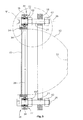
- the mechanical connection between the support frame 18 and the mounting element, which in the embodiment of Fig 1 comprises reflector housing 12, carrying the lens retainer sub-assembly 14 is shown e.g. in Figs. 3 to 5 .
- the mechanical connection is provided by an adjustable bearing arrangement 20 comprising two or more and preferably three ball-type joints 22 arranged at screw-type adjustment elements 24 which are in threaded engagement with support frame 18.
- the reflector housing 12 is mechanically coupled to the ball-type joints 22 as shown in Figs. 3 to 5 .
- the three ball-type joints 22 are arranged along a circle at steps of substantially 120°.
- the lens retainer sub-assembly 14 is located at the light exit opening 28 of the reflector housing 12, through which light exit opening 28 light emitting from a light source 30 will exit from the reflector housing 12.
- a lens or other transparent cover 32 extends over the light exit opening 28 and is mechanically fixed and fastened by means of an annular insert element 34 mounted to the reflector housing 12.
- Three tabs 36 or a mounting flange extend(s) radially outwardly from the reflector housing 12 at its light exit opening 28 so as to form joint connecting regions 38 through which the reflector housing 12 is mechanically connected to the three ball-type joints 22.
- Each of the joint connecting regions 38 are provided with an opening 40 through which an adjustment element 24 extends.
- Each ball-type joint 22 comprises two outer spherical ring elements 42 having a flat outer surface 44 and a tapered inner side 46. Adjacent each of the outer ring elements 42, inner ring elements 48 are arranged, having a spherical convex outer side 50 and a flat inner side 52. The two inner ring elements 48 provide the cone-type element of the joint 22 while the outer ring elements 42 form the hollow ball-type receiving space for receiving the ball-type element of the joint 22.
- Two central thrust washer elements 54 are arranged between the inner spherical ring elements 48 contacting its flat inner surfaces 52.
- Thrust washer elements 54 may be formed of a metallic material, including the same material as reflector housing 12 to reduce the possibility of galvanic action, or may be formed of various non-metallic materials such as polyethyl ethyl keetone, polyamide-imide or other creep-resistant polymers to reduce the coefficient of friction. Thrust washer elements 54 contact the reveal area 56 extending around and defining the opening 40 within a joint connecting region 38 of the reflector housing 12. The assembly consisting of outer ring elements 42, inner ring elements 48, and thrust washer elements 54 are compressed to a predetermined preload by means of lock nut 60, which preferably comprises an elastic stop nut or other shakeproof fastener.
- the predetermined preload is a function of the materials and surface finishes of tabs 36 and thrust washers 54 but is generally within a range at or above the minimum force necessary to clamp reflector housing 12 with sufficient force to prevent detectable vibration, but below the force that would prevent thrust washers 54 from slidingly engaging tabs 36.
- an elastic O-ring 58 is located for further bearing and centering purposes.
- the tilting orientation of the reflector housing 12 relative to the support frame 18 can be adjusted.
- the distances between the ball-type joints 22 within the plane defined by the reflector housing flange or reflector housing mounting tabs will change.
- this distance A is smaller than the distance A' which is given e.g. if the reflector housing 12 is oriented as shown in Fig. 4 .
- the ball-type joints 22 clamp the reveal portion of mounting tabs 36 surrounding openings 40 with sufficient force to prevent rattling but permitting the ball-type joints 22 to slide within openings 40 within the plane defined by the reflector housing mounting flange or mounting tabs 36.
- This plane is generally substantially perpendicular to the movement axis 26 of the adjustment elements 24.
- the adjustment elements 24 are provided with first and second lock nuts 60,62.
- the first lock nut 60 can be used for clamping together the diverse ring elements of the ball-type joints 22 in order to fix the reflector housing 12 relative to the adjusting element 24 and to fix the clamping force between ball-type joints 22 and their respective mounting tabs 36, while both the first and second lock nuts 60 and 62 limit the movement of each adjustment element 24 along its movement axis 26.
- the adjustment element 24 Via an operating portion 64 (screw or nut head 64), the adjustment element 24 can be turned by a tool (screw driver, pliers or the like).
- the approach according to the invention does not utilize springs or other resilient or elastic elements to compensate for tolerances and relative motions of the reflector housing 12 and the support frame 18 through the angle adjustment range of motion.
- O-ring 58 is an elastic element, it is not the primary mechanism by which the invention compensates for the change in distance. Instead, the primary mechanism is the sliding engagement between the ball-type joints and the openings 40. This results in a jitter-free light performance which is accomplished without inducing any significant forces or associated stresses in the assembly.
- the approach according to the invention also offers an advantage over the light unit design which would incorporate a large single ball-type joint on the central access of the light unit by eliminating any large areas of contact where wear and water entrapment could occur.
- the aim adjustment mechanism used according to the invention provides both a rigid aim mechanism once the light unit is adjusted to its target and avoids jittering effects while allowing for both rotational and translational ability to the reflector housing relative to the connecting or mounting element within the provided constraints without stressing the components involved in the mechanism.
- the mounting element that is slidingly engaged by the ball-type joints comprises the reflector housing
- the mounting element could comprise corresponding openings in the support frame 18 or could comprise a flange on the adjustment element 24 that is clamped by the ball-type joint to permit lateral movement about the axis of adjustment element 24.
- the adjustable bearing arrangement of the aim adjustment mechanism according to the invention can also be provided with more than three or only one or two ball-type joints.
- the reflector housing can be tilted along more or less axis in space.
- screw-type adjustment elements 24 other designs for these adjustment elements can be used.
- rods or other adjustment elements without threaded engagement with the mounting element can be used wherein it has to be safeguarded that the adjustment elements can be secured against undesired movements along their respective axes relative to the mounting element. It is therefore intended to include within the invention all such variations and modifications as fall within the scope of the appended claims and equivalents thereof.
Landscapes
- Engineering & Computer Science (AREA)
- Mechanical Engineering (AREA)
- Pivots And Pivotal Connections (AREA)
Priority Applications (2)
| Application Number | Priority Date | Filing Date | Title |
|---|---|---|---|
| EP11150591A EP2474446A1 (fr) | 2011-01-11 | 2011-01-11 | Phare d'avion |
| US13/315,532 US8801240B2 (en) | 2010-12-22 | 2011-12-09 | Aircraft light |
Applications Claiming Priority (1)
| Application Number | Priority Date | Filing Date | Title |
|---|---|---|---|
| EP11150591A EP2474446A1 (fr) | 2011-01-11 | 2011-01-11 | Phare d'avion |
Publications (1)
| Publication Number | Publication Date |
|---|---|
| EP2474446A1 true EP2474446A1 (fr) | 2012-07-11 |
Family
ID=44145971
Family Applications (1)
| Application Number | Title | Priority Date | Filing Date |
|---|---|---|---|
| EP11150591A Withdrawn EP2474446A1 (fr) | 2010-12-22 | 2011-01-11 | Phare d'avion |
Country Status (2)
| Country | Link |
|---|---|
| US (1) | US8801240B2 (fr) |
| EP (1) | EP2474446A1 (fr) |
Cited By (1)
| Publication number | Priority date | Publication date | Assignee | Title |
|---|---|---|---|---|
| WO2021176142A1 (fr) * | 2020-03-04 | 2021-09-10 | Angular Velocity Oy | Ensemble de réglage ancré à une plaque de base solide |
Families Citing this family (4)
| Publication number | Priority date | Publication date | Assignee | Title |
|---|---|---|---|---|
| CN103883993B (zh) * | 2012-12-21 | 2016-04-27 | 深圳市海洋王照明工程有限公司 | 光源支架结构及采用该光源支架结构的嵌入式助航灯 |
| FR3013331B1 (fr) * | 2013-11-15 | 2016-10-28 | Zodiac Aero Electric | Systeme optique d'eclairage pour aeronef |
| CN108423158A (zh) * | 2018-05-11 | 2018-08-21 | 福建中量智汇科技有限公司 | 一种无人机发光起落架 |
| US10773826B1 (en) | 2019-10-15 | 2020-09-15 | Goodrich Lighting Systems, Inc. | Adjustable aiming aircraft light assembly |
Citations (6)
| Publication number | Priority date | Publication date | Assignee | Title |
|---|---|---|---|---|
| US4884174A (en) * | 1988-05-06 | 1989-11-28 | Valeo Vision | Attachment and hinging component, especially for a device to adjust an optical element, particularly for a motor vehicle headlight |
| EP0605172B1 (fr) | 1992-12-28 | 1998-01-21 | Ford Motor Company Limited | Appareil de réglage et de montage pour une unité d'éclairage |
| DE19810480A1 (de) * | 1998-03-11 | 1999-09-16 | Bayerische Motoren Werke Ag | Scheinwerfer für ein Fahrzeug |
| DE20213362U1 (de) * | 2002-08-30 | 2002-10-24 | Boellhoff Gmbh | Befestigungsanordnung für eine Heckleuchte |
| CN2613405Y (zh) | 2003-04-10 | 2004-04-28 | 财团法人车辆研究测试中心 | 汽车头灯旋转装置 |
| DE102005031773A1 (de) | 2005-07-07 | 2007-02-01 | Hella Kgaa Hueck & Co. | Scheinwerfer für Fahrzeuge |
Family Cites Families (4)
| Publication number | Priority date | Publication date | Assignee | Title |
|---|---|---|---|---|
| US4258414A (en) * | 1979-08-01 | 1981-03-24 | Plymouth Products Incorporated | Universal trouble light |
| FR2636578B1 (fr) * | 1988-09-22 | 1993-06-18 | Valeo Vision | Dispositif de reglage d'orientation pour projecteur de vehicule automobile |
| JPH0787041B2 (ja) * | 1988-11-24 | 1995-09-20 | 株式会社小糸製作所 | 前照灯の組立方法 |
| US6533441B2 (en) * | 2001-07-17 | 2003-03-18 | Henry J. Kisiel | Aircraft landing light assembly with resilient vibration dampening mounting system |
-
2011
- 2011-01-11 EP EP11150591A patent/EP2474446A1/fr not_active Withdrawn
- 2011-12-09 US US13/315,532 patent/US8801240B2/en not_active Expired - Fee Related
Patent Citations (7)
| Publication number | Priority date | Publication date | Assignee | Title |
|---|---|---|---|---|
| US4884174A (en) * | 1988-05-06 | 1989-11-28 | Valeo Vision | Attachment and hinging component, especially for a device to adjust an optical element, particularly for a motor vehicle headlight |
| EP0605172B1 (fr) | 1992-12-28 | 1998-01-21 | Ford Motor Company Limited | Appareil de réglage et de montage pour une unité d'éclairage |
| DE19810480A1 (de) * | 1998-03-11 | 1999-09-16 | Bayerische Motoren Werke Ag | Scheinwerfer für ein Fahrzeug |
| DE19810480B4 (de) | 1998-03-11 | 2005-08-18 | Bayerische Motoren Werke Ag | Fahrzeugscheinwerfer mit einem verstellbaren Reflektor |
| DE20213362U1 (de) * | 2002-08-30 | 2002-10-24 | Boellhoff Gmbh | Befestigungsanordnung für eine Heckleuchte |
| CN2613405Y (zh) | 2003-04-10 | 2004-04-28 | 财团法人车辆研究测试中心 | 汽车头灯旋转装置 |
| DE102005031773A1 (de) | 2005-07-07 | 2007-02-01 | Hella Kgaa Hueck & Co. | Scheinwerfer für Fahrzeuge |
Cited By (1)
| Publication number | Priority date | Publication date | Assignee | Title |
|---|---|---|---|---|
| WO2021176142A1 (fr) * | 2020-03-04 | 2021-09-10 | Angular Velocity Oy | Ensemble de réglage ancré à une plaque de base solide |
Also Published As
| Publication number | Publication date |
|---|---|
| US8801240B2 (en) | 2014-08-12 |
| US20120163007A1 (en) | 2012-06-28 |
Similar Documents
| Publication | Publication Date | Title |
|---|---|---|
| US8801240B2 (en) | Aircraft light | |
| US6350043B1 (en) | Behind panel mount, directional lighting bracket | |
| US9551234B2 (en) | Device for controlling pivotable vanes of a turbo-machine | |
| US20070068058A1 (en) | Night vision monocular housing and universal system for using same in various applications | |
| US20180105087A1 (en) | Friction module, friction hinge, and adjustable headrest including the friction module and/or friction hinge | |
| US20130291290A1 (en) | Accessory attachment system for a helmet | |
| WO2021167660A2 (fr) | Réglage de position dans un viseur holographique | |
| EP3407005B1 (fr) | Support de rail cinématique pour le montage d'un dispositif sur un rail d'arme à feu | |
| US9310042B2 (en) | Vehicle headlamp | |
| US5508843A (en) | Sight scope | |
| FR2503387A1 (fr) | Dispositif de liaison entre une piece optique et un support situe a distance de cette piece | |
| JP2019123418A (ja) | 車両の外界センサユニット | |
| US11906269B2 (en) | Turning support for sight | |
| RU2020127398A (ru) | Крепежная конструкция и монтажное основание для внутрисалонного устройства, устанавливаемого путем поворота на лобовом стекле транспортного средства | |
| US4761949A (en) | Thrust reverser position indicator shaft bearing assembly | |
| CN109869663B (zh) | 一种复合隔震照射装置 | |
| US7885001B2 (en) | Tilt lock mechanism and method for a moveable optical or display device | |
| JP2010272373A (ja) | 車両用灯具 | |
| JP6803454B2 (ja) | 車両の外界センサユニット | |
| WO2014110286A1 (fr) | Liseuse | |
| RU2295655C2 (ru) | Направляющий аппарат компрессора и устройство управления поворотной лопаткой в этом аппарате ( варианты ) | |
| RU2434196C2 (ru) | Быстросъемный кронштейн | |
| CN218316530U (zh) | 相机安装组件和车辆 | |
| JP2022516143A (ja) | 器具取付具、当該器具取付具を備える可動プラットフォーム及びその用途 | |
| US10564380B2 (en) | Positional alignment mechanism for a lens assembly |
Legal Events
| Date | Code | Title | Description |
|---|---|---|---|
| PUAI | Public reference made under article 153(3) epc to a published international application that has entered the european phase |
Free format text: ORIGINAL CODE: 0009012 |
|
| AK | Designated contracting states |
Kind code of ref document: A1 Designated state(s): AL AT BE BG CH CY CZ DE DK EE ES FI FR GB GR HR HU IE IS IT LI LT LU LV MC MK MT NL NO PL PT RO RS SE SI SK SM TR |
|
| AX | Request for extension of the european patent |
Extension state: BA ME |
|
| STAA | Information on the status of an ep patent application or granted ep patent |
Free format text: STATUS: THE APPLICATION IS DEEMED TO BE WITHDRAWN |
|
| 18D | Application deemed to be withdrawn |
Effective date: 20130112 |