EP2473311B1 - Setting laser power for laser machining stents from polymer tubing - Google Patents
Setting laser power for laser machining stents from polymer tubing Download PDFInfo
- Publication number
- EP2473311B1 EP2473311B1 EP10752699.8A EP10752699A EP2473311B1 EP 2473311 B1 EP2473311 B1 EP 2473311B1 EP 10752699 A EP10752699 A EP 10752699A EP 2473311 B1 EP2473311 B1 EP 2473311B1
- Authority
- EP
- European Patent Office
- Prior art keywords
- tubing
- laser
- stent
- stents
- power
- Prior art date
- Legal status (The legal status is an assumption and is not a legal conclusion. Google has not performed a legal analysis and makes no representation as to the accuracy of the status listed.)
- Active
Links
Images


Classifications
-
- A—HUMAN NECESSITIES
- A61—MEDICAL OR VETERINARY SCIENCE; HYGIENE
- A61F—FILTERS IMPLANTABLE INTO BLOOD VESSELS; PROSTHESES; DEVICES PROVIDING PATENCY TO, OR PREVENTING COLLAPSING OF, TUBULAR STRUCTURES OF THE BODY, e.g. STENTS; ORTHOPAEDIC, NURSING OR CONTRACEPTIVE DEVICES; FOMENTATION; TREATMENT OR PROTECTION OF EYES OR EARS; BANDAGES, DRESSINGS OR ABSORBENT PADS; FIRST-AID KITS
- A61F2/00—Filters implantable into blood vessels; Prostheses, i.e. artificial substitutes or replacements for parts of the body; Appliances for connecting them with the body; Devices providing patency to, or preventing collapsing of, tubular structures of the body, e.g. stents
- A61F2/82—Devices providing patency to, or preventing collapsing of, tubular structures of the body, e.g. stents
- A61F2/86—Stents in a form characterised by the wire-like elements; Stents in the form characterised by a net-like or mesh-like structure
- A61F2/90—Stents in a form characterised by the wire-like elements; Stents in the form characterised by a net-like or mesh-like structure characterised by a net-like or mesh-like structure
- A61F2/91—Stents in a form characterised by the wire-like elements; Stents in the form characterised by a net-like or mesh-like structure characterised by a net-like or mesh-like structure made from perforated sheet material or tubes, e.g. perforated by laser cuts or etched holes
-
- B—PERFORMING OPERATIONS; TRANSPORTING
- B23—MACHINE TOOLS; METAL-WORKING NOT OTHERWISE PROVIDED FOR
- B23K—SOLDERING OR UNSOLDERING; WELDING; CLADDING OR PLATING BY SOLDERING OR WELDING; CUTTING BY APPLYING HEAT LOCALLY, e.g. FLAME CUTTING; WORKING BY LASER BEAM
- B23K26/00—Working by laser beam, e.g. welding, cutting or boring
- B23K26/02—Positioning or observing the workpiece, e.g. with respect to the point of impact; Aligning, aiming or focusing the laser beam
- B23K26/06—Shaping the laser beam, e.g. by masks or multi-focusing
- B23K26/062—Shaping the laser beam, e.g. by masks or multi-focusing by direct control of the laser beam
- B23K26/0622—Shaping the laser beam, e.g. by masks or multi-focusing by direct control of the laser beam by shaping pulses
- B23K26/0624—Shaping the laser beam, e.g. by masks or multi-focusing by direct control of the laser beam by shaping pulses using ultrashort pulses, i.e. pulses of 1ns or less
-
- A—HUMAN NECESSITIES
- A61—MEDICAL OR VETERINARY SCIENCE; HYGIENE
- A61F—FILTERS IMPLANTABLE INTO BLOOD VESSELS; PROSTHESES; DEVICES PROVIDING PATENCY TO, OR PREVENTING COLLAPSING OF, TUBULAR STRUCTURES OF THE BODY, e.g. STENTS; ORTHOPAEDIC, NURSING OR CONTRACEPTIVE DEVICES; FOMENTATION; TREATMENT OR PROTECTION OF EYES OR EARS; BANDAGES, DRESSINGS OR ABSORBENT PADS; FIRST-AID KITS
- A61F2240/00—Manufacturing or designing of prostheses classified in groups A61F2/00 - A61F2/26 or A61F2/82 or A61F9/00 or A61F11/00 or subgroups thereof
- A61F2240/001—Designing or manufacturing processes
Definitions
- This invention relates to laser machining tubing to form stents.
- Laser machining refers to removal of material accomplished through laser and target material interactions. Generally speaking, these processes include laser drilling, laser cutting, and laser grooving, marking or scribing. Laser machining processes transport photon energy into a target material in the form of thermal energy or photochemical energy. Material is removed by melting and blow away, or by direct vaporization/ablation.
- ultrashort-pulse lasers for high quality laser material processing is particularly useful due to the extremely high intensity, ultrashort-pulse duration ( ⁇ 1 picosecond), and non-contact nature of the processing.
- Ultrashort pulse lasers allow precise and efficient processing, especially at the microscale. Compared with long-pulse lasers and other conventional manufacturing techniques, ultrashort pulse lasers provide precise control of material removal, can be used with an extremely wide range of materials, produce lower thermal damage, and provide the capability for very clean small features. These features make ultrashort-pulse lasers a promising tool for microfabrication, thin film formation, laser cleaning, and medical and biological applications.
- the heat affected zone is a region on the target material that is not removed, but is affected by heat due to the laser.
- the properties of material in the zone can be adversely affected by heat from the laser. Therefore, it is generally desirable to reduce or eliminate heat input beyond removed material, thus reducing or eliminating the heat affected zone.
- One of the many medical applications for laser machining includes fabrication of radially expandable endoprostheses, which are adapted to be implanted in a bodily lumen.
- An “endoprosthesis” corresponds to an artificial device that is placed inside the body.
- a “lumen” refers to a cavity of a tubular organ such as a blood vessel.
- a stent is an example of such an endoprosthesis.
- Stents are generally cylindrically shaped devices, which function to hold open and sometimes expand a segment of a blood vessel or other anatomical lumen such as urinary tracts and bile ducts. Stents are often used in the treatment of atherosclerotic stenosis in blood vessels.
- Stepnosis refers to a narrowing or constriction of the diameter of a bodily passage or orifice. In such treatments, stents reinforce body vessels and prevent restenosis following angioplasty in the vascular system.
- Restenosis refers to the reoccurrence of stenosis in a blood vessel or heart valve after it has been treated (as by balloon angioplasty, stenting, or valvuloplasty) with apparent success.
- the treatment of a diseased site or lesion with a stent involves both delivery and deployment of the stent.
- Delivery refers to introducing and transporting the stent through a bodily lumen to a region, such as a lesion, in a vessel that requires treatment.
- Delivery corresponds to the expanding of the stent within the lumen at the treatment region. Delivery and deployment of a stent are accomplished by positioning the stent about one end of a catheter, inserting the end of the catheter through the skin into a bodily lumen, advancing the catheter in the bodily lumen to a desired treatment location, expanding the stent at the treatment location, and removing the catheter from the lumen.
- the stent In the case of a balloon expandable stent, the stent is mounted about a balloon disposed on the catheter. Mounting the stent typically involves compressing or crimping the stent onto the balloon. The stent is then expanded by inflating the balloon. The balloon may then be deflated and the catheter withdrawn. In the case of a self-expanding stent, the stent may be secured to the catheter via a retractable sheath or a sock. When the stent is in a desired bodily location, the sheath may be withdrawn which allows the stent to self-expand.
- the stent must be able to satisfy a number of mechanical requirements.
- the stent must be capable of withstanding the structural loads, namely radial compressive forces, imposed on the stent as it supports the walls of a vessel. Therefore, the stent must possess adequate radial strength and rigidity.
- Radial strength which is the ability of a stent to resist radial compressive forces, is due to strength around a circumferential direction of the stent.
- the stent Once expanded, the stent must adequately maintain its size and shape throughout its service life despite the various forces that may come to bear on it, including the cyclic loading induced by the beating heart. For example, a radially directed force may tend to cause a stent to recoil inward. Generally, it is desirable to minimize recoil. In addition, the stent must possess sufficient flexibility to allow for crimping, expansion, and cyclic loading without fracturing that would adversely affect stent performance. Finally, the stent must be biocompatible so as not to trigger any adverse vascular responses.
- the structure of a stent is typically composed of scaffolding that includes a pattern or network of interconnecting structural elements often referred to in the art as struts or bar arms.
- the scaffolding can be formed from wires, tubes, or sheets of material rolled into a cylindrical shape.
- the scaffolding is designed so that the stent can be radially compressed (to allow crimping) and radially expanded (to allow deployment).
- Stents have been made of many materials such as metals and polymers, including biodegradable polymeric materials.
- Biodegradable stents are desirable in many treatment applications in which the presence of a stent in a body may be necessary for a limited period of time until its intended function of, for example, achieving and maintaining vascular patency and/or drug delivery is accomplished.
- Stents can be fabricated by forming patterns on tubes or sheets using laser machining. However, as indicated above, the use of laser machining can have adverse effects on the properties of a material, including polymers.
- Document DE 197 45 294 A1 discloses a method of laser machining stents.
- the present invention relates to a method of fabricating a plurality of stents as set forth in the appended claims.
- Various embodiments of the present invention include a method of fabricating a plurality of stents, comprising: providing a plurality of polymer tubing sections that are each formed separately by the same type of processing steps for use in forming stents of the same design; determining for each tubing section a laser power level for use in forming stents from each of the tubing sections with laser machining; and laser machining stent patterns into the tubing sections to form a plurality of stents using the laser power levels determined for each tubing section, wherein the stent patterns comprise a plurality of struts and the laser power determined for each tubing section is selected to obtain repeatable strut widths in the stent patterns formed from the different tubing sections.
- Embodiments of the present invention relating to methods of laser machining of polymer tubing to make a stent that includes setting the power of laser system to obtain repeatable stent dimensions.
- the methods may apply to other laser machining technique, the methods are particularly relevant to ultrashort-pulse laser machining of substrates. These embodiments are suitable for fabricating fine and intricate structures of implantable medical devices such as stents.
- Pulse width refers to the duration of an optical pulse versus time. The duration can be defined in more than one way. Specifically, the pulse duration can be defined as the full width at half maximum (FWHM) of the optical power versus time.
- the ultrashort-pulse laser is clearly distinguishable from conventional continuous wave and long-pulse lasers (nanosecond (10 -9 ) laser) which have significantly longer pulses.
- embodiments of the present method employ femtosecond lasers that have pulses shorter than about 10 -13 second.
- Representative examples of femtosecond lasers include, but are not limited to, a Ti:sapphire laser (735 nm-1035 nm) and an excimer-dye laser (220 nm-300 nm, 380 nm-760 nm).
- stents can have virtually any structural pattern that is compatible with a bodily lumen in which it is implanted.
- a stent is composed of a pattern or network of circumferential rings and longitudinally extending interconnecting structural elements of struts or bar arms.
- the struts are arranged in patterns, which are designed to contact the lumen walls of a vessel and to maintain vascular patency.
- FIG. 1 depicts a stent 10 which is made up of struts 12.
- Stent 10 has interconnected cylindrical rings 14 connected by linking struts or links 16.
- the embodiments disclosed herein are not limited to fabricating stents or to the stent pattern illustrated in FIG. 1 .
- the embodiments are easily applicable to other stent patterns.
- the variations in the structure of patterns are virtually unlimited.
- the outer diameter of a fabricated stent (prior to crimping and deployment) may be between 0.2-5.0 mm.
- a fabricated stent diameter is 2.5-3.5 mm.
- the length of the stents may be between about 6-12 mm.
- the present embodiments are particular relevant to laser machining polymer substrates to form stents, however, the methods although not part of the present invention, may be applicable to other materials such as metals and ceramics or composite materials composed of combinations of polymer, metal, and ceramic.
- Polymers can be biostable, bioabsorbable, biodegradable, or bioerodable.
- Biostable refers to polymers that are not biodegradable.
- biodegradable, bioabsorbable, and bioerodable, as well as degraded, eroded, and absorbed are used interchangeably and refer to polymers that are capable of being completely eroded or absorbed when exposed to bodily fluids such as blood and can be gradually resorbed, absorbed, and/or eliminated by the body.
- a medicated stent may be fabricated by coating the surface of the stent with an active agent or drug, or a polymeric carrier including an active agent or drug.
- the drug coating is typically applied to the stent body or scaffolding after being formed by laser machining.
- the coating is typically much thinner than the struts of the scaffolding, for example, the coating can be 1-5 microns in thickness while the struts can be 140-160 microns thick.
- the stent is fabricated by laser machining a construct to form the device. Material is removed from selected regions of the construct which results in formation of the structure of the device.
- a stent is fabricated by machining a thin-walled tubular member with a laser. Selected regions of the tubing are removed by laser machining to obtain a stent with a desired pattern.
- a beam can be translated or scanned over the surface of a tubing resulting in removal of a trench or kerf extending all the way through a wall of the tubing. When a starting and ending point of a kerf meet, the region surrounded by the kerf drops out or is removed.
- the tube can be translated and rotated to allow machining of tubing.
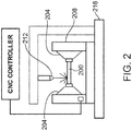
- a stent can be cut from a tubing using a machine-controlled laser as illustrated schematically in FIG. 2.
- FIG. 2 depicts an embodiment of a portion of a machine-controlled system for laser machining a tube.
- a tube 200 is disposed in a rotatable collet fixture 204 of a machine-controlled apparatus 208 for positioning tubing 200 relative to a laser 212.
- tube 200 is rotated and moved axially relative to laser 212 which is also machine-controlled.
- the laser selectively removes the material from the tubing resulting in a pattern cut into the tube.
- the tube is therefore cut into the discrete pattern of the finished stent.
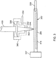
- FIG. 3 depicts a close-up view of a laser beam 408 interacting with a tube 414.
- Laser beam 408 is focused by a focusing lens 338 on tube 414.
- Tube 414 is supported by a controlled rotary collet 337 at one end and an optional tube support pin 339 at another end.
- a coaxial gas jet assembly 340 directs a cold gas jet or stream 342 that exits through a nozzle 344 that cools the machined surface as the beam cuts and ablates a substrate. The gas stream also helps to remove debris from the kerf and cool the region near the beam.
- Gas input is shown by an arrow 354.
- Coaxial gas jet nozzle 344 is centered around a focused beam 352.
- the pressure of the supplied cooling gas is between 2.07 and 6.86 bar (30 and 100 psi).
- An exemplary flow rate of the cooling gas is between 2 and 10 scfh.
- Exemplary cooling gases or process gases include helium, argon, nitrogen, or oxygen.
- a mandrel 360 supported by a mandrel beam block 362 is placed inside the tube and is allowed to roll on the bottom of the tube 414 as the pattern is cut. This acts as a beam/debris block protecting the far wall inner diameter.
- the present invention is applicable to femtosecond pulsed lasers having pulse widths of 5-10 fs, 10-80, 80-120 fs, 120-500, or 500-1000 fs. It is also believed the invention is applicable to lasers with pulse widths greater than 1000 fs (1 ps), greater than 10 ps, in particular, 10-15 ps.
- the repetition rate used for laser machining polymers for stents with a femtosecond laser is generally between 1 and 5 kHz.
- the energy per pulse of such laser machining is generally 2-1000 ⁇ J, more narrowly, 20-30 ⁇ J.
- the fluence of such laser machining is generally 1-20 J/cm 2 , or more narrowly, 5-15 J/cm 2 .
- the average power per pulse or power of a beam can be 10-1000 mW, or more narrowly 50-150 mW.
- Fixed and variable wavelength lasers may be used for laser machining polymers. Exemplary fixed wavelength lasers may have wavelengths at 248 nm, 532 nm, or 800 nm.
- the embodiments of the present invention relate to determining the power of the femtosecond laser used for laser machining a polymer tubing.
- a power is determined for a tubing section that reduces or eliminates undesirable cutting affects.
- the power determination also provides repeatable stent dimensions, such as strut widths, as compared to other tubing sections processed separately prior to laser machining.
- Embodiments of the method include providing a plurality of polymer tubing sections that are each formed separately by the same type of processing steps for use in forming stents of the same design.
- the same design refers to features such as the stent pattern and the dimensions of the structural elements or struts of the stent pattern including thickness and width.
- Other features of a design include mechanical properties such as radial strength and fracture toughness.
- Additional features include morphology properties such as polymer orientation, crystallinity, and the size of crystallites of a semicrystalline polymer.
- the processing of stent precursor constructs or tubing sections is performed so that such features are as close as possible for tubing sections made at different times.
- a laser power level is determined for use in forming stents from each of the tubing sections with laser machining.
- the method further includes laser machining stent patterns into the tubing sections to form a plurality of stents using the laser power levels determined for each tubing section.
- the stent patterns include a plurality of struts. The laser power determined for each tubing section is selected to obtain repeatable strut widths in the stent patterns formed from the different tubing sections.
- a "lot" of tubing refers to a section of tubing made or processed at a given time, for example, a lot of tubing extruded and then radially expanded.
- the inventors unexpectedly found that laser machining different lots with the same power with the same laser yielded stents with different quality and strut widths.
- the different lots were of the same material, PLLA, and all had the same wall thickness.
- the different lots were made at different times either with the same processing conditions or only slightly different processing conditions.
- Quality refers to several aspects of a cut stent pattern.
- One aspect is the degree of smoothness of the cut.
- a poor quality cut can have rough portions on a cut surface, such as flashes which refers to un-cut material that is torn from the excess cut away sections.
- Another aspect of a poor quality cut is "glitter” which refers to re-deposited material as particles large enough to create a reflective surface. Excess melting in portions of the stent pattern are another characteristic of a poor quality cut.
- islands Another characteristic of a poor quality stent pattern are islands, which are portions of tubing that are not intended to be part of the stent pattern that do not fall out of the cut pattern since a region surrounded by a kerf is still attached to a strut. Islands may result when the power is insufficient for a beam to consistently cut all the way through a tubing wall as it travels around a region to be removed.
- the differences in machining the different lots of tubing are a sensitivity to power likely arising from variations in morphology of the polymer in the different lots of tubing.
- the difference in morphology can arise from even the slightest differences in processing conditions. Even slight differences in process conditions will likely result in such morphology variations between lots of tubing.
- it was unknown to the inventors that such minor variations in processing conditions prior to machining could have such a dramatic affect on cutting quality and strut dimensions.
- Inventors have found it essential to compensate for unexpected sensitivity to these variations through adjustment of the power for different lots of tubing.
- the processing referred to above includes forming a tube from a polymer resin using an extrusion process followed by radially expanding and axial elongating the tube.
- a stent is formed by laser machining a stent pattern in the expanded and elongated tube.
- the tube is radially expanded and axially elongated to increase the radial strength and fracture toughness of the tube and a stent made therefrom.
- a semicrystalline polymer such as PLLA, includes crystalline regions separated or surrounded by amorphous regions.
- Morphology includes, but is not limited to, degree of crystallinity, molecular orientation of polymer chains, and crystallite size.
- Molecular orientation refers to the relative orientation of polymer chains along a longitudinal or covalent axis of the polymer chains. The orientation can refer to the orientation of crystalline lamella and to the orientation of polymer chains in the amorphous regions.
- extruders include single screw extruders, intermeshing co-rotating and counterrotating twin-screw extruders and other multiple screw masticating extruders.
- tubing for a stent can be formed with a 1" single screw extruder.
- a temperature range in the extruder is at least 20°C above the Tm of the polymer.
- an exemplary temperature range for PLLA extrusion is 200 - 225 °C.
- exemplary processing conditions for PLLA tubing include a residence time in the extruder of approximately 10 min, quench in room temperature water bath, a die / quench distance of 3 ⁇ 4 in, a pull rate of 16 ft / min, a barrel pressure of 137.89 bar (2000 psi), and a draw down ratio approximately 3:1 (ID die to ID of drawn tube).
- a polymeric tube is radially expanded and axially elongated by increasing the pressure inside the tube and applying a tensile force along the cylindrical axis of the tube, respectively.
- the pressure inside of the tube is increased by conveying a fluid into the tube to increase the internal pressure in the tube.
- the tensile force is applied at one end while holding the other end stationary.
- the tube is heated to a temperature between the glass transition temperature (Tg) and the melting temperature (Tm) of the polymer to allow the radial expansion and axial elongation of the tube.
- the tube is positioned in a cylindrical member or mold.
- the process parameters are adjusted so that the tube expands against the inside surface of the mold so that the outer diameter of the expanded tube is the inside diameter of the mold.
- One end of the tube is sealed or blocked and a gas such as air, nitrogen, oxygen, argon, etc. is conveyed in the other end of the polymer tube to increase the pressure in the tube.
- the tube is heated by a heating source such as a nozzle or nozzles blowing a warm gas onto a portion of the tube.
- a heating source such as a nozzle or nozzles blowing a warm gas onto a portion of the tube.
- the nozzle(s) are translated along the cylindrical axis of a the tube from a proximal end to a distal end, blowing warm gas onto an axial section or portion of the mold as it translates which heats the axial section or portion of the mold and the axial section or portion of the tube within the mold.
- the temperature and nozzle rate are adjusted so that as the nozzle translates, the heated portion expands.
- the radial expansion follows the translating nozzle and propagates along the cylindrical axis of the tube. As the nozzle translates, the an end of the tube is pulled at a specified rate, which is preferably constant.
- the nozzle rate and pull rate are adjusted so that expansion and axial elongation start at the same time and are completed at the same time. Additionally, the nozzle rate and pull rate are preferably constant since the properties of a deformed polymer generally depend on the rate of deformation.
- the tube Prior to the expansion and elongation, the tube is pre-heated close to the deformation temperature. Pre-heating can be performed by a nozzle translated along the length of the tube without the increased pressure and the tension. After the expansion and elongation is completed, the polymer tube is cooled or allowed to cool to below its Tg either before or after decreasing the pressure and/or decreasing tension. Cooling the tube helps insure that the tube maintains the proper shape, size, and length following its formation. A section of tubing expanded in the way described is considered a "lot" of tubing.
- Exemplary processing conditions for a PLLA tube deformation include a deformation temperature of 75-130°C, an expansion pressure of 110 - 140 psi, a nozzle translation rate 0.2-1.2 mm/s, a pull rate of 0.4 - 4.0 mm/s.
- the percent degree of radial expansion (%RE) of a tube is 100% x (Inside Diameter of Expanded Tube /Original Inside Diameter of Tube - 1).
- the percent degree of axial elongation (%AE) is: 100% x (Length of Elongated Tube/Original Length of Tube - 1).
- Exemplary %RE are 200-500% and %AE are 20-200%.
- the degree of crystallinity of exemplary expanded PLLA tubes and stents made therefrom are 20-50%, or more narrowly, 45-50%.
- the heat affected zone is a region on the target material that is not removed, but is affected by thermal energy from the laser.
- the properties of material in the zone vary as a function of distance.
- Stent performance may be increased by reducing or eliminating the variation in properties of the heat affected zone. Stent performance includes having a high radial strength sufficient maintain patency, low recoil, and resistance to cracking upon crimping and deployment.
- the inventors have found that the variation of properties in the heat affected zone depends on the power. As the power increases the depth and variation in properties changes. This has been demonstrated by nanoindentation results. Therefore, a lower power is preferable.
- a selected machining power for making a stent from a selected tubing lot includes determining an a approximate threshold power level for the laser to cut a kerf or channel all the way through the tubing wall.
- the threshold power can correspond to the power level that allows the laser beam to cut through a length of tubing completely when the beam in scanned over the length, in spite of slight variations in the thickness and properties in different portions of the tubing.
- a power level that results in portions along the length that are cut all the way through and portions along the length which are not when the laser is scanned along the length is below the threshold power.
- the length of such a section for determining the threshold power may be 0.2 - 20 mm, or more narrowly, 0.2 - 0.5 mm, 0.5 - 1 mm, 1 - 5 mm, 5 - 10 mm, or 10 - 20 mm.
- Each lot of tubing can have a different threshold power level. Any difference or change to the material such as thickness, percent radial expansion, percent axial elongation, or crystallinity may alter the threshold power.
- the inventors have found that different lots of PLLA tubing have different threshold power levels.
- the threshold power may be the stent cutting power which is the power used to laser machine stents from the lot of tubing.
- the stent cutting power level may be above the threshold power.
- exemplary stent cutting power level can be A x threshold power, where "A" is between 100% and 120%, or more narrowly, 100% and 110%. "A” can be between 100% and 102%, 102% and 105%, 105% and 108%, 108% and 112%, or 112% and 120%. In other embodiment, A can be between 120-150%, or greater than 150%.
- a preferable stent cutting power level is 110% of the threshold power level.
- a stent pattern cut using the power is free or almost free of flash, glitter, or melted portions.
- the threshold power can be determined by first selecting an initial power level that is believed to cut a kerf or channel all the way through the tubing wall, as described above. The presumption is then verified by machining a length of the tubing at the initial power level. Then, a length of tubing is machined at a power level lower than the initial power and the machining portion is inspected. The process is repeated by making discrete steps downward in power until a power level (“sub-threshold power”) is found that results in portions along the machined length that are cut all the way through and portions are not after the laser is scanned over length.
- sub-threshold power a power level
- the lowest power level selected that is greater than the sub-threshold power can be selected as the threshold power. In other embodiments, one or more additional power levels between the two lowest power levels can be tested to obtain a more accurate value of the threshold power.
- the following set of examples describes results of determining laser machining power for four lots of PLLA tubing.
- Each lot of tubing was formed from an extrusion process from 100% PLLA resin.
- the extruded PLLA tubes were radially expanded according the process described above.
- the target %RE was 400%.
- Titanium-Sapphire fixed wavelength lasers were used with a wavelength of 800 nm.
- the pulse widths of the lasers ranged from 95-120 fs with a repetition rate of 5 kHz.
- the fluence was between 10 ⁇ 5 kJ/cm 2 .
- the selected machining powers (110% x threshold power) determined for various lots of tubing were between 90-140 mW.
- Table 1 provides the selected machining powers that were determined for the four lots of tubing for three different lasers. The deformation parameters for each lot of tubing is given in Table 2. Table 1. Selected machining power for tubing determined for four lots and three lasers. Lot 1 Power (mW) Lot 2 Power (mW) Lot 3 Power (mW) Lot 4 Power (mW) Laser 1 140 135 128 140 Laser 2 105 110 90 --- Laser 3 --- 130 128 100 Table 2. Deformation parameters for lots of tubing listed in Table 1.
- the inventors observed that a repeatable strut width was not obtained when the same power was used to machine different lots of tubing.
- the inventors also observed that for a given power, different strut widths were obtained from tubing with different degrees of radial expansion. The laser power had to be adjusted each time to obtain a desired strut width.
- the effect of power and the degree of radial expansion was studied by laser machining two PLLA tubes with two different %RE, 300% and 400%, at several power levels.
- the strut widths of each of the stents were measured to determine the effect of power on strut width.
- the expanded inside and outside diameter of the expanded tubes are approximately the same.
- the two groups were cut with the same laser and the same stent pattern program.
- the measurements were taken with a Keyence optical microscope at 200x, calibrated to a pin gauge. Power dependence shows that if same power is used for all tubes, different strut widths will be obtained.
- Stent patterns cut from a PLLA tube at two different power levels showed the effect of power on the quality of cutting.
- the degree of radial expansion of the PLLA tubes was 400%.
- the expanded tubing had a 3.45 mm (0.136 in) OD and a 0.15 mm (0.006 in) nominal wall thickness.
- the pulse width of the laser was 92 fs and the height of cooling nozzle blowing helium gas was 0.35. Exhaust was 5.84 m/s (1150 ft/min).
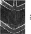
- Stent patterns were cut at two power levels, 70 mW and 90 mW.
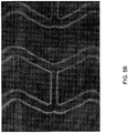
- FIGs. 5A-D are exemplary images of portions of the stent patterns cut under these conditions.
- FIG 5A illustrates an island and flash.
- FIG. 5B shows flash.
- FIG. 5C shows roughness.
- FIG. 5D shows flash and glitter.
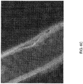
- FIGs. 6A-C are exemplary images of portions of the stent patterns cut with a power level of 90 mW.
- FIGs. 6A-B are portions cut with helium cooling gas flow of 4 scfh and
- FIG. 6C are portions cut with the flow at 6 scfh.
- the flash were no longer present, however, melt and glitter were.
- the helium flow was raised from 4 to 5, but the melt and glitter remained (not shown).
- FIG. 6C after the flow was increased to 6 scfh, the melt and glitter were no longer present.
- substantially the same or “almost the same” can refer to within 0.01% to 5%.
Description
- This invention relates to laser machining tubing to form stents.
- This invention relates to laser machining of devices such as stents. Laser machining refers to removal of material accomplished through laser and target material interactions. Generally speaking, these processes include laser drilling, laser cutting, and laser grooving, marking or scribing. Laser machining processes transport photon energy into a target material in the form of thermal energy or photochemical energy. Material is removed by melting and blow away, or by direct vaporization/ablation.
- The application of ultrashort-pulse lasers for high quality laser material processing is particularly useful due to the extremely high intensity, ultrashort-pulse duration (<1 picosecond), and non-contact nature of the processing. Ultrashort pulse lasers allow precise and efficient processing, especially at the microscale. Compared with long-pulse lasers and other conventional manufacturing techniques, ultrashort pulse lasers provide precise control of material removal, can be used with an extremely wide range of materials, produce lower thermal damage, and provide the capability for very clean small features. These features make ultrashort-pulse lasers a promising tool for microfabrication, thin film formation, laser cleaning, and medical and biological applications.
- However, laser machining of a substrate tends to result in unwanted heat transfer to a substrate resulting in a heat affected zone. The heat affected zone is a region on the target material that is not removed, but is affected by heat due to the laser. The properties of material in the zone can be adversely affected by heat from the laser. Therefore, it is generally desirable to reduce or eliminate heat input beyond removed material, thus reducing or eliminating the heat affected zone.
- One of the many medical applications for laser machining includes fabrication of radially expandable endoprostheses, which are adapted to be implanted in a bodily lumen. An "endoprosthesis" corresponds to an artificial device that is placed inside the body. A "lumen" refers to a cavity of a tubular organ such as a blood vessel.
- A stent is an example of such an endoprosthesis. Stents are generally cylindrically shaped devices, which function to hold open and sometimes expand a segment of a blood vessel or other anatomical lumen such as urinary tracts and bile ducts. Stents are often used in the treatment of atherosclerotic stenosis in blood vessels. "Stenosis" refers to a narrowing or constriction of the diameter of a bodily passage or orifice. In such treatments, stents reinforce body vessels and prevent restenosis following angioplasty in the vascular system. "Restenosis" refers to the reoccurrence of stenosis in a blood vessel or heart valve after it has been treated (as by balloon angioplasty, stenting, or valvuloplasty) with apparent success.
- The treatment of a diseased site or lesion with a stent involves both delivery and deployment of the stent. "Delivery" refers to introducing and transporting the stent through a bodily lumen to a region, such as a lesion, in a vessel that requires treatment. "Deployment" corresponds to the expanding of the stent within the lumen at the treatment region. Delivery and deployment of a stent are accomplished by positioning the stent about one end of a catheter, inserting the end of the catheter through the skin into a bodily lumen, advancing the catheter in the bodily lumen to a desired treatment location, expanding the stent at the treatment location, and removing the catheter from the lumen.
- In the case of a balloon expandable stent, the stent is mounted about a balloon disposed on the catheter. Mounting the stent typically involves compressing or crimping the stent onto the balloon. The stent is then expanded by inflating the balloon. The balloon may then be deflated and the catheter withdrawn. In the case of a self-expanding stent, the stent may be secured to the catheter via a retractable sheath or a sock. When the stent is in a desired bodily location, the sheath may be withdrawn which allows the stent to self-expand.
- The stent must be able to satisfy a number of mechanical requirements. First, the stent must be capable of withstanding the structural loads, namely radial compressive forces, imposed on the stent as it supports the walls of a vessel. Therefore, the stent must possess adequate radial strength and rigidity. Radial strength, which is the ability of a stent to resist radial compressive forces, is due to strength around a circumferential direction of the stent.
- Once expanded, the stent must adequately maintain its size and shape throughout its service life despite the various forces that may come to bear on it, including the cyclic loading induced by the beating heart. For example, a radially directed force may tend to cause a stent to recoil inward. Generally, it is desirable to minimize recoil. In addition, the stent must possess sufficient flexibility to allow for crimping, expansion, and cyclic loading without fracturing that would adversely affect stent performance. Finally, the stent must be biocompatible so as not to trigger any adverse vascular responses.
- The structure of a stent is typically composed of scaffolding that includes a pattern or network of interconnecting structural elements often referred to in the art as struts or bar arms. The scaffolding can be formed from wires, tubes, or sheets of material rolled into a cylindrical shape. The scaffolding is designed so that the stent can be radially compressed (to allow crimping) and radially expanded (to allow deployment).
- Stents have been made of many materials such as metals and polymers, including biodegradable polymeric materials. Biodegradable stents are desirable in many treatment applications in which the presence of a stent in a body may be necessary for a limited period of time until its intended function of, for example, achieving and maintaining vascular patency and/or drug delivery is accomplished.
- Stents can be fabricated by forming patterns on tubes or sheets using laser machining. However, as indicated above, the use of laser machining can have adverse effects on the properties of a material, including polymers.
- Document
DE 197 45 294 A1 discloses a method of laser machining stents. - The present invention relates to a method of fabricating a plurality of stents as set forth in the appended claims.
- Various embodiments of the present invention include a method of fabricating a plurality of stents, comprising: providing a plurality of polymer tubing sections that are each formed separately by the same type of processing steps for use in forming stents of the same design; determining for each tubing section a laser power level for use in forming stents from each of the tubing sections with laser machining; and laser machining stent patterns into the tubing sections to form a plurality of stents using the laser power levels determined for each tubing section, wherein the stent patterns comprise a plurality of struts and the laser power determined for each tubing section is selected to obtain repeatable strut widths in the stent patterns formed from the different tubing sections.
- Further embodiments of the present invention include a method of fabricating a plurality of stents, comprising: laser machining a plurality of polymer tubing sections to form stents comprising a plurality of struts, wherein the tubing sections are each formed separately by the same type of processing steps for use in forming stents of the same design, wherein the power of the laser machining is adjusted for each tubing section to obtain repeatable strut widths for stents formed from different tubing sections.
-
-
FIG. 1 depicts a stent. -
FIG. 2 depicts an embodiment of a portion of a machine-controlled system for laser machining a tube. -
FIG. 3 depicts a close-up axial view of a region where a laser beam interacts with a tube. -
FIG. 4 is a plot of the strut width versus laser power for tubing made with two different degrees of radial expansion. -
FIGs. 5A-D depict images of a stent pattern formed using a laser using 70 mW of power. -
FIGs. 6A-C depict images of a stent pattern formed using a laser using 90 mW of power. - Embodiments of the present invention relating to methods of laser machining of polymer tubing to make a stent that includes setting the power of laser system to obtain repeatable stent dimensions. Although the methods may apply to other laser machining technique, the methods are particularly relevant to ultrashort-pulse laser machining of substrates. These embodiments are suitable for fabricating fine and intricate structures of implantable medical devices such as stents. "Ultrashort-pulse lasers" refer to lasers having pulses with widths or durations shorter than about a picosecond (=10-12). "Pulse width" refers to the duration of an optical pulse versus time. The duration can be defined in more than one way. Specifically, the pulse duration can be defined as the full width at half maximum (FWHM) of the optical power versus time.
- Ultrashort-pulse lasers can include both picosecond and femtosecond (=10-15) lasers. The ultrashort-pulse laser is clearly distinguishable from conventional continuous wave and long-pulse lasers (nanosecond (10-9) laser) which have significantly longer pulses. In particular, embodiments of the present method employ femtosecond lasers that have pulses shorter than about 10-13 second. Representative examples of femtosecond lasers include, but are not limited to, a Ti:sapphire laser (735 nm-1035 nm) and an excimer-dye laser (220 nm-300 nm, 380 nm-760 nm).
- As indicated above, embodiments of the laser machining method described above are used in the fabrication of stents. In general, stents can have virtually any structural pattern that is compatible with a bodily lumen in which it is implanted. Typically, a stent is composed of a pattern or network of circumferential rings and longitudinally extending interconnecting structural elements of struts or bar arms. In general, the struts are arranged in patterns, which are designed to contact the lumen walls of a vessel and to maintain vascular patency.
- An exemplary structure of a stent is shown in
FIG. 1. FIG. 1 depicts a stent 10 which is made up ofstruts 12. Stent 10 has interconnectedcylindrical rings 14 connected by linking struts or links 16. The embodiments disclosed herein are not limited to fabricating stents or to the stent pattern illustrated inFIG. 1 . The embodiments are easily applicable to other stent patterns. The variations in the structure of patterns are virtually unlimited. The outer diameter of a fabricated stent (prior to crimping and deployment) may be between 0.2-5.0 mm. For coronary applications, a fabricated stent diameter is 2.5-3.5 mm. The length of the stents may be between about 6-12 mm. - The present embodiments are particular relevant to laser machining polymer substrates to form stents, however, the methods although not part of the present invention, may be applicable to other materials such as metals and ceramics or composite materials composed of combinations of polymer, metal, and ceramic. Polymers can be biostable, bioabsorbable, biodegradable, or bioerodable. Biostable refers to polymers that are not biodegradable. The terms biodegradable, bioabsorbable, and bioerodable, as well as degraded, eroded, and absorbed, are used interchangeably and refer to polymers that are capable of being completely eroded or absorbed when exposed to bodily fluids such as blood and can be gradually resorbed, absorbed, and/or eliminated by the body. In addition, a medicated stent may be fabricated by coating the surface of the stent with an active agent or drug, or a polymeric carrier including an active agent or drug. The drug coating is typically applied to the stent body or scaffolding after being formed by laser machining. The coating is typically much thinner than the struts of the scaffolding, for example, the coating can be 1-5 microns in thickness while the struts can be 140-160 microns thick.
- The stent, is fabricated by laser machining a construct to form the device. Material is removed from selected regions of the construct which results in formation of the structure of the device. In particular, a stent is fabricated by machining a thin-walled tubular member with a laser. Selected regions of the tubing are removed by laser machining to obtain a stent with a desired pattern. Specifically, a beam can be translated or scanned over the surface of a tubing resulting in removal of a trench or kerf extending all the way through a wall of the tubing. When a starting and ending point of a kerf meet, the region surrounded by the kerf drops out or is removed. Alternatively or additionally, the tube can be translated and rotated to allow machining of tubing.
- In exemplary embodiments, a stent can be cut from a tubing using a machine-controlled laser as illustrated schematically in
FIG. 2. FIG. 2 depicts an embodiment of a portion of a machine-controlled system for laser machining a tube. InFIG. 2 , atube 200 is disposed in arotatable collet fixture 204 of a machine-controlledapparatus 208 forpositioning tubing 200 relative to alaser 212. According to machine-encoded instructions,tube 200 is rotated and moved axially relative tolaser 212 which is also machine-controlled. The laser selectively removes the material from the tubing resulting in a pattern cut into the tube. The tube is therefore cut into the discrete pattern of the finished stent. -
FIG. 3 depicts a close-up view of alaser beam 408 interacting with atube 414.Laser beam 408 is focused by a focusinglens 338 ontube 414.Tube 414 is supported by a controlledrotary collet 337 at one end and an optionaltube support pin 339 at another end. A coaxialgas jet assembly 340 directs a cold gas jet or stream 342 that exits through anozzle 344 that cools the machined surface as the beam cuts and ablates a substrate. The gas stream also helps to remove debris from the kerf and cool the region near the beam. Gas input is shown by anarrow 354. Coaxialgas jet nozzle 344 is centered around afocused beam 352. In some embodiments, the pressure of the supplied cooling gas is between 2.07 and 6.86 bar (30 and 100 psi). An exemplary flow rate of the cooling gas is between 2 and 10 scfh. Exemplary cooling gases or process gases include helium, argon, nitrogen, or oxygen. - It may also be necessary to block
focused beam 352 as it cuts through the top surface of the tube to prevent the beam, along with the molten material and debris from the cut, from impinging on the inside opposite surface oftube 414. To this end, amandrel 360 supported by amandrel beam block 362 is placed inside the tube and is allowed to roll on the bottom of thetube 414 as the pattern is cut. This acts as a beam/debris block protecting the far wall inner diameter. - The present invention is applicable to femtosecond pulsed lasers having pulse widths of 5-10 fs, 10-80, 80-120 fs, 120-500, or 500-1000 fs. It is also believed the invention is applicable to lasers with pulse widths greater than 1000 fs (1 ps), greater than 10 ps, in particular, 10-15 ps.
- The repetition rate used for laser machining polymers for stents with a femtosecond laser is generally between 1 and 5 kHz. The energy per pulse of such laser machining is generally 2-1000 µJ, more narrowly, 20-30 µJ. The fluence of such laser machining is generally 1-20 J/cm2, or more narrowly, 5-15 J/cm2. The average power per pulse or power of a beam can be 10-1000 mW, or more narrowly 50-150 mW. Fixed and variable wavelength lasers may be used for laser machining polymers. Exemplary fixed wavelength lasers may have wavelengths at 248 nm, 532 nm, or 800 nm.
- The embodiments of the present invention relate to determining the power of the femtosecond laser used for laser machining a polymer tubing. A power is determined for a tubing section that reduces or eliminates undesirable cutting affects. The power determination also provides repeatable stent dimensions, such as strut widths, as compared to other tubing sections processed separately prior to laser machining.
- Embodiments of the method include providing a plurality of polymer tubing sections that are each formed separately by the same type of processing steps for use in forming stents of the same design. The same design refers to features such as the stent pattern and the dimensions of the structural elements or struts of the stent pattern including thickness and width. Other features of a design include mechanical properties such as radial strength and fracture toughness. Additional features include morphology properties such as polymer orientation, crystallinity, and the size of crystallites of a semicrystalline polymer. The processing of stent precursor constructs or tubing sections is performed so that such features are as close as possible for tubing sections made at different times.
- For each tubing section, a laser power level is determined for use in forming stents from each of the tubing sections with laser machining. The method further includes laser machining stent patterns into the tubing sections to form a plurality of stents using the laser power levels determined for each tubing section. The stent patterns include a plurality of struts. The laser power determined for each tubing section is selected to obtain repeatable strut widths in the stent patterns formed from the different tubing sections.
- The inventors had used a femtosecond laser (120 fs, fluence =10±5) to machine PLLA tubes to form stents. The machining power was set to a value that was believed to be significantly higher than a minimum value required to machine through the tubing to form struts. The inventors used the same power for all lots of tubing. A "lot" of tubing refers to a section of tubing made or processed at a given time, for example, a lot of tubing extruded and then radially expanded.
- Specifically, the inventors unexpectedly found that laser machining different lots with the same power with the same laser yielded stents with different quality and strut widths. The different lots were of the same material, PLLA, and all had the same wall thickness. The different lots were made at different times either with the same processing conditions or only slightly different processing conditions.
- The inventors observed that the quality of a machined stent and stent dimensions obtained from laser machining different lots of tubing was extremely sensitive the laser power. "Quality" refers to several aspects of a cut stent pattern. One aspect is the degree of smoothness of the cut. A poor quality cut can have rough portions on a cut surface, such as flashes which refers to un-cut material that is torn from the excess cut away sections. Another aspect of a poor quality cut is "glitter" which refers to re-deposited material as particles large enough to create a reflective surface. Excess melting in portions of the stent pattern are another characteristic of a poor quality cut. Another characteristic of a poor quality stent pattern are islands, which are portions of tubing that are not intended to be part of the stent pattern that do not fall out of the cut pattern since a region surrounded by a kerf is still attached to a strut. Islands may result when the power is insufficient for a beam to consistently cut all the way through a tubing wall as it travels around a region to be removed.
- The differences in machining the different lots of tubing are a sensitivity to power likely arising from variations in morphology of the polymer in the different lots of tubing. The difference in morphology can arise from even the slightest differences in processing conditions. Even slight differences in process conditions will likely result in such morphology variations between lots of tubing. However, it was unknown to the inventors that such minor variations in processing conditions prior to machining could have such a dramatic affect on cutting quality and strut dimensions. Inventors have found it essential to compensate for unexpected sensitivity to these variations through adjustment of the power for different lots of tubing.
- The processing referred to above includes forming a tube from a polymer resin using an extrusion process followed by radially expanding and axial elongating the tube. A stent is formed by laser machining a stent pattern in the expanded and elongated tube. The tube is radially expanded and axially elongated to increase the radial strength and fracture toughness of the tube and a stent made therefrom.
- A semicrystalline polymer, such as PLLA, includes crystalline regions separated or surrounded by amorphous regions. Morphology includes, but is not limited to, degree of crystallinity, molecular orientation of polymer chains, and crystallite size. Molecular orientation refers to the relative orientation of polymer chains along a longitudinal or covalent axis of the polymer chains. The orientation can refer to the orientation of crystalline lamella and to the orientation of polymer chains in the amorphous regions.
- With regard to making a tube by extrusion, representative examples of extruders include single screw extruders, intermeshing co-rotating and counterrotating twin-screw extruders and other multiple screw masticating extruders. For example, tubing for a stent can be formed with a 1" single screw extruder. A temperature range in the extruder is at least 20°C above the Tm of the polymer. For example, an exemplary temperature range for PLLA extrusion is 200 - 225 °C. Other exemplary processing conditions for PLLA tubing include a residence time in the extruder of approximately 10 min, quench in room temperature water bath, a die / quench distance of ¾ in, a pull rate of 16 ft / min, a barrel pressure of 137.89 bar (2000 psi), and a draw down ratio approximately 3:1 (ID die to ID of drawn tube).
- A polymeric tube is radially expanded and axially elongated by increasing the pressure inside the tube and applying a tensile force along the cylindrical axis of the tube, respectively. The pressure inside of the tube is increased by conveying a fluid into the tube to increase the internal pressure in the tube. Preferably, the tensile force is applied at one end while holding the other end stationary. The tube is heated to a temperature between the glass transition temperature (Tg) and the melting temperature (Tm) of the polymer to allow the radial expansion and axial elongation of the tube.
- At the start of the process, the tube is positioned in a cylindrical member or mold. The process parameters are adjusted so that the tube expands against the inside surface of the mold so that the outer diameter of the expanded tube is the inside diameter of the mold. One end of the tube is sealed or blocked and a gas such as air, nitrogen, oxygen, argon, etc. is conveyed in the other end of the polymer tube to increase the pressure in the tube.
- The tube is heated by a heating source such as a nozzle or nozzles blowing a warm gas onto a portion of the tube. The nozzle(s) are translated along the cylindrical axis of a the tube from a proximal end to a distal end, blowing warm gas onto an axial section or portion of the mold as it translates which heats the axial section or portion of the mold and the axial section or portion of the tube within the mold. The temperature and nozzle rate are adjusted so that as the nozzle translates, the heated portion expands. The radial expansion follows the translating nozzle and propagates along the cylindrical axis of the tube. As the nozzle translates, the an end of the tube is pulled at a specified rate, which is preferably constant.
- The nozzle rate and pull rate are adjusted so that expansion and axial elongation start at the same time and are completed at the same time. Additionally, the nozzle rate and pull rate are preferably constant since the properties of a deformed polymer generally depend on the rate of deformation.
- Prior to the expansion and elongation, the tube is pre-heated close to the deformation temperature. Pre-heating can be performed by a nozzle translated along the length of the tube without the increased pressure and the tension. After the expansion and elongation is completed, the polymer tube is cooled or allowed to cool to below its Tg either before or after decreasing the pressure and/or decreasing tension. Cooling the tube helps insure that the tube maintains the proper shape, size, and length following its formation. A section of tubing expanded in the way described is considered a "lot" of tubing.
- Any slight variations in the processing conditions from lot to lot can result in differences in morphology from lot to lot. Variations can result from adjustments to processing conditions so that the expansion occurs in the manner desired, as described above. Such slight variations in processing conditions unexpectedly alter the power requirements for obtaining a quality machined stent with repeatable strut dimensions.
- Exemplary processing conditions for a PLLA tube deformation include a deformation temperature of 75-130°C, an expansion pressure of 110 - 140 psi, a nozzle translation rate 0.2-1.2 mm/s, a pull rate of 0.4 - 4.0 mm/s.
- The percent degree of radial expansion (%RE) of a tube is 100% x (Inside Diameter of Expanded Tube /Original Inside Diameter of Tube - 1). The percent degree of axial elongation (%AE) is: 100% x (Length of Elongated Tube/Original Length of Tube - 1). Exemplary %RE are 200-500% and %AE are 20-200%. The degree of crystallinity of exemplary expanded PLLA tubes and stents made therefrom are 20-50%, or more narrowly, 45-50%.
- In addition to selecting the power for quality and repeatability, power is also selected to reduce the heat affected zone of a machined substrate. As mentioned above, the heat affected zone is a region on the target material that is not removed, but is affected by thermal energy from the laser. In the heat affected zone, the properties of material in the zone vary as a function of distance. Stent performance may be increased by reducing or eliminating the variation in properties of the heat affected zone. Stent performance includes having a high radial strength sufficient maintain patency, low recoil, and resistance to cracking upon crimping and deployment.
- The inventors have found that the variation of properties in the heat affected zone depends on the power. As the power increases the depth and variation in properties changes. This has been demonstrated by nanoindentation results. Therefore, a lower power is preferable.
- In some embodiments of the invention, a selected machining power for making a stent from a selected tubing lot includes determining an a approximate threshold power level for the laser to cut a kerf or channel all the way through the tubing wall. The threshold power can correspond to the power level that allows the laser beam to cut through a length of tubing completely when the beam in scanned over the length, in spite of slight variations in the thickness and properties in different portions of the tubing. A power level that results in portions along the length that are cut all the way through and portions along the length which are not when the laser is scanned along the length is below the threshold power. The length of such a section for determining the threshold power may be 0.2 - 20 mm, or more narrowly, 0.2 - 0.5 mm, 0.5 - 1 mm, 1 - 5 mm, 5 - 10 mm, or 10 - 20 mm.
- Each lot of tubing can have a different threshold power level. Any difference or change to the material such as thickness, percent radial expansion, percent axial elongation, or crystallinity may alter the threshold power. The inventors have found that different lots of PLLA tubing have different threshold power levels.
- In some embodiments, the threshold power may be the stent cutting power which is the power used to laser machine stents from the lot of tubing. In other embodiments, the stent cutting power level may be above the threshold power. In such embodiments, exemplary stent cutting power level can be A x threshold power, where "A" is between 100% and 120%, or more narrowly, 100% and 110%. "A" can be between 100% and 102%, 102% and 105%, 105% and 108%, 108% and 112%, or 112% and 120%. In other embodiment, A can be between 120-150%, or greater than 150%.
- The inventors have found that a preferable stent cutting power level is 110% of the threshold power level. In some embodiments, a stent pattern cut using the power is free or almost free of flash, glitter, or melted portions.
- In some embodiments, the threshold power can be determined by first selecting an initial power level that is believed to cut a kerf or channel all the way through the tubing wall, as described above. The presumption is then verified by machining a length of the tubing at the initial power level. Then, a length of tubing is machined at a power level lower than the initial power and the machining portion is inspected. The process is repeated by making discrete steps downward in power until a power level ("sub-threshold power") is found that results in portions along the machined length that are cut all the way through and portions are not after the laser is scanned over length.
- In some embodiments, the lowest power level selected that is greater than the sub-threshold power can be selected as the threshold power. In other embodiments, one or more additional power levels between the two lowest power levels can be tested to obtain a more accurate value of the threshold power.
- The examples and experimental data set forth below are for illustrative purposes only and are in no way meant to limit the invention. The following examples are given to aid in understanding the invention, but it is to be understood that the invention is not limited to the particular materials or procedures of examples.
- The following set of examples describes results of determining laser machining power for four lots of PLLA tubing. Each lot of tubing was formed from an extrusion process from 100% PLLA resin. The dimensions of the tubing, the extruded dimensions, are: outside diameter (OD) = 0.066 inch (1.676 mm) and inside diameter (ID) = 0.025 inch (0.635 mm). The extruded PLLA tubes were radially expanded according the process described above. The target %RE was 400%.
- Titanium-Sapphire fixed wavelength lasers were used with a wavelength of 800 nm. The pulse widths of the lasers ranged from 95-120 fs with a repetition rate of 5 kHz. The fluence was between 10±5 kJ/cm2. For a given laser, it was found that each lot had a different selected machining power that was determined. Additionally, for a given lot of tubing, the selected machining power was different for each laser. The selected machining powers (110% x threshold power) determined for various lots of tubing were between 90-140 mW.
- Table 1 provides the selected machining powers that were determined for the four lots of tubing for three different lasers. The deformation parameters for each lot of tubing is given in Table 2.
Table 1. Selected machining power for tubing determined for four lots and three lasers. Lot 1 Power (mW) Lot 2 Power (mW) Lot 3 Power (mW) Lot 4 Power (mW) Laser 1 140 135 128 140 Laser 2 105 110 90 --- Laser 3 --- 130 128 100 Table 2. Deformation parameters for lots of tubing listed in Table 1. Deformation Parameters Lot 1 Lot 2 Lot 3 Lot 4 Expand Heat (F) 166 185 178 180 Expand Air Flow (scfh) 60 60 60 60 Pre-heat Dwell (sec) 32 30 38 32 Heat Nozzle Speed (mm/s) 0.32 0.30 .38 .32 Expand Pressure (psi) 110 130 110 115 Number of Passes 1 1 1 1 Initial Tension Position (mm) 25 25 25 25 Pre-Tension (Grams) 180 180 180 180 Set Heat (F) 32 32 32 32 Set Air Flow (scfh) 20 20 20 20 Set Heat Dwell (min) 0 0 0 0 Cool Time (sec) 30 30 30 30 Tubing Start OD (thou in) 66 66 66 66 Tubing Start ID (thou in) 25 25 25 25 Tubing End OD (thou in) 136 136 136 136 Tubing End ID (thou in) 124.2 124.2 124.2 124.2 - The effect of power and the degree of radial expansion on strut width was studied.
- The inventors observed that a repeatable strut width was not obtained when the same power was used to machine different lots of tubing. The inventors also observed that for a given power, different strut widths were obtained from tubing with different degrees of radial expansion. The laser power had to be adjusted each time to obtain a desired strut width.
- The effect of power and the degree of radial expansion was studied by laser machining two PLLA tubes with two different %RE, 300% and 400%, at several power levels. The strut widths of each of the stents were measured to determine the effect of power on strut width. The expanded inside and outside diameter of the expanded tubes are approximately the same.
- A summary of the strut width data is shown in Table 3 and the data is plotted in
FIG. 4 .Table 3. Laser machining data showing dependence of strut width on power and radial expansion. % RE Power Strut width (inch) 300 80 0.00674 300 90 0.00659 300 103 0.00653 300 123 0.00642 300 145 0.00636 400 70 0.00704 400 90 0.00693 400 120 0.00683 - The data in Table 3 and
FIG. 4 demonstrate that: - 1. As the power increases when laser machining a given lot of tubing, the strut width decreases. The trend was apparent on tubing with two different radial expansions studied.
- 2. The degree of radial expansion affected strut width.
- The two groups were cut with the same laser and the same stent pattern program. The measurements were taken with a Keyence optical microscope at 200x, calibrated to a pin gauge. Power dependence shows that if same power is used for all tubes, different strut widths will be obtained.
- Stent patterns cut from a PLLA tube at two different power levels showed the effect of power on the quality of cutting. The degree of radial expansion of the PLLA tubes was 400%. The expanded tubing had a 3.45 mm (0.136 in) OD and a 0.15 mm (0.006 in) nominal wall thickness. The pulse width of the laser was 92 fs and the height of cooling nozzle blowing helium gas was 0.35. Exhaust was 5.84 m/s (1150 ft/min). Stent patterns were cut at two power levels, 70 mW and 90 mW.
- The stent patterns cut with a power level of 70mW and an helium cooling flow gas of 4scfh had flashes, roughness, and islands.
FIGs. 5A-D are exemplary images of portions of the stent patterns cut under these conditions.FIG 5A illustrates an island and flash.FIG. 5B shows flash.FIG. 5C shows roughness.FIG. 5D shows flash and glitter. -
FIGs. 6A-C are exemplary images of portions of the stent patterns cut with a power level of 90 mW.FIGs. 6A-B are portions cut with helium cooling gas flow of 4 scfh andFIG. 6C are portions cut with the flow at 6 scfh. As shown inFIGs. 6A-B , the flash were no longer present, however, melt and glitter were. The helium flow was raised from 4 to 5, but the melt and glitter remained (not shown). As shown inFIG. 6C , after the flow was increased to 6 scfh, the melt and glitter were no longer present. - As used herein, "substantially the same" or "almost the same" can refer to within 0.01% to 5%.
Claims (9)
- A method of fabricating a plurality of stents, comprising:providing a plurality of polymer tubing sections that are each formed separately by the same type of processing steps for use in forming stents of the same design;determining for each tubing section a laser power level for use in forming stents from each of the tubing sections with laser machining; andlaser machining a stent pattern into each of the tubing sections to form a plurality of stents using the laser power levels determined for each tubing section, wherein the stent pattern comprises a plurality of struts, the stent pattern is the same for each tubing section, and the laser power level determined for each tubing section is selected to obtain repeatable strut widths in the stent pattern formed in different tubing sections;wherein the laser power level is different for at least two of the tubing sections; andwherein each tubing section is made of the same material and has the same or substantially the same wall thickness and outer diameter.
- The method of claim 1, wherein the laser power level for each tubing section is a percentage A of a threshold power, the threshold power being a minimum power that provides a channel completely through the wall of a selected tubing section and wherein the percentage A is between 100 and 120 and is the same for each tubing section.
- The method of claim 2, wherein the percentage A is between 108 and 112.
- The method of claim 1, wherein a pulse width, repetition rate, and fluence are the same in the laser machining of each of the tubing sections.
- The method of claim 1, wherein the processing steps comprise tubing extrusion and radial expansion, the method further comprising extruding a plurality of tubes and radially expanding the extruded tubes to form the plurality of tubing sections.
- The method of claim 1, wherein the laser is a femtosecond laser with a pulse width between 95 and 120 fs.
- The method of claim 1, wherein the tubing sections are made of PLLA.
- The method of claim 1, wherein the stents formed using the determined laser power levels are free of defects including flash, glitter, and melted portions.
- The method of claim 1, wherein the laser machining parameters include a pulse width of 95 to 120 fs, a repetition rate of 2.5 to 5 kHz, a power level of 0.2 to 0.3 mW, and a fluence of 5 to 15 J/cm2.
Applications Claiming Priority (2)
| Application Number | Priority Date | Filing Date | Title |
|---|---|---|---|
| US12/554,589 US8435437B2 (en) | 2009-09-04 | 2009-09-04 | Setting laser power for laser machining stents from polymer tubing |
| PCT/US2010/047880 WO2011029044A1 (en) | 2009-09-04 | 2010-09-03 | Setting laser power for laser machining stents from polymer tubing |
Publications (2)
| Publication Number | Publication Date |
|---|---|
| EP2473311A1 EP2473311A1 (en) | 2012-07-11 |
| EP2473311B1 true EP2473311B1 (en) | 2020-01-15 |
Family
ID=42801095
Family Applications (1)
| Application Number | Title | Priority Date | Filing Date |
|---|---|---|---|
| EP10752699.8A Active EP2473311B1 (en) | 2009-09-04 | 2010-09-03 | Setting laser power for laser machining stents from polymer tubing |
Country Status (5)
| Country | Link |
|---|---|
| US (2) | US8435437B2 (en) |
| EP (1) | EP2473311B1 (en) |
| JP (1) | JP5756109B2 (en) |
| CN (1) | CN102481662B (en) |
| WO (1) | WO2011029044A1 (en) |
Families Citing this family (19)
| Publication number | Priority date | Publication date | Assignee | Title |
|---|---|---|---|---|
| JP5454080B2 (en) * | 2008-10-23 | 2014-03-26 | 住友電気工業株式会社 | Laser processing method and laser processing apparatus |
| US8435437B2 (en) * | 2009-09-04 | 2013-05-07 | Abbott Cardiovascular Systems Inc. | Setting laser power for laser machining stents from polymer tubing |
| US9278485B2 (en) * | 2009-09-04 | 2016-03-08 | Abbott Cardiovascular Systems Inc. | Method to prevent stent damage caused by laser cutting |
| US8568471B2 (en) | 2010-01-30 | 2013-10-29 | Abbott Cardiovascular Systems Inc. | Crush recoverable polymer scaffolds |
| US8808353B2 (en) | 2010-01-30 | 2014-08-19 | Abbott Cardiovascular Systems Inc. | Crush recoverable polymer scaffolds having a low crossing profile |
| US8679394B2 (en) * | 2010-06-10 | 2014-03-25 | Abbott Cardiovascular Systems Inc. | Laser system and processing conditions for manufacturing bioabsorbable stents |
| US9345602B2 (en) * | 2010-09-23 | 2016-05-24 | Abbott Cardiovascular Systems Inc. | Processes for making crush recoverable polymer scaffolds |
| US11298251B2 (en) | 2010-11-17 | 2022-04-12 | Abbott Cardiovascular Systems, Inc. | Radiopaque intraluminal stents comprising cobalt-based alloys with primarily single-phase supersaturated tungsten content |
| US9724494B2 (en) | 2011-06-29 | 2017-08-08 | Abbott Cardiovascular Systems, Inc. | Guide wire device including a solderable linear elastic nickel-titanium distal end section and methods of preparation therefor |
| US8726483B2 (en) | 2011-07-29 | 2014-05-20 | Abbott Cardiovascular Systems Inc. | Methods for uniform crimping and deployment of a polymer scaffold |
| DE102011116974A1 (en) | 2011-10-26 | 2013-05-02 | Vollmer Werke Maschinenfabrik Gmbh | Device and method for producing a Führungsfase on a workpiece, in particular on a cutting tool |
| JP6349588B2 (en) * | 2012-04-11 | 2018-07-04 | クリノ株式会社 | Stent manufacturing method |
| CN102871785B (en) * | 2012-10-14 | 2015-03-25 | 梁春永 | Method for treating surface of carrier-free medicament carrying vascular scaffold by using femtosecond laser |
| WO2014144506A1 (en) * | 2013-03-15 | 2014-09-18 | Abbott Cardiovascular Systems Inc. | Laser cutting process monitoring and control |
| EP2799036A1 (en) * | 2013-04-02 | 2014-11-05 | Biotronik AG | Intraluminal endoprosthesis and method for production thereof |
| US9548215B2 (en) | 2014-04-10 | 2017-01-17 | Abbott Cardiovascular Systems Inc. | High visibility endoprosthesis and method |
| DE102016204335A1 (en) * | 2016-03-16 | 2017-09-21 | Fraunhofer-Gesellschaft zur Förderung der angewandten Forschung e.V. | Method for thermally controlled laser material processing of at least one component and a device for carrying out the method |
| JP6342949B2 (en) * | 2016-05-17 | 2018-06-13 | ファナック株式会社 | Laser processing apparatus and laser processing method for performing laser processing while suppressing reflected light |
| DE102020002231B4 (en) | 2020-04-09 | 2022-02-17 | aixtent GmbH | Method of manufacturing an implant for insertion into Schlemm's canal of an eye, implant and arrangement with an implant |
Family Cites Families (68)
| Publication number | Priority date | Publication date | Assignee | Title |
|---|---|---|---|---|
| US3476463A (en) * | 1965-05-11 | 1969-11-04 | Perkin Elmer Corp | Coherent light optical system yielding an output beam of desired intensity distribution at a desired equiphase surface |
| JPH082511B2 (en) * | 1989-05-08 | 1996-01-17 | 松下電器産業株式会社 | Laser processing equipment |
| JPH0433791A (en) | 1990-05-29 | 1992-02-05 | Matsushita Electric Ind Co Ltd | Laser beam machine |
| US5163952A (en) * | 1990-09-14 | 1992-11-17 | Michael Froix | Expandable polymeric stent with memory and delivery apparatus and method |
| SE9101752D0 (en) * | 1991-06-10 | 1991-06-10 | Procordia Ortech Ab | METHOD OF PRODUCING A MICROSTRUCTURE IN A BIORESORBABLE ELEMENT |
| US5380976A (en) * | 1992-12-11 | 1995-01-10 | Hypertherm, Inc. | Process for high quality plasma arc and laser cutting of stainless steel and aluminum |
| US6251100B1 (en) * | 1993-09-24 | 2001-06-26 | Transmedica International, Inc. | Laser assisted topical anesthetic permeation |
| JPH07124766A (en) | 1993-11-04 | 1995-05-16 | Hitachi Ltd | Method for controlling eximer laser machining |
| US5433301A (en) * | 1993-12-13 | 1995-07-18 | Rockwell International Corporation | Disc brake assembly including a configured load plate |
| US5656186A (en) * | 1994-04-08 | 1997-08-12 | The Regents Of The University Of Michigan | Method for controlling configuration of laser induced breakdown and ablation |
| CA2301351C (en) * | 1994-11-28 | 2002-01-22 | Advanced Cardiovascular Systems, Inc. | Method and apparatus for direct laser cutting of metal stents |
| US6150630A (en) * | 1996-01-11 | 2000-11-21 | The Regents Of The University Of California | Laser machining of explosives |
| US5670161A (en) * | 1996-05-28 | 1997-09-23 | Healy; Kevin E. | Biodegradable stent |
| US5756651A (en) * | 1996-07-17 | 1998-05-26 | Chronopol, Inc. | Impact modified polylactide |
| EP0842729A1 (en) | 1996-10-21 | 1998-05-20 | Arterial Vascular Engineering, Inc. | Method and apparatus for laser processing of intravascular devices |
| US5968052A (en) * | 1996-11-27 | 1999-10-19 | Scimed Life Systems Inc. | Pull back stent delivery system with pistol grip retraction handle |
| JPH10166156A (en) | 1996-12-06 | 1998-06-23 | Hitachi Zosen Corp | Plasma cutting device |
| JP3844848B2 (en) * | 1997-06-24 | 2006-11-15 | 三菱電機株式会社 | Laser processing machine |
| DE19745294A1 (en) * | 1997-10-14 | 1999-04-15 | Biotronik Mess & Therapieg | Process for the production of fine-structured medical technology implants |
| US7128737B1 (en) | 1997-10-22 | 2006-10-31 | Carl Zeiss Meditec Ag | Object figuring device |
| DE29724852U1 (en) | 1997-10-22 | 2005-01-13 | Carl Zeiss Meditec Ag | Pulsed laser beam system figuring all types of optical surfaces, especially the cornea |
| US5962007A (en) * | 1997-12-19 | 1999-10-05 | Indigo Medical, Inc. | Use of a multi-component coil medical construct |
| US6563998B1 (en) * | 1999-04-15 | 2003-05-13 | John Farah | Polished polymide substrate |
| US6500204B1 (en) * | 1998-09-08 | 2002-12-31 | Kabushikikaisha Igaki Iryo Sekkei | Stent for vessels |
| DE69822470T2 (en) * | 1998-11-12 | 2005-01-20 | Takiron Co. Ltd. | Biodegradable absorbable shape memory material |
| DE19901530C2 (en) | 1999-01-16 | 2001-07-26 | Biotronik Mess & Therapieg | Device for laser beam structuring of bioresorbable, intraluminal vascular wall supports |
| TW482705B (en) | 1999-05-28 | 2002-04-11 | Electro Scient Ind Inc | Beam shaping and projection imaging with solid state UV Gaussian beam to form blind vias |
| US6654183B2 (en) * | 1999-12-15 | 2003-11-25 | International Business Machines Corporation | System for converting optical beams to collimated flat-top beams |
| US6295168B1 (en) * | 1999-12-15 | 2001-09-25 | International Business Machines Corporation | Refractive optical system that converts a laser beam to a collimated flat-top beam |
| US7394591B2 (en) * | 2000-05-23 | 2008-07-01 | Imra America, Inc. | Utilization of Yb: and Nd: mode-locked oscillators in solid-state short pulse laser systems |
| JP2002120080A (en) | 2000-10-18 | 2002-04-23 | Hitachi Via Mechanics Ltd | Laser beam machining device |
| FR2816227B1 (en) * | 2000-11-09 | 2003-01-24 | Air Liquide | HIGH SPEED LASER CUTTING PROCESS WITH ADAPTED GAS |
| US6955956B2 (en) * | 2000-12-26 | 2005-10-18 | Semiconductor Energy Laboratory Co., Ltd. | Method of manufacturing a semiconductor device |
| US6563080B2 (en) * | 2001-02-15 | 2003-05-13 | Scimed Life Systems, Inc. | Laser cutting of stents and other medical devices |
| WO2002074480A1 (en) * | 2001-03-16 | 2002-09-26 | Laser Machining, Inc. | Laser ablation technique |
| US6972268B2 (en) * | 2001-03-29 | 2005-12-06 | Gsi Lumonics Corporation | Methods and systems for processing a device, methods and systems for modeling same and the device |
| JP2002307184A (en) | 2001-04-13 | 2002-10-22 | Hitachi Via Mechanics Ltd | Laser beam machining device |
| US6913762B2 (en) * | 2001-04-25 | 2005-07-05 | Mayo Foundation For Medical Education And Research | Stent having non-woven framework containing cells |
| US6521865B1 (en) * | 2001-06-14 | 2003-02-18 | Advanced Cardiovascular Systems, Inc. | Pulsed fiber laser cutting system for medical implants |
| US6585755B2 (en) * | 2001-06-29 | 2003-07-01 | Advanced Cardiovascular | Polymeric stent suitable for imaging by MRI and fluoroscopy |
| JP2003053577A (en) | 2001-08-15 | 2003-02-26 | Sumitomo Heavy Ind Ltd | Method and device for generating top flat beam and method and device for laser beam machining using the top flat beam |
| JP3666435B2 (en) * | 2001-09-28 | 2005-06-29 | 松下電器産業株式会社 | Light irradiation apparatus, optical processing apparatus and processing method thereof |
| JP2003114400A (en) | 2001-10-04 | 2003-04-18 | Sumitomo Electric Ind Ltd | Laser optical system and laser machining method |
| US20030153971A1 (en) * | 2002-02-14 | 2003-08-14 | Chandru Chandrasekaran | Metal reinforced biodegradable intraluminal stents |
| US20030155328A1 (en) * | 2002-02-15 | 2003-08-21 | Huth Mark C. | Laser micromachining and methods and systems of same |
| EP1560613A1 (en) * | 2002-11-08 | 2005-08-10 | Conor Medsystems, Inc. | Method and apparatus for reducing tissue damage after ischemic injury |
| US6887266B2 (en) * | 2002-11-14 | 2005-05-03 | Synecor, Llc | Endoprostheses and methods of manufacture |
| US6696667B1 (en) * | 2002-11-22 | 2004-02-24 | Scimed Life Systems, Inc. | Laser stent cutting |
| US6852946B2 (en) * | 2002-12-20 | 2005-02-08 | Caterpillar Inc | Laser-induced plasma micromachining |
| WO2004068553A2 (en) * | 2003-01-29 | 2004-08-12 | The Regents Of The University Of Michigan | Method for forming nanoscale features |
| US6920677B2 (en) * | 2003-02-27 | 2005-07-26 | Medtronic Vascular, Inc. | Method for manufacturing an endovascular support device |
| US20050211680A1 (en) * | 2003-05-23 | 2005-09-29 | Mingwei Li | Systems and methods for laser texturing of surfaces of a substrate |
| US20050087520A1 (en) * | 2003-10-28 | 2005-04-28 | Lixiao Wang | Method and apparatus for selective ablation of coatings from medical devices |
| US20050157382A1 (en) * | 2004-01-07 | 2005-07-21 | Kafka James D. | Industrial directly diode-pumped ultrafast amplifier system |
| US7057135B2 (en) * | 2004-03-04 | 2006-06-06 | Matsushita Electric Industrial, Co. Ltd. | Method of precise laser nanomachining with UV ultrafast laser pulses |
| US6943964B1 (en) * | 2004-06-01 | 2005-09-13 | Southeastern Univ. Research Assn. | Single element laser beam shaper |
| US7971333B2 (en) * | 2006-05-30 | 2011-07-05 | Advanced Cardiovascular Systems, Inc. | Manufacturing process for polymetric stents |
| US8158904B2 (en) * | 2004-08-13 | 2012-04-17 | Boston Scientific Scimed, Inc. | Method and apparatus for forming a feature in a workpiece by laser ablation with a laser beam having an adjustable intensity profile to redistribute the energy density impinging on the workpiece |
| US7508853B2 (en) * | 2004-12-07 | 2009-03-24 | Imra, America, Inc. | Yb: and Nd: mode-locked oscillators and fiber systems incorporated in solid-state short pulse laser systems |
| US20060224226A1 (en) * | 2005-03-31 | 2006-10-05 | Bin Huang | In-vivo radial orientation of a polymeric implantable medical device |
| US7622070B2 (en) * | 2005-06-20 | 2009-11-24 | Advanced Cardiovascular Systems, Inc. | Method of manufacturing an implantable polymeric medical device |
| AU2006264212B2 (en) | 2005-06-29 | 2010-10-28 | Compumedics Limited | Sensor assembly with conductive bridge |
| US20070034615A1 (en) * | 2005-08-15 | 2007-02-15 | Klaus Kleine | Fabricating medical devices with an ytterbium tungstate laser |
| US20070142903A1 (en) * | 2005-12-15 | 2007-06-21 | Dave Vipul B | Laser cut intraluminal medical devices |
| CN101385669B (en) * | 2007-09-12 | 2010-12-08 | 中国科学院金属研究所 | Anti-coagulation stainless steel coronary arterial bracket and uses thereof |
| US9101698B2 (en) * | 2007-12-05 | 2015-08-11 | Abbott Cardiovascular Systems Inc. | Bioabsorbable stent with radiopaque layer and method of fabrication |
| US7935143B2 (en) * | 2008-01-02 | 2011-05-03 | Abbott Cardiovascular Systems Inc. | Stent formed from polymer-bioceramic composite with radiopaque bioceramic particles |
| US8435437B2 (en) * | 2009-09-04 | 2013-05-07 | Abbott Cardiovascular Systems Inc. | Setting laser power for laser machining stents from polymer tubing |
-
2009
- 2009-09-04 US US12/554,589 patent/US8435437B2/en not_active Expired - Fee Related
-
2010
- 2010-09-03 EP EP10752699.8A patent/EP2473311B1/en active Active
- 2010-09-03 WO PCT/US2010/047880 patent/WO2011029044A1/en active Application Filing
- 2010-09-03 CN CN201080039390.3A patent/CN102481662B/en not_active Expired - Fee Related
- 2010-09-03 JP JP2012528102A patent/JP5756109B2/en not_active Expired - Fee Related
-
2013
- 2013-05-02 US US13/886,217 patent/US20130241112A1/en not_active Abandoned
Non-Patent Citations (1)
| Title |
|---|
| None * |
Also Published As
| Publication number | Publication date |
|---|---|
| CN102481662B (en) | 2015-04-01 |
| US20110057356A1 (en) | 2011-03-10 |
| CN102481662A (en) | 2012-05-30 |
| US20130241112A1 (en) | 2013-09-19 |
| US8435437B2 (en) | 2013-05-07 |
| JP5756109B2 (en) | 2015-07-29 |
| JP2013503716A (en) | 2013-02-04 |
| WO2011029044A1 (en) | 2011-03-10 |
| EP2473311A1 (en) | 2012-07-11 |
Similar Documents
| Publication | Publication Date | Title |
|---|---|---|
| EP2473311B1 (en) | Setting laser power for laser machining stents from polymer tubing | |
| US10390979B2 (en) | Manufacturing process for polymeric stents | |
| EP2580020B1 (en) | Processing conditions for manufacturing bioabsorbable stents | |
| US9808982B2 (en) | Tapered polymeric stent and method of fabricating same | |
| EP1773566B1 (en) | Method of fabricating an implantable medical device with biaxially oriented polymers | |
| US20100102046A1 (en) | Laser Machining Medical Devices With Localized Cooling | |
| WO2007024511A1 (en) | Laser induced plasma machining with an optimized process gas | |
| KR20150128969A (en) | Short pulse laser machining of polymers enhanced with light absorbers for fabricating medical devices such as stents | |
| US8241554B1 (en) | Method of forming a stent pattern on a tube |
Legal Events
| Date | Code | Title | Description |
|---|---|---|---|
| PUAI | Public reference made under article 153(3) epc to a published international application that has entered the european phase |
Free format text: ORIGINAL CODE: 0009012 |
|
| 17P | Request for examination filed |
Effective date: 20120323 |
|
| AK | Designated contracting states |
Kind code of ref document: A1 Designated state(s): AL AT BE BG CH CY CZ DE DK EE ES FI FR GB GR HR HU IE IS IT LI LT LU LV MC MK MT NL NO PL PT RO SE SI SK SM TR |
|
| DAX | Request for extension of the european patent (deleted) | ||
| STAA | Information on the status of an ep patent application or granted ep patent |
Free format text: STATUS: EXAMINATION IS IN PROGRESS |
|
| 17Q | First examination report despatched |
Effective date: 20161121 |
|
| GRAP | Despatch of communication of intention to grant a patent |
Free format text: ORIGINAL CODE: EPIDOSNIGR1 |
|
| STAA | Information on the status of an ep patent application or granted ep patent |
Free format text: STATUS: GRANT OF PATENT IS INTENDED |
|
| INTG | Intention to grant announced |
Effective date: 20190923 |
|
| GRAS | Grant fee paid |
Free format text: ORIGINAL CODE: EPIDOSNIGR3 |
|
| GRAA | (expected) grant |
Free format text: ORIGINAL CODE: 0009210 |
|
| STAA | Information on the status of an ep patent application or granted ep patent |
Free format text: STATUS: THE PATENT HAS BEEN GRANTED |
|
| AK | Designated contracting states |
Kind code of ref document: B1 Designated state(s): AL AT BE BG CH CY CZ DE DK EE ES FI FR GB GR HR HU IE IS IT LI LT LU LV MC MK MT NL NO PL PT RO SE SI SK SM TR |
|
| REG | Reference to a national code |
Ref country code: CH Ref legal event code: EP Ref country code: GB Ref legal event code: FG4D |
|
| REG | Reference to a national code |
Ref country code: IE Ref legal event code: FG4D |
|
| REG | Reference to a national code |
Ref country code: DE Ref legal event code: R096 Ref document number: 602010062814 Country of ref document: DE |
|
| REG | Reference to a national code |
Ref country code: AT Ref legal event code: REF Ref document number: 1224726 Country of ref document: AT Kind code of ref document: T Effective date: 20200215 |
|
| REG | Reference to a national code |
Ref country code: NL Ref legal event code: FP |
|
| REG | Reference to a national code |
Ref country code: LT Ref legal event code: MG4D |
|
| PG25 | Lapsed in a contracting state [announced via postgrant information from national office to epo] |
Ref country code: FI Free format text: LAPSE BECAUSE OF FAILURE TO SUBMIT A TRANSLATION OF THE DESCRIPTION OR TO PAY THE FEE WITHIN THE PRESCRIBED TIME-LIMIT Effective date: 20200115 Ref country code: PT Free format text: LAPSE BECAUSE OF FAILURE TO SUBMIT A TRANSLATION OF THE DESCRIPTION OR TO PAY THE FEE WITHIN THE PRESCRIBED TIME-LIMIT Effective date: 20200607 Ref country code: NO Free format text: LAPSE BECAUSE OF FAILURE TO SUBMIT A TRANSLATION OF THE DESCRIPTION OR TO PAY THE FEE WITHIN THE PRESCRIBED TIME-LIMIT Effective date: 20200415 |
|
| PG25 | Lapsed in a contracting state [announced via postgrant information from national office to epo] |
Ref country code: BG Free format text: LAPSE BECAUSE OF FAILURE TO SUBMIT A TRANSLATION OF THE DESCRIPTION OR TO PAY THE FEE WITHIN THE PRESCRIBED TIME-LIMIT Effective date: 20200415 Ref country code: LV Free format text: LAPSE BECAUSE OF FAILURE TO SUBMIT A TRANSLATION OF THE DESCRIPTION OR TO PAY THE FEE WITHIN THE PRESCRIBED TIME-LIMIT Effective date: 20200115 Ref country code: SE Free format text: LAPSE BECAUSE OF FAILURE TO SUBMIT A TRANSLATION OF THE DESCRIPTION OR TO PAY THE FEE WITHIN THE PRESCRIBED TIME-LIMIT Effective date: 20200115 Ref country code: IS Free format text: LAPSE BECAUSE OF FAILURE TO SUBMIT A TRANSLATION OF THE DESCRIPTION OR TO PAY THE FEE WITHIN THE PRESCRIBED TIME-LIMIT Effective date: 20200515 Ref country code: GR Free format text: LAPSE BECAUSE OF FAILURE TO SUBMIT A TRANSLATION OF THE DESCRIPTION OR TO PAY THE FEE WITHIN THE PRESCRIBED TIME-LIMIT Effective date: 20200416 Ref country code: HR Free format text: LAPSE BECAUSE OF FAILURE TO SUBMIT A TRANSLATION OF THE DESCRIPTION OR TO PAY THE FEE WITHIN THE PRESCRIBED TIME-LIMIT Effective date: 20200115 |
|
| PGFP | Annual fee paid to national office [announced via postgrant information from national office to epo] |
Ref country code: NL Payment date: 20200814 Year of fee payment: 11 |
|
| REG | Reference to a national code |
Ref country code: DE Ref legal event code: R097 Ref document number: 602010062814 Country of ref document: DE |
|
| PG25 | Lapsed in a contracting state [announced via postgrant information from national office to epo] |
Ref country code: SK Free format text: LAPSE BECAUSE OF FAILURE TO SUBMIT A TRANSLATION OF THE DESCRIPTION OR TO PAY THE FEE WITHIN THE PRESCRIBED TIME-LIMIT Effective date: 20200115 Ref country code: DK Free format text: LAPSE BECAUSE OF FAILURE TO SUBMIT A TRANSLATION OF THE DESCRIPTION OR TO PAY THE FEE WITHIN THE PRESCRIBED TIME-LIMIT Effective date: 20200115 Ref country code: LT Free format text: LAPSE BECAUSE OF FAILURE TO SUBMIT A TRANSLATION OF THE DESCRIPTION OR TO PAY THE FEE WITHIN THE PRESCRIBED TIME-LIMIT Effective date: 20200115 Ref country code: EE Free format text: LAPSE BECAUSE OF FAILURE TO SUBMIT A TRANSLATION OF THE DESCRIPTION OR TO PAY THE FEE WITHIN THE PRESCRIBED TIME-LIMIT Effective date: 20200115 Ref country code: SM Free format text: LAPSE BECAUSE OF FAILURE TO SUBMIT A TRANSLATION OF THE DESCRIPTION OR TO PAY THE FEE WITHIN THE PRESCRIBED TIME-LIMIT Effective date: 20200115 Ref country code: RO Free format text: LAPSE BECAUSE OF FAILURE TO SUBMIT A TRANSLATION OF THE DESCRIPTION OR TO PAY THE FEE WITHIN THE PRESCRIBED TIME-LIMIT Effective date: 20200115 Ref country code: CZ Free format text: LAPSE BECAUSE OF FAILURE TO SUBMIT A TRANSLATION OF THE DESCRIPTION OR TO PAY THE FEE WITHIN THE PRESCRIBED TIME-LIMIT Effective date: 20200115 Ref country code: ES Free format text: LAPSE BECAUSE OF FAILURE TO SUBMIT A TRANSLATION OF THE DESCRIPTION OR TO PAY THE FEE WITHIN THE PRESCRIBED TIME-LIMIT Effective date: 20200115 |
|
| PGFP | Annual fee paid to national office [announced via postgrant information from national office to epo] |
Ref country code: IE Payment date: 20200826 Year of fee payment: 11 Ref country code: DE Payment date: 20200812 Year of fee payment: 11 Ref country code: GB Payment date: 20200828 Year of fee payment: 11 |
|
| REG | Reference to a national code |
Ref country code: AT Ref legal event code: MK05 Ref document number: 1224726 Country of ref document: AT Kind code of ref document: T Effective date: 20200115 |
|
| PLBE | No opposition filed within time limit |
Free format text: ORIGINAL CODE: 0009261 |
|
| STAA | Information on the status of an ep patent application or granted ep patent |
Free format text: STATUS: NO OPPOSITION FILED WITHIN TIME LIMIT |
|
| 26N | No opposition filed |
Effective date: 20201016 |
|
| PG25 | Lapsed in a contracting state [announced via postgrant information from national office to epo] |
Ref country code: AT Free format text: LAPSE BECAUSE OF FAILURE TO SUBMIT A TRANSLATION OF THE DESCRIPTION OR TO PAY THE FEE WITHIN THE PRESCRIBED TIME-LIMIT Effective date: 20200115 Ref country code: IT Free format text: LAPSE BECAUSE OF FAILURE TO SUBMIT A TRANSLATION OF THE DESCRIPTION OR TO PAY THE FEE WITHIN THE PRESCRIBED TIME-LIMIT Effective date: 20200115 |
|
| PG25 | Lapsed in a contracting state [announced via postgrant information from national office to epo] |
Ref country code: PL Free format text: LAPSE BECAUSE OF FAILURE TO SUBMIT A TRANSLATION OF THE DESCRIPTION OR TO PAY THE FEE WITHIN THE PRESCRIBED TIME-LIMIT Effective date: 20200115 Ref country code: SI Free format text: LAPSE BECAUSE OF FAILURE TO SUBMIT A TRANSLATION OF THE DESCRIPTION OR TO PAY THE FEE WITHIN THE PRESCRIBED TIME-LIMIT Effective date: 20200115 |
|
| PG25 | Lapsed in a contracting state [announced via postgrant information from national office to epo] |
Ref country code: MC Free format text: LAPSE BECAUSE OF FAILURE TO SUBMIT A TRANSLATION OF THE DESCRIPTION OR TO PAY THE FEE WITHIN THE PRESCRIBED TIME-LIMIT Effective date: 20200115 |
|
| REG | Reference to a national code |
Ref country code: CH Ref legal event code: PL |
|
| REG | Reference to a national code |
Ref country code: BE Ref legal event code: MM Effective date: 20200930 |
|
| PG25 | Lapsed in a contracting state [announced via postgrant information from national office to epo] |
Ref country code: LU Free format text: LAPSE BECAUSE OF NON-PAYMENT OF DUE FEES Effective date: 20200903 |
|
| PG25 | Lapsed in a contracting state [announced via postgrant information from national office to epo] |
Ref country code: FR Free format text: LAPSE BECAUSE OF NON-PAYMENT OF DUE FEES Effective date: 20200930 |
|
| PG25 | Lapsed in a contracting state [announced via postgrant information from national office to epo] |
Ref country code: BE Free format text: LAPSE BECAUSE OF NON-PAYMENT OF DUE FEES Effective date: 20200930 Ref country code: CH Free format text: LAPSE BECAUSE OF NON-PAYMENT OF DUE FEES Effective date: 20200930 Ref country code: LI Free format text: LAPSE BECAUSE OF NON-PAYMENT OF DUE FEES Effective date: 20200930 |
|
| REG | Reference to a national code |
Ref country code: DE Ref legal event code: R119 Ref document number: 602010062814 Country of ref document: DE |
|
| REG | Reference to a national code |
Ref country code: NL Ref legal event code: MM Effective date: 20211001 |
|
| GBPC | Gb: european patent ceased through non-payment of renewal fee |
Effective date: 20210903 |
|
| PG25 | Lapsed in a contracting state [announced via postgrant information from national office to epo] |
Ref country code: TR Free format text: LAPSE BECAUSE OF FAILURE TO SUBMIT A TRANSLATION OF THE DESCRIPTION OR TO PAY THE FEE WITHIN THE PRESCRIBED TIME-LIMIT Effective date: 20200115 Ref country code: MT Free format text: LAPSE BECAUSE OF FAILURE TO SUBMIT A TRANSLATION OF THE DESCRIPTION OR TO PAY THE FEE WITHIN THE PRESCRIBED TIME-LIMIT Effective date: 20200115 Ref country code: CY Free format text: LAPSE BECAUSE OF FAILURE TO SUBMIT A TRANSLATION OF THE DESCRIPTION OR TO PAY THE FEE WITHIN THE PRESCRIBED TIME-LIMIT Effective date: 20200115 |
|
| PG25 | Lapsed in a contracting state [announced via postgrant information from national office to epo] |
Ref country code: NL Free format text: LAPSE BECAUSE OF NON-PAYMENT OF DUE FEES Effective date: 20211001 Ref country code: MK Free format text: LAPSE BECAUSE OF FAILURE TO SUBMIT A TRANSLATION OF THE DESCRIPTION OR TO PAY THE FEE WITHIN THE PRESCRIBED TIME-LIMIT Effective date: 20200115 Ref country code: AL Free format text: LAPSE BECAUSE OF FAILURE TO SUBMIT A TRANSLATION OF THE DESCRIPTION OR TO PAY THE FEE WITHIN THE PRESCRIBED TIME-LIMIT Effective date: 20200115 |
|
| PG25 | Lapsed in a contracting state [announced via postgrant information from national office to epo] |
Ref country code: IE Free format text: LAPSE BECAUSE OF NON-PAYMENT OF DUE FEES Effective date: 20210903 Ref country code: GB Free format text: LAPSE BECAUSE OF NON-PAYMENT OF DUE FEES Effective date: 20210903 Ref country code: DE Free format text: LAPSE BECAUSE OF NON-PAYMENT OF DUE FEES Effective date: 20220401 |