EP2472480A1 - Self-locking type shutter device - Google Patents
Self-locking type shutter device Download PDFInfo
- Publication number
- EP2472480A1 EP2472480A1 EP10827854A EP10827854A EP2472480A1 EP 2472480 A1 EP2472480 A1 EP 2472480A1 EP 10827854 A EP10827854 A EP 10827854A EP 10827854 A EP10827854 A EP 10827854A EP 2472480 A1 EP2472480 A1 EP 2472480A1
- Authority
- EP
- European Patent Office
- Prior art keywords
- shaft
- connecting rod
- self
- door
- gate device
- Prior art date
- Legal status (The legal status is an assumption and is not a legal conclusion. Google has not performed a legal analysis and makes no representation as to the accuracy of the status listed.)
- Withdrawn
Links
- 230000007246 mechanism Effects 0.000 claims abstract description 38
- 230000005540 biological transmission Effects 0.000 claims abstract description 17
- 238000000926 separation method Methods 0.000 claims description 5
- 238000000151 deposition Methods 0.000 abstract 1
- 239000003292 glue Substances 0.000 description 13
- 239000007788 liquid Substances 0.000 description 13
- 230000002093 peripheral effect Effects 0.000 description 4
- 230000008901 benefit Effects 0.000 description 3
- 230000001066 destructive effect Effects 0.000 description 1
- 239000000428 dust Substances 0.000 description 1
- 230000003993 interaction Effects 0.000 description 1
- 238000010008 shearing Methods 0.000 description 1
- XLYOFNOQVPJJNP-UHFFFAOYSA-N water Substances O XLYOFNOQVPJJNP-UHFFFAOYSA-N 0.000 description 1
Images

Classifications
-
- G—PHYSICS
- G07—CHECKING-DEVICES
- G07D—HANDLING OF COINS OR VALUABLE PAPERS, e.g. TESTING, SORTING BY DENOMINATIONS, COUNTING, DISPENSING, CHANGING OR DEPOSITING
- G07D11/00—Devices accepting coins; Devices accepting, dispensing, sorting or counting valuable papers
- G07D11/10—Mechanical details
- G07D11/14—Inlet or outlet ports
-
- Y—GENERAL TAGGING OF NEW TECHNOLOGICAL DEVELOPMENTS; GENERAL TAGGING OF CROSS-SECTIONAL TECHNOLOGIES SPANNING OVER SEVERAL SECTIONS OF THE IPC; TECHNICAL SUBJECTS COVERED BY FORMER USPC CROSS-REFERENCE ART COLLECTIONS [XRACs] AND DIGESTS
- Y10—TECHNICAL SUBJECTS COVERED BY FORMER USPC
- Y10S—TECHNICAL SUBJECTS COVERED BY FORMER USPC CROSS-REFERENCE ART COLLECTIONS [XRACs] AND DIGESTS
- Y10S902/00—Electronic funds transfer
- Y10S902/08—Terminal* with means permitting deposit or withdrawal, e.g. ATM
-
- Y—GENERAL TAGGING OF NEW TECHNOLOGICAL DEVELOPMENTS; GENERAL TAGGING OF CROSS-SECTIONAL TECHNOLOGIES SPANNING OVER SEVERAL SECTIONS OF THE IPC; TECHNICAL SUBJECTS COVERED BY FORMER USPC CROSS-REFERENCE ART COLLECTIONS [XRACs] AND DIGESTS
- Y10—TECHNICAL SUBJECTS COVERED BY FORMER USPC
- Y10S—TECHNICAL SUBJECTS COVERED BY FORMER USPC CROSS-REFERENCE ART COLLECTIONS [XRACs] AND DIGESTS
- Y10S902/00—Electronic funds transfer
- Y10S902/08—Terminal* with means permitting deposit or withdrawal, e.g. ATM
- Y10S902/17—Terminal* with means permitting deposit or withdrawal, e.g. ATM with particular feeder or counter feature
Definitions
- the present invention relates to a cash inlet/outlet gate device for financial self-service instruments, and more particularly, to a self-locking gate device.
- Independent self-service instruments may provide 24-hour uninterrupted service, so as to provide many advantages to people's lives.
- Unattended automatic teller machines are convenient to depositors. However, it also provides an opportunity for criminals to steal or intercept money from depositors.
- criminal cases for the automatic teller machine are also increasing year after year.
- Such kind of crime mainly includes, i) illegally intercepting money from depositors by taking some actions to the cash outlet; and ii) stealing money from depositors by illegally obtaining information and passwords of bank cards of depositors.
- the financial self-service instrument needs to be equipped with a cash outlet gate which may prevent foreign matters from being inserted, prevent liquid glues, resist a certain violent damage and avoid from being illegally opened.
- a current cash outlet gate is generally resisted by a gate stopper in order to prevent from being illegally opened.
- it is inevitable to form a gap between the gate and a base plate when assembling the gate, and thus criminals may move the gate stopper from the gap with a thin rigid sheet, so that the gate may be easily opened.
- it is an important problem of designing the financial self-service instrument to improve the safety and reliability of the cash outlet gate and prevent the cash outlet gate from being illegally opened.
- the conventional gate locking device generally has many members, and thus has a complex structure. Therefore, it is necessary to provide a self-locking cash outlet gate structure which has a simplified structure and high safety and reliability.
- the object of the invention is to provide a self-locking gate structure which may prevent from being illegally opened.
- the further object of the invention is to provide an anti-inserted foreign matters and anti-liquid glues sticking gate structure.
- the present invention provides a self-locking gate device, installed in a financial self-service instrument and configured to open or close a cash inlet/outlet of the financial self-service instrument.
- the self-locking gate device includes an integral welded frame, a door and a power transmission mechanism.
- the door is installed on the frame through a first rotation shaft and is rotatable around the first rotation shaft.
- the power transmission mechanism is fixed on the frame and proving a power for the rotation of the door.
- the power transmission mechanism includes an electric motor and at least one one-way folded connecting rod mechanism.
- the one-way folded connecting rod mechanism includes a first connecting rod and a second connecting rod. The first connecting rod and the second connecting rod are hinged together through a second shaft.
- the other end of the first connecting rod is connected to the door through a third shaft.
- the third shaft and the first shaft are disposed in parallel and are respectively located at two opposite ends of the door.
- the other end of the second connecting rod is connected to the electric motor through a fourth shaft.
- the electric motor drives and rotates the fourth shaft.
- the second connecting rod and the fourth shaft are fixedly connected together.
- an end of the first connecting rod adjacent to the third shaft has a first end surface
- an end of the second connecting rod adjacent to the third shaft has a second end surface.
- axes of the second shaft, third shaft and fourth shaft are in the same line, or the second shaft is located below the connecting line A between the axes of the third shaft and the fourth shaft.
- a separation angle formed between A and B is ranged from 0 to 10 degree.
- a torsion spring is provided on the third shaft.
- An end of the torsion spring is fixedly connected to the door, and the other end of the torsion spring is fixedly connected to the first connecting rod.
- the torsion spring is configured to exert a force to the first connecting rod, so as to urge the first connecting rod to rotate around the third shaft in the clockwise direction.
- a rod embracing structure is formed between the second connecting rod and the fourth shaft, and the second connecting rod is configured to clamp the fourth shaft through a screw.
- the power transmission mechanism further includes a driving gear and a driven gear engaged with the driving gear, the driven gear is installed on the fourth shaft so as to rotate the fourth shaft.
- the power transmission mechanism includes a pair of one-way folded connecting rod mechanisms.
- the pair of one-way folded connecting rod mechanisms is connected between the door and the fourth shaft, and the pair of one-way folded connecting rod mechanisms is symmetrically located two ends of the fourth shaft.
- the edges of the door of the self-locking gate device engaged with the cash inlet/outlet of the financial self-service instrument are provided with POM plastic sphere convex dots.
- the POM plastic convex sphere convex dots are distributed uniformly and equidistantly.
- the self-locking gate device according to the present invention has the following advantages.
- the one-way folded connecting rod mechanism is provided in the power transmission mechanism, so as to achieve the self-lock function, which may prevent the gate device from being violently destroyed by criminals.
- the present invention utilizes the characteristic that liquid glues available in the market don't stick the POM plastic, and the edges of the door engaged with the cash inlet/outlet of the financial self-service instrument are provided with POM plastic sphere convex dots, thus, the flow guiding gap for liquid glues is formed, and guides liquid glues to flow out.
- the sphere convex dots may minimize the contact area between the gate structure and the panel of the cash inlet/outlet of the financial self-service instrument, and decrease the destructive degree of glues to the gate device, thereby preventing the gate device from being damaged by glues.
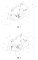
- Fig. 1 is a schematic structural view of a preferred gate device according to the invention when being in the closed state
- Fig. 2 is a schematic view of the gate device in Fig. 1 when being in the opening course state;
- Fig. 3 is a schematic view of the gate in Fig. 1 when being in the completely opened state;
- Fig. 4 is a schematic sectional view of the gate in Fig. 1 when being in the closed state;
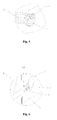
- Fig. 5 is a schematic view of an adjustable rod embracing structure
- Fig. 6 is a partial enlarged schematic view of portion A in Fig. 2 ;
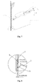
- Fig. 7 is a schematic sectional view of another preferred gate device according to the invention when being in the closed state.
- Fig. 8 is a partial enlarged schematic view of portion B in Fig. 7 .
- the preferred gate device of the cash inlet/outlet 1 applied in the financial self-service instrument includes an integral welded frame 3, a door 2 and a power transmission mechanism.
- the door 2 is of a plate shape.
- One side of the door 2 is installed to the frame 3 through a first rotation shaft 4 and is rotatable around the first rotation shaft 4.
- a pair of shaft seats 21 is fixed on the back surface of the door 2
- the first rotation shaft 4 is fixed to the door 2 through the shaft seats 21.
- Two ends of the first rotation shaft 4 are connected to the frame 3 through a pair of bearings 41.
- the door 2 may be rotated around the axis of the first rotation shaft 4, so as to open or close the cash inlet/outlet 1 of the financial self-service instrument.
- the power transmission mechanism which is fixed on the frame 3.
- the power transmission mechanism includes an electric motor 5, a driving gear 51, a driven gear 52 and a pair of one-way folded connecting rod mechanisms 70.
- the electric motor 5 is fixed on the frame 3, and drives the driving gear 51 to rotate in the clockwise or counterclockwise direction.
- the driven gear 52 is engaged with the driving gear 51, and is rotated in a reverse direction as the driving gear 51 rotates.
- the driven gear 52 is installed on a rotation shaft 6 which is installed on the frame 3 through a pair of bearings 61.
- the driven gear 52 is fixedly connected with the rotation shaft 6.
- the pair of one-way folded connecting rod mechanisms 70 are connected between the rotation shaft 6 and the door 2, and located symmetrically at two ends of the rotation shaft 6.
- each of one-way folded connecting rod mechanisms includes a first connecting rod 71 and a second connecting rod 72.
- One end of the first connecting rod 71 is connected to the door 2 through a rotation shaft 8.
- the rotation shaft 8 is fixed on the back surface of the door 2 through shaft seats 81.
- the rotation shaft 8 is disposed to parallel to the first rotation shaft 4, and located at the other side of the back surface of the door 2 opposite to the rotation shaft 4.
- One end of the second connecting rod 72 is hinged with the other end of the first connecting rod 71 through a shaft 73.
- the end of the second connecting rod 72 adjacent to the first connecting rod 71 is formed into two extending sheets 721.
- the rotation shaft 73 fixedly passes through the two extending sheets 721.
- the first connecting rod 71 is hold between the two extending sheets 721 and is movably provided on the rotation shaft 73.
- the other end of the second connecting rod 72 is fixedly connected to the rotation shaft 6, and is rotated as the rotation shaft 6 rotates. As shown in Fig.
- the second connecting rod 72 and the rotation shaft 6 are designed into a rod embracing structure.
- the end of the second connecting rod 72 may clamp the rotation shaft 6 by adjusting a tightening screw 723.
- Such rod embracing design allows the second connecting rod 72 to be stably and fixedly connected to the rotation shaft 6 and be rotated as the rotation shaft 6 rotates, and may ensure that there is no slip between the second connecting rod 72 and the rotation shaft 6, thereby ensuring that two second connecting rods 72 of the pair of one-way folded connecting rod mechanisms 70 may be synchronously rotated as the rotation shaft 6 rotates.
- the two second connecting rods 72 when being rotated around the axis of the shaft 6, the two second connecting rods 72 may be effectively maintained in parallel, that is, they are not twisted.
- the end of the first connecting rod 71 hinged with the second connecting rod 72 is raised, and thus the other end thereof connected to the rotation shaft 8 is raised, so as to draw the door 2 to rotate around the axis of the first rotation shaft 4, thereby opening the cash inlet/outlet 1 of the financial self-service instrument.
- Fig. 3 a schematic view of the gate when being in the completely opened state is shown, at this moment, the first connecting rod 71 and the second connecting rod 72 are approximately in parallel, and the second connecting rod 72 cannot drive the first connecting rod 71 to rotate in the clockwise direction, that is, the first connecting rod 71 and the second connecting rod are in folded state.
- the electric motor 5 rotates in reverse direction, and drives the driving gear 51 to rotate in the clockwise direction, so that the driven gear 52 is rotated in the counterclockwise direction.
- the rotation shaft 6 and the second connecting rod 72 are rotated in the counterclockwise direction.
- the second connecting rod 72 pushes the first connecting rod 71 to move, and the first connecting rod 71 pushes the door 2 to rotate around the axis of the first rotation shaft 4 in the clockwise direction, thereby closing the door 2.
- Fig. 4 a schematic sectional view of the gate when being in the completely closed state is shown, at this moment, the first connecting rod 71 and the second connecting rod 72 are in an approximate straight state.
- the end of the first connecting rod 71 adjacent to the shaft 73 has an end surface 711
- the second connecting rod 72 has an end surface 722 cooperated with the end surface 711 of the first connecting rod 71.
- the end surface 711 and the end surface 722 butt against with each other, so that the second connecting rod 72 cannot be continuously rotated in the counterclockwise direction, thereby the door 2 being in the closed state.
- the second connecting rod 72 Since the axis of the shaft 73 is positioned below the connecting line between the axis of the shaft 8 and the axis of the shaft 6, the second connecting rod 72 would only be rotated around the axis of the shaft 6 in the counterclockwise direction, so that the first connecting rod 71 have to swing around the axis of the shaft 8 in the clockwise direction.
- the axes of the shaft 8, the shaft 73 and the shaft 6 should be in the same line, or the shaft 73 should be positioned below the connecting line A between the axes of the rotation shaft 8 and the rotation shaft 6. If a connecting line B is assumed between the axis of the shaft 73 and the axis of the rotation shaft 6, a separation angle is formed between the connecting line A and the connecting line B. Thus, since the end surfaces 711, 722 abut against with each other, the first connecting rod 71 cannot be rotated around the shaft 73 in the clockwise direction under the external force F, and thus the door 2 cannot be opened because the first connecting rod 71 cannot be rotated in the clockwise direction.
- the weight P of the connecting rod can be overcome only by the power of internal electric motor. That is, the shaft 6 is rotated and drives the second connecting rod 72 to rotate in the clockwise direction, so that the shaft 73 goes across the connecting line A between the shaft 8 and the shaft 6, and drives the connecting rod 71 to rotate, thereby opening the gate.
- the separation angle between the connecting line A and the connecting line B is 5 degree. Of cause, the separation angle may be any appropriate degree according to an actual requirement, preferably is in the range of 0 to 10 degree.
- a torsion spring 75 is provided on the rotation shaft 8. One end of the torsion spring 75 is fixed in a location groove 712 formed in an upper side surface of the first connecting rod 71, and the other end of the torsion spring 75 is fixed to the shaft seat 81 of the rotation shaft 8.
- the torsion spring 75 provides a force of rotating the first connecting rod 71 around the rotation shaft 8 in the clockwise direction, so that the first connecting rod 71 and the second connecting rod 72 are kept in the locked state when the door 2 is in the closed state.
- the provision of the torsion spring 75 may effectively control the jump of the rotation shaft 73 of the connecting rods 71 and 72 in upward or downward direction caused by the vibrating force from the outer side of the door plate, and prevent self-lock of the one-way folded connecting rod mechanism 70 from failing caused when the jump of the rotation shaft 73 in upward or downward direction goes across the connecting line between the axis of the rotation shaft 74 and the axis of the rotation shaft 6.
- the torsion spring 75 when a person attempts to apply the external force F to rotate the first connecting rod 71 in the counterclockwise direction and open the door 2, it is also necessary to overcome the torsion force of the torsion spring 75 to raise the shaft 73 such that the first connecting rod 71 is rotated in the counterclockwise direction. Therefore, due to the provision of the torsion spring 75, it becomes more impossible to illegally open the door 2 by attempting to rotate the first connecting rod 71 in the counterclockwise direction under the external force F.
- the gate device according to the present invention may be self-locking by the one-way folded connecting rod mechanism, and has a function of preventing the gate device from being violently and illegally opened.
- the one-way folded connecting rod mechanism has a simplified structure and a low cost.
- Figs. 7 and 8 another preferred embodiment is also provided in the present invention. As shown in Fig. 7 , the difference between this embodiment and the embodiment shown in Fig.
- a plurality of POM plastic sphere convex dots 9 are provided at peripheral edges of the front surface of the door 2, wherein the front surface of the door 2 is engagable with a cash inlet/outlet of the financial self-service instrument, and the peripheral edges of the door 2 are engagable with the peripheral edges of the cash inlet/outlet.
- the POM plastic sphere convex dots 9 are arranged and fixed at the peripheral edges of the door plate equidistantly.
- the POM plastic anti-sticking sphere convex dots 9 are in contact with the panel of the financial self-service instrument, and a flow guiding gap is formed between the door 2 and the panel, foreign matters which are larger than the distance between the POM plastic sphere convex dots 9 and the flow guiding gap between the door and the panel cannot be inserted.
- commonly used liquid glues such as 502 and AA do not stick POM plastic and the POM plastic sphere convex dots are in contact with the panel of the financial self-service instrument, the contact area between the door 2 and the panel of the financial self-service instrument may be greatly reduced.
- the liquid when the liquid flows into the financial self-service instrument through the gap between the panel of the financial self-service instrument and the door 2, the liquid may flow through the space between the POM plastic sphere convex dots and the flow guiding gap between the door and the panel, and then flow out via a flow guiding inclined surface 31 (so do the dust and the water). Since remnant glue on the contact surface between the POM plastic anti-sticking sphere convex dots and the panel of the financial self-service instrument doesn't stick the POM plastic, the door may be opened by a torque of the door opening electric motor which is slight larger than the normal torque .
- the provision of the POM plastic sphere convex dots may effectively both prevent foreign matters or liquid from filling into the financial self-service instrument through the gate device by criminals, and prevent the gate device from being damaged with the liquid glues available in the market by criminals, and thus perform a safeguard function.
Landscapes
- Physics & Mathematics (AREA)
- General Physics & Mathematics (AREA)
- Devices For Checking Fares Or Tickets At Control Points (AREA)
- Power-Operated Mechanisms For Wings (AREA)
Abstract
Description
- The present application claims the benefit of priority to Chinese patent application No.
200910193709.7 - The present invention relates to a cash inlet/outlet gate device for financial self-service instruments, and more particularly, to a self-locking gate device.
- At present, the financial self-service instruments are widely used. Independent self-service instruments may provide 24-hour uninterrupted service, so as to provide many advantages to people's lives. Unattended automatic teller machines are convenient to depositors. However, it also provides an opportunity for criminals to steal or intercept money from depositors. As the automatic teller machine is widely installed, criminal cases for the automatic teller machine are also increasing year after year. Such kind of crime mainly includes, i) illegally intercepting money from depositors by taking some actions to the cash outlet; and ii) stealing money from depositors by illegally obtaining information and passwords of bank cards of depositors.
- For the first kind of crime, the financial self-service instrument needs to be equipped with a cash outlet gate which may prevent foreign matters from being inserted, prevent liquid glues, resist a certain violent damage and avoid from being illegally opened. A current cash outlet gate is generally resisted by a gate stopper in order to prevent from being illegally opened. However, in this manner, it is inevitable to form a gap between the gate and a base plate when assembling the gate, and thus criminals may move the gate stopper from the gap with a thin rigid sheet, so that the gate may be easily opened. Obviously, it is an important problem of designing the financial self-service instrument to improve the safety and reliability of the cash outlet gate and prevent the cash outlet gate from being illegally opened.
- The conventional gate locking device generally has many members, and thus has a complex structure. Therefore, it is necessary to provide a self-locking cash outlet gate structure which has a simplified structure and high safety and reliability.
- The object of the invention is to provide a self-locking gate structure which may prevent from being illegally opened.
- The further object of the invention is to provide an anti-inserted foreign matters and anti-liquid glues sticking gate structure.
- In view of the above objects, the present invention provides a self-locking gate device, installed in a financial self-service instrument and configured to open or close a cash inlet/outlet of the financial self-service instrument. The self-locking gate device includes an integral welded frame, a door and a power transmission mechanism. The door is installed on the frame through a first rotation shaft and is rotatable around the first rotation shaft. The power transmission mechanism is fixed on the frame and proving a power for the rotation of the door. The power transmission mechanism includes an electric motor and at least one one-way folded connecting rod mechanism. The one-way folded connecting rod mechanism includes a first connecting rod and a second connecting rod. The first connecting rod and the second connecting rod are hinged together through a second shaft. The other end of the first connecting rod is connected to the door through a third shaft. The third shaft and the first shaft are disposed in parallel and are respectively located at two opposite ends of the door. The other end of the second connecting rod is connected to the electric motor through a fourth shaft. The electric motor drives and rotates the fourth shaft. The second connecting rod and the fourth shaft are fixedly connected together.
- Preferably, an end of the first connecting rod adjacent to the third shaft has a first end surface, and an end of the second connecting rod adjacent to the third shaft has a second end surface. When the cash inlet/outlet of the financial self-service instrument is closed by the door, the first end surface and the second end surface abut against with each other, so as to stop a folding operation formed by rotating the first connecting rod in a clockwise direction and rotating the second connecting rod in a counterclockwise direction.
- Preferably, when the cash inlet/outlet is closed by the door, axes of the second shaft, third shaft and fourth shaft are in the same line, or the second shaft is located below the connecting line A between the axes of the third shaft and the fourth shaft.
- Preferably, in the case that the second shaft is located below the connecting line A between the axes of the third shaft and the fourth shaft and the connecting line between the axes of the second shaft and the fourth shaft is indicated as B, a separation angle formed between A and B is ranged from 0 to 10 degree.
- Preferably, a torsion spring is provided on the third shaft. An end of the torsion spring is fixedly connected to the door, and the other end of the torsion spring is fixedly connected to the first connecting rod. The torsion spring is configured to exert a force to the first connecting rod, so as to urge the first connecting rod to rotate around the third shaft in the clockwise direction.
- Preferably, a rod embracing structure is formed between the second connecting rod and the fourth shaft, and the second connecting rod is configured to clamp the fourth shaft through a screw.
- Preferably, the power transmission mechanism further includes a driving gear and a driven gear engaged with the driving gear, the driven gear is installed on the fourth shaft so as to rotate the fourth shaft.
- Optionally, the power transmission mechanism includes a pair of one-way folded connecting rod mechanisms. The pair of one-way folded connecting rod mechanisms is connected between the door and the fourth shaft, and the pair of one-way folded connecting rod mechanisms is symmetrically located two ends of the fourth shaft.
- In order to further achieve the object of preventing foreign matters from being inserted and preventing liquid glues from sticking, the edges of the door of the self-locking gate device engaged with the cash inlet/outlet of the financial self-service instrument are provided with POM plastic sphere convex dots. Preferably, the POM plastic convex sphere convex dots are distributed uniformly and equidistantly.
- The self-locking gate device according to the present invention has the following advantages.
- The one-way folded connecting rod mechanism is provided in the power transmission mechanism, so as to achieve the self-lock function, which may prevent the gate device from being violently destroyed by criminals. The present invention utilizes the characteristic that liquid glues available in the market don't stick the POM plastic, and the edges of the door engaged with the cash inlet/outlet of the financial self-service instrument are provided with POM plastic sphere convex dots, thus, the flow guiding gap for liquid glues is formed, and guides liquid glues to flow out. Besides, the sphere convex dots may minimize the contact area between the gate structure and the panel of the cash inlet/outlet of the financial self-service instrument, and decrease the destructive degree of glues to the gate device, thereby preventing the gate device from being damaged by glues.
-
Fig. 1 is a schematic structural view of a preferred gate device according to the invention when being in the closed state; -
Fig. 2 is a schematic view of the gate device inFig. 1 when being in the opening course state; -
Fig. 3 is a schematic view of the gate inFig. 1 when being in the completely opened state; -
Fig. 4 is a schematic sectional view of the gate inFig. 1 when being in the closed state; -
Fig. 5 is a schematic view of an adjustable rod embracing structure; -
Fig. 6 is a partial enlarged schematic view of portion A inFig. 2 ; -
Fig. 7 is a schematic sectional view of another preferred gate device according to the invention when being in the closed state; and -
Fig. 8 is a partial enlarged schematic view of portion B inFig. 7 . - Hereinafter, the technical solutions in embodiments of the present invention will be described clearly and completely with reference to drawings of the embodiments of the present invention. It is apparent that the embodiments to be described are merely a portion of embodiments of the present invention, but not all of the embodiments. Based on the embodiments of the present invention, all of other embodiments made by those skilled in the art without inventive effort fall into the protection scope of the present invention.
- Referring to
Figs. 1 to 3 , the preferred gate device of the cash inlet/outlet 1 applied in the financial self-service instrument according to the present invention includes an integral weldedframe 3, adoor 2 and a power transmission mechanism. Thedoor 2 is of a plate shape. One side of thedoor 2 is installed to theframe 3 through afirst rotation shaft 4 and is rotatable around thefirst rotation shaft 4. Specifically, a pair ofshaft seats 21 is fixed on the back surface of thedoor 2, and thefirst rotation shaft 4 is fixed to thedoor 2 through the shaft seats 21. Two ends of thefirst rotation shaft 4 are connected to theframe 3 through a pair ofbearings 41. After being installed, thedoor 2 may be rotated around the axis of thefirst rotation shaft 4, so as to open or close the cash inlet/outlet 1 of the financial self-service instrument. Certainly, the power to rotate thedoor 2 around the axis of thefirst rotation shaft 4 comes from the power transmission mechanism which is fixed on theframe 3. The power transmission mechanism includes anelectric motor 5, adriving gear 51, a drivengear 52 and a pair of one-way folded connectingrod mechanisms 70. Specifically, theelectric motor 5 is fixed on theframe 3, and drives thedriving gear 51 to rotate in the clockwise or counterclockwise direction. The drivengear 52 is engaged with thedriving gear 51, and is rotated in a reverse direction as thedriving gear 51 rotates. The drivengear 52 is installed on arotation shaft 6 which is installed on theframe 3 through a pair ofbearings 61. The drivengear 52 is fixedly connected with therotation shaft 6. When the drivengear 52 is rotated, therotation shaft 6 is rotated synchronously. The pair of one-way folded connectingrod mechanisms 70 are connected between therotation shaft 6 and thedoor 2, and located symmetrically at two ends of therotation shaft 6. Specifically, each of one-way folded connecting rod mechanisms includes a first connectingrod 71 and a second connectingrod 72. One end of the first connectingrod 71 is connected to thedoor 2 through arotation shaft 8. Therotation shaft 8 is fixed on the back surface of thedoor 2 through shaft seats 81. Therotation shaft 8 is disposed to parallel to thefirst rotation shaft 4, and located at the other side of the back surface of thedoor 2 opposite to therotation shaft 4. One end of the second connectingrod 72 is hinged with the other end of the first connectingrod 71 through ashaft 73. Specifically, the end of the second connectingrod 72 adjacent to the first connectingrod 71 is formed into two extendingsheets 721. Therotation shaft 73 fixedly passes through the two extendingsheets 721. The first connectingrod 71 is hold between the two extendingsheets 721 and is movably provided on therotation shaft 73. The other end of the second connectingrod 72 is fixedly connected to therotation shaft 6, and is rotated as therotation shaft 6 rotates. As shown inFig. 5 , the second connectingrod 72 and therotation shaft 6 are designed into a rod embracing structure. When assembling, the end of the second connectingrod 72 may clamp therotation shaft 6 by adjusting a tighteningscrew 723. Such rod embracing design allows the second connectingrod 72 to be stably and fixedly connected to therotation shaft 6 and be rotated as therotation shaft 6 rotates, and may ensure that there is no slip between the second connectingrod 72 and therotation shaft 6, thereby ensuring that two second connectingrods 72 of the pair of one-way folded connectingrod mechanisms 70 may be synchronously rotated as therotation shaft 6 rotates. In this embodiment, when being rotated around the axis of theshaft 6, the two second connectingrods 72 may be effectively maintained in parallel, that is, they are not twisted. - When the
electric motor 5 rotates in the counterclockwise direction as shown inFig. 2 , thedriving gear 51 is rotated in the counterclockwise direction, and thus the drivengear 52 is rotated in the clockwise direction. Thus, therotation shaft 6 and the second connectingrod 72 fixedly connected to therotation shaft 6 are rotated in the clockwise direction. Since the second connectingrod 72 is hinged with the first connectingrod 71 through theshaft 73, the first connectingrod 71 is rotated when the second connectingrod 72 rotates in the clockwise direction. Specifically, the end of the first connectingrod 71 hinged with the second connectingrod 72 is raised, and thus the other end thereof connected to therotation shaft 8 is raised, so as to draw thedoor 2 to rotate around the axis of thefirst rotation shaft 4, thereby opening the cash inlet/outlet 1 of the financial self-service instrument. As shown inFig. 3 , a schematic view of the gate when being in the completely opened state is shown, at this moment, the first connectingrod 71 and the second connectingrod 72 are approximately in parallel, and the second connectingrod 72 cannot drive the first connectingrod 71 to rotate in the clockwise direction, that is, the first connectingrod 71 and the second connecting rod are in folded state. - Correspondingly, when the
door 2 is to be closed, theelectric motor 5 rotates in reverse direction, and drives thedriving gear 51 to rotate in the clockwise direction, so that the drivengear 52 is rotated in the counterclockwise direction. Thus, therotation shaft 6 and the second connectingrod 72 are rotated in the counterclockwise direction. The second connectingrod 72 pushes the first connectingrod 71 to move, and the first connectingrod 71 pushes thedoor 2 to rotate around the axis of thefirst rotation shaft 4 in the clockwise direction, thereby closing thedoor 2. As shown inFig. 4 , a schematic sectional view of the gate when being in the completely closed state is shown, at this moment, the first connectingrod 71 and the second connectingrod 72 are in an approximate straight state. The end of the first connectingrod 71 adjacent to theshaft 73 has anend surface 711, and the second connectingrod 72 has anend surface 722 cooperated with theend surface 711 of the first connectingrod 71. At this moment, as shown inFig. 4 , theend surface 711 and theend surface 722 butt against with each other, so that the second connectingrod 72 cannot be continuously rotated in the counterclockwise direction, thereby thedoor 2 being in the closed state. - At this moment, if the door is pushed by an external force F, the external force F is transmitted to the second connecting
rod 72 through the first connectingrod 71 in a direction of connecting line between the axes of theshaft 8 and theshaft 73. Since the axis of theshaft 73 is positioned below the connecting line between the axis of theshaft 8 and the axis of theshaft 6, the second connectingrod 72 would only be rotated around the axis of theshaft 6 in the counterclockwise direction, so that the first connectingrod 71 have to swing around the axis of theshaft 8 in the clockwise direction. However, the door has been in the closed state, and theend surface 711 of the end of the first connectingrod 71 adjacent to theshaft 73 and theend surface 722 of the end of the second connectingrod 72 adjacent to theshaft 73 have been butted against with each other, so the second connectingrod 72 cannot be rotated around the axis of theshaft 6 in the counterclockwise direction, and the first connectingrod 71 cannot swing around the axis of theshaft 8 in the clockwise direction, thereby achieving the self-locking state of the connectingrod mechanisms 70. Besides, when the external force F is increased, the interaction force between theend surface 711 of the first connectingrod 71 and theend surface 722 of the second connectingrod 72 is also increased, meanwhile, the shearing force exerted to theshaft 73 is also increased, which may effectively prevent the gate device from being illegally opened by the external force F. - As can be known from the above description, in order to prevent the gate device from being illegally opened by an external pushing force, it is necessary to ensure that, when being transmitted through the one-way folded connecting rod mechanism, the external force F cannot generate a component force, at the
shaft 73, which may drive the connectingrod 72 to rotate around theshaft 6 in the clockwise direction. According to the principle of the mechanics transmission, in order to achieve the above object, there is a particular position relationship between theshaft 8, the connectingrod 71, theshaft 73, the connectingrod 72 and theshaft 6, i.e., theshaft 73 cannot be positioned above the connecting line A between the axis of therotation shaft 8 and the axis of therotation shaft 6. That is, the axes of theshaft 8, theshaft 73 and theshaft 6 should be in the same line, or theshaft 73 should be positioned below the connecting line A between the axes of therotation shaft 8 and therotation shaft 6. If a connecting line B is assumed between the axis of theshaft 73 and the axis of therotation shaft 6, a separation angle is formed between the connecting line A and the connecting line B. Thus, since the end surfaces 711, 722 abut against with each other, the first connectingrod 71 cannot be rotated around theshaft 73 in the clockwise direction under the external force F, and thus thedoor 2 cannot be opened because the first connectingrod 71 cannot be rotated in the clockwise direction. If thedoor 2 is to be opened by rotating the first connectingrod 71 around theshaft 73 in the counterclockwise direction, the weight P of the connecting rod can be overcome only by the power of internal electric motor. That is, theshaft 6 is rotated and drives the second connectingrod 72 to rotate in the clockwise direction, so that theshaft 73 goes across the connecting line A between theshaft 8 and theshaft 6, and drives the connectingrod 71 to rotate, thereby opening the gate. In the embodiment, the separation angle between the connecting line A and the connecting line B is 5 degree. Of cause, the separation angle may be any appropriate degree according to an actual requirement, preferably is in the range of 0 to 10 degree. - In addition, in order to further prevent the gate device from being illegally opened, referring to
Fig 6 , atorsion spring 75 is provided on therotation shaft 8. One end of thetorsion spring 75 is fixed in a location groove 712 formed in an upper side surface of the first connectingrod 71, and the other end of thetorsion spring 75 is fixed to theshaft seat 81 of therotation shaft 8. Thetorsion spring 75 provides a force of rotating the first connectingrod 71 around therotation shaft 8 in the clockwise direction, so that the first connectingrod 71 and the second connectingrod 72 are kept in the locked state when thedoor 2 is in the closed state. Therefore, the provision of thetorsion spring 75 may effectively control the jump of therotation shaft 73 of the connectingrods rod mechanism 70 from failing caused when the jump of therotation shaft 73 in upward or downward direction goes across the connecting line between the axis of the rotation shaft 74 and the axis of therotation shaft 6. In other words, when a person attempts to apply the external force F to rotate the first connectingrod 71 in the counterclockwise direction and open thedoor 2, it is also necessary to overcome the torsion force of thetorsion spring 75 to raise theshaft 73 such that the first connectingrod 71 is rotated in the counterclockwise direction. Therefore, due to the provision of thetorsion spring 75, it becomes more impossible to illegally open thedoor 2 by attempting to rotate the first connectingrod 71 in the counterclockwise direction under the external force F. - Therefore, the gate device according to the present invention may be self-locking by the one-way folded connecting rod mechanism, and has a function of preventing the gate device from being violently and illegally opened. Besides, the one-way folded connecting rod mechanism has a simplified structure and a low cost.
- In addition, except for attempts to open the gate by violent force, criminals often take means such as inserting foreign matters or applying liquid glues, so that the gate device works abnormally, in order to obtain an opportunity to destroy the gate device to steal the cash in the financial self-service instrument. In order to prevent the gate device from being inserted foreign matters and filled liquid glues by criminals, referring to
Figs. 7 and 8 , another preferred embodiment is also provided in the present invention. As shown inFig. 7 , the difference between this embodiment and the embodiment shown inFig. 4 lies in that, a plurality of POM plastic sphereconvex dots 9 are provided at peripheral edges of the front surface of thedoor 2, wherein the front surface of thedoor 2 is engagable with a cash inlet/outlet of the financial self-service instrument, and the peripheral edges of thedoor 2 are engagable with the peripheral edges of the cash inlet/outlet. The POM plastic sphereconvex dots 9 are arranged and fixed at the peripheral edges of the door plate equidistantly. When thedoor 2 is in the closed state, the POM plastic anti-sticking sphereconvex dots 9 are in contact with the panel of the financial self-service instrument, and a flow guiding gap is formed between thedoor 2 and the panel, foreign matters which are larger than the distance between the POM plastic sphereconvex dots 9 and the flow guiding gap between the door and the panel cannot be inserted. In addition, since commonly used liquid glues such as 502 and AA do not stick POM plastic and the POM plastic sphere convex dots are in contact with the panel of the financial self-service instrument, the contact area between thedoor 2 and the panel of the financial self-service instrument may be greatly reduced. Thus, referring toFig. 8 , when the liquid flows into the financial self-service instrument through the gap between the panel of the financial self-service instrument and thedoor 2, the liquid may flow through the space between the POM plastic sphere convex dots and the flow guiding gap between the door and the panel, and then flow out via a flow guiding inclined surface 31 (so do the dust and the water). Since remnant glue on the contact surface between the POM plastic anti-sticking sphere convex dots and the panel of the financial self-service instrument doesn't stick the POM plastic, the door may be opened by a torque of the door opening electric motor which is slight larger than the normal torque . Therefore, the provision of the POM plastic sphere convex dots may effectively both prevent foreign matters or liquid from filling into the financial self-service instrument through the gate device by criminals, and prevent the gate device from being damaged with the liquid glues available in the market by criminals, and thus perform a safeguard function. - While the preferred embodiments of the present invention have been described above, it is not intended to limit the protection scope of the present invention. Therefore, various equivalent variations made by those skilled in the art based on the contents described in the Description and illustrated in drawings of the present invention are deemed to fall into the protection scope of the present invention.
Claims (10)
- A self-locking gate device, installed in a financial self-service instrument and configured to open or close a cash inlet/outlet of the financial self-service instrument, wherein the self-locking gate device comprises:an integral welded frame;a door installed on the frame through a first rotation shaft and being rotatable around the first rotation shaft; anda power transmission mechanism fixed on the frame and proving a power for a rotation of the door;wherein the power transmission mechanism comprises an electric motor and at least one one-way folded connecting rod mechanism, the one-way folded connecting rod mechanism comprises a first connecting rod and a second connecting rod, the first connecting rod and the second connecting rod are hinged together through a second shaft, the other end of the first connecting rod is connected to the door through a third shaft, the third shaft and the first shaft are disposed in parallel and are respectively located at two opposite ends of the door, the other end of the second connecting rod is connected to the electric motor through a fourth shaft, the electric motor drives and rotates the fourth shaft, the second connecting rod and the fourth shaft are fixedly connected together.
- The self-locking gate device according to claim 1, wherein an end of the first connecting rod adjacent to the third shaft has a first end surface, and an end of the second connecting rod adjacent to the third shaft has a second end surface, when the cash inlet/outlet of the financial self-service instrument is closed by the door, the first end surface and the second end surface butt against with each other, so as to stop a folding operation formed by rotating the first connecting rod in a clockwise direction and rotating the second connecting rod in a counterclockwise direction.
- The self-locking gate device according to claim 1, wherein when the cash inlet/outlet is closed by the door, axes of the second shaft, third shaft and fourth shaft are in the same line, or the second shaft is located below a connecting line A between the axes of the third shaft and the fourth shaft.
- The self-locking gate device according to claim 3, wherein, in the case that the second shaft is located below the connecting line A between the axes of the third shaft and the fourth shaft and a connecting line between the axes of the second shaft and the fourth shaft is indicated as B, a separation angle formed between A and B is ranged from 0 to 10 degree.
- The self-locking gate device according to claim 1, wherein a torsion spring is provided on the third shaft, an end of the torsion spring is fixedly connected to the door, the other end of the torsion spring is fixedly connected to the first connecting rod, the torsion spring is configured to exert a force to the first connecting rod so as to urge the first connecting rod to rotate around the third shaft in the clockwise direction.
- The self-locking gate device according to claim 1, wherein a rod embracing structure is formed between the second connecting rod and the fourth shaft, and the second connecting rod is configured to clamp the fourth shaft through a screw.
- The self-locking gate device according to claim 1, wherein the power transmission mechanism further comprises a driving gear and a driven gear engaged with the driving gear, the driven gear is installed on the fourth shaft so as to rotate the fourth shaft.
- The self-locking gate device according to claim 1, wherein the power transmission mechanism comprises a pair of one-way folded connecting rod mechanisms, the pair of one-way folded connecting rod mechanisms are connected between the door and the fourth shaft, and the pair of one-way folded connecting rod mechanisms are symmetrically located two ends of the fourth shaft.
- The self-locking gate device according to any of claims 1 to 8, wherein edges of the door engaged with the cash inlet/outlet of the financial self-service instrument are provided with POM plastic sphere convex dots.
- The self-locking gate device according to claim 9, wherein the POM plastic convex sphere convex dots are distributed uniformly and equidistantly.
Applications Claiming Priority (2)
| Application Number | Priority Date | Filing Date | Title |
|---|---|---|---|
| CN2009101937097A CN101840596B (en) | 2009-11-06 | 2009-11-06 | Self-locking gate device |
| PCT/CN2010/077317 WO2011054240A1 (en) | 2009-11-06 | 2010-09-26 | Self-locking type shutter device |
Publications (2)
| Publication Number | Publication Date |
|---|---|
| EP2472480A1 true EP2472480A1 (en) | 2012-07-04 |
| EP2472480A4 EP2472480A4 (en) | 2013-05-08 |
Family
ID=42743951
Family Applications (1)
| Application Number | Title | Priority Date | Filing Date |
|---|---|---|---|
| EP10827854.0A Withdrawn EP2472480A4 (en) | 2009-11-06 | 2010-09-26 | Self-locking type shutter device |
Country Status (5)
| Country | Link |
|---|---|
| US (1) | US8839940B2 (en) |
| EP (1) | EP2472480A4 (en) |
| CN (1) | CN101840596B (en) |
| AU (1) | AU2010314624B2 (en) |
| WO (1) | WO2011054240A1 (en) |
Cited By (1)
| Publication number | Priority date | Publication date | Assignee | Title |
|---|---|---|---|---|
| CN106296985A (en) * | 2016-08-05 | 2017-01-04 | 深圳怡化电脑股份有限公司 | A kind of paper money outlet door structure and bank self-help terminal |
Families Citing this family (18)
| Publication number | Priority date | Publication date | Assignee | Title |
|---|---|---|---|---|
| CN101840596B (en) * | 2009-11-06 | 2012-01-25 | 广州广电运通金融电子股份有限公司 | Self-locking gate device |
| CN102289862B (en) | 2011-08-17 | 2013-06-26 | 广州广电运通金融电子股份有限公司 | Gate mechanism |
| US10467843B1 (en) * | 2014-08-06 | 2019-11-05 | Wells Fargo Bank, N.A. | Cash counter recycling apparatus and methods |
| CN106408757B (en) * | 2014-12-18 | 2018-10-23 | 浙江众合科技股份有限公司 | A kind of valve system of self-service device terminal |
| US10769878B2 (en) * | 2015-06-14 | 2020-09-08 | Diebold Nixdorf, Incorporated | Fascia gate separable gear drive |
| CN105303692A (en) * | 2015-10-12 | 2016-02-03 | 新达通科技股份有限公司 | Bill outlet bill discharging and withdrawing device |
| US10641029B2 (en) * | 2016-06-29 | 2020-05-05 | S Wiley Consulting, Llc. | Door control system and methods of operating the same |
| CN106340126A (en) * | 2016-08-30 | 2017-01-18 | 广州联业商用机器人科技股份有限公司 | Cargo discharge device and intelligent vending robot with same |
| CN106384132B (en) * | 2016-09-14 | 2023-05-02 | 浙江维融电子科技股份有限公司 | Ukey issuing device and gate device thereof |
| CN107654513B (en) * | 2017-08-04 | 2023-10-20 | 深圳怡化电脑股份有限公司 | Wheel train positioning mechanism and self-service financial equipment |
| CN109993903B (en) * | 2017-12-29 | 2024-01-30 | 山东新北洋信息技术股份有限公司 | Driving device, goods bucket and vending machine |
| CN109048476B (en) * | 2018-08-31 | 2024-03-19 | 宁夏共享机床辅机有限公司 | Lathe helping hand connecting rod formula lift protection translation upturning door |
| CN109519074B (en) * | 2018-12-25 | 2024-02-23 | 江苏国光信息产业股份有限公司 | Binding module with flat-pushing mechanical self-locking gate plate |
| DE102019125994A1 (en) * | 2019-09-26 | 2021-04-01 | Wincor Nixdorf International Gmbh | Device for handling notes of value |
| CN110867544B (en) * | 2019-10-28 | 2022-03-25 | 广东博智林机器人有限公司 | Delivery mechanism and battery replacing robot adopting same |
| CN111870063B (en) * | 2020-08-10 | 2025-07-25 | 山东方霖铝业科技有限公司 | Cabinet for TV |
| CN115749484B (en) * | 2021-09-02 | 2025-10-14 | 北京有竹居网络技术有限公司 | Storage equipment |
| CN119933481B (en) * | 2025-01-03 | 2025-10-03 | 宁波方太厨具有限公司 | Door body structure and cooking device |
Family Cites Families (20)
| Publication number | Priority date | Publication date | Assignee | Title |
|---|---|---|---|---|
| US2813712A (en) * | 1953-09-30 | 1957-11-19 | Studebaker Packard Corp | Rubber bumpers |
| US4889175A (en) * | 1988-03-22 | 1989-12-26 | Excel Industries, Inc. | Torque window |
| US5454332A (en) * | 1993-09-15 | 1995-10-03 | Digital Equipment Corporation | Cash pocket for an automatic teller machine |
| FR2733420B1 (en) | 1995-04-28 | 1997-06-27 | Sep Tarral | PECTIC PREPARATIONS FOR USE AS MEDICINAL MEDIA |
| CN1174157C (en) * | 1996-11-27 | 2004-11-03 | 英脱布尔特 | Secure enclosure bolt assembly for automated banking machine |
| IT1311191B1 (en) * | 1999-12-09 | 2002-03-04 | Carlo Pedemonte | ARTICULATED ACTUATOR FOR GATES, DOORS AND SIMILAR. |
| US6857166B2 (en) * | 2001-11-13 | 2005-02-22 | Toyoda Gosei Co., Ltd. | Cushion |
| KR100746921B1 (en) * | 2001-12-24 | 2007-08-08 | 엘지엔시스(주) | Inlet opening and closing device of sealed box for unmanned automation equipment |
| KR100425867B1 (en) * | 2001-12-29 | 2004-04-01 | 엘지엔시스(주) | Apparatus for dispensing cash in automatic teller machine |
| US7052048B2 (en) * | 2002-08-30 | 2006-05-30 | Paragon Aquatics, A Division Of Pentair Pool Products, Inc. | Through flange |
| US20040245328A1 (en) * | 2003-06-05 | 2004-12-09 | Schaper Patrick A. | Door-in-door newspaper box cover |
| US8169169B2 (en) * | 2005-04-13 | 2012-05-01 | Brian Hass | Door operator for controlling a door and method of same |
| CN101278011B (en) * | 2005-08-02 | 2012-10-24 | 环球产权公司 | Silicone compositions, methods of manufacture, and articles formed therefrom |
| US8052041B2 (en) * | 2006-11-10 | 2011-11-08 | Diebold Self-Service Systems Division Of Diebold, Incorporated | Method of operation of card activated automated banking machine |
| WO2008111148A1 (en) | 2007-03-12 | 2008-09-18 | Glory Ltd. | Shutter device |
| US7774984B2 (en) * | 2007-07-27 | 2010-08-17 | Eledyna Technology Corporation | Concentric cross mechanism for transiting torsion |
| JP2009035911A (en) * | 2007-08-01 | 2009-02-19 | Hitachi Omron Terminal Solutions Corp | Enclosure door lock mechanism of electronic equipment |
| JP5174469B2 (en) * | 2008-01-11 | 2013-04-03 | 日立オムロンターミナルソリューションズ株式会社 | External shutter mechanism and automatic cash transaction device |
| CN101840596B (en) * | 2009-11-06 | 2012-01-25 | 广州广电运通金融电子股份有限公司 | Self-locking gate device |
| CN101840595B (en) * | 2009-11-06 | 2012-05-16 | 广州广电运通金融电子股份有限公司 | Financial self-service equipment for preventing foreign substance blockage and sticky destruction |
-
2009
- 2009-11-06 CN CN2009101937097A patent/CN101840596B/en active Active
-
2010
- 2010-09-26 AU AU2010314624A patent/AU2010314624B2/en not_active Ceased
- 2010-09-26 EP EP10827854.0A patent/EP2472480A4/en not_active Withdrawn
- 2010-09-26 WO PCT/CN2010/077317 patent/WO2011054240A1/en not_active Ceased
- 2010-09-26 US US13/500,275 patent/US8839940B2/en not_active Expired - Fee Related
Cited By (1)
| Publication number | Priority date | Publication date | Assignee | Title |
|---|---|---|---|---|
| CN106296985A (en) * | 2016-08-05 | 2017-01-04 | 深圳怡化电脑股份有限公司 | A kind of paper money outlet door structure and bank self-help terminal |
Also Published As
| Publication number | Publication date |
|---|---|
| WO2011054240A1 (en) | 2011-05-12 |
| AU2010314624B2 (en) | 2014-07-24 |
| CN101840596B (en) | 2012-01-25 |
| US8839940B2 (en) | 2014-09-23 |
| US20120192771A1 (en) | 2012-08-02 |
| CN101840596A (en) | 2010-09-22 |
| AU2010314624A1 (en) | 2012-05-10 |
| EP2472480A4 (en) | 2013-05-08 |
Similar Documents
| Publication | Publication Date | Title |
|---|---|---|
| US8839940B2 (en) | Self-locking type shutter device | |
| EP2472479B1 (en) | Financial self-help service device for preventing plugging by foreign objects and damage by mucilage glue | |
| US8919525B2 (en) | Gate mechanism | |
| US8833537B2 (en) | Medium stocking apparatus | |
| AU2014373179B2 (en) | Paper currency accommodating device | |
| US20170233202A1 (en) | Rotary paper money conveying device | |
| KR20110051242A (en) | Cash automatic trading device | |
| US20050284925A1 (en) | Shutter mechanism of automated-teller machine | |
| CN103021095A (en) | Automatic trading device | |
| WO2017020633A1 (en) | Thickness detection device for sheet medium and financial self-service device | |
| US20150314977A1 (en) | Medium handover device and medium processing device | |
| AU2014273775B2 (en) | Binding medium clamping mechanism and banknote binding machine containing same | |
| JP4641776B2 (en) | Shutter mechanism and automatic transaction apparatus | |
| JP5729117B2 (en) | Automation equipment | |
| US20180012436A1 (en) | Dispenser shutter assembly for an automated teller machine | |
| EP3664051B1 (en) | Automated teller machine having bill stopper | |
| KR200287627Y1 (en) | ATM with bars for holding paper money | |
| JP2005141618A (en) | Shutter structure | |
| CN212271862U (en) | Anti-disengaging door lock structure, cabinet and financial equipment | |
| CN103714619A (en) | Rotary device | |
| HK1238400A1 (en) | Rotary paper money conveying device | |
| JPH04233687A (en) | Transacting port mechanism for paper money processor | |
| BR112018077502B1 (en) | IMPLEMENTATION OF FEED WHEEL AND CONTACT SEPARATOR |
Legal Events
| Date | Code | Title | Description |
|---|---|---|---|
| PUAI | Public reference made under article 153(3) epc to a published international application that has entered the european phase |
Free format text: ORIGINAL CODE: 0009012 |
|
| 17P | Request for examination filed |
Effective date: 20120329 |
|
| AK | Designated contracting states |
Kind code of ref document: A1 Designated state(s): AL AT BE BG CH CY CZ DE DK EE ES FI FR GB GR HR HU IE IS IT LI LT LU LV MC MK MT NL NO PL PT RO SE SI SK SM TR |
|
| DAX | Request for extension of the european patent (deleted) | ||
| A4 | Supplementary search report drawn up and despatched |
Effective date: 20130408 |
|
| RIC1 | Information provided on ipc code assigned before grant |
Ipc: G07D 11/00 20060101AFI20130402BHEP |
|
| 17Q | First examination report despatched |
Effective date: 20151105 |
|
| GRAP | Despatch of communication of intention to grant a patent |
Free format text: ORIGINAL CODE: EPIDOSNIGR1 |
|
| INTG | Intention to grant announced |
Effective date: 20191011 |
|
| STAA | Information on the status of an ep patent application or granted ep patent |
Free format text: STATUS: THE APPLICATION IS DEEMED TO BE WITHDRAWN |
|
| 18D | Application deemed to be withdrawn |
Effective date: 20200222 |