JP2009035911A - Casing door locking mechanism for electronic device - Google Patents
Casing door locking mechanism for electronic device Download PDFInfo
- Publication number
- JP2009035911A JP2009035911A JP2007200297A JP2007200297A JP2009035911A JP 2009035911 A JP2009035911 A JP 2009035911A JP 2007200297 A JP2007200297 A JP 2007200297A JP 2007200297 A JP2007200297 A JP 2007200297A JP 2009035911 A JP2009035911 A JP 2009035911A
- Authority
- JP
- Japan
- Prior art keywords
- door
- lock
- locking mechanism
- link
- housing
- Prior art date
- Legal status (The legal status is an assumption and is not a legal conclusion. Google has not performed a legal analysis and makes no representation as to the accuracy of the status listed.)
- Pending
Links
Images


Abstract
Description
本発明は、電子機器装置の扉において、扉に対するこじ開け攻撃に対し閂がリンク機構に連動しないことにより、全ての閂のロック解除を必要とする防犯性を高めた筐体のロック機構に関する。 The present invention relates to a case locking mechanism for a casing of an electronic device apparatus, which has an improved crime prevention function that requires unlocking of all the hooks by preventing the hooks from interlocking with a link mechanism against a pricking attack against the door.
防犯性を必要とする電子機器装置の扉は、扉のロック構造の閂の本数を多くしたり、閂の径を太くしたりすることにより一見強固な防犯性を有しているように見えるが、実際はリンクにより複数のロックシャフトは連動しており、一つのロックシャフトを攻撃すれば、扉は開けることが可能であった。そのような扉を攻撃する盗難に対し長時間の防犯性を有する電子機器装置の筐体のロック機構が必要であった。 The doors of electronic devices that require crime prevention seem to have strong crime prevention at first glance by increasing the number of hooks in the door lock structure or increasing the diameter of the hooks. In fact, a plurality of lock shafts are linked by a link, and if one lock shaft is attacked, the door can be opened. There has been a need for a lock mechanism for a casing of an electronic device that has a long-term security against a theft that attacks such a door.
前記従来例によれば、電子機器装置の筐体の扉ロック機構は一見、防犯性が高いようにみえるが、閂による扉ロック機構は携帯電動工具等による扉への攻撃で全ての閂とリンク機構が連結しているため、複数ある閂のうち一ヶ所の閂を外部からロック解除方向に力を加え、ロック解除されると、連結されている全ての閂がロック解除され、他の閂を攻撃されることなく短時間で扉を開けることができてしまうという課題が生じる。 According to the conventional example, the door lock mechanism of the housing of the electronic device device seems to be high in crime prevention. However, the door lock mechanism by the heel links to all the heels by attacking the door with a portable electric tool or the like. Since the mechanism is connected, when one of the multiple hooks is applied in the unlocking direction from the outside and unlocked, all the connected hooks are unlocked and other hooks There arises a problem that the door can be opened in a short time without being attacked.
本発明の目的は、錠の回転による扉の開閉の機構を保持しつつ、外部からの携帯電動工具等による扉への攻撃に対し扉ロック機構を独立させ、全ての閂のロック解除を行う時間を稼ぎ防犯性の高い電子機器装置を提供することにある。 The object of the present invention is to hold the mechanism for opening and closing the door by rotating the lock, and to make the door lock mechanism independent from attacks on the door by a portable electric tool or the like from the outside, and to unlock all the bags. It is to provide an electronic device apparatus that has high crime prevention performance.
筐体と、開閉扉と、錠と、筐体に嵌合し扉を閉状態にロックする閂と、ロック開閉のため錠と閂を連動させるリンク機構からなる電子機器装置において、閂とリンク機構との間に常に閂を開閉方向にスライド可能に構成した連結板を設け、携帯電動工具等による扉への攻撃に対して独立して閂のロック解除を行い、扉が開くためには全ての閂のロック解除を必要とするように構成したことにある。 In an electronic device apparatus comprising a housing, an opening / closing door, a lock, a hook that fits into the housing and locks the door in a closed state, and a link mechanism that interlocks the lock and the hook for opening and closing the lock, the hook and the link mechanism In order to open the door, all the doors must be unlocked independently and the door can be unlocked independently of attacks on the door by a portable power tool. It is in the configuration that requires unlocking of the bag.
上述のような構成としたので鍵の回転による扉の開閉には一度で全ての閂がリンク機構に連動し扉が開閉するのに対し、外部からの携帯電動工具等による扉への攻撃には常に閂を閉方向に作用するように構成した事により、全ての閂を攻撃しロック解除なければ扉が開閉しないため時間稼ぎができ防犯性の高い機構とした。 Because it is configured as described above, when the door is opened and closed by rotating the key, all the hooks are linked to the link mechanism to open and close the door at once. By constructing it so that it always acts in the closing direction, the door does not open and close unless all the swords are attacked and unlocked, making it possible to earn time and to have a high crime prevention mechanism.
本発明によれば外部からの携帯電動工具等による扉への攻撃に対し閂を独立させることにより全ての閂のロック解除を行う時間を稼ぐことができる防犯性の高い電子機器装置を提供することができる。 According to the present invention, it is possible to provide an electronic device device with high security that can earn time for unlocking all the bags by making the bags independent from attacks on the door by a portable electric tool or the like from the outside. Can do.
以下、図1から図8を参照して、本開発の一実施形態を説明する。本実施形態は、金庫や金融機関システムに採用される例えばATM(Automatated Teller Machine)のような電子機器装置に関する。 Hereinafter, an embodiment of the present development will be described with reference to FIGS. The present embodiment relates to an electronic apparatus device such as an ATM (Automatated Teller Machine) employed in a safe or a financial institution system.
先ず図1は、本実施形態に係る筐体本体部1と筐体扉部2をあわせた電子機器装置の外観図であり、図2は図1の筐体扉部2を開けた外観図である。図3は筐体扉部2についているロック機構3の外観図であり、図4は図3のロック機構3の詳細図であり、外観図を用いて、概略構造を説明する。
First, FIG. 1 is an external view of an electronic apparatus device in which a
電子機器装置は、金融機関等に設置され、現金の保管や入金、出金等の取引を行う電子機器装置であり、従来電子機器装置は、筐体本体部1と筐体扉部2からなり、筐体扉部2はロック機構3を設け、筐体本体部1には嵌合穴16が設けられ、ロック機構3のロックシャフト7がその嵌合穴16に入り込むことにより筐体扉部2を閉状態でロックする装置である。筐体扉部2は、錠15を解除方向に回転させることによりロック機構3を作動させ、筐体扉部2を開けることができるが、錠15を回転させないで、筐体扉部2を開けようとした場合には、ロックシャフト7が嵌合穴16に入り込んでいることにより、筐体扉部2を開方向に引いても開けることはできない。筐体扉部2を開けようとする場合には、錠15を回転させ、ロック機構3が作動し、ロックシャフト7が本体側の嵌合穴16から外れ、筐体扉部2を開けることができる。
An electronic device is an electronic device that is installed in a financial institution and performs transactions such as cash storage, deposit, withdrawal, etc. The conventional electronic device is composed of a
扉自体には、錠15があり、錠15には、鍵金具18が取付けられ、錠15の回転と共に回転する。
The door itself has a
鍵金具18はリンク11に連結され、リンク11のもう一端はレバー5と連結されている。
The
リンクの伝達順序としては、錠15を上方向に回転→鍵金具18が回転→リンク11が上下する→レバー5が回転→ロックシャフト7が嵌合穴16から外れる、となり、ロックシャフト7が外れた状態が図5である。
The link transmission order is as follows: the
従来のようなロック機構3に携帯電動工具等による扉への攻撃が加えられた場合、ロックシャフト7が矢印方向へ進み連結しているレバー5が回転し、リンク11が上下することで他のロックシャフト7が嵌合穴16から外れ扉が開く。
When an attack to the door by a portable electric tool or the like is applied to the
図4ではロックシャフト7とレバー5が直接連結している従来のものと違い、レバー5とロックシャフト7の間に連結板6をレバー5側のピンとロックシャフト7側のピン12で固定している構造になっている。
In FIG. 4, unlike the conventional one in which the
図5は錠15を回転させ、リンク11と連結している全てのロックシャフト7を嵌合穴16から外し扉開時にした状態図である。連結板6がロックシャフト7を引く形でロックシャフト7を嵌合穴16から外す為、図5のロックシャフト7とレバー8が直接連結しているロック機構3同様の機構となる。
FIG. 5 is a state diagram in which the
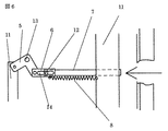
図6は矢印方向から携帯電動工具等による攻撃を筐体扉部2が受けている図であり、ロックシャフト7に組み付けたピン12を連結板6の連結板ガイド穴14に通して水平移動できるようにし、ロックシャフト7に取付けたバネ8が矢印方向に引っ張られることにより、解除方向に進むロックシャフト7を止める。矢印方向からの力でロックシャフト7が水平方向に進むが連結板6によりリンク11に力が伝わらず、他のロックシャフト7に影響がない独立した構成になっている。
FIG. 6 is a view in which the
図7はリンク11の最下部にロックシャフト7を付けた図である。それぞれのロックシャフト7にロックが半がかり状態になることを半ロック状態といい、その半ロック状態を防ぐためにリンク11の最下部にロックシャフト7を直接下方向につけ、筐体本体部1の下部に本体部ロックシャフト受け板9を作り、その嵌合穴16にロックシャフト7が入り込めないことで筐体扉部2が半ロック状態のまま完全に閉じることを防ぐ。
FIG. 7 is a view in which the
図8はロック機構3に閂定位置検知センサを付けた図である。携帯電動工具等による扉への攻撃に対して一つのロックシャフト7がロック解除された場合、他のロックシャフト7は嵌合穴16に入りこんでおり、外部からはロック解除されているか分からないため、そこで閂定位置検知センサ17をロックシャフト近くに配置し、ピン12に当てることにより半ロック状態になった場合、閂定位置検知センサが作動し、半ロック状態のまま筐体扉部2が閉じることを検知する。
FIG. 8 is a view in which a fixed position detection sensor is attached to the
図1から図8では錠15を回転させ、リンク機構3が連動し筐体扉部2を開けたが、ハンドルを回転させることでリンク機構3を連動させても可とする。
1 to 8, the
1…筐体本体部、2…筐体扉部、3…ロック機構、4…閂ロック部構造、5…レバー、6…連結板、7…ロックシャフト、8…バネ、9…本体部ロックシャフト受け板、10…扉部ロックシャフト案内板、11…リンク、12…ピン、13…レバー支点、14…連結板ガイド穴、15…錠、16…嵌合穴、17…閂定位置検知センサ、18…錠金具。
DESCRIPTION OF
Claims (3)
Priority Applications (1)
| Application Number | Priority Date | Filing Date | Title |
|---|---|---|---|
| JP2007200297A JP2009035911A (en) | 2007-08-01 | 2007-08-01 | Casing door locking mechanism for electronic device |
Applications Claiming Priority (1)
| Application Number | Priority Date | Filing Date | Title |
|---|---|---|---|
| JP2007200297A JP2009035911A (en) | 2007-08-01 | 2007-08-01 | Casing door locking mechanism for electronic device |
Publications (1)
| Publication Number | Publication Date |
|---|---|
| JP2009035911A true JP2009035911A (en) | 2009-02-19 |
Family
ID=40438067
Family Applications (1)
| Application Number | Title | Priority Date | Filing Date |
|---|---|---|---|
| JP2007200297A Pending JP2009035911A (en) | 2007-08-01 | 2007-08-01 | Casing door locking mechanism for electronic device |
Country Status (1)
| Country | Link |
|---|---|
| JP (1) | JP2009035911A (en) |
Cited By (6)
| Publication number | Priority date | Publication date | Assignee | Title |
|---|---|---|---|---|
| WO2011054240A1 (en) * | 2009-11-06 | 2011-05-12 | 广州广电运通金融电子股份有限公司 | Self-locking type shutter device |
| WO2015002036A1 (en) * | 2013-07-03 | 2015-01-08 | Necプラットフォームズ株式会社 | Door locking device and electronic equipment |
| US9708839B2 (en) * | 2014-02-24 | 2017-07-18 | Nec Platforms, Ltd. | Casing device and electronic apparatus |
| CN107386493A (en) * | 2017-07-31 | 2017-11-24 | 重庆志谋科技有限公司 | A kind of light cellular partition board |
| CN113345176A (en) * | 2021-08-05 | 2021-09-03 | 恒银金融科技股份有限公司 | Double-door structure for self-service equipment |
| CN114412297A (en) * | 2022-02-07 | 2022-04-29 | 东屋世安物联科技(江苏)股份有限公司 | Two-lock one-open locking mechanism and locking device thereof |
-
2007
- 2007-08-01 JP JP2007200297A patent/JP2009035911A/en active Pending
Cited By (12)
| Publication number | Priority date | Publication date | Assignee | Title |
|---|---|---|---|---|
| WO2011054240A1 (en) * | 2009-11-06 | 2011-05-12 | 广州广电运通金融电子股份有限公司 | Self-locking type shutter device |
| CN101840596B (en) * | 2009-11-06 | 2012-01-25 | 广州广电运通金融电子股份有限公司 | Self-locking gate device |
| US8839940B2 (en) | 2009-11-06 | 2014-09-23 | Grg Banking Equipment Co., Ltd. | Self-locking type shutter device |
| WO2015002036A1 (en) * | 2013-07-03 | 2015-01-08 | Necプラットフォームズ株式会社 | Door locking device and electronic equipment |
| CN105339571A (en) * | 2013-07-03 | 2016-02-17 | Nec平台株式会社 | Door locking device and electronic equipment |
| CN105339571B (en) * | 2013-07-03 | 2017-04-19 | Nec平台株式会社 | Door locking device and electronic equipment |
| US9995068B2 (en) | 2013-07-03 | 2018-06-12 | Nec Platforms, Ltd. | Casing device and electronic equipment |
| US9708839B2 (en) * | 2014-02-24 | 2017-07-18 | Nec Platforms, Ltd. | Casing device and electronic apparatus |
| CN107386493A (en) * | 2017-07-31 | 2017-11-24 | 重庆志谋科技有限公司 | A kind of light cellular partition board |
| CN113345176A (en) * | 2021-08-05 | 2021-09-03 | 恒银金融科技股份有限公司 | Double-door structure for self-service equipment |
| CN114412297A (en) * | 2022-02-07 | 2022-04-29 | 东屋世安物联科技(江苏)股份有限公司 | Two-lock one-open locking mechanism and locking device thereof |
| CN114412297B (en) * | 2022-02-07 | 2023-02-03 | 东屋世安物联科技(江苏)股份有限公司 | Two-lock one-open locking mechanism and locking device thereof |
Similar Documents
| Publication | Publication Date | Title |
|---|---|---|
| CN106088849B (en) | A kind of cam lock | |
| JP2009035911A (en) | Casing door locking mechanism for electronic device | |
| US9359805B2 (en) | Security safe and self-service terminal provided with same | |
| KR200452304Y1 (en) | Door lock having hook | |
| CN104074428B (en) | With springlock and the condom of key lock | |
| CN101781953A (en) | Staple bolt type door lock locking mechanism | |
| JP2005267130A (en) | Automatic cash transaction device | |
| RU2520930C2 (en) | Security lock | |
| KR101305019B1 (en) | Door locking apparatus and keeping apparatus using the same | |
| KR20140002186U (en) | striker for push pull type door lock | |
| CN205976801U (en) | Cam lock | |
| EP2171184B1 (en) | Lock for reinforced doors and the like | |
| KR20140064346A (en) | Interlocking door-lock | |
| KR101372371B1 (en) | Door locking apparatus and keeping apparatus using the same | |
| CN109790726B (en) | Lock box and safety door | |
| JP2001145763A (en) | Locking system of game machine | |
| KR100869609B1 (en) | Door locking structure | |
| JP4978279B2 (en) | Vending machine door lock device | |
| US11619068B2 (en) | Lock | |
| KR20180028713A (en) | Mortise lock | |
| KR101248230B1 (en) | Door locking apparatus and keeping apparatus using the same | |
| KR100716755B1 (en) | Structure for locking of door | |
| KR101127548B1 (en) | Locking apparatus for Door lock and digital door lock having the same | |
| CN105844794A (en) | Coin recycling box with opening double-lock-control function | |
| KR20220105943A (en) | Side door latch device for fire engine |