EP2472130A1 - Connector element - Google Patents
Connector element Download PDFInfo
- Publication number
- EP2472130A1 EP2472130A1 EP12001828A EP12001828A EP2472130A1 EP 2472130 A1 EP2472130 A1 EP 2472130A1 EP 12001828 A EP12001828 A EP 12001828A EP 12001828 A EP12001828 A EP 12001828A EP 2472130 A1 EP2472130 A1 EP 2472130A1
- Authority
- EP
- European Patent Office
- Prior art keywords
- rail
- leg
- connector
- connector element
- legs
- Prior art date
- Legal status (The legal status is an assumption and is not a legal conclusion. Google has not performed a legal analysis and makes no representation as to the accuracy of the status listed.)
- Withdrawn
Links
- 238000003780 insertion Methods 0.000 description 8
- 230000037431 insertion Effects 0.000 description 8
- 230000008719 thickening Effects 0.000 description 6
- 229910052782 aluminium Inorganic materials 0.000 description 3
- XAGFODPZIPBFFR-UHFFFAOYSA-N aluminium Chemical compound [Al] XAGFODPZIPBFFR-UHFFFAOYSA-N 0.000 description 3
- 230000015572 biosynthetic process Effects 0.000 description 3
- 238000010276 construction Methods 0.000 description 3
- 230000000694 effects Effects 0.000 description 3
- 239000000463 material Substances 0.000 description 3
- HCHKCACWOHOZIP-UHFFFAOYSA-N Zinc Chemical compound [Zn] HCHKCACWOHOZIP-UHFFFAOYSA-N 0.000 description 2
- 229910052751 metal Inorganic materials 0.000 description 2
- 239000002184 metal Substances 0.000 description 2
- 229910052725 zinc Inorganic materials 0.000 description 2
- 239000011701 zinc Substances 0.000 description 2
- AZDRQVAHHNSJOQ-UHFFFAOYSA-N alumane Chemical group [AlH3] AZDRQVAHHNSJOQ-UHFFFAOYSA-N 0.000 description 1
- 230000001419 dependent effect Effects 0.000 description 1
- 238000004512 die casting Methods 0.000 description 1
- 238000009434 installation Methods 0.000 description 1
- 238000004519 manufacturing process Methods 0.000 description 1
- 230000000087 stabilizing effect Effects 0.000 description 1
- 229910001220 stainless steel Inorganic materials 0.000 description 1
- 239000010935 stainless steel Substances 0.000 description 1
Images


Classifications
-
- F—MECHANICAL ENGINEERING; LIGHTING; HEATING; WEAPONS; BLASTING
- F16—ENGINEERING ELEMENTS AND UNITS; GENERAL MEASURES FOR PRODUCING AND MAINTAINING EFFECTIVE FUNCTIONING OF MACHINES OR INSTALLATIONS; THERMAL INSULATION IN GENERAL
- F16B—DEVICES FOR FASTENING OR SECURING CONSTRUCTIONAL ELEMENTS OR MACHINE PARTS TOGETHER, e.g. NAILS, BOLTS, CIRCLIPS, CLAMPS, CLIPS OR WEDGES; JOINTS OR JOINTING
- F16B37/00—Nuts or like thread-engaging members
- F16B37/04—Devices for fastening nuts to surfaces, e.g. sheets, plates
- F16B37/045—Devices for fastening nuts to surfaces, e.g. sheets, plates specially adapted for fastening in channels, e.g. sliding bolts, channel nuts
-
- F—MECHANICAL ENGINEERING; LIGHTING; HEATING; WEAPONS; BLASTING
- F16—ENGINEERING ELEMENTS AND UNITS; GENERAL MEASURES FOR PRODUCING AND MAINTAINING EFFECTIVE FUNCTIONING OF MACHINES OR INSTALLATIONS; THERMAL INSULATION IN GENERAL
- F16B—DEVICES FOR FASTENING OR SECURING CONSTRUCTIONAL ELEMENTS OR MACHINE PARTS TOGETHER, e.g. NAILS, BOLTS, CIRCLIPS, CLAMPS, CLIPS OR WEDGES; JOINTS OR JOINTING
- F16B7/00—Connections of rods or tubes, e.g. of non-circular section, mutually, including resilient connections
- F16B7/04—Clamping or clipping connections
- F16B7/044—Clamping or clipping connections for rods or tubes being in angled relationship
- F16B7/0446—Clamping or clipping connections for rods or tubes being in angled relationship for tubes using the innerside thereof
- F16B7/0473—Clamping or clipping connections for rods or tubes being in angled relationship for tubes using the innerside thereof with hook-like parts gripping, e.g. by expanding, behind the flanges of a profile
-
- F—MECHANICAL ENGINEERING; LIGHTING; HEATING; WEAPONS; BLASTING
- F24—HEATING; RANGES; VENTILATING
- F24S—SOLAR HEAT COLLECTORS; SOLAR HEAT SYSTEMS
- F24S25/00—Arrangement of stationary mountings or supports for solar heat collector modules
- F24S25/10—Arrangement of stationary mountings or supports for solar heat collector modules extending in directions away from a supporting surface
- F24S25/13—Profile arrangements, e.g. trusses
-
- F—MECHANICAL ENGINEERING; LIGHTING; HEATING; WEAPONS; BLASTING
- F24—HEATING; RANGES; VENTILATING
- F24S—SOLAR HEAT COLLECTORS; SOLAR HEAT SYSTEMS
- F24S25/00—Arrangement of stationary mountings or supports for solar heat collector modules
- F24S25/60—Fixation means, e.g. fasteners, specially adapted for supporting solar heat collector modules
- F24S25/65—Fixation means, e.g. fasteners, specially adapted for supporting solar heat collector modules for coupling adjacent supporting elements, e.g. for connecting profiles together
-
- E—FIXED CONSTRUCTIONS
- E04—BUILDING
- E04B—GENERAL BUILDING CONSTRUCTIONS; WALLS, e.g. PARTITIONS; ROOFS; FLOORS; CEILINGS; INSULATION OR OTHER PROTECTION OF BUILDINGS
- E04B1/00—Constructions in general; Structures which are not restricted either to walls, e.g. partitions, or floors or ceilings or roofs
- E04B1/38—Connections for building structures in general
- E04B1/58—Connections for building structures in general of bar-shaped building elements
- E04B2001/5868—Hinged connections
-
- E—FIXED CONSTRUCTIONS
- E04—BUILDING
- E04B—GENERAL BUILDING CONSTRUCTIONS; WALLS, e.g. PARTITIONS; ROOFS; FLOORS; CEILINGS; INSULATION OR OTHER PROTECTION OF BUILDINGS
- E04B1/00—Constructions in general; Structures which are not restricted either to walls, e.g. partitions, or floors or ceilings or roofs
- E04B1/38—Connections for building structures in general
- E04B1/58—Connections for building structures in general of bar-shaped building elements
- E04B2001/5881—Connections for building structures in general of bar-shaped building elements using an undercut groove, e.g. dovetail groove
-
- E—FIXED CONSTRUCTIONS
- E05—LOCKS; KEYS; WINDOW OR DOOR FITTINGS; SAFES
- E05D—HINGES OR SUSPENSION DEVICES FOR DOORS, WINDOWS OR WINGS
- E05D11/00—Additional features or accessories of hinges
- E05D11/10—Devices for preventing movement between relatively-movable hinge parts
- E05D11/1007—Devices for preventing movement between relatively-movable hinge parts with positive locking
-
- E—FIXED CONSTRUCTIONS
- E05—LOCKS; KEYS; WINDOW OR DOOR FITTINGS; SAFES
- E05D—HINGES OR SUSPENSION DEVICES FOR DOORS, WINDOWS OR WINGS
- E05D5/00—Construction of single parts, e.g. the parts for attachment
- E05D5/02—Parts for attachment, e.g. flaps
- E05D5/0215—Parts for attachment, e.g. flaps for attachment to profile members or the like
- E05D5/0223—Parts for attachment, e.g. flaps for attachment to profile members or the like with parts, e.g. screws, extending through the profile wall or engaging profile grooves
- E05D5/0238—Parts for attachment, e.g. flaps for attachment to profile members or the like with parts, e.g. screws, extending through the profile wall or engaging profile grooves with parts engaging profile grooves
-
- E—FIXED CONSTRUCTIONS
- E05—LOCKS; KEYS; WINDOW OR DOOR FITTINGS; SAFES
- E05D—HINGES OR SUSPENSION DEVICES FOR DOORS, WINDOWS OR WINGS
- E05D5/00—Construction of single parts, e.g. the parts for attachment
- E05D5/10—Pins, sockets or sleeves; Removable pins
- E05D5/12—Securing pins in sockets, movably or not
- E05D5/121—Screw-threaded pins
-
- F—MECHANICAL ENGINEERING; LIGHTING; HEATING; WEAPONS; BLASTING
- F24—HEATING; RANGES; VENTILATING
- F24S—SOLAR HEAT COLLECTORS; SOLAR HEAT SYSTEMS
- F24S30/00—Arrangements for moving or orienting solar heat collector modules
- F24S2030/10—Special components
- F24S2030/16—Hinged elements; Pin connections
-
- Y—GENERAL TAGGING OF NEW TECHNOLOGICAL DEVELOPMENTS; GENERAL TAGGING OF CROSS-SECTIONAL TECHNOLOGIES SPANNING OVER SEVERAL SECTIONS OF THE IPC; TECHNICAL SUBJECTS COVERED BY FORMER USPC CROSS-REFERENCE ART COLLECTIONS [XRACs] AND DIGESTS
- Y02—TECHNOLOGIES OR APPLICATIONS FOR MITIGATION OR ADAPTATION AGAINST CLIMATE CHANGE
- Y02E—REDUCTION OF GREENHOUSE GAS [GHG] EMISSIONS, RELATED TO ENERGY GENERATION, TRANSMISSION OR DISTRIBUTION
- Y02E10/00—Energy generation through renewable energy sources
- Y02E10/40—Solar thermal energy, e.g. solar towers
- Y02E10/47—Mountings or tracking
Definitions
- the present invention relates to a connector element and a cross connector for connecting two components.
- connector elements for this purpose, which consist of two mutually perpendicular at a right angle legs, each comprising a bore for a fastener. With such connector elements, for example, two mutually perpendicular profile rails can be fastened together.
- the connector elements can be used for the attachment of a variety of different components.
- such connector elements have the disadvantage that the angle at which the components to be fastened to one another are generally fixed at 90 °. This is for example disadvantageous if the connector element for a support structure for a solar system is to be used, in which certain angles for the alignment of solar modules with respect to the sunlight are to be realized. So far, this problem has been solved, for example, that the construction at angles of greater or less 90 ° was welded.
- the invention has for its object to provide improved connector elements, which eliminate the disadvantages of prior art connector elements.
- the connector element according to the invention is intended for connection of two components. It comprises two legs which are at an angle to each other and is characterized in that both legs are hinged together.
- the essence of the invention lies in the fact that the two legs of the connector element two components can be connected to each other in an almost arbitrary angle by the articulated connection. After setting the desired angle this can be fixed by detecting the articulated connection. In other embodiments can be dispensed with a determination of the angle when the angle, for example, by the arrangement and the length of the components to be mounted, for example, by a frame construction of rails results by itself.
- the particular advantage here is, inter alia, that a universally applicable connector element for in principle all conceivable angle can be used. It is not necessary to provide a special connector element with a fixed, predetermined angle for each desired angle and to produce complex welded joints. The desired Angle can be adjusted during assembly as needed and fixed if necessary.
- the articulated connection can for example be realized such that both legs each have one or more projections that can be inserted into each other and are each provided with holes that are aligned in the assembled state and through which a pin or a (cylinder) pin can be inserted to realize the articulated connection.
- a pin or a (cylinder) pin At the ends of the cylinder pin threads may be provided for screw nuts to fix with the help of the nuts the pin.
- the articulated connection is releasable.
- This can be realized for example by the mentioned connection of both legs by a cylindrical pin.
- the cylinder pin can be pulled out to separate both legs from each other and connect again in a different constellation.
- the advantage of this embodiment is that the legs can be connected to each other in different orientation depending on the application.
- the legs of the connector element can be assembled such that the angle between two components to be fastened to each other is very small, wherein the attachment of the components to the connector element in this case starts from an arrangement of the legs, in which the legs are effectively twisted to each other in a plane , The attachment of the components takes place at one leg from above and at the other leg from below.
- very small angles of the components to each other can be realized.
- the solubility of the articulated connection thus considerably increases the possible uses of the connector element according to the invention.
- a surface of at least one leg parallel to the lateral outer edges lateral Having guide rails can, for example, engage around a rail to be fastened, so that in this way the fixation and attachment of the connector element according to the invention are considerably facilitated on the rail. Furthermore, a slipping of the connecting element on the rail or another component is thereby avoided and thus increases the stability of the connection.
- one or more parallel thereto extending further strips are provided between the lateral guide rails.
- These strips are preferably arranged so that they are adapted to be fastened to a rail by, for example, engage in the same recesses or slots of the rail, whereby the positioning and thus the mounting on the rail or other component is simplified, and further the support and the stability of the connection is improved.
- At least one of the surfaces of at least one leg of the connector element according to the invention preferably has a convex curvature or a slight rounding of the surface.
- Both legs of the connector element according to the invention may each have a round hole or one slot each.
- a slot has the advantage over a round hole that the attachment of the connector element can be made more variable, and the connection between the connector element and the component can be adjusted via the slot. It can also be provided that one of the Leg a slot and the other leg have a round hole, so that the connecting element is used very variable.
- the connector element according to the invention is preferably made of a metal, for example made of aluminum.
- a metal for example made of aluminum.
- it is made from die cast parts, for example, die-cast aluminum parts or zinc die-cast parts. It can also be made of stainless steel parts.
- the connector element according to the invention is particularly advantageous where two components are to be connected at an angle of not equal to 90 ° with each other.
- it is suitable for the installation of support structures for solar systems.
- the invention further comprises a connecting element, which can be used as a cross connector.
- the cross connector has a first and a second leg, wherein the legs are at a fixed angle, in particular a right angle to each other.
- the second leg has on its side facing away from the first leg at least one hook element, in particular a web extending parallel to the width of the leg.
- This hook element or the web are intended to engage behind an example C-shaped insertion of a first rail, in particular a lateral insertion of the rail.
- the cross connector can be slidably hooked into the rail.
- the other or the first leg of the cross connector is provided with a bore or a recess through which a fastener can be passed, so that on the first leg another component, such as a further rail, at right angles to the first rail, in the cross connector is hooked, can be attached.
- the first leg on the surface facing away from the second leg at the open end of the leg in the region of the edge or on the outer Edge at least one thickening, in particular a running parallel to the edge web on. Due to this thickening of the first leg is not completely flat on the other component, for example, the other rail on.
- the cross connector according to the invention takes by this thickening in the tensioning of the fastener a certain hollow position and the cross connector is pressed against the first rail, so that the hooking of the hook element in the insertion of the first rail clamped and thereby further stabilized the connection on the hook element and is fixed.
- a tilting moment is counteracted, so that a very firm connection of the two components is realized via the cross connector according to the invention.
- the recess in the first leg for the fastening means may be for example a slot or a round hole.
- a slot has the advantage of greater flexibility in the attachment of the cross connector according to the invention by the connection between the cross connector and the other component can be adjusted via the slot.
- laterally extending guide rails are provided on the side facing away from the second leg surface of the first leg parallel to the outer edges.
- These guide strips can, for example, embrace a profile rail to be fastened underneath, and thus facilitate the positioning and fixing of the cross connector according to the invention. Furthermore, thereby the connection of the cross connector is stabilized with the rail as slipping we avoided.
- Other embodiments can be realized without lateral guide rails in order to use the cross connector according to the invention even more variable and independent of the design of a rail or other component.
- the mutually facing surfaces of the legs of the cross connector according to the invention may each have a convex curvature.
- the material thickness of the cross connector according to the invention and thus its stability is increased.
- sharp edges are avoided by the convex curvature, whereby the handling of the cross connector according to the invention for the fitter is even more pleasant.
- the curved surface may be interrupted by a central recess or depression. In this way, the access for the actuation of the fastening means can be facilitated, in particular if the cross connector according to the invention is relatively small and the bore in the first leg for the fastening means is provided relatively close to the second leg.
- the cross connector according to the invention is preferably made of metal in order to ensure sufficient stability and durability. It can be made, for example, as an extruded profile, in particular made of aluminum. Particularly preferred is the production as a die-cast part, for example as an aluminum die casting or zinc die-cast part.
- FIG. 1 shows an isometric view of a connector element 10 according to the invention.
- the connector element 10 comprises a first leg 11 and a second leg 12.
- the legs 11 and 12 are hinged together.
- the legs 11 and 12 each have a plurality of projections 13, 14 which interlock toothed.
- the projections 13, 14 provided with holes, so that when merging the parts 11 and 12 an aligned channel is formed, through which a cylindrical pin 15 out and thus the articulated connection of the legs 11 and 12 can be made.
- a formed between the legs 11 and 12 opening angle ⁇ of the connector element 10 according to the invention is freely adjustable, so that the connector element 10 can be used to connect two components, such as two rails at any angle.
- the two legs 11 and 12 interconnecting cylinder pin 15 may be detectable for example by means of a screw head and a nut 16, so that the opening angle of the connector element 10 is fixed. In other embodiments, the opening angle may remain variable and result from the arrangement of the various rails or other components to be joined together.
- FIG. 2 shows the use of the connector element 10 according to the invention in the assembly of several rails.
- two profile rails 21 and 22 are mounted on a carrier rail 23.
- the short rail 21 is fixed at a right angle to the support rail 23.
- the rail 22 is connected via the connector elements 10 with the free end of the rail 21 and the support rail 23, that the rail 22 may serve as an inclined support for mounting a solar system, for example.
- the connection of the rails 21 and 22 or 22 and 23 is realized by means of a connector element 10 according to the invention.
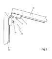
- FIG. 3 shows a side view of the in FIG. 2 shown section A.
- the connector element 10 connects the rails 21 and 22 at an angle ⁇ 90 °.
- the legs 11 and 12 of the connector element 10 are fastened with fastening means, for example with screws 31 on the rails 21 and 22.
- As an abutment for the screws 31 are preferably threaded plates (not visible here), which are fixed in a conventional manner within the rails 21, 22.
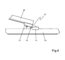
- FIG. 4 shows a side view of the in FIG. 2 shown section B.
- the rails 22 and 23 are interconnected by means of the connector element 10 according to the invention.
- the opening angle ⁇ for example, 15 ° between the rails 22 and 23
- the legs 11 and 12 of the connector element 10 are joined together in such a way that in comparison with that in the FIG. 1 shown arrangement of the legs 11 and 12 of the leg is rotated by 180 °. In this arrangement, not enclose the two legs 11 and 12, the opening angle ⁇ between the components to be fastened to each other 22 and 23.
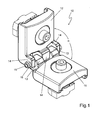
- FIG. 5 shows the connector element 10 according to the invention in the orientation of the legs 11 and 12 to each other, as in the designated B in section of the arrangement in FIG. 2 is used.
- the legs 11 and 12 are connected together so that the fastening means 31 is passed once from one side and once from the other side of the legs 11 and 12.
- a screw head of the fastening means 31 opposite side, a threaded plate 51 is provided in each case, which are provided for fixing the legs 11 and 12 to a rail or other component.
- Threaded plates 51 introduced in a conventional manner in a rail and fixed by engaging under inwardly projecting projections of the rail in a conventional manner.
- guide rails 52 and 53 are provided at the lateral outer edges of the legs 11 and 12 .
- the guide rails 52 and 53 are used for the simplified positioning of the connector element 10 on a profile rail, wherein the lateral guide rails 52, 53 are designed so that they embrace webs or sections of a rail from the outside (see FIG. 4 ) and thus facilitate the positioning and fixing of the connector element 10 on the rail and stabilize the connection.
- FIG. 6 shows a further embodiment 60 of the connector element according to the invention.
- the legs 61 and 62 are provided in the lateral areas with lateral guide rails 63 and 64.
- further strips 65 and 66 are provided parallel to the lateral guide rails 63 and 64 and extend substantially parallel to the lateral guide rails 63 and 64 in the region of the surface.
- the strips 65 and 66 are preferably designed so that they engage in corresponding sections of a rail and thus further facilitate the positioning and fixing of the connector element 60 on a rail and improve the grip.
- the mutually facing surfaces of the legs 61 and 62 are preferably convex, whereby on the one hand the stability of the connector element is further improved by an increased material thickness. On the other hand, the formation of sharp edges is avoided.
- both legs 61 and 62 are each provided with a round hole 67.
- one or both legs may instead have a slot to further increase variability in the use of the connector element 10.
- the round holes 67 or in the corresponding Because the slots may be surrounded by a recess 68 in the surface of the legs 61 and 62. This depression or recess 68 serves to flush receiving example countersunk screws.
- FIG. 7 shows a cross connector 70 according to the invention in a view obliquely from above.
- the cross connector 70 includes a first leg 71 and a second leg 72 that are substantially at right angles to each other.
- the second leg 72 has on its side facing away from the leg 71 a hook element 73 in the form of a parallel to the width of the leg 71 extending web.
- the hook element 73 is intended to fit into an insertion groove of a first profiled rail (see FIG FIG. 10 ) to be hooked. This may be, for example, a lateral insertion groove of a profile rail.
- the cross connector 70 can be connected by means of a fastening means to a further profiled rail (not shown here) or another component which can be arranged transversely to the first profiled rail.
- a fastening means to a further profiled rail (not shown here) or another component which can be arranged transversely to the first profiled rail.
- a conventional threaded plate can be used, which is fixed in a conventional manner within the other rail or below the other component.
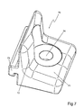
- FIG. 8 shows the cross connector 70 in a view obliquely from below.
- a thickening 81 in the form of a web is provided on the underside of the cross connector 70.
- the bottom of the cross connector 70 is not flat, but the cross connector 70 is located in the front area with the web 81 on the rail.
- the lateral areas of the cross connector 70 in the region of the leg 71 are provided with lateral guide rails 82. These guide rails 82 engage around portions of the rail when mounting the cross connector 70 on the rail, thereby further stabilizing the positioning and fastening of the cross connector 70 on the rail.
- FIG. 9 shows a sectional view of the cross connector 70 with the first leg 71 and the second leg 72.
- the first leg 71 has the central bore 74, which is provided for passing a fastening means.
- the first leg 71 facing away from the surface of the leg 72 is equipped with the web-shaped hook member 73.
- the underside of the front edge of the first leg 71 has a thickening 81 or a nose in the form of a parallel to the edge extending web.
- FIG. 10 illustrates the connection of two components 101 and 102 by means of the cross connector 70 according to the invention.
- the hook member 73 of the cross connector 70 engages in a lateral insertion groove 103 which forms a C-shaped receptacle, shown here in section a first rail 101 a.
- a fastening means in particular a screw 104
- the cross connector 70 is mounted on a further rail 102, which is shown here in side view.
- a threaded plate arranged within the profiled rail 102 serves as an abutment for the fastening means 104.
- the lateral guide strips 82 of the cross connector 70 surround the profiled rail 102 from the outside, so that the cross connector 70 is stably positioned on the profiled rail 102 is. Not visible in this illustration is the thickening 81 in the region of the front edge 105 of the cross connector 70, with which the cross connector 70 rests on the rail 102. As a result of the tensioning of the fastening means 104, the cross connector 70 hereby enters a hollow position and is pressed against the profile rail 101, so that the clamping effect of the hook element 73 within the lateral insertion groove 103 of the profile rail 101 is reinforced.
- a roof hook on a rail or a hanger bolt on a rail can be connected to each other by means of the cross connector 70 according to the invention, for example, a roof hook on a rail or a hanger bolt on a rail.
- FIG. 11 shows a further embodiment 110 of the cross connector according to the invention.
- a slot 114 is provided in this embodiment, which increases the variable usability of the cross connector 110.
- the mutually facing surfaces of the legs 111 and 112 of the cross connector 110 are substantially convex.
- a circumferential recess 115 is provided in order to provide a flat support surface for example, a screw head of a fastener.
- the convex curvature of the surface is interrupted by a recess or recess 116 to provide space for the operation of a fastener, if necessary.
Abstract
Description
Die vorliegende Erfindung betrifft ein Verbinderelement und einen Kreuzverbinder zur Verbindung von zwei Bauteilen.The present invention relates to a connector element and a cross connector for connecting two components.
Bei der Montage von Stützgerüsten, Unterkonstruktionen oder dergleichen, beispielsweise für Solaranlagen, sind verschiedene Bauteile miteinander zu verbinden. Grundbauelemente für derartige Konstruktionen sind Profilschienen, die mit anderen Bauteilen, wie beispielsweise Dachhaken, verschiedenartigen Klemmen und insbesondere auch mit weiteren Profilschienen, fest zu verbinden sind.When mounting scaffolding, substructures or the like, for example, for solar systems, various components are to be connected together. Basic components for such constructions are rails that are firmly connected to other components, such as roof hooks, various types of terminals and in particular with other rails.
Es sind hierfür bereits Verbinderelemente bekannt, die aus zwei in einem rechten Winkel zueinander stehenden Schenkeln bestehen, die jeweils eine Bohrung für ein Befestigungsmittel umfassen. Mit derartigen Verbinderelementen können beispielsweise zwei rechtwinklig zueinander stehende Profilschienen aneinander befestigt werden. Die Verbinderelemente können für die Befestigung einer Vielzahl unterschiedlicher Bauteile eingesetzt werden. Derartige Verbinderelemente haben jedoch den Nachteil, dass der Winkel, in dem die zu befestigenden Bauteile zueinander stehen, in der Regel auf 90° festgelegt ist. Dies ist beispielsweise dann nachteilig, wenn das Verbinderelement für eine Tragkonstruktion für eine Solaranlage eingesetzt werden soll, bei der bestimmte Winkel zur Ausrichtung von Solarmodulen im Hinblick auf die Sonneneinstrahlung zu realisieren sind. Bisher wurde dieses Problem beispielsweise dadurch gelöst, dass die Konstruktion bei Winkeln von größer oder kleiner 90° geschweißt wurde.There are already known connector elements for this purpose, which consist of two mutually perpendicular at a right angle legs, each comprising a bore for a fastener. With such connector elements, for example, two mutually perpendicular profile rails can be fastened together. The connector elements can be used for the attachment of a variety of different components. However, such connector elements have the disadvantage that the angle at which the components to be fastened to one another are generally fixed at 90 °. This is for example disadvantageous if the connector element for a support structure for a solar system is to be used, in which certain angles for the alignment of solar modules with respect to the sunlight are to be realized. So far, this problem has been solved, for example, that the construction at angles of greater or less 90 ° was welded.
Der Erfindung liegt die Aufgabe zugrunde, verbesserte Verbinderelemente bereitzustellen, die die geschilderten Nachteile von Verbinderelementen aus dem Stand der Technik beseitigen.The invention has for its object to provide improved connector elements, which eliminate the disadvantages of prior art connector elements.
Diese Aufgabe wird durch ein Verbinderelement und einen Kreuzverbinder gelöst, wie sie Gegenstand der unabhängigen Ansprüche sind. Durch die in den abhängigen Ansprüchen aufgeführten Maßnahmen sind vorteilhafte Weiterbildungen und Verbesserungen des in den unabhängigen Ansprüchen angegebenen Verbinderelementes und des Kreuzverbinders möglich.This object is achieved by a connector element and a cross connector, as they are the subject of the independent claims. The measures set forth in the dependent claims advantageous refinements and improvements of the connector element specified in the independent claims and the cross connector are possible.
Das erfindungsgemäße Verbinderelement ist zur Verbindung von zwei Bauteilen vorgesehen. Es umfasst zwei in einem Winkel zueinander stehende Schenkel und ist dadurch gekennzeichnet, dass beide Schenkel gelenkig miteinander verbunden sind. Der Kern der Erfindung liegt darin, dass durch die gelenkige Verbindung die beiden Schenkel des Verbinderelements zwei Bauteile in einem nahezu beliebigen Winkel miteinander verbunden werden können. Nach Einstellung des gewünschten Winkels kann dieser durch Feststellen der gelenkigen Verbindung fixiert werden. In anderen Ausführungsformen kann auf eine Feststellung des Winkels verzichtet werden, wenn sich der Winkel beispielsweise durch die Anordnung und die Länge der zu montierenden Bauteile, beispielsweise durch eine Rahmenkonstruktion aus Profilschienen, von selbst ergibt. Der besondere Vorteil liegt hierbei unter anderem darin, dass ein universell einsetzbares Verbinderelement für im Prinzip alle denkbaren Winkel eingesetzt werden kann. Es ist nicht erforderlich, für jeden gewünschten Winkel ein spezielles Verbinderelement mit einem festen, vorgegebenen Winkel zur Verfügung zu stellen und aufwendige Schweißverbindungen herzustellen. Der gewünschte Winkel kann während der Montage je nach Bedarf eingestellt und gegebenenfalls fixiert werden.The connector element according to the invention is intended for connection of two components. It comprises two legs which are at an angle to each other and is characterized in that both legs are hinged together. The essence of the invention lies in the fact that the two legs of the connector element two components can be connected to each other in an almost arbitrary angle by the articulated connection. After setting the desired angle this can be fixed by detecting the articulated connection. In other embodiments can be dispensed with a determination of the angle when the angle, for example, by the arrangement and the length of the components to be mounted, for example, by a frame construction of rails results by itself. The particular advantage here is, inter alia, that a universally applicable connector element for in principle all conceivable angle can be used. It is not necessary to provide a special connector element with a fixed, predetermined angle for each desired angle and to produce complex welded joints. The desired Angle can be adjusted during assembly as needed and fixed if necessary.
Die gelenkige Verbindung kann beispielsweise derart realisiert sein, dass beide Schenkel jeweils einen oder mehrere Vorsprünge aufweisen, die ineinandergesteckt werden können und jeweils mit Bohrungen versehen sind, die im zusammengesteckten Zustand fluchten und durch die ein Bolzen oder ein (Zylinder)stift gesteckt werden kann, um die gelenkige Verbindung zu realisieren. An den Enden des Zylinderstiftes können Gewinde für Schraubmuttern vorgesehen sein, um mit Hilfe der Schraubmuttern den Stift zu fixieren.The articulated connection can for example be realized such that both legs each have one or more projections that can be inserted into each other and are each provided with holes that are aligned in the assembled state and through which a pin or a (cylinder) pin can be inserted to realize the articulated connection. At the ends of the cylinder pin threads may be provided for screw nuts to fix with the help of the nuts the pin.
In einer bevorzugten Ausführungsform des erfindungsgemäßen Verbinderelements ist die gelenkige Verbindung lösbar. Dies kann beispielsweise durch die erwähnte Verbindung beider Schenkel durch einen Zylinderstift realisiert sein. Der Zylinderstift kann herausgezogen werden, um beide Schenkel voneinander zu trennen und in anderer Konstellation wieder miteinander zu verbinden. Der Vorteil dieser Ausführungsform liegt darin, dass die Schenkel in unterschiedlicher Ausrichtung zueinander je nach Anwendungsfall miteinander verbunden werden können. So können die Schenkel des Verbinderelements derart zusammengefügt werden, dass der Winkel zwischen zwei aneinander zu befestigenden Bauteilen sehr klein ist, wobei die Befestigung der Bauteile an dem Verbinderelement hierbei von einer Anordnung der Schenkel ausgeht, bei der die Schenkel gewissermaßen verdreht zueinander in einer Ebene liegen. Die Befestigung der Bauteile erfolgt bei einem Schenkel von oben und bei dem anderen Schenkel von unten. Hierdurch können sehr kleine Winkel der Bauteile zueinander realisiert werden. Die Lösbarkeit der gelenkigen Verbindung erhöht damit erheblich die Einsatzmöglichkeiten des erfindungsgemäßen Verbinderelementes.In a preferred embodiment of the connector element according to the invention, the articulated connection is releasable. This can be realized for example by the mentioned connection of both legs by a cylindrical pin. The cylinder pin can be pulled out to separate both legs from each other and connect again in a different constellation. The advantage of this embodiment is that the legs can be connected to each other in different orientation depending on the application. Thus, the legs of the connector element can be assembled such that the angle between two components to be fastened to each other is very small, wherein the attachment of the components to the connector element in this case starts from an arrangement of the legs, in which the legs are effectively twisted to each other in a plane , The attachment of the components takes place at one leg from above and at the other leg from below. As a result, very small angles of the components to each other can be realized. The solubility of the articulated connection thus considerably increases the possible uses of the connector element according to the invention.
Bei einer bevorzugten Ausführungsform ist vorgesehen, dass eine Fläche wenigstens eines Schenkels parallel zu den seitlichen Außenkanten seitliche Führungsleisten aufweist. Diese Führungsleisten können beispielsweise eine zu befestigende Profilschiene umgreifen, so dass hierdurch die Fixierung und die Befestigung des erfindungsgemäßen Verbinderelements an der Profilschiene erheblich erleichtert werden. Weiterhin wird hierdurch ein Verrutschen des Verbindungselements auf der Profilschiene oder einem anderen Bauteil vermieden und damit die Stabilität der Verbindung erhöht.In a preferred embodiment it is provided that a surface of at least one leg parallel to the lateral outer edges lateral Having guide rails. This guide rails can, for example, engage around a rail to be fastened, so that in this way the fixation and attachment of the connector element according to the invention are considerably facilitated on the rail. Furthermore, a slipping of the connecting element on the rail or another component is thereby avoided and thus increases the stability of the connection.
Mit Vorteil sind zwischen den seitlichen Führungsleisten ein oder mehrere parallel dazu verlaufende weitere Leisten vorgesehen. In anderen Ausführungsformen kann auf die seitlichen Führungsleisten verzichtet werden, sodass ausschließlich eine oder mehrere Leisten auf der Fläche des Schenkels vorgesehen sind. Diese Leisten sind vorzugsweise so angeordnet, dass sie an eine zu befestigende Profilschiene angepasst sind, indem sie beispielsweise in gegengleiche Vertiefungen oder Schlitze der Profilschiene eingreifen, wodurch die Positionierung und damit die Montage an der Profilschiene oder einem anderen Bauteil vereinfacht wird und weiterhin der Halt und die Stabilität der Verbindung verbessert wird.Advantageously, one or more parallel thereto extending further strips are provided between the lateral guide rails. In other embodiments may be dispensed with the lateral guide rails, so that only one or more strips are provided on the surface of the leg. These strips are preferably arranged so that they are adapted to be fastened to a rail by, for example, engage in the same recesses or slots of the rail, whereby the positioning and thus the mounting on the rail or other component is simplified, and further the support and the stability of the connection is improved.
Wenigstens eine der Flächen wenigstens eines Schenkels des erfindungsgemäßen Verbinderelements weist vorzugsweise eine konvexe Wölbung bzw. eine leichte Abrundung der Oberfläche auf. Hierdurch wird die Materialstärke des Verbinderelements erhöht und damit dessen Stabilität vergrößert. Weiterhin wird hierdurch die Ausbildung von scharfen Kanten vermieden, sodass die Handhabung für den Monteur angenehmer wird.At least one of the surfaces of at least one leg of the connector element according to the invention preferably has a convex curvature or a slight rounding of the surface. As a result, the material thickness of the connector element is increased and thus increases its stability. Furthermore, the formation of sharp edges is thereby avoided, so that the handling of the fitter is more pleasant.
Beide Schenkel des erfindungsgemäßen Verbinderelements können jeweils ein Rundloch oder jeweils ein Langloch aufweisen. Ein Langloch hat gegenüber einem Rundloch den Vorteil, dass die Befestigung des Verbinderelements variabler gestaltet werden kann, und die Verbindung zwischen dem Verbinderelement und dem Bauteil über das Langloch eingestellt werden kann. Es kann auch vorgesehen sein, dass einer der Schenkel ein Langloch und der andere Schenkel ein Rundloch aufweisen, sodass das Verbindungselement sehr variabel einsetzbar ist.Both legs of the connector element according to the invention may each have a round hole or one slot each. A slot has the advantage over a round hole that the attachment of the connector element can be made more variable, and the connection between the connector element and the component can be adjusted via the slot. It can also be provided that one of the Leg a slot and the other leg have a round hole, so that the connecting element is used very variable.
Das erfindungsgemäße Verbinderelement ist vorzugsweise aus einem Metall, beispielsweise aus Aluminium gefertigt. Vorzugsweise wird es aus Druckgussteilen hergestellt, beispielsweise aus Aluminiumdruckgussteilen oder Zinkdruckgussteilen. Es kann ferner auch aus Edelstahlteilen gefertigt sein.The connector element according to the invention is preferably made of a metal, for example made of aluminum. Preferably, it is made from die cast parts, for example, die-cast aluminum parts or zinc die-cast parts. It can also be made of stainless steel parts.
Das erfindungsgemäße Verbinderelement ist insbesondere dort mit Vorteil einsetzbar, wo zwei Bauteile in einem Winkel von ungleich 90° miteinander zu verbinden sind. Beispielsweise eignet es sich für die Montage von Trägergerüsten für Solaranlagen.The connector element according to the invention is particularly advantageous where two components are to be connected at an angle of not equal to 90 ° with each other. For example, it is suitable for the installation of support structures for solar systems.
Die Erfindung umfasst ferner ein Verbindungselement, das als Kreuzverbinder einsetzbar ist. Der Kreuzverbinder weist einen ersten und einen zweiten Schenkel auf, wobei die Schenkel in einem festen Winkel, insbesondere einem rechten Winkel, zueinander stehen. Der zweite Schenkel weist auf seiner dem ersten Schenkel abgewandten Fläche wenigstens ein Hakenelement, insbesondere einen parallel zu der Breite des Schenkels verlaufenden Steg auf. Dieses Hakenelement bzw. der Steg sind dazu vorgesehen, eine beispielsweise C-förmige Einlegenut einer ersten Profilschiene, insbesondere eine seitliche Einlegenut der Profilschiene, zu hintergreifen. Hierdurch kann der Kreuzverbinder verschiebbar in die Profilschiene eingehakt werden. Der andere bzw. der erste Schenkel des Kreuzverbinders ist mit einer Bohrung bzw. einer Aussparung versehen, durch die ein Befestigungsmittel hindurchgeführt werden kann, sodass an dem ersten Schenkel ein weiteres Bauteil, beispielsweise eine weitere Profilschiene, im rechten Winkel zu der ersten Profilschiene, in die der Kreuzverbinder eingehakt ist, befestigt werden kann. Erfindungsgemäß weist der erste Schenkel auf der von dem zweiten Schenkel abgewandten Fläche an dem offenen Ende des Schenkels im Bereich der Kante bzw. am äußeren Rand wenigstens eine Verdickung, insbesondere einen parallel zum Rand verlaufenden Steg auf. Durch diese Verdickung liegt der erste Schenkel nicht vollständig plan auf dem anderen Bauteil, beispielsweise der weiteren Profilschiene, auf. Vielmehr nimmt der erfindungsgemäße Kreuzverbinder durch diese Verdickung bei dem Spannen des Befestigungsmittels eine gewisse Hohllage ein und der Kreuzverbinder wird gegen die erste Profilschiene gedrückt, sodass sich die Einhakung des Hakenelements in der Einlegenut der ersten Profilschiene verspannt und hierdurch die Verbindung über das Hakenelement weiter stabilisiert und fixiert wird. Durch die Hohllage wird einem Kippmoment entgegengewirkt, sodass eine sehr feste Verbindung der beiden Bauteile über den erfindungsgemäßen Kreuzverbinder realisiert wird.The invention further comprises a connecting element, which can be used as a cross connector. The cross connector has a first and a second leg, wherein the legs are at a fixed angle, in particular a right angle to each other. The second leg has on its side facing away from the first leg at least one hook element, in particular a web extending parallel to the width of the leg. This hook element or the web are intended to engage behind an example C-shaped insertion of a first rail, in particular a lateral insertion of the rail. As a result, the cross connector can be slidably hooked into the rail. The other or the first leg of the cross connector is provided with a bore or a recess through which a fastener can be passed, so that on the first leg another component, such as a further rail, at right angles to the first rail, in the cross connector is hooked, can be attached. According to the invention, the first leg on the surface facing away from the second leg at the open end of the leg in the region of the edge or on the outer Edge at least one thickening, in particular a running parallel to the edge web on. Due to this thickening of the first leg is not completely flat on the other component, for example, the other rail on. Rather, the cross connector according to the invention takes by this thickening in the tensioning of the fastener a certain hollow position and the cross connector is pressed against the first rail, so that the hooking of the hook element in the insertion of the first rail clamped and thereby further stabilized the connection on the hook element and is fixed. Through the hollow layer a tilting moment is counteracted, so that a very firm connection of the two components is realized via the cross connector according to the invention.
Die Aussparung in dem ersten Schenkel für das Befestigungsmittel kann beispielsweise ein Langloch oder ein Rundloch sein. Ein Langloch hat den Vorteil einer größeren Flexibilität bei der Befestigung des erfindungsgemäßen Kreuzverbinders, indem die Verbindung zwischen dem Kreuzverbinder und dem weiteren Bauteil über das Langloch eingestellt werden kann.The recess in the first leg for the fastening means may be for example a slot or a round hole. A slot has the advantage of greater flexibility in the attachment of the cross connector according to the invention by the connection between the cross connector and the other component can be adjusted via the slot.
Vorzugsweise sind auf der von dem zweiten Schenkel abgewandten Fläche des ersten Schenkels parallel zu den Außenkanten seitlich verlaufende Führungsleisten vorgesehen. Diese Führungsleisten können beispielsweise eine darunter zu befestigende Profilschiene umgreifen und erleichtern so die Positionierung und die Fixierung des erfindungsgemäßen Kreuzverbinders. Weiterhin wird hierdurch die Verbindung des Kreuzverbinders mit der Profilschiene stabilisiert, da ein Verrutschen vermieden wir. Andere Ausführungsformen können ohne seitliche Führungsleisten realisiert sein, um den erfindungsgemäßen Kreuzverbinder noch variabler und unabhängig von der Gestaltung einer Profilschiene oder eines anderen Bauteils einsetzen zu können.Preferably, laterally extending guide rails are provided on the side facing away from the second leg surface of the first leg parallel to the outer edges. These guide strips can, for example, embrace a profile rail to be fastened underneath, and thus facilitate the positioning and fixing of the cross connector according to the invention. Furthermore, thereby the connection of the cross connector is stabilized with the rail as slipping we avoided. Other embodiments can be realized without lateral guide rails in order to use the cross connector according to the invention even more variable and independent of the design of a rail or other component.
Die einander zugewandten Flächen der Schenkel des erfindungsgemäßen Kreuzverbinders können jeweils eine konvexe Wölbung aufweisen. Hierdurch wird die Materialstärke des erfindungsgemäßen Kreuzverbinders und damit dessen Stabilität erhöht. Weiterhin werden durch die konvexe Wölbung scharfe Kanten vermieden, wodurch die Handhabung des erfindungsgemäßen Kreuzverbinders für den Monteur noch angenehmer wird.The mutually facing surfaces of the legs of the cross connector according to the invention may each have a convex curvature. As a result, the material thickness of the cross connector according to the invention and thus its stability is increased. Furthermore, sharp edges are avoided by the convex curvature, whereby the handling of the cross connector according to the invention for the fitter is even more pleasant.
In der Mitte der Fläche des zweiten Schenkels kann die gewölbte Fläche von einer zentralen Ausnehmung oder Vertiefung unterbrochen sein. Hierdurch kann der Zugang für die Betätigung des Befestigungsmittels erleichtert werden, insbesondere wenn der erfindungsgemäße Kreuzverbinder verhältnismäßig klein und die Bohrung im ersten Schenkel für das Befestigungsmittel relativ nah am zweiten Schenkel vorgesehen ist.In the middle of the surface of the second leg, the curved surface may be interrupted by a central recess or depression. In this way, the access for the actuation of the fastening means can be facilitated, in particular if the cross connector according to the invention is relatively small and the bore in the first leg for the fastening means is provided relatively close to the second leg.
Der erfindungsgemäße Kreuzverbinder ist vorzugsweise aus Metall gefertigt, um eine ausreichende Stabilität und Beständigkeit zu gewährleisten. Er kann beispielsweise als Strangpressprofil, insbesondere aus Aluminium, gefertigt sein. Besonders bevorzugt ist die Fertigung als Druckgussteil, beispielsweise als Aluminiumdruckgussteil oder Zinkdruckgussteil.The cross connector according to the invention is preferably made of metal in order to ensure sufficient stability and durability. It can be made, for example, as an extruded profile, in particular made of aluminum. Particularly preferred is the production as a die-cast part, for example as an aluminum die casting or zinc die-cast part.
Weitere Merkmale und Vorteile der Erfindung ergeben sich aus der nachfolgenden Beschreibung von Ausführungsbeispielen im Zusammenhang mit den Zeichnungen. Hierbei können die verschiedenen Merkmale jeweils für sich oder in Kombination miteinander verwirklicht sein.Further features and advantages of the invention will become apparent from the following description of embodiments in conjunction with the drawings. In this case, the various features can be implemented individually or in combination with each other.
In den Zeichnungen zeigen:
- Figur 1
- eine erste Ausführungsform eines erfindungsgemäßen Verbinderelements;
- Figur 2
- eine Anordnung von Profilschienen unter Verwendung von erfindungsgemäßen Verbinderelementen;
- Figur 3
- eine Seitenansicht des in
Figur 2 dargestellten Ausschnitts A; - Figur 4
- eine Seitenansicht des in
Figur 2 dargestellten Ausschnitts B; - Figur 5
- das in der
Figur 4 gezeigte Verbinderelement in detaillierter Darstellung; - Figur 6
- eine weitere Ausführungsform eines erfindungsgemäßen Verbinderelements;
- Figur 7
- eine erste Ausführungsform eines erfindungsgemäßen Kreuzverbinders in einer Ansicht von schräg oben;
- Figur 8
- der erfindungsgemäße Kreuzverbinder aus
Figur 7 in einer Ansicht von schräg unten; - Figur 9
- der Kreuzverbinder aus
Figur 7 in einer geschnittenen Darstellung; Figur 10- eine schematische Darstellung zweier mit einem erfindungsgemäßen Kreuzverbinder verbundener Profilschienen und
Figur 11- eine weitere Ausführungsform des erfindungsgemäßen Kreuzverbinders in einer Ansicht von schräg oben.
- FIG. 1
- a first embodiment of a connector element according to the invention;
- FIG. 2
- an arrangement of rails using connector elements according to the invention;
- FIG. 3
- a side view of the in
FIG. 2 section A shown; - FIG. 4
- a side view of the in
FIG. 2 shown section B; - FIG. 5
- that in the
FIG. 4 shown connector element in a detailed representation; - FIG. 6
- a further embodiment of a connector element according to the invention;
- FIG. 7
- a first embodiment of a cross connector according to the invention in a view obliquely from above;
- FIG. 8
- the cross connector according to the invention
FIG. 7 in a view obliquely from below; - FIG. 9
- the cross connector off
FIG. 7 in a sectional view; - FIG. 10
- a schematic representation of two associated with a cross connector according to the invention rails and
- FIG. 11
- a further embodiment of the cross connector according to the invention in a view obliquely from above.
Ausbildung der gelenkigen Verbindung sind die Vorsprünge 13, 14 mit Bohrungen versehen, sodass beim Zusammenführen der Teile 11 und 12 ein fluchtender Kanal gebildet wird, durch den ein Zylinderstift 15 geführt und damit die gelenkige Verbindung der Schenkel 11 und 12 hergestellt werden kann. Ein zwischen den Schenkeln 11 und 12 gebildeter Öffnungswinkel α des erfindungsgemäßen Verbinderelements 10 ist frei einstellbar, sodass das Verbinderelement 10 zur Verbindung von zwei Bauteilen, beispielsweise zwei Profilschienen, in einem beliebigen Winkel verwendet werden kann. Der beide Schenkel 11 und 12 miteinander verbindende Zylinderstift 15 kann beispielsweise mittels eines Schraubenkopfes und einer Mutter 16 feststellbar sein, sodass der Öffnungswinkel des Verbinderelements 10 festgelegt wird. In anderen Ausführungsformen kann der Öffnungswinkel variabel bleiben und sich durch die Anordnung der verschiedenen miteinander zu verbindenden Profilschienen oder anderen Bauteile ergeben.Formation of the articulated connection, the
Die
An den seitlichen Außenkanten der Schenkel 11 und 12 sind Führungsleisten 52 und 53 vorgesehen. Die Führungsleisten 52 und 53 dienen der vereinfachten Positionierung des Verbinderelements 10 auf einer Profilschiene, wobei die seitlichen Führungsleisten 52, 53 so gestaltet sind, dass sie Stege oder Abschnitte einer Profilschiene von außen umgreifen (siehe
Die einander zugewandten Flächen der Schenkel 61 und 62 sind vorzugsweise konvex gewölbt, wodurch zum einen die Stabilität des Verbinderelements durch eine erhöhte Materialstärke weiter verbessert wird. Zum anderen wird die Ausbildung von scharfen Kanten vermieden.The mutually facing surfaces of the
In dem hier gezeigten Ausführungsbeispiel sind beide Schenkel 61 und 62 jeweils mit einem Rundloch 67 versehen. In anderen Ausführungsformen kann einer oder können beide Schenkel stattdessen ein Langloch aufweisen, um die Variabilität bei der Verwendung des Verbinderelements 10 noch weiter zu erhöhen. Die Rundlöcher 67 oder in entsprechender Weise die Langlöcher können von einer Vertiefung bzw. Einsenkung 68 in der Oberfläche der Schenkel 61 und 62 umgeben sein. Diese Vertiefung oder Einsenkung 68 dient der bündigen Aufnahme von beispielsweise Senkkopfschrauben.In the embodiment shown here both
Die seitlichen Bereiche des Kreuzverbinders 70 im Bereich des Schenkels 71 sind mit seitlichen Führungsleisten 82 versehen. Diese Führungsleisten 82 umgreifen Abschnitte der Profilschiene bei der Befestigung des Kreuzverbinders 70 auf der Profilschiene, sodass hierdurch die Positionierung und Befestigung des Kreuzverbinders 70 auf der Profilschiene weiter stabilisiert wird.The lateral areas of the
Die schematische Darstellung in
Claims (7)
dadurch gekennzeichnet, dass eine der Flächen wenigstens eines Schenkels (11, 12; 61, 62) eine konvexe Wölbung aufweist.Connector element according to one of the preceding claims,
characterized in that one of the surfaces of at least one leg (11, 12; 61, 62) has a convex curvature.
dadurch gekennzeichnet, dass beide Schenkel (11, 12; 61, 62) jeweils ein Langloch oder jeweils ein Rundloch (67) aufweisen.Connector element according to one of the preceding claims,
characterized in that both legs (11, 12; 61, 62) each have a slot or a round hole (67).
Applications Claiming Priority (2)
| Application Number | Priority Date | Filing Date | Title |
|---|---|---|---|
| DE202009017491U DE202009017491U1 (en) | 2009-12-22 | 2009-12-22 | Connector element and cross connector |
| EP10014827A EP2341254B1 (en) | 2009-12-22 | 2010-11-22 | Connector element and cross connector |
Related Parent Applications (1)
| Application Number | Title | Priority Date | Filing Date |
|---|---|---|---|
| EP10014827.9 Division | 2010-11-22 |
Publications (1)
| Publication Number | Publication Date |
|---|---|
| EP2472130A1 true EP2472130A1 (en) | 2012-07-04 |
Family
ID=42105649
Family Applications (2)
| Application Number | Title | Priority Date | Filing Date |
|---|---|---|---|
| EP10014827A Not-in-force EP2341254B1 (en) | 2009-12-22 | 2010-11-22 | Connector element and cross connector |
| EP12001828A Withdrawn EP2472130A1 (en) | 2009-12-22 | 2010-11-22 | Connector element |
Family Applications Before (1)
| Application Number | Title | Priority Date | Filing Date |
|---|---|---|---|
| EP10014827A Not-in-force EP2341254B1 (en) | 2009-12-22 | 2010-11-22 | Connector element and cross connector |
Country Status (2)
| Country | Link |
|---|---|
| EP (2) | EP2341254B1 (en) |
| DE (1) | DE202009017491U1 (en) |
Families Citing this family (10)
| Publication number | Priority date | Publication date | Assignee | Title |
|---|---|---|---|---|
| DE102010042876A1 (en) * | 2010-10-25 | 2012-04-26 | Dauphin Entwicklungs- U. Beteiligungs-Gmbh | Connecting system for connecting pipes of frame structure for conference table, has pivot element variably linkable at pivot base so that contact surface of element and base surface of pivot base are variably arranged relative to each other |
| DE202010015841U1 (en) | 2010-11-26 | 2011-03-03 | Vm Edelstahltechnik Gmbh | connector element |
| DE102010052505B3 (en) * | 2010-11-26 | 2012-03-01 | Vm Edelstahltechnik Gmbh | Connector element and device for fixing solar modules |
| IT1404052B1 (en) * | 2011-02-08 | 2013-11-08 | Zamet Spa | MODULAR SYSTEM FOR THE CONSTRUCTION OF SUPPORT STRUCTURES FOR SOLAR PANELS. |
| DE102011017518A1 (en) * | 2011-04-26 | 2012-10-31 | Hilti Aktiengesellschaft | solar array |
| AT512283B1 (en) * | 2011-12-20 | 2013-07-15 | Mage Sunfixings Gmbh | SOLAR MOUNTING SYSTEM |
| FR3004524B1 (en) * | 2013-04-10 | 2015-04-24 | Thales Sa | CONTAINER OBJECT SUPPORT COMPRISING ISO CORNERS |
| DE102013008597A1 (en) * | 2013-05-22 | 2014-11-27 | Weinor Gmbh & Co. Kg | Mounting system for fastening guide rails |
| DE202014105882U1 (en) * | 2013-12-06 | 2014-12-17 | Ulrich Reif | Arrangement for connecting components, in particular two components of a substructure, in particular for balcony and terrace covers |
| CN105332579A (en) * | 2015-11-18 | 2016-02-17 | 清远市科建门窗幕墙装饰有限公司 | Hinge device capable of self-adapting to angle and position |
Citations (3)
| Publication number | Priority date | Publication date | Assignee | Title |
|---|---|---|---|---|
| FR2563293A1 (en) * | 1984-04-18 | 1985-10-25 | Technal France | Junction piece for assembling two profiled parts with clamping, notably bracket for assembling mitred parts and end pieces for end assembly |
| EP1439269A1 (en) * | 2003-01-14 | 2004-07-21 | Geberit Technik Ag | Bracket for mounting profiles for sanitary installations and frame with such a bracket |
| DE202004017022U1 (en) * | 2004-11-02 | 2006-03-16 | Rehau Ag + Co. | Bracket for connecting two mounting profiles has two arms, each of which is fixed to different profile, two lugs on each arm fitting into profile, but allowing bracket to slide along it, and locking nut being turned to lock it in place |
Family Cites Families (2)
| Publication number | Priority date | Publication date | Assignee | Title |
|---|---|---|---|---|
| US6722811B2 (en) * | 2002-02-20 | 2004-04-20 | Blanking Systems, Inc. | Lower frame assembly for blanking tool |
| IT1392116B1 (en) * | 2008-12-04 | 2012-02-09 | Alutecnica Srl | DETACHED REMOVABLE BRACKET FOR THE CONNECTION OF A STRUCTURAL ELEMENT TO A SUPPORT SURFACE |
-
2009
- 2009-12-22 DE DE202009017491U patent/DE202009017491U1/en not_active Expired - Lifetime
-
2010
- 2010-11-22 EP EP10014827A patent/EP2341254B1/en not_active Not-in-force
- 2010-11-22 EP EP12001828A patent/EP2472130A1/en not_active Withdrawn
Patent Citations (3)
| Publication number | Priority date | Publication date | Assignee | Title |
|---|---|---|---|---|
| FR2563293A1 (en) * | 1984-04-18 | 1985-10-25 | Technal France | Junction piece for assembling two profiled parts with clamping, notably bracket for assembling mitred parts and end pieces for end assembly |
| EP1439269A1 (en) * | 2003-01-14 | 2004-07-21 | Geberit Technik Ag | Bracket for mounting profiles for sanitary installations and frame with such a bracket |
| DE202004017022U1 (en) * | 2004-11-02 | 2006-03-16 | Rehau Ag + Co. | Bracket for connecting two mounting profiles has two arms, each of which is fixed to different profile, two lugs on each arm fitting into profile, but allowing bracket to slide along it, and locking nut being turned to lock it in place |
Also Published As
| Publication number | Publication date |
|---|---|
| EP2341254A3 (en) | 2011-12-14 |
| EP2341254B1 (en) | 2013-01-02 |
| DE202009017491U1 (en) | 2010-04-15 |
| EP2341254A2 (en) | 2011-07-06 |
Similar Documents
| Publication | Publication Date | Title |
|---|---|---|
| EP2472130A1 (en) | Connector element | |
| EP1956250B1 (en) | Rail-shaped profile | |
| EP2685111A1 (en) | Clamp piece for a detachable connection of two profile pieces | |
| DE202012012290U1 (en) | Fastening device for fastening plate-shaped components | |
| EP2527762A1 (en) | Attachment device | |
| DE102018221183B3 (en) | Adjustment fitting and support system for solar modules | |
| EP2440860B1 (en) | Adapter for support profiles | |
| WO2012175096A1 (en) | Connecting element | |
| EP2372269A2 (en) | Connecting device and profile assembly | |
| DE102011010828B4 (en) | Clamping device for releasably securing a device housing to a mounting rail | |
| DE202009012750U1 (en) | Dowel bolts of a connecting device | |
| DE202012104033U1 (en) | Holding device for a balustrade or railing plate and railing or parapet with disc | |
| EP2458302B1 (en) | Connector element and device for fixing solar modules | |
| EP2126378B1 (en) | Tensile/tilting connector system | |
| DE102007034432B4 (en) | Shuttering element for circular formwork | |
| DE102007009667B4 (en) | profile construction | |
| DE102012000827B4 (en) | Roof rails for a motor vehicle and method for attaching a roof rail cover | |
| DE3812179C2 (en) | ||
| DE102015222346A1 (en) | mounting clamp | |
| DE4329222C2 (en) | Fastening device for a device insert, especially in a worktop | |
| AT11492U1 (en) | DRIVE BAR WITH A CONNECTING ELEMENT | |
| DE102007051058A1 (en) | Fastening clamp for attachment of fabric coverings at framed walls of building, has supporting sections provided at opposite ends of bridge section that exhibits openings spaced at distance from each other for introduction of fastening unit | |
| EP1637749B1 (en) | Fastening device with a screw | |
| DE2354066C3 (en) | Clamping device for attaching fittings to undercut longitudinal grooves having metal or plastic hollow profiles for window and door frames or the like. | |
| DE102013013145B4 (en) | Connection system for profile strands |
Legal Events
| Date | Code | Title | Description |
|---|---|---|---|
| AC | Divisional application: reference to earlier application |
Ref document number: 2341254 Country of ref document: EP Kind code of ref document: P |
|
| AK | Designated contracting states |
Kind code of ref document: A1 Designated state(s): AL AT BE BG CH CY CZ DE DK EE ES FI FR GB GR HR HU IE IS IT LI LT LU LV MC MK MT NL NO PL PT RO RS SE SI SK SM TR |
|
| AX | Request for extension of the european patent |
Extension state: BA ME |
|
| PUAI | Public reference made under article 153(3) epc to a published international application that has entered the european phase |
Free format text: ORIGINAL CODE: 0009012 |
|
| 17P | Request for examination filed |
Effective date: 20121224 |
|
| RIC1 | Information provided on ipc code assigned before grant |
Ipc: F16B 7/18 20060101ALI20130620BHEP Ipc: F24J 2/52 20060101ALI20130620BHEP Ipc: F16B 7/04 20060101AFI20130620BHEP |
|
| GRAP | Despatch of communication of intention to grant a patent |
Free format text: ORIGINAL CODE: EPIDOSNIGR1 |
|
| INTG | Intention to grant announced |
Effective date: 20130920 |
|
| STAA | Information on the status of an ep patent application or granted ep patent |
Free format text: STATUS: THE APPLICATION IS DEEMED TO BE WITHDRAWN |
|
| 18D | Application deemed to be withdrawn |
Effective date: 20140131 |