EP2472004A1 - Papier - Google Patents
Papier Download PDFInfo
- Publication number
- EP2472004A1 EP2472004A1 EP11165898A EP11165898A EP2472004A1 EP 2472004 A1 EP2472004 A1 EP 2472004A1 EP 11165898 A EP11165898 A EP 11165898A EP 11165898 A EP11165898 A EP 11165898A EP 2472004 A1 EP2472004 A1 EP 2472004A1
- Authority
- EP
- European Patent Office
- Prior art keywords
- image
- paper
- pseudo
- magnetic material
- paper body
- Prior art date
- Legal status (The legal status is an assumption and is not a legal conclusion. Google has not performed a legal analysis and makes no representation as to the accuracy of the status listed.)
- Withdrawn
Links
Images

Classifications
-
- G—PHYSICS
- G06—COMPUTING OR CALCULATING; COUNTING
- G06K—GRAPHICAL DATA READING; PRESENTATION OF DATA; RECORD CARRIERS; HANDLING RECORD CARRIERS
- G06K19/00—Record carriers for use with machines and with at least a part designed to carry digital markings
- G06K19/06—Record carriers for use with machines and with at least a part designed to carry digital markings characterised by the kind of the digital marking, e.g. shape, nature, code
- G06K19/08—Record carriers for use with machines and with at least a part designed to carry digital markings characterised by the kind of the digital marking, e.g. shape, nature, code using markings of different kinds or more than one marking of the same kind in the same record carrier, e.g. one marking being sensed by optical and the other by magnetic means
- G06K19/10—Record carriers for use with machines and with at least a part designed to carry digital markings characterised by the kind of the digital marking, e.g. shape, nature, code using markings of different kinds or more than one marking of the same kind in the same record carrier, e.g. one marking being sensed by optical and the other by magnetic means at least one kind of marking being used for authentication, e.g. of credit or identity cards
-
- D—TEXTILES; PAPER
- D21—PAPER-MAKING; PRODUCTION OF CELLULOSE
- D21H—PULP COMPOSITIONS; PREPARATION THEREOF NOT COVERED BY SUBCLASSES D21C OR D21D; IMPREGNATING OR COATING OF PAPER; TREATMENT OF FINISHED PAPER NOT COVERED BY CLASS B31 OR SUBCLASS D21G; PAPER NOT OTHERWISE PROVIDED FOR
- D21H13/00—Pulp or paper, comprising synthetic cellulose or non-cellulose fibres or web-forming material
- D21H13/36—Inorganic fibres or flakes
- D21H13/38—Inorganic fibres or flakes siliceous
- D21H13/40—Inorganic fibres or flakes siliceous vitreous, e.g. mineral wool, glass fibres
-
- B—PERFORMING OPERATIONS; TRANSPORTING
- B42—BOOKBINDING; ALBUMS; FILES; SPECIAL PRINTED MATTER
- B42D—BOOKS; BOOK COVERS; LOOSE LEAVES; PRINTED MATTER CHARACTERISED BY IDENTIFICATION OR SECURITY FEATURES; PRINTED MATTER OF SPECIAL FORMAT OR STYLE NOT OTHERWISE PROVIDED FOR; DEVICES FOR USE THEREWITH AND NOT OTHERWISE PROVIDED FOR; MOVABLE-STRIP WRITING OR READING APPARATUS
- B42D25/00—Information-bearing cards or sheet-like structures characterised by identification or security features; Manufacture thereof
- B42D25/30—Identification or security features, e.g. for preventing forgery
- B42D25/36—Identification or security features, e.g. for preventing forgery comprising special materials
- B42D25/369—Magnetised or magnetisable materials
-
- G—PHYSICS
- G06—COMPUTING OR CALCULATING; COUNTING
- G06K—GRAPHICAL DATA READING; PRESENTATION OF DATA; RECORD CARRIERS; HANDLING RECORD CARRIERS
- G06K19/00—Record carriers for use with machines and with at least a part designed to carry digital markings
- G06K19/06—Record carriers for use with machines and with at least a part designed to carry digital markings characterised by the kind of the digital marking, e.g. shape, nature, code
-
- D—TEXTILES; PAPER
- D21—PAPER-MAKING; PRODUCTION OF CELLULOSE
- D21H—PULP COMPOSITIONS; PREPARATION THEREOF NOT COVERED BY SUBCLASSES D21C OR D21D; IMPREGNATING OR COATING OF PAPER; TREATMENT OF FINISHED PAPER NOT COVERED BY CLASS B31 OR SUBCLASS D21G; PAPER NOT OTHERWISE PROVIDED FOR
- D21H17/00—Non-fibrous material added to the pulp, characterised by its constitution; Paper-impregnating material characterised by its constitution
- D21H17/63—Inorganic compounds
-
- D—TEXTILES; PAPER
- D21—PAPER-MAKING; PRODUCTION OF CELLULOSE
- D21H—PULP COMPOSITIONS; PREPARATION THEREOF NOT COVERED BY SUBCLASSES D21C OR D21D; IMPREGNATING OR COATING OF PAPER; TREATMENT OF FINISHED PAPER NOT COVERED BY CLASS B31 OR SUBCLASS D21G; PAPER NOT OTHERWISE PROVIDED FOR
- D21H21/00—Non-fibrous material added to the pulp, characterised by its function, form or properties; Paper-impregnating or coating material, characterised by its function, form or properties
- D21H21/14—Non-fibrous material added to the pulp, characterised by its function, form or properties; Paper-impregnating or coating material, characterised by its function, form or properties characterised by function or properties in or on the paper
- D21H21/40—Agents facilitating proof of genuineness or preventing fraudulent alteration, e.g. for security paper
- D21H21/44—Latent security elements, i.e. detectable or becoming apparent only by use of special verification or tampering devices or methods
Definitions
- the present invention relates to a paper.
- a paper including:
- FIG. 1 is a plan view showing an example of the paper related to the exemplary embodiment.
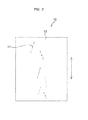
- FIG. 2 is a plan view showing the paper body used in the paper shown in FIG. 1 .
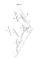
- FIG. 3 is a perspective view (partial, shown as a cross-sectional view) of part of the paper shown in FIG. 1 under magnification.
- the paper 100 related to the exemplary embodiment has a paper body 10 which contains pulp fiber 12 and a magnetic material 14 having a large Barkhausen effect, and an image 16 which is formed on at least one surface of the paper body 10 and is simulative of the magnetic material 14 contained in the paper body 10. That is, the paper 100 related to the exemplary embodiment has a pseudo-image 16 which is simulative of the magnetic material 14 that is in a state of being embedded in a papermaking manner, formed on the surface of the paper body 10 on which the magnetic material 14 having a large Barkhausen effect has been embedded in a papermaking manner.
- the magnetic material 14 having a large Barkhausen effect is embedded in a papermaking manner, and as shown in FIG. 3 , for example, the magnetic material 14 is present in the interior of the paper body 10.
- the magnetic material 14 is, for example, a fibrous magnetic fiber.
- six magnetic materials 14 are embedded in a papermaking manner in a linear shape per sheet of the paper body 10.
- the magnetic materials 14 embedded in a papermaking manner in the paper body 10 are aligned along the papermaking direction (direction of the arrow in FIG. 2 ), and the magnetic materials are localized in the central area with respect to the direction perpendicular to the papermaking direction, in the plane of the paper body 10.
- the magnetic materials 14 are present in a band-like area having a certain width, in the plane of the paper body 10.
- the band-like area is positioned in the central area of the direction perpendicular to a papermaking direction, in the plane of the paper body 10, and is extended in the papermaking direction.
- the position of the band-like area in which the magnetic materials 14 are present is not limited thereto.
- the magnetic materials 14 are embedded in a papermaking manner in a linear shape, but without being limited to this, the magnetic materials 14 may also be embedded in a papermaking manner in the paper body 10 in a curved state. Also, there are no particular limitations on the number of the magnetic materials 14 embedded in a papermaking manner per sheet of the paper body 10, and the direction and position of the magnetic materials 14 embedded in a papermaking manner in the paper body 10, and the number, direction and position are selected in accordance with the production method, size, applications, and the like of the paper body 10. Specifically, for example, the magnetic materials 14 are not localized in the central area of the paper body 10, and the magnetic materials 14 may be present over the entire area of the paper body.
- the pseudo-image 16 is an image which is simulative of the magnetic material 14 that is embedded in a papermaking manner in the paper body 10, as described above.
- the magnetic material 14 that is present in the interior of the paper body 10 is observed in such a manner that when the surface of the paper body 10 is observed from the outside of the paper body 10, the magnetic material 14 shows through the pulp fiber 12.
- the pulp fiber 12 is white in color
- the magnetic material 14 is a black magnetic fiber
- the magnetic material 14 is visible through the white pulp fiber 12. Therefore, the magnetic material 14 is seen as a linear form (fibrous form) having a color that is not darker (for example, gray) than the actual color (black).
- the image of that gray linear form is then used as the pseudo-image 16.
- the pseudo-image 16 is formed within the surface of the paper body 10, over the entire area where the magnetic material 14 is not formed.
- the position at which the pseudo-image 16 is formed is appropriately selected in accordance with the use or the like of the paper 100, and is not limited to the above-described form.
- the pseudo-image 16 may be formed over the entire surface of the paper 100, or the magnetic material 14 and the pseudo-image 16 may be formed to overlap each other.
- the pseudo-image 16 may also be formed in an area that is outside the area where it is desirable not to form the pseudo-image 16.
- the position and number of the pseudo-images 16 formed on the paper 100 are selected in accordance with the use or the like of the paper 100.
- a pseudo-image 16 is formed on both surfaces of the paper body 10, and the pseudo-images 16 formed on both the surfaces constitute an overlapping image when the images are projected in the thickness direction of the paper body 10.
- the term "thickness direction of the paper body 10" means a direction perpendicular to the paper surface of the paper body 10.
- the two images that overlap each other when the images are projected in the thickness direction of the paper body 10 may be referred to as a "projected overlapping image," and when at least part of the pseudo-image 16 formed on one surface of the paper body 10 (for example, the pseudo-image 16 shown in FIG.
- first image is overlapping with at least part of the pseudo-image 16 formed on the other surface of the paper body 10 (hereinafter, may be referred to as "second image”), the pseudo-image 16 referred to as the "projected overlapping image.”
- the first image and the second image constitute a matching image when the images are projected in the thickness direction of the paper body 10 (hereinafter, may be referred to as a "projected matching image").
- the first image and the second image are directed in the same direction, and the first image and the second image are at a position in which the two edges of the first image and the two edges of the second image coincide when the images are projected in the thickness direction of the paper body 10.
- an image which is simulative of the state in which the magnetic material 14 shows through when the paper 100 is visually inspected by reflected light that has been reflected from the surface of the paper 100 (for example, the paper 100 is placed on a table and observed) (hereinafter, may be referred to as a "reflected light pseudo-image"), as well as an image which is simulative of the state in which the magnetic material 14 shows through when the paper 100 is visually inspected by light transmitted through the paper 100 (for example, the paper 100 is observed by holding the paper up to the fluorescent light or sunlight) (hereinafter, may be referred to as a "transmitted light pseudo-image”) are both formed as a pseudo-image 16.
- the transmitted light pseudo-image constitutes an image of dark gray color, as compared with the reflected light pseudo-image.
- a paper body 10 is produced.
- An example of the method for producing the paper body 10 may be a method of obtaining a paper body 10 having a magnetic material 14 embedded in a papermaking manner, by adding a magnetic material dispersion liquid in which the magnetic material 14 is dispersed in a water-based medium, to a pulp slurry in which pulp fiber 12 is dispersed, and then papermaking the pulp fiber 12 including the magnetic material 14.
- those other materials that will be described below may be added, if necessary, to the magnetic material dispersion liquid, may be added to the pulp slurry, or may be added after the pulp fiber 12 including the magnetic material 14 has been papermade.
- a pseudo-image 16 is formed on the paper body 10 thus obtained.
- the pseudo-image 16 may be formed as a toner image by an electrophotographic system, the pseudo-image 16 may be formed as an ink image by an inkjet system, or the pseudo-image 16 may be formed by any other method.
- An example of the method of forming the pseudo-image 16 on the surface of the paper body 10 may be a method of forming a pseudo-image 16 by observing the surface of the paper body 10 in each case to obtain an image of the magnetic material 14 in the paper body 10, and printing the same image as the obtained image on the surface of the paper body 10, but is not limited to this.
- it is not necessarily needed to observe the surface of the paper body 10 on a case-by-case basis, and an image that has been previously obtained may be used to form the pseudo-image 16 on the surface of the paper body 10.
- an observation is carried out in accordance with the type of the pseudo-image 16 to be formed. That is, for example, in the case of using a reflected light pseudo-image as the pseudo-image 16, reflected light is used in a state in which the paper body 10 does not transmit light, and an observation of the surface of the pseudo-image 10 is carried out. Furthermore, for example, in the case of using a transmitted light pseudo-image as the pseudo-image 16, light is transmitted through the paper body 10, and an observation of the paper body 10 is carried out by the light transmitted through the paper.
- the paper 100 of the exemplary embodiment explained above has a pseudo-image 16 formed on the surface of the paper body 10 as described above, and therefore, the position of the magnetic material 14 contained in the paper body 10 is not easily identified visually.
- the magnetic material 14 may be observed through the pulp fiber 12 at the surface of the paper body 10. Accordingly, when there is no pseudo-image 16 formed on the surface, the positions of all of the magnetic materials 14 are easily identified only by visually observing the surface of the paper body 10.
- the paper 100 of the exemplary embodiment even if the surface is visually observed, it is difficult to distinguish between the pseudo-image formed on the paper body 10 and the magnetic material 14 that is embedded in a papermaking manner in the paper body 10. Therefore, it is thought that the position where the magnetic material 14 is actually present is not easily identified visually, as compared with the case in which there is no pseudo-image 16 formed.
- the position of the magnetic material 14 is not easily identified in the paper 100 according to the exemplary embodiment, for example, when the paper 100 is used as a recording medium for recording confidential information and the like that should not be brought up to the outside of a certain space, the leak of the confidential information and the like is suppressed as compared with the case in which other recording media are used.
- the magnetic material 14 passes through the boundary between the space and the surroundings, if there is provided a detecting means for detection purposes, when important documents having confidential information and the like recorded on the paper body 10 are taken out from the space to the outside, the taking out is detected since the paper body 10 contains the magnetic material 14.
- the paper 100 of the exemplary embodiment is used as a recording medium, since the position of the magnetic material 14 is not easily identified visually, there is no chance that, for example, cutting out of only the areas where the magnetic material 14 is not present from the paper 100 is easily achievable. Specifically, for example, in order to cut out for sure only the areas where the magnetic material 14 is not present, it is necessary to cut out only the areas in which there is no pseudo-image 16 formed, or to cut out the areas where the pseudo-image 16 is formed only after the pseudo-image 16 is distinguished from the magnetic material 14.
- a pseudo-image 16 is formed on the surface of the paper body 10 as described above, and therefore, the position of the magnetic material 14 is not easily identified. Accordingly, for example, there is no need for high costs, and it is easier to control the position or shape of the pseudo-image 16, as compared with the case in which a pseudo-material that is similar to the magnetic material 14 in terms of color, shape and size, is embedded in a papermaking manner together with the magnetic material 14. Furthermore, since there is an upper limit in the total amount of the magnetic material 14 and the pseudo-material that may be included in a papermaking manner in the paper body 10, the amount of the magnetic material 14 included in a papermaking manner is reduced as the amount of the pseudo-material used increases.
- the amount of the magnetic material 14 that is included in a papermaking manner is not reduced. Therefore, since the amount of the magnetic material 14 that is included in a papermaking manner is reduced as compared to the case of using a pseudo-material, it is contemplated that the position of the magnetic material 14 is not easily identified visually, while a decrease in the detection performance for the magnetic material 14 is suppressed.
- the pseudo-image 16 is formed on both sides of the paper body 10, even if the paper 100 is observed from any side, the magnetic material 14 that is embedded in a papermaking manner in the paper body 10 and the pseudo-image 16 are both visually recognized, and the position of the magnetic material 14 is not easily identified. Therefore, as compared with the case in which the pseudo-image 16 is formed only on one side of the paper body 10, it takes time to cut out only the areas in which the magnetic material 14 is not present, and it is thought that taking out of the paper will not be facilitated.
- the pseudo-image 16 is formed on both surfaces of the paper body 10, but without being limited to this, an embodiment having the pseudo-image 16 formed on only one surface of the paper body 10 may also be used.
- the pseudo-images 16 formed on the two surfaces constitute a projected overlapping image
- the pseudo-image 16 formed on both surfaces is not a projected overlapping image, much more efforts are needed to cut out only the areas in which the magnetic material 14 is not present, and it is thought that taking out of the paper will not be facilitated.
- the pseudo-image 16 formed on both surfaces is a projected coinciding image, it is difficult to distinguish the projected coinciding image from the state in which one piece of the magnetic material 14 that has been actually embedded in a papermaking manner shows through from both of the surfaces in the paper body 10.
- the pseudo-images 16 formed on the two surfaces constitute a projected coinciding image, but the pseudo-image 16 is not limited to this.
- the pseudo-image 16 may be a projected overlapping image in which parts of the pseudo-images 16 formed on the two surfaces overlap.
- the pseudo-image 16 may be in the form in which the first image and the second image intersect with each other, or the pseudo-image 16 may be in the form in which the first image and the second image are directed toward the same direction, with part thereof being overlapped.
- the pseudo-image 16 may be in the form in which when the paper is projected in the thickness direction of the paper body 10, the pseudo-images 16 formed on the two surfaces do not overlap, or may be in the form in which, for example, the pseudo-images 16 formed on the two surfaces are present nearby in the shapes that are in agreement with each other, and thereby it is difficult to distinguish the pseudo-images from one piece of the magnetic material 14.
- the paper 100 of the exemplary embodiment since both the reflected light pseudo-image and the transmitted light pseudo-image are formed, it is contemplated that it is more difficult to identify the position of the magnetic material even by visual inspection by light transmitted through the paper as well as by visual inspection by reflected light.
- the pseudo-image 16 is a reflected light pseudo-image only
- the magnetic material 14 in the paper body 10 appears darker than the reflected light pseudo-image as compared with the case in which the paper is visually inspected by reflected light, and therefore, it is thought that it is easier to distinguish between the magnetic material 14 and the pseudo-image 16.
- a reflected light pseudo-image and a transmitted light pseudo-image are both formed on the paper 100, since there are present pseudo-images 16 that are not easily distinguished from the magnetic material 14 even by visual inspection by light transmitted through the paper as well as by visual inspection by reflected light, it is thought that it is more difficult to identify the position of the magnetic material.
- a reflected light pseudo-image and a transmitted light pseudo-image are both formed in the exemplary embodiment, but the invention is not limited to this, and it is preferable that a pseudo-image 16 which conforms to any one or more methods among the methods for observing the surface of the paper 100 be formed on the paper body 10.
- all of the magnetic materials 14 are present in the interior of the paper body 10 (that is, central area in the thickness direction in the paper body 10), but the invention is not limited to this, and for example, an embodiment in which there are present magnetic materials 14 that are exposed at the surface of the paper body 10, is also acceptable.
- a pseudo-image 16 may be formed on the surface of the paper body 10, or an image other than the pseudo-image 16 may be formed in addition to the pseudo-image 16.
- the image other than the pseudo-image may be formed after only the pseudo-image is formed on the paper body, or an image obtained by integrating the pseudo-image and the image other than the pseudo-image may be formed on the paper body.
- the exemplary embodiment may be an embodiment in which a paper 100 having only a pseudo-image 16 formed on the surface of the paper body 10 is distributed, and the user forms an image other than the pseudo-image 16 on the paper 100, or an embodiment in which the user forms a pseudo-image 16 and an image other than the pseudo-image 16 on the paper body 10.
- the various constituent members material
- Symbols will not be indicated in the descriptions.
- the pulp fiber may be, for example, a chemical pulp, and specific examples thereof include wood pulps such as hardwood bleached kraft pulp, hardwood unbleached kraft pulp, softwood bleached kraft pulp, softwood unbleached kraft pulp, hardwood bleached sulfite pulp, hardwood unbleached sulfite pulp, softwood bleached sulfite pulp, and softwood unbleached sulfite pulp; and pulps produced by chemically treating fiber raw materials such as cotton, hemp and bast.
- wood pulps such as hardwood bleached kraft pulp, hardwood unbleached kraft pulp, softwood bleached kraft pulp, softwood unbleached kraft pulp, hardwood bleached sulfite pulp, hardwood unbleached sulfite pulp, softwood bleached sulfite pulp, and softwood unbleached sulfite pulp
- pulps produced by chemically treating fiber raw materials such as cotton, hemp and bast.
- a groundwood pulp produced by mechanically pulping wood or chips a chemimechanical pulp produced by soaking wood or chips with a chemical liquid and then mechanically pulping the wood or chips, a thermomechanical pulp produced by digesting chips until they become soft and then pulping the chips with a refiner, and the like may also be used as the pulp fiber.
- fibers such as cotton pulp fiber, hemp pulp fiber, kenaf pulp fiber, bagasse pulp fiber, viscose rayon fiber, recycled cellulose fibers, cuprammonium rayon fibers, cellulose acetate fibers, polyvinyl chloride-based fibers, polyacrylonitrile-based fibers, polyvinyl alcohol-based fibers, polyvinylidene chloride-based fibers, polyolefin-based fibers, polyurethane-based fibers, polyvinyl chloride, polyvinyl alcohol copolymers, fluorocarbon-based fibers, glass fibers, carbon fibers, alumina fibers, metal fibers, and silicon carbide fibers may also be used as the pulp fiber.
- fibers obtained by impregnating or thermally fusing pulp fiber with a synthetic resin such as polyethylene, polypropylene, polystyrene, polyvinyl chloride or polyester, may also be used.
- pulp fibers may be used in a virgin state only, or if necessary, high-quality and medium-quality recycled pulps may be incorporated.
- the amount of incorporation of the recycled pulp is determined in accordance with the use or purpose, but for example, in the case of incorporating recycled pulp, the recycled paper may be incorporated in an amount of 10% by weight or greater, or may be incorporated in an amount of 30% by weight or greater, based on the total amount of fiber.
- the pulp that is used in a virgin state may be a pulp which has been subjected to a bleaching treatment by a bleaching method of using chlorine dioxide without using chlorine gas (Elementally Chlorine Free; ECF), or a method of bleaching by mainly using ozone/hydrogen peroxide or the like without using a chlorine compound at all (Total Chlorine Free; TCF).
- ECF Exponal Chlorine Free
- TCF Total Chlorine Free
- unprinted recovered papers such as white shavings (Jouhaku), high-grade white wood-containing shavings (Tokuhaku), white wood-containing shavings (Chuuhaku), and white cuttings (Hakushon), which are shavings, cuttings and sheets produced by bookbinders, printing factories and sheet cutting facilities; printed recovered wood-free papers such as wood-free paper that has been subjected to printing or copying, and wood-free coated paper; recovered papers printed with aqueous ink, oil ink, pencil and the like; newspaper recovered papers including printed wood-free paper, coated wood-free paper, wood-containing paper, and wood-containing coated paper; recovered papers such as wood-containing paper, coated wood-containing paper, and groundwood paper, may also be incorporated.
- white shavings Jahaku
- Tokuhaku high-grade white wood-containing shavings
- Chouhaku white wood-containing shavings
- Haakushon white cuttings
- the recycled pulp may be a product obtained by treating recovered paper raw materials with at least one of an ozone bleaching treatment and a hydrogen peroxide bleaching treatment. Furthermore, the mixing ratio of the recycled pulp obtained by those bleaching treatments may be from 50% by weight to 100% by weight.
- the magnetic material is not particularly limited in terms of the magnetic properties, composition, shape and the like, as long as the magnetic material is a magnetic material having characteristics that cause a large Barkhausen effect, and an example of the magnetic material may be a magnetic fiber, which is a fibrous magnetic material (in other words, linear or band-shaped).
- composition of the magnetic fiber examples include alloys (for example, Co-based, Fe-based and Ni-based alloys, mixtures thereof; specifically, for example, Co-B-Si, and Co-Fe-B-Si) containing magnetic elements (for example, Co, Fe and Ni), transition metals and glass-forming elements (for example, Si, B, C and P), and when the composition ratio of the constituent elements or the production method is appropriately selected, magnetic fibers having various magnetic characteristics may be used.
- the hue of amorphous alloys formed from the elements described above is not much affected by the proportions of the elements.
- the shape and size of the magnetic fiber for example, if the thickness of the paper body is from 80 ⁇ m to 120 ⁇ m, a magnetic fiber having a circular cross-section and an outer diameter (fiber diameter) of from 10 ⁇ m to 60 ⁇ m.
- the external shape of the magnetic fiber may be from 15 ⁇ m to 55 ⁇ m, and may also be from 25 ⁇ m to 45 ⁇ m.
- the length of the magnetic fiber for example, in the case of a fiber having an outer diameter of from 10 ⁇ m to 60 ⁇ m, the length may be from 5 mm to 40 mm.
- the magnetic fiber may be used as received, but for example, may also be used as a fiber-shaped composite material coated with a material such as a resin or glass (that is, having a coating layer composed of a material such as a resin or glass).
- a resin or glass that is, having a coating layer composed of a material such as a resin or glass.
- the resin include polyimides.
- the thickness of the coating layer may be, for example, from 2.5 ⁇ m to 10 ⁇ m, and may also be from 2.0 ⁇ m to 5.0 ⁇ m.
- the method for forming the coating layer may be selected in accordance with the material of the coating layer, and examples include gas phase film-forming methods such as a sputtering method, a chemical vapor deposition (CVD) method, and a vacuum deposition method; and liquid phase film-forming methods such as coating using an immersion coating method, a roller coating method, a spray coating method and a sol-gel method.
- gas phase film-forming methods such as a sputtering method, a chemical vapor deposition (CVD) method, and a vacuum deposition method
- liquid phase film-forming methods such as coating using an immersion coating method, a roller coating method, a spray coating method and a sol-gel method.
- the Curie temperature of the magnetic material may be, for example, in the case of fixing the image on the paper body by heat fixing, 200°C or higher, or may also be 300°C or higher.
- the term "Curie temperature” is also referred to as Curie point, and is a temperature at which when an amorphous material reaches this particular temperature, even after cooling, a change in the physical structure occurs in the amorphous state, so that the material loses its characteristics (for example, a large Barkhausen effect).
- the magnetic fiber may be obtained by, for example, melting a magnetic material, passing the molten material through a discharge outlet having a shape that is corresponding to the cross-sectional shape of the magnetic fiber, and then cooling the fiber.
- a discharge outlet having a shape that is corresponding to the cross-sectional shape of the magnetic fiber
- cooling the fiber Specifically, for example, an in-water rotary spinning method or the like is used.
- a coating layer may be formed by a gas phase film-forming method such as CVD, for the purpose of cooling of the magnetic fiber as well.
- a magnetic fiber coated with a coating layer of glass or the like may also be produced according to the production method described in USP 3,256,584 (Taylor-Ulitovsky method). Specifically, for example, a metal alloy is charged into a glass tube, the front tip of the glass tube is melted by overheating with an induction coil to produce a state in which a molten metal material is coated around with molten glass, and the resultant is rapidly cooled with a coolant. Thereby, a magnetic fiber in which an amorphous magnetic wire is coated with glass, is obtained.
- the paper body may include, if necessary, other materials in addition to the pulp fiber and the magnetic material.
- specific examples of the other materials include loading materials for regulating the opacity, white color and surface properties of the paper body.
- the loading material examples include white inorganic pigments such as heavy calcium carbonate, light calcium carbonate, chalk, kaolin, calcined clay, talc, calcium sulfate, barium sulfate, titanium dioxide, zinc oxide, zinc sulfide, zinc carbonate, aluminum silicate, calcium silicate, magnesium silicate, synthetic silica, aluminum hydroxide, alumina, sericite, white carbon, saponite, calcium montmorillonite, sodium montmorillonite, and bentonite; and organic pigments such as acrylic plastic pigments, polyethylene, and urea resins.
- thermoplastic resin particles for example, polyester-based or styrene-acrylic-based resin particles
- the fraction of the loading material contained in the recovered raw material may be estimated in advance, and the amount of addition of the loading material may be adjusted.
- the amount of incorporation of the inorganic pigment may be, for example, from 0% by weight to 10% by weight, and may also be from 0% by weight to 8% by weight.
- the amount of incorporation of the organic pigment may be, for example, from 0% by weight to 10% by weight, and may also be from 0% by weight to 5% by weight.
- various chemicals such as a sizing agent may also be used in addition to the loading material.
- the various chemicals such as a sizing agent are added to the paper body by, for example, internal addition or external addition.
- the type of the sizing agent include sizing agents such as a rosin-based sizing agent, a synthetic sizing agent, a petroleum resin-based sizing agent and a neutral sizing agent, and the sizing agent may also be used in combination with a fiber fixing agent such as sulfuric acid band or a cationized starch.
- Examples of the neutral sizing agent include an alkenyl succinic anhydride-based sizing agent, an alkyl ketene dimer, an alkenyl ketene dimer, neutral rosin, a petroleum size, an olefin-based resin, and a styrene-acrylic resin.
- examples of the surface sizing agent include oxidized modified starch, enzyme modified starch, polyvinyl alcohol, and cellulose modification products such as carboxymethyl cellulose, and these may be used singly or in combination.
- a cationic material which adjusts the surface of the paper body to be cationic may also be used.
- the surface of the paper body may be treated with a hydrophilic cationic resin or the like.
- an inorganic material which regulates the electrical resistivity of the paper such as sodium chloride, potassium chloride, calcium chloride, sodium sulfate, zinc oxide, titanium dioxide, tin oxide, aluminum oxide or magnesium oxide; or an organic material which regulates the electrical resistivity, such as an alkyl phosphoric acid ester acid, an alkyl sulfuric acid ester acid, sulfonic acid sodium salt, a quaternary ammonium salt, may be used singly or in mixture.
- a paper strengthening agent may also be used, and specifically, a paper strengthening agent may be added by internal addition or external addition.
- the paper strengthening agent include starch, modified starch, plant gums, carboxymethyl cellulose, polyvinyl alcohol, modified polyvinyl alcohol, polyacrylamide, a styrene-maleic anhydride copolymer, a vinyl chloride-vinyl acetate copolymer, a styrene-butadiene copolymer, a polyacrylic acid ester urea-formaldehyde resin, a melamine-formaldehyde resin, dialdehyde starch, polyethyleneimine, epoxidated polyamide, a polyamide-epichlorohydrin-based resin, methylolated polyamide, and chitosan derivatives, and these materials may be used singly or in mixture.
- auxiliary agents that are incorporated into the paper base for conventional coated paper, such as a dye and a pH adjusting agent, may also be used as necessary.
- the basis weight (JIS P-8124) of the paper body is not particularly defined, but may be, for example, in the range of from 50 g/m 2 to 105 g/m 2 . Furthermore, the thickness of the paper body may be, for example, in the range of from 80 ⁇ m to 120 ⁇ m.
Landscapes
- Chemical & Material Sciences (AREA)
- Inorganic Chemistry (AREA)
- Physics & Mathematics (AREA)
- General Physics & Mathematics (AREA)
- Engineering & Computer Science (AREA)
- Theoretical Computer Science (AREA)
- Paper (AREA)
- Credit Cards Or The Like (AREA)
Applications Claiming Priority (1)
| Application Number | Priority Date | Filing Date | Title |
|---|---|---|---|
| JP2010269373A JP5640702B2 (ja) | 2010-12-02 | 2010-12-02 | 用紙 |
Publications (1)
| Publication Number | Publication Date |
|---|---|
| EP2472004A1 true EP2472004A1 (de) | 2012-07-04 |
Family
ID=44185732
Family Applications (1)
| Application Number | Title | Priority Date | Filing Date |
|---|---|---|---|
| EP11165898A Withdrawn EP2472004A1 (de) | 2010-12-02 | 2011-05-12 | Papier |
Country Status (5)
| Country | Link |
|---|---|
| US (1) | US8584960B2 (de) |
| EP (1) | EP2472004A1 (de) |
| JP (1) | JP5640702B2 (de) |
| KR (1) | KR101462069B1 (de) |
| CN (1) | CN102486013B (de) |
Families Citing this family (5)
| Publication number | Priority date | Publication date | Assignee | Title |
|---|---|---|---|---|
| BR102013003501A2 (pt) * | 2013-02-15 | 2015-01-06 | Nathan Tafla Rabinovitch | Processo para obtenção de folha celulósica magnética e o respectivo produto |
| JP6361209B2 (ja) * | 2014-03-25 | 2018-07-25 | セイコーエプソン株式会社 | シート製造装置、シート製造方法及びシート |
| CN106192574A (zh) * | 2015-04-03 | 2016-12-07 | 北京恒维科技有限公司 | 一种防盗安全纸 |
| JP7219004B2 (ja) | 2015-04-20 | 2023-02-07 | タギト-イーエーエス リミティッド | 記録媒体 |
| WO2019008576A1 (en) * | 2017-07-05 | 2019-01-10 | Tagit S.A. | METHOD FOR PRODUCING SECURITY PAPER |
Citations (11)
| Publication number | Priority date | Publication date | Assignee | Title |
|---|---|---|---|---|
| US3256584A (en) | 1963-02-12 | 1966-06-21 | Inst Metallurg A A Baikov | Installation for production of glass insulated microwire directly from liquid metal |
| WO1997024734A1 (en) * | 1995-12-27 | 1997-07-10 | Institutul De Fizica Tehnica | Amorphous and nanocrystalline glass-covered wires and process for their production |
| US20060209147A1 (en) * | 2005-03-17 | 2006-09-21 | Fuji Xerox Co., Ltd. | Magnetic wire application apparatus, method thereof and printed material including magnetic wire |
| US20060232829A1 (en) * | 2005-03-16 | 2006-10-19 | Fuji Xerox Co., Ltd. | Information holding method |
| US20070040037A1 (en) * | 2005-08-16 | 2007-02-22 | Fuji Xerox Co., Ltd. | Scanned medium, and manufacturing apparatus and method therefor |
| US20070145967A1 (en) * | 2005-12-26 | 2007-06-28 | Fuji Xerox Co., Ltd. | Recording medium detecting system |
| US20070243403A1 (en) * | 2006-04-14 | 2007-10-18 | Fuji Xerox Co., Ltd. | Recording paper |
| US20080013212A1 (en) * | 2006-07-12 | 2008-01-17 | Fuji Xerox Co., Ltd. | Magnetic wire and recording medium |
| US20080018674A1 (en) * | 2006-07-21 | 2008-01-24 | Fuji Xerox Co., Ltd. | Recording medium and sheet |
| US20080226849A1 (en) * | 2007-03-12 | 2008-09-18 | Tsukasa Matsuda | Recording Paper |
| US20090017334A1 (en) * | 2007-07-10 | 2009-01-15 | Fuji Xerox Co., Ltd. | Recording paper |
Family Cites Families (10)
| Publication number | Priority date | Publication date | Assignee | Title |
|---|---|---|---|---|
| JP2587944B2 (ja) * | 1987-07-31 | 1997-03-05 | 新富士製紙株式会社 | 模様紙の製造法 |
| US5601931A (en) * | 1993-12-02 | 1997-02-11 | Nhk Spring Company, Ltd. | Object to be checked for authenticity and a method for manufacturing the same |
| US5944927A (en) * | 1997-05-29 | 1999-08-31 | The Standard Register Company | Security paper having an embedded security thread and a process for making the security paper |
| DE19829004A1 (de) * | 1998-06-30 | 2000-01-05 | Giesecke & Devrient Gmbh | Sicherheitspapier |
| JP2004110689A (ja) * | 2002-09-20 | 2004-04-08 | Fuji Xerox Co Ltd | 印刷媒体への付加情報記録装置及びその方法、画像形成装置 |
| US20070099130A1 (en) * | 2003-06-25 | 2007-05-03 | Hideaki Takahashi | Developer for recording materials |
| JP4483647B2 (ja) | 2005-03-24 | 2010-06-16 | 富士ゼロックス株式会社 | 磁性素子を付与した媒体、媒体の情報読取方法および装置 |
| JP4792850B2 (ja) * | 2005-07-15 | 2011-10-12 | 富士ゼロックス株式会社 | 記録媒体 |
| US20070178260A1 (en) * | 2006-01-27 | 2007-08-02 | Avery Levy | Paper having discrete regions of ferromagnetic material and process of making the same |
| FR2922227B1 (fr) * | 2007-10-12 | 2009-12-18 | Arjowiggins Licensing Sas | Feuille comprenant au moins un filigrane observable que d'une face de la feuille |
-
2010
- 2010-12-02 JP JP2010269373A patent/JP5640702B2/ja not_active Expired - Fee Related
-
2011
- 2011-04-18 US US13/088,469 patent/US8584960B2/en not_active Expired - Fee Related
- 2011-05-09 KR KR1020110043325A patent/KR101462069B1/ko active Active
- 2011-05-10 CN CN201110119639.8A patent/CN102486013B/zh active Active
- 2011-05-12 EP EP11165898A patent/EP2472004A1/de not_active Withdrawn
Patent Citations (11)
| Publication number | Priority date | Publication date | Assignee | Title |
|---|---|---|---|---|
| US3256584A (en) | 1963-02-12 | 1966-06-21 | Inst Metallurg A A Baikov | Installation for production of glass insulated microwire directly from liquid metal |
| WO1997024734A1 (en) * | 1995-12-27 | 1997-07-10 | Institutul De Fizica Tehnica | Amorphous and nanocrystalline glass-covered wires and process for their production |
| US20060232829A1 (en) * | 2005-03-16 | 2006-10-19 | Fuji Xerox Co., Ltd. | Information holding method |
| US20060209147A1 (en) * | 2005-03-17 | 2006-09-21 | Fuji Xerox Co., Ltd. | Magnetic wire application apparatus, method thereof and printed material including magnetic wire |
| US20070040037A1 (en) * | 2005-08-16 | 2007-02-22 | Fuji Xerox Co., Ltd. | Scanned medium, and manufacturing apparatus and method therefor |
| US20070145967A1 (en) * | 2005-12-26 | 2007-06-28 | Fuji Xerox Co., Ltd. | Recording medium detecting system |
| US20070243403A1 (en) * | 2006-04-14 | 2007-10-18 | Fuji Xerox Co., Ltd. | Recording paper |
| US20080013212A1 (en) * | 2006-07-12 | 2008-01-17 | Fuji Xerox Co., Ltd. | Magnetic wire and recording medium |
| US20080018674A1 (en) * | 2006-07-21 | 2008-01-24 | Fuji Xerox Co., Ltd. | Recording medium and sheet |
| US20080226849A1 (en) * | 2007-03-12 | 2008-09-18 | Tsukasa Matsuda | Recording Paper |
| US20090017334A1 (en) * | 2007-07-10 | 2009-01-15 | Fuji Xerox Co., Ltd. | Recording paper |
Also Published As
| Publication number | Publication date |
|---|---|
| JP5640702B2 (ja) | 2014-12-17 |
| KR101462069B1 (ko) | 2014-11-18 |
| KR20120060725A (ko) | 2012-06-12 |
| US20120138692A1 (en) | 2012-06-07 |
| JP2012118865A (ja) | 2012-06-21 |
| US8584960B2 (en) | 2013-11-19 |
| CN102486013A (zh) | 2012-06-06 |
| CN102486013B (zh) | 2015-07-15 |
Similar Documents
| Publication | Publication Date | Title |
|---|---|---|
| US8584960B2 (en) | Paper | |
| JP4433008B2 (ja) | 記録用紙 | |
| JP5365169B2 (ja) | 印刷用顔料塗被紙 | |
| JP5577875B2 (ja) | 印刷用顔料塗被紙及びその製造方法 | |
| CN101290483A (zh) | 磁线和记录介质 | |
| CN102758379B (zh) | 片材 | |
| JP4847191B2 (ja) | 記録用紙 | |
| JP5577876B2 (ja) | 印刷用顔料塗被紙およびその製造方法 | |
| JP5577877B2 (ja) | 印刷用顔料塗被紙及び印刷用顔料塗被紙の製造方法 | |
| JP5577878B2 (ja) | 印刷用顔料塗被紙、印刷用顔料塗被紙の製造方法 | |
| JP4956993B2 (ja) | 記録媒体検知システム | |
| US7638209B2 (en) | Recording medium | |
| JP4983019B2 (ja) | 紙の製造方法、紙の製造装置 | |
| JP4807065B2 (ja) | 記録媒体、及びその製造方法 | |
| WO2018155649A1 (ja) | コールドセット型オフセット印刷用塗工紙 | |
| JP2007177361A (ja) | 磁性ワイア、及び該磁性ワイアを含む印刷用紙 | |
| JP4828289B2 (ja) | 記録用紙 | |
| JP2006183192A (ja) | 印刷用紙 |
Legal Events
| Date | Code | Title | Description |
|---|---|---|---|
| AK | Designated contracting states |
Kind code of ref document: A1 Designated state(s): AL AT BE BG CH CY CZ DE DK EE ES FI FR GB GR HR HU IE IS IT LI LT LU LV MC MK MT NL NO PL PT RO RS SE SI SK SM TR |
|
| AX | Request for extension of the european patent |
Extension state: BA ME |
|
| PUAI | Public reference made under article 153(3) epc to a published international application that has entered the european phase |
Free format text: ORIGINAL CODE: 0009012 |
|
| 17P | Request for examination filed |
Effective date: 20130102 |
|
| STAA | Information on the status of an ep patent application or granted ep patent |
Free format text: STATUS: THE APPLICATION HAS BEEN WITHDRAWN |
|
| 18W | Application withdrawn |
Effective date: 20140117 |