EP2471714B1 - Générateur solaire plan deroulable - Google Patents
Générateur solaire plan deroulable Download PDFInfo
- Publication number
- EP2471714B1 EP2471714B1 EP11192099.7A EP11192099A EP2471714B1 EP 2471714 B1 EP2471714 B1 EP 2471714B1 EP 11192099 A EP11192099 A EP 11192099A EP 2471714 B1 EP2471714 B1 EP 2471714B1
- Authority
- EP
- European Patent Office
- Prior art keywords
- tape
- membrane
- deployment
- flexible
- spring
- Prior art date
- Legal status (The legal status is an assumption and is not a legal conclusion. Google has not performed a legal analysis and makes no representation as to the accuracy of the status listed.)
- Not-in-force
Links
- 239000012528 membrane Substances 0.000 claims description 35
- 239000002131 composite material Substances 0.000 claims description 12
- 239000000463 material Substances 0.000 claims description 7
- 229920001169 thermoplastic Polymers 0.000 claims description 3
- 239000004416 thermosoftening plastic Substances 0.000 claims description 3
- 230000001131 transforming effect Effects 0.000 claims description 3
- 239000002184 metal Substances 0.000 claims description 2
- 229910001218 Gallium arsenide Inorganic materials 0.000 claims 1
- 230000001747 exhibiting effect Effects 0.000 claims 1
- 239000012815 thermoplastic material Substances 0.000 description 4
- 238000004804 winding Methods 0.000 description 4
- 238000010586 diagram Methods 0.000 description 2
- 238000010438 heat treatment Methods 0.000 description 2
- 239000007769 metal material Substances 0.000 description 2
- JBRZTFJDHDCESZ-UHFFFAOYSA-N AsGa Chemical compound [As]#[Ga] JBRZTFJDHDCESZ-UHFFFAOYSA-N 0.000 description 1
- 229910017214 AsGa Inorganic materials 0.000 description 1
- 240000008042 Zea mays Species 0.000 description 1
- 238000005452 bending Methods 0.000 description 1
- 239000004918 carbon fiber reinforced polymer Substances 0.000 description 1
- 238000010276 construction Methods 0.000 description 1
- 230000002427 irreversible effect Effects 0.000 description 1
- 238000006116 polymerization reaction Methods 0.000 description 1
- 230000000750 progressive effect Effects 0.000 description 1
- 229920001187 thermosetting polymer Polymers 0.000 description 1
Images

Classifications
-
- B—PERFORMING OPERATIONS; TRANSPORTING
- B64—AIRCRAFT; AVIATION; COSMONAUTICS
- B64G—COSMONAUTICS; VEHICLES OR EQUIPMENT THEREFOR
- B64G1/00—Cosmonautic vehicles
- B64G1/22—Parts of, or equipment specially adapted for fitting in or to, cosmonautic vehicles
- B64G1/42—Arrangements or adaptations of power supply systems
- B64G1/44—Arrangements or adaptations of power supply systems using radiation, e.g. deployable solar arrays
-
- B—PERFORMING OPERATIONS; TRANSPORTING
- B64—AIRCRAFT; AVIATION; COSMONAUTICS
- B64G—COSMONAUTICS; VEHICLES OR EQUIPMENT THEREFOR
- B64G1/00—Cosmonautic vehicles
- B64G1/22—Parts of, or equipment specially adapted for fitting in or to, cosmonautic vehicles
- B64G1/222—Parts of, or equipment specially adapted for fitting in or to, cosmonautic vehicles for deploying structures between a stowed and deployed state
-
- Y—GENERAL TAGGING OF NEW TECHNOLOGICAL DEVELOPMENTS; GENERAL TAGGING OF CROSS-SECTIONAL TECHNOLOGIES SPANNING OVER SEVERAL SECTIONS OF THE IPC; TECHNICAL SUBJECTS COVERED BY FORMER USPC CROSS-REFERENCE ART COLLECTIONS [XRACs] AND DIGESTS
- Y02—TECHNOLOGIES OR APPLICATIONS FOR MITIGATION OR ADAPTATION AGAINST CLIMATE CHANGE
- Y02E—REDUCTION OF GREENHOUSE GAS [GHG] EMISSIONS, RELATED TO ENERGY GENERATION, TRANSMISSION OR DISTRIBUTION
- Y02E10/00—Energy generation through renewable energy sources
- Y02E10/50—Photovoltaic [PV] energy
- Y02E10/544—Solar cells from Group III-V materials
Definitions
- the field of the invention is that of deployable structures in space that can advantageously be used for the deployment of solar generators.
- Tape-ribbons - tape-spring in English - are known as such in the spatial field as being ribbons capable of passing from the wound state to the unwound state essentially by virtue of their own elastic energy; in the unrolled state, known meter-ribbons generally have a rigidity able to maintain them in this state, cf. US 2007/0262204 .
- the Applicant has already demonstrated that one can associate a conventional tape measure with a layer of thermoplastic material.
- This invention was the subject of the patent application FR 0803986 .
- the conventional tape measure comprising a layer of thermoplastic material may be force-coiled, heated and then cooled so that the thermoplastic freezes the tape measure in the wound state, which then becomes the steady state. By heating locally, it is possible to unroll gradually.
- a thermosetting material or more generally a material with a high variation of rigidity when crossing a temperature threshold.
- bi-stable meter-ribbons lie in the fact that they are mechanically stable both in the unwound state and in the wound state. The most stable state, however, remains the unrolled state.
- the bi-stable meter-ribbons are wound through a generally large effort. They remain stable in the state wrapped around their natural radius of curvature, without external effort. Just unfold one end, with a low intensity effort, exerted by a motorization system for example, to trigger the unfolding. The flow can be very fast, but remains progressive from the initial unwinding point.
- the general problem to which the invention relates is the deployment of large solar generators and the problem of congestion under the launcher cap that follows.
- the present invention constitutes a technological alternative to these known solutions, having the advantage of being less cumbersome, and to make possible a finer control of the deployment of large solar generators.
- the state of the art also comprises a device for the deployment of panels stored in accordion and deployable with a polymerized and inflatable composite tube.
- this type of device can only be used once, because the polymerization is irreversible. This poses a problem to demonstrate and validate the complete deployment on the ground before being sent into space.
- An object of the invention is in particular to overcome the aforementioned drawbacks.
- a structure comprising tape-meters in parallel, on which is fixed a flexible membrane, semi-rigid, or composed of flexible and rigid elements such as thin flat slats flexibly connected to each other, said membrane having a face on which are arranged a plurality of elements able to transform solar energy into electrical energy.
- the subject of the invention is a solar generator deployment device comprising an assembly comprising a plurality of meter-ribbons supporting a windable membrane on one side of which is arranged a plurality of elements capable of transforming solar energy into electrical energy, in the wound state, said meter-ribbons and said membrane being co-wound around a single radius of curvature equal to the bending radius of curvature of the tape measure and in that said tape meters are substantially parallel and connected between them by transverse slats ensuring the rigidity of the supporting structure.
- the at least one main tape measure (1) combines a composite material and a layer of a material having a variation in rigidity when crossing a temperature threshold.
- the at least one main tape measure combines a composite material and a thermoplastic layer, thermal.
- the at least one main tape is of bistable type and further comprises a layer of a material having a high variation of rigidity when crossing a temperature threshold and in that the actuating means are thermal.
- said assembly and the membrane may be co-wound around a mandrel radius preferably greater than or equal to the natural radius of curvature of said tape measure.
- said membrane may be flexible.
- said membrane may be composed of flexible and rigid elements.
- said flexible and rigid elements consist of thin flat slats linked together in a flexible manner.
- said elements capable of transforming solar energy and electrical energy may be flexible photovoltaic cells.
- the flexible photovoltaic cells are AsGa.
- said at least one tape measure has a convex face and in that it is wound either with the convex face outwards or the domed face towards the inside.
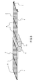
- the figure 1 shows an example of known rigid P solar panels device, intended to be deployed on either side of the body of a spacecraft S, in the configuration stored under the cap C of a launcher and in deployed configuration.
- the rigid solar panels P have under C headgear a large size and not optimized compared to the volume allocated under the cover C.
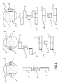
- the figure 2 shows a diagram of an exemplary device according to the invention.
- the latter comprises a flexible membrane 2, supporting a plurality of photovoltaic cells, a plurality of meter-ribbons 1 constituting a supporting structure.
- said membrane 2 may be semi-rigid, or consist of flexible and rigid elements such as thin flat slats flexibly connected to each other.
- the tape measures 1 are preferably wrapped around their natural radius of curvature.
- a mandrel 11 may be present, essentially to provide a winding support function for the flexible membrane 2.
- two meter-ribbons 1 support the flexible membrane 2. Said meter-ribbons 1, are connected by transverse slats 5 to ensure the rigidity of the supporting structure of the flexible membrane 2.
- the meter-ribbons 1 can be positioned in different configurations depending on the need for stiffness in the deployed configuration.
- the meter-ribbons 1 are preferably wound with their curved face outwards, as shown in FIG. figure 2 but it is also possible to have a winding with domed side facing inwards. This is particularly the usual practice for some meter-bistable ribbons.
- the device according to the invention may comprise two similar structures, windable, whose winding mandrels 11 are substantially parallel.
- the two structures can be deployed simultaneously via a system of rotation of the mandrels 11 possibly combined with a heating system of the tape meters 1.
- the two membranes can be mounted on the mandrel tangentially or radially, so as to be positioned on single or parallel planes.
- the supporting structure consisting of a plurality of tape-meters 1 comprises in fact at least one main tape-measure and at least one conventional secondary tape-measure, in metal or composite material, the secondary tape-tapes having the function of driving the deployment of the membranes due to their natural tendency to unfold and the main tape-ribbons having the functions of maintaining the membranes in rolled-up position before deployment and the regulation of the deployment by means of actuations.
- These deployment systems can be coupled to a system allowing the rotation of the mandrel 11 at the same time as the deployment of the membrane or membranes 2.
- the at least one main tape measure combines a composite material and a layer of a material having a high variation in rigidity when crossing a temperature threshold, for example a thermoplastic material, and the actuating means are thermal.
- the at least one main tape measure may be of bistable type and include a layer of material having a strong variation of rigidity when crossing a temperature threshold, the actuating means being thermal.
- the figure 4 illustrates various configurations under cover and deployed devices for deployment of solar generators according to the invention.
- the wound state of the membranes 2 supported by a tape-supporting structure is compact.
- the main advantage of the invention is to propose a solution for the deployment of large solar generators, using a simple and especially compact mechanism.
Description
- Le domaine de l'invention est celui des structures déployables dans l'espace pouvant avantageusement être utilisées pour le déploiement de générateurs solaires.
- Les mètre-rubans - tape-spring en anglais - sont connus en tant que tels dans le domaine spatial comme étant des rubans aptes à passer de l'état enroulé à l'état déroulé essentiellement grâce à leur énergie élastique propre ; à l'état déroulé, les mètre-rubans connus présentent généralement une rigidité apte à les maintenir dans cet état, cf.
US 2007/0262204 . - Les mètre-rubans classiques, généralement métalliques, ont donc une tendance naturelle à se déplier pour se retrouver dans leur état stable. Si on les force à se replier, ils ont tendance à le faire sur un rayon égal à celui de leur rayon de courbure transversale. Il faut donc un effort extérieur faible pour les maintenir enroulés sous cette forme. Si cet effort est brutalement supprimé, le dépliement peut être violent et incontrôlé, c'est-à-dire que tout le mètre-ruban peut avoir tendance à se remettre droit simultanément, sur toute sa longueur. Les mètre-rubans classiques peuvent ainsi présenter des difficultés en termes de contrôle de leur dépliement.
- Des mètre-rubans classiques en composite ont par ailleurs été mis au point. Ces derniers ont des propriétés similaires pour l'essentiel à celles des mètre-rubans classiques métallique, mais présentent l'avantage de rendre possible, dans une certaine mesure, le contrôle de leur rayon d'enroulement propre. Ils offrent également l'avantage d'un rapport rigidité / masse élevé ainsi que d'un faible coefficient de dilatation.
- La demanderesse a déjà démontré que l'on peut associer un mètre-ruban classique à une couche de matériau thermoplastique.. Cette invention a fait l'objet de la demande de brevet
FR 0803986 - Enfin, par construction, il est possible de rendre un mètre-ruban composite bi-stable. Des études ont été publiées sur cette question, comme notamment « Carbon Fibre Reinforced Plastic Tape Springs », J.C.H. Yee et AI., AIAA 2004-1819, et « Analytical models for bistable cylindrical shells », S.D. Guest et AI.
- La propriété remarquable des mètre-rubans bi-stables réside dans le fait qu'ils sont mécaniquement stables à la fois à l'état déroulé et à l'état enroulé. L'état le plus stable reste cependant l'état déroulé. Les mètre-rubans bi-stables sont enroulés par l'intermédiaire d'un effort généralement important. Ils restent stables à l'état enroulés autour de leur rayon de courbure naturel, sans effort extérieur. Il suffit d'en déplier une extrémité, avec un effort de faible intensité, exercé par un système de motorisation par exemple, pour déclencher le déroulement. Le déroulement peut être très rapide, mais reste progressif à partir du point de déroulement initial.
- La problématique générale à laquelle a trait l'invention réside dans le déploiement de générateurs solaires de grande dimension et au problème d'encombrement sous la coiffe des lanceurs qui en découle.
- Il existe de nombreuses possibilités technologiques pour déployer de vastes générateurs solaires dans l'espace, telles que celles décrites dans les brevets
US 6555740 , où la structure portante et la membrane supportant les cellules photovoltaïques de générateurs solaires sont déployés séparément, ou le brevetUS 6543725 , où la structure portante est pliée (et non enroulée). - La présente invention constitue une alternative technologique à ces solutions connues, présentant l'avantage d'être moins encombrante, et de rendre possible un contrôle plus fin du déploiement de générateurs solaires de grande dimension.
- L'état de la technique comprend par ailleurs un dispositif pour le déploiement de panneaux stockés en accordéon et déployables à l'aide d'un tube composite polymérisé et gonflable. Cependant, ce type de dispositif n'est utilisable qu'une seule fois, car la polymérisation est irréversible. Ceci pose un problème pour démontrer et valider le déploiement complet au sol avant d'être envoyé dans l'espace.
- Un but de l'invention est notamment de pallier les inconvénients précités. Pour assurer le déploiement de générateurs solaires de grande dimension, elle propose l'utilisation d'une structure comprenant des mètre-rubans en parallèle, sur lesquels est fixée une membrane souple, semi-rigide, ou composée d'éléments souples et rigides tels que de fines lattes planes reliées de manière flexibles entre elles, ladite membrane ayant une face sur laquelle sont agencées une pluralité d'éléments aptes à transformer l'énergie solaire en énergie électrique.
- Plus précisément, l'invention a pour objet un dispositif de déploiement de générateur solaire comprenant un ensemble comprenant une pluralité de mètre-rubans supportant une membrane enroulable sur une face de laquelle est agencée une pluralité d'éléments aptes à transformer l'énergie solaire en énergie électrique, à l'état enroulé lesdits mètre-rubans et ladite membrane étant co-enroulés autour d'un rayon de courbure unique égal au rayon de courbure de pliage du mètre-ruban et en ce que lesdits mètres rubans sont sensiblement parallèles et reliés entre eux par des lattes transversales assurant la rigidité de la structure porteuse.
- Ledit ensemble comprend :
- au moins un mètre-ruban principal ayant pour fonction le maintien de la membrane en position enroulée avant le déploiement et la régulation du déploiement,
- au moins un mètre-ruban secondaire, en métal ou en matériau composite, ayant pour fonction la motorisation du déploiement de la membrane du fait de leur tendance naturelle à se déplier.
- L'au moins un mètre-ruban principal (1) associe un matériau composite et une couche d'un matériau présentant une variation de rigidité lors du franchissement d'un seuil de température.
- Avantageusement, l'au moins un mètre-ruban principal associe un matériau composite et une couche thermoplastique, thermiques.
- Avantageusement l'au moins un mètre-ruban principal est de type bistable et comprend en outre une couche d'un matériau présentant une forte variation de rigidité lors du franchissement d'un seuil de température et en ce que les moyens d'actionnements sont thermiques. Avantageusement, ledit ensemble et la membrane peuvent être co-enroulés autour d'un mandrin de rayon préférentiellement supérieur ou égal au rayon de courbure naturel dudit mètre-ruban.
- Avantageusement, ladite membrane peut être souple.
- Avantageusement, ladite membrane peut être composée d'éléments souples et rigides.
- Avantageusement, lesdits éléments souples et rigides consistent en de fines lattes planes liées entre elles de manière flexible.
- Avantageusement, lesdits éléments aptes à transformer l'énergie solaire et énergie électrique peuvent être des cellules photovoltaïques souples.
- Avantageusement, les cellules photovoltaïques souples sont en AsGa.
- Avantageusement, ledit au moins mètre-ruban présente une face bombée et en ce qu'il est enroulé indifféremment avec la face bombée vers l'extérieur ou la face bombée vers l'intérieur.
- D'autres caractéristiques et avantages de l'invention apparaîtront à l'aide de la description qui suit faite en regard des dessins annexés qui représentent :
- la
figure 1 : un générateur solaire rigide en configuration stockée sous coiffe d'un lanceur et en configuration déployé, selon l'art connu ; - la
figure 2 : un exemple de dispositif selon l'invention, comprenant des générateurs solaires à une membrane revêtue de cellules photovoltaïques, en cours de déploiement ; - la
figure 3 : le même exemple de dispositif selon l'invention, mais à double membranes et en configuration déployée ; - la
figure 4 : des exemples de configuration sous coiffe de dispositifs selon l'invention, en fonction de différents modes de réalisation. - La
figure 1 présente un exemple de dispositif de panneaux solaires P rigides connus, destinés à être déployés de part et d'autre de la caisse d'un engin spatial S, en configuration stocké sous la coiffe C d'un lanceur et en configuration déployée. Comme évoqué précédemment, les panneaux solaires rigides P présentent sous coiffe C un encombrement important et non optimisé par rapport au volume alloué sous la coiffe C. - La
figure 2 présente un schéma d'un exemple de dispositif selon l'invention. Ce dernier comprend une membrane souple 2, supportant une pluralité de cellules photovoltaïques, une pluralité de mètre-rubans 1 constituant une structure portante. Alternativement, ladite membrane 2 peut être semi-rigide, ou être constituée d'éléments souples et rigides tels que de fines lattes planes reliées de manière flexibles entres elles. - A l'état enroulé, les mètre-rubans 1 sont de préférence enroulés autour de leur rayon de courbure naturel. Un mandrin 11 peut être présent, essentiellement pour assurer une fonction de support d'enroulement pour la membrane souple 2.
- Dans le mode de réalisation représenté sur les
figures 2 et3 , deux mètre-rubans 1 supportent la membrane souple 2. Lesdits mètre-rubans 1, sont reliés par des lattes transversales 5 afin d'assurer la rigidité de la structure porteuse de la membrane souple 2. Les mètre-rubans 1 peuvent êtres positionnés dans différentes configurations en fonction du besoin en raideur en configuration déployée. Les mètre-rubans 1 sont préférentiellement enroulés avec leur face bombée vers l'extérieur, comme représenté dans lafigure 2 , mais il est également possible d'avoir un enroulement avec face bombée vers l'intérieur. C'est notamment la pratique habituelle pour certains mètre-rubans bistables. - Comme représenté à la
figure 3 , dans un stade de déploiement plus avancé, le dispositif selon l'invention peut comporter deux structures similaires, enroulables, dont les mandrins d'enroulement 11 sont sensiblement parallèles. Avantageusement, les deux structures peuvent êtres déployées simultanément par l'intermédiaire d'un système de rotation des mandrins 11 éventuellement combiné à un système de réchauffage des mètres à rubans 1. En configuration déployée, les deux membranes peuvent être montées sur le mandrin tangentiellement ou radialement, de manière à être positionné sur des plans uniques ou parallèles. - Dans le mode de réalisation préférée de l'invention, pour la membrane souple 2, la structure portante constituée d'une pluralité de mètre-rubans 1 comprend en fait au moins un mètre-ruban principal et au moins un mètre-ruban secondaire classique, en métal ou en matériau composite, les mètre-rubans secondaires ayant pour fonction la motorisation du déploiement des membranes du fait de leur tendance naturelle à se déplier et les mètre-rubans principaux ayant pour fonctions le maintien des membranes en position enroulée avant le déploiement et la régulation du déploiement au moyen d'actionnements. Ces systèmes de déploiement peuvent êtres couplés à un système permettant la rotation du mandrin 11 en même temps que s'effectue le déploiement de la ou des membranes 2.
- L'au moins un mètre ruban principal associe un matériau composite et une couche d'un matériau présentant une forte variation de rigidité lors du franchissement d'un seuil de température, par exemple un matériau thermoplastique, et les moyens d'actionnement sont thermiques.
- Alternativement, l'au moins un mètre ruban principal peut être de type bistable et comprendre une couche de matériau présentant une forte variation de rigidité lors du franchissement d'un seuil de température, les moyens d'actionnement étant thermiques.
- La
figure 4 illustre différentes configurations sous coiffe et déployés de dispositifs de déploiement de générateurs solaires selon l'invention. En position stockée, comme le montrent les schémas de lafigure 4 , l'état enroulé des membranes 2 supportées par une structure portante de mètre-rubans est peu encombrant. - En résumé, l'invention a pour principal avantage de proposer une solution pour le déploiement de générateurs solaires de grande dimension, à l'aide d'un mécanisme simple et surtout compact.
Claims (9)
- Dispositif de déploiement de générateur solaire comprenant :- un ensemble comprenant une pluralité de mètre-rubans (1) supportant une membrane (2) enroulable sur une face de laquelle est agencée une pluralité d'éléments aptes à transformer l'énergie solaire en énergie électrique, et- à l'état enroulé lesdits mètre-rubans (1) et ladite membrane (2) sont co-enroulés autour d'un rayon de courbure unique égal au rayon de courbure de pliage du mètre-ruban (1),- lesdits mètres rubans étant sensiblement parallèles et reliés entre eux par des lattes transversales (5) assurant la rigidité de la structure porteuse,caractérisé en ce que le dit ensemble comprend :- au moins un mètre-ruban principal (1), ayant pour fonction le maintien de la membrane (2) en position enroulée avant le déploiement et le contrôle du déploiement, ledit mètre ruban principal associant un matériau composite et une couche d'un matériau présentant une variation de rigidité lors du franchissement d'un seuil de température,- au moins un mètre-ruban secondaire en métal ou en matériau composite, ayant pour fonction la motorisation du déploiement de la membrane (2) du fait de leur tendance naturelle à se déplier.
- Dispositif selon la revendication 1, caractérisé en ce que l'au moins un mètre-ruban principal (1) associe un matériau composite et une couche thermoplastique.
- Dispositif selon l'une des revendications précédentes, caractérisé en ce que ledit ensemble et la membrane (2) sont co-enroulés autour d'un mandrin (11).
- Dispositif selon l'une des revendications précédentes caractérisé en ce que lesdits éléments aptes à transformer l'énergie solaire en énergie électrique sont des cellules photovoltaïques souples.
- Dispositif selon la revendication 4 caractérisé en ce que lesdites cellules photovoltaïques souples sont en AsGa.
- Dispositif selon l'une des revendications précédentes, caractérisé en ce que ladite membrane (2) est souple.
- Dispositif selon l'une des revendications précédentes, caractérisé en ce que ladite membrane (2) est composée d'éléments souples et rigides.
- Dispositif selon la revendication 7, caractérisé en ce que lesdits éléments souples et rigides consistent en de fines lattes planes liées entre elles de manière flexible.
- Dispositif selon l'une des revendications précédentes, caractérisé en ce que lesdits mètre-rubans (1) présentent une face bombée et en ce qu'ils sont enroulés indifféremment avec la face bombée vers l'extérieur ou la face bombée vers l'intérieur.
Applications Claiming Priority (1)
| Application Number | Priority Date | Filing Date | Title |
|---|---|---|---|
| FR1005184A FR2969985B1 (fr) | 2010-12-30 | 2010-12-30 | Générateur solaire plan deroulable |
Publications (2)
| Publication Number | Publication Date |
|---|---|
| EP2471714A1 EP2471714A1 (fr) | 2012-07-04 |
| EP2471714B1 true EP2471714B1 (fr) | 2015-01-28 |
Family
ID=44260833
Family Applications (1)
| Application Number | Title | Priority Date | Filing Date |
|---|---|---|---|
| EP11192099.7A Not-in-force EP2471714B1 (fr) | 2010-12-30 | 2011-12-06 | Générateur solaire plan deroulable |
Country Status (5)
| Country | Link |
|---|---|
| US (1) | US20120167943A1 (fr) |
| EP (1) | EP2471714B1 (fr) |
| JP (1) | JP2012140120A (fr) |
| ES (1) | ES2535336T3 (fr) |
| FR (1) | FR2969985B1 (fr) |
Families Citing this family (22)
| Publication number | Priority date | Publication date | Assignee | Title |
|---|---|---|---|---|
| US8683755B1 (en) | 2010-01-21 | 2014-04-01 | Deployable Space Systems, Inc. | Directionally controlled elastically deployable roll-out solar array |
| FR2998876B1 (fr) * | 2012-12-05 | 2015-07-17 | Thales Sa | Dispositif de deploiement et de reploiement d'une structure flexible, structure deployable flexible et satellite munis d'un tel dispositif |
| US8894017B1 (en) * | 2012-12-28 | 2014-11-25 | Space Systems/Loral, Llc | Flexible array support structure |
| US9352855B2 (en) * | 2013-04-09 | 2016-05-31 | Lockheed Martin Corporation | Heat generating transfer orbit shield |
| JP5714661B2 (ja) * | 2013-07-12 | 2015-05-07 | 中国電力株式会社 | 絶縁防護カバー |
| EP2827380A1 (fr) * | 2013-07-19 | 2015-01-21 | Emcore Solar Power, Inc. | Système d'énergie solaire pour véhicules spatiaux ou satellites utilisant des cellules solaires multijonctions métamorphiques inversées |
| FR3024228B1 (fr) * | 2014-07-25 | 2018-02-09 | Thales | Structure deployable a metre-ruban |
| US9856039B2 (en) * | 2014-10-08 | 2018-01-02 | Analytical Mechanics Associates, Inc. | Extendable solar array for a spacecraft system |
| US9004410B1 (en) | 2014-10-24 | 2015-04-14 | Alliance Spacesystems, Llc | Deployable boom for collecting electromagnetic energy |
| US20160137319A1 (en) * | 2014-10-24 | 2016-05-19 | Solaero Technologies Corp. | Method for releasing a deployable boom |
| US10059471B2 (en) | 2014-10-24 | 2018-08-28 | Solaero Technologies Corp. | Method for releasing a deployable boom |
| US10189583B2 (en) * | 2015-05-13 | 2019-01-29 | Analytical Mechanics Associates, Inc. | Deployable sheet material systems and methods |
| WO2016197094A1 (fr) | 2015-06-04 | 2016-12-08 | Total Shade Inc. | Système d'isolation de fenêtre et de production d'énergie |
| FR3041816B1 (fr) * | 2015-09-25 | 2017-10-20 | Thales Sa | Generateur solaire flexible muni d'une protection electrique contre des impacts d'objets celestes, engin spatial et satellite comportant au moins un tel generateur solaire |
| CN106005479B (zh) * | 2016-06-07 | 2018-05-04 | 北京空间飞行器总体设计部 | 一种可用于大变形杆件的大收纳比展开装置 |
| CN106785311B (zh) * | 2017-02-23 | 2019-03-01 | 哈尔滨工业大学 | 天基雷达可折叠展开天线反射面折展结构 |
| CN109586665B (zh) * | 2019-01-17 | 2024-03-01 | 浙江工业大学 | 一种具有双稳态特性可折叠的太阳能板 |
| WO2020150735A1 (fr) | 2019-01-18 | 2020-07-23 | M.M.A. Design, LLC | Système déployable à membrane souple |
| FR3101065B1 (fr) * | 2019-09-19 | 2021-11-26 | Thales Sa | Dispositif deployable |
| CN111717719B (zh) * | 2020-05-31 | 2021-11-02 | 东南大学 | 多边形棱柱薄膜结构折叠工装系统及折叠方法 |
| US11936335B2 (en) * | 2021-07-30 | 2024-03-19 | Momentus Space Llc | Rollable tape spring solar array |
| CN114435628A (zh) * | 2022-01-12 | 2022-05-06 | 航天科工空间工程发展有限公司 | 一种空间展开机构 |
Family Cites Families (20)
| Publication number | Priority date | Publication date | Assignee | Title |
|---|---|---|---|---|
| FR803986A (fr) | 1935-07-03 | 1936-10-13 | épingle pour fixer les tôles avant rivetage | |
| DE1956052A1 (de) * | 1969-11-07 | 1971-05-13 | Erno Raumfahrttechnik Gmbh | Raumflugkoerper mit Auslegern |
| FR2350695A1 (fr) * | 1976-05-03 | 1977-12-02 | Aerospatiale | Generateur solaire d'energie electrique |
| JPS58136900U (ja) * | 1982-03-11 | 1983-09-14 | 三菱電機株式会社 | 太陽電池パネル |
| US4636579A (en) * | 1985-03-18 | 1987-01-13 | Energy Conversion Devices, Inc. | Retractable power supply |
| JP2647040B2 (ja) * | 1994-11-30 | 1997-08-27 | 日本電気株式会社 | サンシールド |
| JP3027116B2 (ja) * | 1996-02-28 | 2000-03-27 | 株式会社日立製作所 | 太陽電池 |
| JPH10129600A (ja) * | 1996-10-31 | 1998-05-19 | Nec Eng Ltd | 太陽電池パドル |
| DE19836272C2 (de) | 1998-08-11 | 2003-08-07 | Astrium Gmbh | Flexibler, faltbarer Solargenerator für Raumflugkörper |
| DE10048846C1 (de) | 2000-10-02 | 2001-09-13 | Astrium Gmbh | Ausfahrbarer Solargenerator mit ausfahrbarer Trägerstruktur |
| US6904722B2 (en) * | 2001-02-21 | 2005-06-14 | The United States Of America As Represented By The Secretary Of The Navy | Elongated truss boom structures for space applications |
| JP3768474B2 (ja) * | 2002-12-17 | 2006-04-19 | 川崎重工業株式会社 | 太陽電池パドルの展開構造及び人工衛星 |
| US7678990B2 (en) * | 2004-02-17 | 2010-03-16 | Elk Premium Building Products, Inc. | Flexible integrated photovoltaic roofing membrane and related methods of manufacturing same |
| KR20070104582A (ko) * | 2005-01-04 | 2007-10-26 | 쟈끄 람베이 | 광 발전 블라인드 또는 차양 |
| FR2896636B1 (fr) * | 2006-01-20 | 2008-02-29 | Alcatel Sa | Generateur solaire a concentrateur d'arcs electriques primaires |
| JP4762753B2 (ja) * | 2006-02-17 | 2011-08-31 | シャープ株式会社 | 薄膜単結晶化合物太陽電池の製造方法 |
| US7806370B2 (en) * | 2006-03-31 | 2010-10-05 | Composite Technology Development, Inc. | Large-scale deployable solar array |
| JP2008238863A (ja) * | 2007-03-26 | 2008-10-09 | Aisin Seiki Co Ltd | シェード取付け構造 |
| FR2933771B1 (fr) * | 2008-07-11 | 2010-08-13 | Thales Sa | Metre ruban a deploiement thermique et structure deployable comportant ledit metre ruban |
| FR2969984B1 (fr) * | 2010-12-30 | 2013-02-08 | Thales Sa | Générateur solaire deroulable caissonne |
-
2010
- 2010-12-30 FR FR1005184A patent/FR2969985B1/fr not_active Expired - Fee Related
-
2011
- 2011-12-06 EP EP11192099.7A patent/EP2471714B1/fr not_active Not-in-force
- 2011-12-06 ES ES11192099.7T patent/ES2535336T3/es active Active
- 2011-12-23 US US13/336,878 patent/US20120167943A1/en not_active Abandoned
- 2011-12-27 JP JP2011286165A patent/JP2012140120A/ja active Pending
Also Published As
| Publication number | Publication date |
|---|---|
| EP2471714A1 (fr) | 2012-07-04 |
| FR2969985A1 (fr) | 2012-07-06 |
| US20120167943A1 (en) | 2012-07-05 |
| JP2012140120A (ja) | 2012-07-26 |
| ES2535336T3 (es) | 2015-05-08 |
| FR2969985B1 (fr) | 2016-09-09 |
Similar Documents
| Publication | Publication Date | Title |
|---|---|---|
| EP2471714B1 (fr) | Générateur solaire plan deroulable | |
| EP2471713B1 (fr) | Générateur solaire déroulable caissonné | |
| EP2977322B1 (fr) | Procédé d'encastrement escamotable de mètre-ruban pour une structure déployable et structure déployable à mètre-ruban | |
| EP2977323B1 (fr) | Structure déployable à mètre-ruban | |
| EP3023333B1 (fr) | Structure déployable escamotable à mètre-ruban | |
| CA2933347C (fr) | Voilure gonflable deployable | |
| US9611056B1 (en) | Directionally controlled elastically deployable roll-out solar array | |
| FR2933771A1 (fr) | Metre ruban a deploiement thermique et structure deployable comportant ledit metre ruban | |
| EP1873061B1 (fr) | Structure déployable comportant des éléments rigides, embarquée sur un engin spatial | |
| EP2301112A2 (fr) | Structure articulee deployable | |
| FR2584045A1 (fr) | Grand panneau solaire a frequence propre elevee pour satellite | |
| EP3326920A1 (fr) | Structure déployable à déploiement spontané | |
| EP1805081A1 (fr) | Dispositif de commande du deploiement de structures gonflables | |
| EP3079987B1 (fr) | Nouvelle architecture de véhicule spatial | |
| EP2724944A2 (fr) | Système de motorisation pour articulation à moyens d'enroulement croisés avec roulement fiabilisé | |
| EP2724945A2 (fr) | Système de motorisation pour articulation à pistes de roulement flexibles | |
| EP2415117B1 (fr) | Antenne radioelectrique comportant des moyens de rigidification améliorés | |
| FR3020096A1 (fr) | Eolienne adaptative | |
| EP3910739A1 (fr) | Antenne radiofréquence auto-déployable | |
| EP2307277B1 (fr) | Mât déployable à ossature repliée spontanément déployable et rigide à l'état déployé | |
| WO2015092160A1 (fr) | Structure segmentée, en particulier pour réflecteur d'antenne de satellite. pourvue d'au moins un dispositif de déploiement à ruban | |
| WO2010004169A2 (fr) | Mât déployable à ossature repliée déployable se verrouillant par construction à l'état déployé |
Legal Events
| Date | Code | Title | Description |
|---|---|---|---|
| AK | Designated contracting states |
Kind code of ref document: A1 Designated state(s): AL AT BE BG CH CY CZ DE DK EE ES FI FR GB GR HR HU IE IS IT LI LT LU LV MC MK MT NL NO PL PT RO RS SE SI SK SM TR |
|
| AX | Request for extension of the european patent |
Extension state: BA ME |
|
| PUAI | Public reference made under article 153(3) epc to a published international application that has entered the european phase |
Free format text: ORIGINAL CODE: 0009012 |
|
| 17P | Request for examination filed |
Effective date: 20121206 |
|
| 17Q | First examination report despatched |
Effective date: 20130208 |
|
| GRAP | Despatch of communication of intention to grant a patent |
Free format text: ORIGINAL CODE: EPIDOSNIGR1 |
|
| INTG | Intention to grant announced |
Effective date: 20141017 |
|
| GRAS | Grant fee paid |
Free format text: ORIGINAL CODE: EPIDOSNIGR3 |
|
| GRAA | (expected) grant |
Free format text: ORIGINAL CODE: 0009210 |
|
| AK | Designated contracting states |
Kind code of ref document: B1 Designated state(s): AL AT BE BG CH CY CZ DE DK EE ES FI FR GB GR HR HU IE IS IT LI LT LU LV MC MK MT NL NO PL PT RO RS SE SI SK SM TR |
|
| REG | Reference to a national code |
Ref country code: GB Ref legal event code: FG4D Free format text: NOT ENGLISH |
|
| REG | Reference to a national code |
Ref country code: CH Ref legal event code: EP |
|
| REG | Reference to a national code |
Ref country code: IE Ref legal event code: FG4D Free format text: LANGUAGE OF EP DOCUMENT: FRENCH |
|
| REG | Reference to a national code |
Ref country code: DE Ref legal event code: R096 Ref document number: 602011013493 Country of ref document: DE Effective date: 20150312 |
|
| REG | Reference to a national code |
Ref country code: AT Ref legal event code: REF Ref document number: 708114 Country of ref document: AT Kind code of ref document: T Effective date: 20150315 |
|
| REG | Reference to a national code |
Ref country code: CH Ref legal event code: NV Representative=s name: MARKS AND CLERK (LUXEMBOURG) LLP, CH |
|
| REG | Reference to a national code |
Ref country code: ES Ref legal event code: FG2A Ref document number: 2535336 Country of ref document: ES Kind code of ref document: T3 Effective date: 20150508 |
|
| REG | Reference to a national code |
Ref country code: SE Ref legal event code: TRGR |
|
| REG | Reference to a national code |
Ref country code: LT Ref legal event code: MG4D |
|
| PG25 | Lapsed in a contracting state [announced via postgrant information from national office to epo] |
Ref country code: LT Free format text: LAPSE BECAUSE OF FAILURE TO SUBMIT A TRANSLATION OF THE DESCRIPTION OR TO PAY THE FEE WITHIN THE PRESCRIBED TIME-LIMIT Effective date: 20150128 Ref country code: NO Free format text: LAPSE BECAUSE OF FAILURE TO SUBMIT A TRANSLATION OF THE DESCRIPTION OR TO PAY THE FEE WITHIN THE PRESCRIBED TIME-LIMIT Effective date: 20150428 Ref country code: HR Free format text: LAPSE BECAUSE OF FAILURE TO SUBMIT A TRANSLATION OF THE DESCRIPTION OR TO PAY THE FEE WITHIN THE PRESCRIBED TIME-LIMIT Effective date: 20150128 Ref country code: FI Free format text: LAPSE BECAUSE OF FAILURE TO SUBMIT A TRANSLATION OF THE DESCRIPTION OR TO PAY THE FEE WITHIN THE PRESCRIBED TIME-LIMIT Effective date: 20150128 Ref country code: BG Free format text: LAPSE BECAUSE OF FAILURE TO SUBMIT A TRANSLATION OF THE DESCRIPTION OR TO PAY THE FEE WITHIN THE PRESCRIBED TIME-LIMIT Effective date: 20150428 |
|
| PG25 | Lapsed in a contracting state [announced via postgrant information from national office to epo] |
Ref country code: GR Free format text: LAPSE BECAUSE OF FAILURE TO SUBMIT A TRANSLATION OF THE DESCRIPTION OR TO PAY THE FEE WITHIN THE PRESCRIBED TIME-LIMIT Effective date: 20150429 Ref country code: RS Free format text: LAPSE BECAUSE OF FAILURE TO SUBMIT A TRANSLATION OF THE DESCRIPTION OR TO PAY THE FEE WITHIN THE PRESCRIBED TIME-LIMIT Effective date: 20150128 Ref country code: IS Free format text: LAPSE BECAUSE OF FAILURE TO SUBMIT A TRANSLATION OF THE DESCRIPTION OR TO PAY THE FEE WITHIN THE PRESCRIBED TIME-LIMIT Effective date: 20150528 Ref country code: LV Free format text: LAPSE BECAUSE OF FAILURE TO SUBMIT A TRANSLATION OF THE DESCRIPTION OR TO PAY THE FEE WITHIN THE PRESCRIBED TIME-LIMIT Effective date: 20150128 Ref country code: PL Free format text: LAPSE BECAUSE OF FAILURE TO SUBMIT A TRANSLATION OF THE DESCRIPTION OR TO PAY THE FEE WITHIN THE PRESCRIBED TIME-LIMIT Effective date: 20150128 |
|
| REG | Reference to a national code |
Ref country code: DE Ref legal event code: R097 Ref document number: 602011013493 Country of ref document: DE |
|
| PG25 | Lapsed in a contracting state [announced via postgrant information from national office to epo] |
Ref country code: EE Free format text: LAPSE BECAUSE OF FAILURE TO SUBMIT A TRANSLATION OF THE DESCRIPTION OR TO PAY THE FEE WITHIN THE PRESCRIBED TIME-LIMIT Effective date: 20150128 Ref country code: RO Free format text: LAPSE BECAUSE OF FAILURE TO SUBMIT A TRANSLATION OF THE DESCRIPTION OR TO PAY THE FEE WITHIN THE PRESCRIBED TIME-LIMIT Effective date: 20150128 Ref country code: SK Free format text: LAPSE BECAUSE OF FAILURE TO SUBMIT A TRANSLATION OF THE DESCRIPTION OR TO PAY THE FEE WITHIN THE PRESCRIBED TIME-LIMIT Effective date: 20150128 Ref country code: DK Free format text: LAPSE BECAUSE OF FAILURE TO SUBMIT A TRANSLATION OF THE DESCRIPTION OR TO PAY THE FEE WITHIN THE PRESCRIBED TIME-LIMIT Effective date: 20150128 Ref country code: CZ Free format text: LAPSE BECAUSE OF FAILURE TO SUBMIT A TRANSLATION OF THE DESCRIPTION OR TO PAY THE FEE WITHIN THE PRESCRIBED TIME-LIMIT Effective date: 20150128 |
|
| REG | Reference to a national code |
Ref country code: FR Ref legal event code: PLFP Year of fee payment: 5 |
|
| PLBE | No opposition filed within time limit |
Free format text: ORIGINAL CODE: 0009261 |
|
| STAA | Information on the status of an ep patent application or granted ep patent |
Free format text: STATUS: NO OPPOSITION FILED WITHIN TIME LIMIT |
|
| 26N | No opposition filed |
Effective date: 20151029 |
|
| PGFP | Annual fee paid to national office [announced via postgrant information from national office to epo] |
Ref country code: GB Payment date: 20151202 Year of fee payment: 5 Ref country code: DE Payment date: 20151201 Year of fee payment: 5 Ref country code: CH Payment date: 20151211 Year of fee payment: 5 |
|
| PG25 | Lapsed in a contracting state [announced via postgrant information from national office to epo] |
Ref country code: SI Free format text: LAPSE BECAUSE OF FAILURE TO SUBMIT A TRANSLATION OF THE DESCRIPTION OR TO PAY THE FEE WITHIN THE PRESCRIBED TIME-LIMIT Effective date: 20150128 |
|
| PGFP | Annual fee paid to national office [announced via postgrant information from national office to epo] |
Ref country code: NL Payment date: 20151210 Year of fee payment: 5 Ref country code: ES Payment date: 20151127 Year of fee payment: 5 Ref country code: FR Payment date: 20151123 Year of fee payment: 5 Ref country code: SE Payment date: 20151211 Year of fee payment: 5 |
|
| PGFP | Annual fee paid to national office [announced via postgrant information from national office to epo] |
Ref country code: IT Payment date: 20151221 Year of fee payment: 5 |
|
| PG25 | Lapsed in a contracting state [announced via postgrant information from national office to epo] |
Ref country code: BE Free format text: LAPSE BECAUSE OF NON-PAYMENT OF DUE FEES Effective date: 20151231 |
|
| PG25 | Lapsed in a contracting state [announced via postgrant information from national office to epo] |
Ref country code: LU Free format text: LAPSE BECAUSE OF FAILURE TO SUBMIT A TRANSLATION OF THE DESCRIPTION OR TO PAY THE FEE WITHIN THE PRESCRIBED TIME-LIMIT Effective date: 20151206 Ref country code: MC Free format text: LAPSE BECAUSE OF FAILURE TO SUBMIT A TRANSLATION OF THE DESCRIPTION OR TO PAY THE FEE WITHIN THE PRESCRIBED TIME-LIMIT Effective date: 20150128 |
|
| REG | Reference to a national code |
Ref country code: AT Ref legal event code: UEP Ref document number: 708114 Country of ref document: AT Kind code of ref document: T Effective date: 20150128 |
|
| REG | Reference to a national code |
Ref country code: IE Ref legal event code: MM4A |
|
| PG25 | Lapsed in a contracting state [announced via postgrant information from national office to epo] |
Ref country code: IE Free format text: LAPSE BECAUSE OF NON-PAYMENT OF DUE FEES Effective date: 20151206 |
|
| PG25 | Lapsed in a contracting state [announced via postgrant information from national office to epo] |
Ref country code: SM Free format text: LAPSE BECAUSE OF FAILURE TO SUBMIT A TRANSLATION OF THE DESCRIPTION OR TO PAY THE FEE WITHIN THE PRESCRIBED TIME-LIMIT Effective date: 20150128 Ref country code: HU Free format text: LAPSE BECAUSE OF FAILURE TO SUBMIT A TRANSLATION OF THE DESCRIPTION OR TO PAY THE FEE WITHIN THE PRESCRIBED TIME-LIMIT; INVALID AB INITIO Effective date: 20111206 |
|
| PG25 | Lapsed in a contracting state [announced via postgrant information from national office to epo] |
Ref country code: CY Free format text: LAPSE BECAUSE OF FAILURE TO SUBMIT A TRANSLATION OF THE DESCRIPTION OR TO PAY THE FEE WITHIN THE PRESCRIBED TIME-LIMIT Effective date: 20150128 |
|
| REG | Reference to a national code |
Ref country code: DE Ref legal event code: R119 Ref document number: 602011013493 Country of ref document: DE |
|
| REG | Reference to a national code |
Ref country code: CH Ref legal event code: PL |
|
| REG | Reference to a national code |
Ref country code: SE Ref legal event code: EUG |
|
| REG | Reference to a national code |
Ref country code: NL Ref legal event code: MM Effective date: 20170101 |
|
| GBPC | Gb: european patent ceased through non-payment of renewal fee |
Effective date: 20161206 |
|
| PG25 | Lapsed in a contracting state [announced via postgrant information from national office to epo] |
Ref country code: MT Free format text: LAPSE BECAUSE OF FAILURE TO SUBMIT A TRANSLATION OF THE DESCRIPTION OR TO PAY THE FEE WITHIN THE PRESCRIBED TIME-LIMIT Effective date: 20150128 Ref country code: TR Free format text: LAPSE BECAUSE OF FAILURE TO SUBMIT A TRANSLATION OF THE DESCRIPTION OR TO PAY THE FEE WITHIN THE PRESCRIBED TIME-LIMIT Effective date: 20150128 Ref country code: SE Free format text: LAPSE BECAUSE OF NON-PAYMENT OF DUE FEES Effective date: 20161207 |
|
| PG25 | Lapsed in a contracting state [announced via postgrant information from national office to epo] |
Ref country code: NL Free format text: LAPSE BECAUSE OF NON-PAYMENT OF DUE FEES Effective date: 20170101 |
|
| REG | Reference to a national code |
Ref country code: FR Ref legal event code: ST Effective date: 20170831 |
|
| PG25 | Lapsed in a contracting state [announced via postgrant information from national office to epo] |
Ref country code: IT Free format text: LAPSE BECAUSE OF NON-PAYMENT OF DUE FEES Effective date: 20161206 Ref country code: CH Free format text: LAPSE BECAUSE OF NON-PAYMENT OF DUE FEES Effective date: 20161231 Ref country code: LI Free format text: LAPSE BECAUSE OF NON-PAYMENT OF DUE FEES Effective date: 20161231 Ref country code: FR Free format text: LAPSE BECAUSE OF NON-PAYMENT OF DUE FEES Effective date: 20170102 |
|
| PG25 | Lapsed in a contracting state [announced via postgrant information from national office to epo] |
Ref country code: GB Free format text: LAPSE BECAUSE OF NON-PAYMENT OF DUE FEES Effective date: 20161206 Ref country code: DE Free format text: LAPSE BECAUSE OF NON-PAYMENT OF DUE FEES Effective date: 20170701 |
|
| REG | Reference to a national code |
Ref country code: AT Ref legal event code: MM01 Ref document number: 708114 Country of ref document: AT Kind code of ref document: T Effective date: 20161206 |
|
| PG25 | Lapsed in a contracting state [announced via postgrant information from national office to epo] |
Ref country code: ES Free format text: LAPSE BECAUSE OF NON-PAYMENT OF DUE FEES Effective date: 20161207 Ref country code: AT Free format text: LAPSE BECAUSE OF NON-PAYMENT OF DUE FEES Effective date: 20161206 |
|
| PG25 | Lapsed in a contracting state [announced via postgrant information from national office to epo] |
Ref country code: PT Free format text: LAPSE BECAUSE OF FAILURE TO SUBMIT A TRANSLATION OF THE DESCRIPTION OR TO PAY THE FEE WITHIN THE PRESCRIBED TIME-LIMIT Effective date: 20150128 Ref country code: MK Free format text: LAPSE BECAUSE OF FAILURE TO SUBMIT A TRANSLATION OF THE DESCRIPTION OR TO PAY THE FEE WITHIN THE PRESCRIBED TIME-LIMIT Effective date: 20150128 |
|
| REG | Reference to a national code |
Ref country code: ES Ref legal event code: FD2A Effective date: 20181030 |
|
| PG25 | Lapsed in a contracting state [announced via postgrant information from national office to epo] |
Ref country code: AL Free format text: LAPSE BECAUSE OF FAILURE TO SUBMIT A TRANSLATION OF THE DESCRIPTION OR TO PAY THE FEE WITHIN THE PRESCRIBED TIME-LIMIT Effective date: 20150128 |