EP2724944A2 - Système de motorisation pour articulation à moyens d'enroulement croisés avec roulement fiabilisé - Google Patents
Système de motorisation pour articulation à moyens d'enroulement croisés avec roulement fiabilisé Download PDFInfo
- Publication number
- EP2724944A2 EP2724944A2 EP13189070.9A EP13189070A EP2724944A2 EP 2724944 A2 EP2724944 A2 EP 2724944A2 EP 13189070 A EP13189070 A EP 13189070A EP 2724944 A2 EP2724944 A2 EP 2724944A2
- Authority
- EP
- European Patent Office
- Prior art keywords
- flexible
- flexible track
- winding
- tracks
- track
- Prior art date
- Legal status (The legal status is an assumption and is not a legal conclusion. Google has not performed a legal analysis and makes no representation as to the accuracy of the status listed.)
- Granted
Links
- 238000004804 winding Methods 0.000 title claims abstract description 53
- 230000009975 flexible effect Effects 0.000 claims abstract description 114
- 230000000694 effects Effects 0.000 claims abstract description 3
- 238000005096 rolling process Methods 0.000 claims description 15
- 241000282339 Mustela Species 0.000 claims 1
- 230000007246 mechanism Effects 0.000 description 8
- 238000010586 diagram Methods 0.000 description 4
- 230000036316 preload Effects 0.000 description 3
- 230000035939 shock Effects 0.000 description 3
- 238000011161 development Methods 0.000 description 2
- 230000018109 developmental process Effects 0.000 description 2
- 229910003460 diamond Inorganic materials 0.000 description 2
- 239000010432 diamond Substances 0.000 description 2
- 230000001788 irregular Effects 0.000 description 2
- 230000033001 locomotion Effects 0.000 description 2
- 208000031968 Cadaver Diseases 0.000 description 1
- 230000005611 electricity Effects 0.000 description 1
- 230000003628 erosive effect Effects 0.000 description 1
- 230000001939 inductive effect Effects 0.000 description 1
- 239000000463 material Substances 0.000 description 1
- 238000000034 method Methods 0.000 description 1
- 230000003071 parasitic effect Effects 0.000 description 1
- 230000001737 promoting effect Effects 0.000 description 1
- 230000001105 regulatory effect Effects 0.000 description 1
Images
Classifications
-
- B—PERFORMING OPERATIONS; TRANSPORTING
- B64—AIRCRAFT; AVIATION; COSMONAUTICS
- B64G—COSMONAUTICS; VEHICLES OR EQUIPMENT THEREFOR
- B64G1/00—Cosmonautic vehicles
- B64G1/22—Parts of, or equipment specially adapted for fitting in or to, cosmonautic vehicles
- B64G1/222—Parts of, or equipment specially adapted for fitting in or to, cosmonautic vehicles for deploying structures between a stowed and deployed state
-
- E—FIXED CONSTRUCTIONS
- E04—BUILDING
- E04H—BUILDINGS OR LIKE STRUCTURES FOR PARTICULAR PURPOSES; SWIMMING OR SPLASH BATHS OR POOLS; MASTS; FENCING; TENTS OR CANOPIES, IN GENERAL
- E04H12/00—Towers; Masts or poles; Chimney stacks; Water-towers; Methods of erecting such structures
- E04H12/18—Towers; Masts or poles; Chimney stacks; Water-towers; Methods of erecting such structures movable or with movable sections, e.g. rotatable or telescopic
- E04H12/187—Towers; Masts or poles; Chimney stacks; Water-towers; Methods of erecting such structures movable or with movable sections, e.g. rotatable or telescopic with hinged sections
-
- B—PERFORMING OPERATIONS; TRANSPORTING
- B64—AIRCRAFT; AVIATION; COSMONAUTICS
- B64G—COSMONAUTICS; VEHICLES OR EQUIPMENT THEREFOR
- B64G1/00—Cosmonautic vehicles
- B64G1/22—Parts of, or equipment specially adapted for fitting in or to, cosmonautic vehicles
- B64G1/42—Arrangements or adaptations of power supply systems
- B64G1/44—Arrangements or adaptations of power supply systems using radiation, e.g. deployable solar arrays
-
- Y—GENERAL TAGGING OF NEW TECHNOLOGICAL DEVELOPMENTS; GENERAL TAGGING OF CROSS-SECTIONAL TECHNOLOGIES SPANNING OVER SEVERAL SECTIONS OF THE IPC; TECHNICAL SUBJECTS COVERED BY FORMER USPC CROSS-REFERENCE ART COLLECTIONS [XRACs] AND DIGESTS
- Y10—TECHNICAL SUBJECTS COVERED BY FORMER USPC
- Y10T—TECHNICAL SUBJECTS COVERED BY FORMER US CLASSIFICATION
- Y10T74/00—Machine element or mechanism
- Y10T74/18—Mechanical movements
- Y10T74/18568—Reciprocating or oscillating to or from alternating rotary
Definitions
- the present invention relates to motor drive systems. It applies in particular to the field of deployment mechanisms of spatial appendices, such as antennas or solar generators, for example.
- elements for example fittings, are typically set in motion relative to each other around joints.
- These systems thus comprise hinge lines generally using motor components such as torsion springs, spiral springs or Carpentier seals, making it possible to combat the resistant torques and to guarantee the necessary margins in terms of torques generated in order to ensure full deployment of appendices.
- known engine components have an evolutionary or variable engine torque involving an over-drive which causes shocks at the end of deployment.
- the deployable structures can be dimensioned and reinforced so as to be able to withstand the end-of-travel impacts generated during their deployment, but this solution is not satisfactory and in particular leads to an increased weight for the complete structure.
- a controlled torque motorization device described in the patent application published under the reference FR 2968234 .
- Such a device makes it possible to present a substantially zero-rated resisting torque, and is based on the use of flexible bearing tracks already existing in the system, to achieve the motorization.
- a specific form is given to the flexible tracks so as to allow an eccentricity of the point of contact between the flexible tracks with respect to the point of intersection of winding means such as wound flexible blades or cables, forming a connecting element between two substantially parallel winding cylinders forming brackets with the flexible tracks, to which are connected different components of the system.
- crossing point between the winding means forming a connecting element, it is understood more broadly the axis substantially parallel to the longitudinal axes or axes of revolution of the fittings, passing both through the two means of connection. 'winding.
- a problem may arise when foreign bodies are housed between the flexible rolling tracks, which can lead to a total jamming of the joint.
- the foreign bodies may come from the space surrounding the device, or the device itself, the foreign bodies can then be accidentally isolated parts of the system, or residue of material from erosion phenomena parts, by example.
- An object of the present invention is in particular to overcome the aforementioned drawbacks.
- a motorization device comprising at least two flexible rolling tracks, the latter being suitably configured to reduce the risk of jamming in the presence of foreign bodies, and advantageously to promote the evacuation foreign bodies.
- the subject of the invention is a rolling articulation device comprising two substantially parallel winding rolls, winding means forming a longitudinal-shaped connecting element, the winding means being able to maintain a predetermined distance. between the winding rolls and being wound around the winding rolls, and at least two flexible tracks, a flexible track being fixed on each winding roll, the flexible tracks being arranged facing each other and having a point contact, a prestressing force applying to said point of contact of the flexible tracks under the effect of the winding means, at least one flexible track comprising at least one slot made over at least a part of its length, said slot defining a plurality of sections of flexible beams of defined profiles.
- said at least one slot can be made over the entire length of the flexible track.
- said at least one slot can be made over a portion of the length of the flexible track.
- a flexible track may include a first plurality of slots provided over the entire length of the flexible track and a second plurality of slots made over a portion of the length of the flexible track.
- said beam sections may be of rectangular section.
- said beam sections may be of one of the group consisting of round, oval, trapezoidal, square, diamond, square or rectangular rounded-corner shapes, diabolo shape.
- the slots may be substantially parallel to the side edges of a flexible track.
- the slots may have a defined angle with the side edges of a flexible track.
- the present invention also relates to an artificial satellite deploying system, comprising at least a first deployable appendage, a second deployable appendage, and further comprising a rolling articulation device according to any one of the presented embodiments, the deployable appendages being attached to each assembly formed by a winding cylinder and a flexible track.
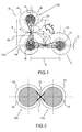
- FIG. 1 presents a diagram illustrating a hinge articulation system with torque of motorization as described in the patent application FR 2968234 supra.
- a motorized torque bearing hinge system comprises substantially parallel winding rolls 1a, 1b and held in position by winding means 3 such as flexible blades, or by any other suitable element, such as for example cables.
- the winding means 3 are wound in the form of eight around the winding rolls 1a, 1b; taken separately, each winding means comprises in particular a linear portion 3a or 3b intersecting at a crossing point C, each linear portion 3a, 3b being extended by a portion of the winding means wrapping around each of the cylinders d winding 1a, 1b.
- the winding means intersect at the crossing point C.
- Flexible tracks 2a, 2b are respectively connected to each of the winding cylinders 1a, 1b with circular section.
- the flexible tracks 2a, 2b are arranged vis-a-vis and in contact with each other.
- An assembly comprising a winding cylinder 1a, 1b and a flexible track 2a, 2b associated forms a fitting 12a, 12b.
- the winding means 3 induce a preload force applying to the point of contact P between the flexible tracks 2a, 2b.
- the point of contact P between the flexible tracks 2a, 2b and the crossover point C of the winding means 3 are aligned on a plane orthogonal to the plane passing through the two axes of revolution of the two winding rolls 1a, 1b.
- Appendices such as solar generators, may be attached to each winding cylinder / flexible lane assembly 1a-2a / 1b-2b.
- the flexible tracks 2a, 2b may consist of flexible tracks in the form of a spiral.
- the profile of the flexible tracks 2a, 2b may also be formed by several portions of spirals, and / or by several portions of circular profile.
- the specific spiral shape makes it possible to off-center the point of contact P between flexible tracks 2a, 2b with respect to the point of intersection C of the winding means 3.
- the point of contact P and the point of intersection C are not found on the same axis parallel to the axes of revolution of the winding rolls 1a, 1b.
- This eccentricity of a distance D, from the point of contact P with respect to the point of intersection C causes the eccentricity of the preload force induced by the winding means 3 and applied to the point of contact P.
- a torque R is produced between the point of contact P and the point of intersection C inducing the rotation of the fittings 12a, 12b comprising the flexible tracks 2a, 2b and the winding rolls 1a, 1b.
- the rotation of the brackets 12a, 12b between them because of the spiral shape of the flexible tracks 2a, 2b, causes a variation of the deformation of the flexible tracks 2a, 2b and more precisely of the arrow at the point of contact, the spacing of the winding rolls 1a, 1b being constant, with a length E in the closed position F equaling a length E 'in the open position O.
- the torque R can be adjusted by means of the choices made on the shape of the spiral and on the physical characteristics of the flexible tracks 2a, 2b, in particular their elasticity and their rigidity.
- To increase the torque R exerted on the flexible tracks 2a, 2b it is possible to increase the offset of the point of contact P with respect to the point of intersection C by making a spiral with a large opening angle, or to increase the force exerted at the point of contact P by making a stiffer flexible track.
- To increase the force exerted at the point of contact C it is still possible to increase the deflection of the flexible tracks 2a, 2b.
- an Archimedean spiral shape may be preferred.
- the drive torque R can also be adapted to compensate for certain variable frictional moments introduced by elements external to the articulation. These can typically be strands of electrical cables carrying electricity between two solar generator panels. It is thus possible to obtain an almost constant motorization margin throughout the deployment. The need for motorization can then be adjusted to the strict minimum
- the present invention can be applied to a rolling articulation system comprising at least two flexible tracks, whatever their shape, and whatever the configuration of the winding means. So the example illustrated by the figure 2 described below comprises flexible tracks of circular shape, arranged around winding rolls, and associated with winding means.
- the figure 2 describes more precisely, in a synoptic manner, a hinge device bearing in the presence of a foreign body.
- the rolling joint device illustrated by the figure 2 comprises two winding rolls 1a, 1b, like the more specific example described above with reference to FIG. figure 1 , as well as flexible tracks 2a, 2b and connecting means 3.
- a foreign body 20 can be housed between the tracks 2a, 2b, the foreign body 20 can then during the movement of the motorization device, be forced to engage more between the flexible tracks 2a, 2b, thus impairing the proper operation the hinge device contributing to an undue torque resistance, or leading to damage to the tracks 2a, 2b, or even a total jamming of the hinge device.
- the present invention makes it possible to reduce such risks, by using flexible tracks and by proposing that the flexible tracks be divided so as to distribute the pre-charge applied to them.
- the present invention proposes that the flexible rolling tracks be formed of a plurality of flexible beam sections over which the preload can be distributed.
- each flexible track may comprise at least one slot, made over all or part of its length, the slot for delimiting several sections of flexible beams.
- the length of a flexible track the dimension according to which the flexible track winds around a winding cylinder.
- the lateral edges of a flexible track can be defined as the edges of the flexible track substantially parallel to the length of the flexible track, that is to say generally registering in a plane perpendicular to the longitudinal axis, or revolution, of the winding cylinder around which is disposed the flexible track considered.
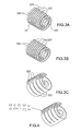
- FIGS. 3A to 3C are perspective views illustrating different configurations of alternative flexible tracks, in a rolling joint system according to various embodiments of the invention.
- a flexible track 32 has a spiral shape, wrapping around a central portion 320 forming a cylinder, or being arranged around a winding cylinder not shown in the figures. This example is not limiting of the present invention.
- the portion of the flexible track 32, in the direction of its length as defined above, located substantially at the central portion 320 may be defined as the proximal portion of the flexible track 32, the flexible track 32 extending on its length up to a part distal 321, terminated by a distal edge substantially perpendicular to the lateral edges of the flexible track 32.
- the flexible track 320 may comprise a plurality of slots 323 made along the length of the flexible track 320, substantially parallel to each other, parallel to the side edges of the flexible track 320, and made along the entire length of the flexible track 320, flexible track 320.
- the slots 323 delimit a plurality of beam sections 325.
- the flexible track 320 may for example, in an alternative embodiment, comprise a plurality of slots 323 'made in the direction of the length of the flexible track 320, substantially parallel to each other, parallel to the lateral edges of the track flexible 320, and made over a portion of the length of the flexible track 320, for example extending from a predetermined distance from the proximal portion of the flexible track 32 away from it along the length of the flexible track 32, flexible track 32, to the distal edge of the flexible track 32.
- the flexible track 320 may for example, in an alternative embodiment, comprise a first plurality of slots 323 'made along the length of the flexible track 320, substantially parallel to each other, parallel to the lateral edges of the flexible track 320, and made over a portion of the length of the flexible track 320, for example extending from a predetermined distance from the proximal portion of the flexible track 32 away from it along the length of the flexible track 32, the flexible track 32, to the distal edge of the flexible track 32, like the slots in the embodiment described above with reference to the figure 3B .
- the flexible track 320 may comprise, like the embodiment described above with reference to FIG.
- a second plurality of slots 323 made along the length of the flexible track 320, substantially parallel to each other, parallel to the lateral edges of the flexible track 320, and made along the entire length of the flexible track 320.
- slots 323 of the second plurality of slots, made over the entire length and the slots 323 'of the first plurality of slots, made over a portion of the length of the flexible track 320, can be alternated.
- the slots are not parallel to the lateral edges of the flexible track.
- the slots may for example form a determined angle with the lateral edges of the flexible track, and thus have a helical shape, promoting the evacuation of foreign bodies.
- the beam sections forming a flexible track may have sections of various shapes.
- the sections of beams may for example be of rectangular section, like the examples illustrated by the FIGS. 3A to 3C . They may also be round or oval section, trapezoidal section, square section, regular or irregular diamond section, square or rectangular sections with rounded corners, diabolo-shaped section, etc.
Abstract
Description
- La présente invention concerne les systèmes de motorisation d'éléments. Elle s'applique notamment au domaine des mécanismes de déploiement d'appendices spatiaux, tels que des antennes ou des générateurs solaires par exemple.
- Dans les systèmes de motorisation précités, des éléments, par exemple des ferrures, sont typiquement mis en mouvement les uns par rapport aux autres autour d'articulations. Ces systèmes comprennent ainsi des lignes d'articulations utilisant généralement des composants de motorisation du type ressorts de torsion, ressorts spiraux ou joints de Carpentier, permettant de lutter contre les couples résistants et de garantir les marges nécessaires en termes de couples générés en vue d'assurer le déploiement complet des appendices.
- Dans ce contexte, les composants de motorisation connus présentent un couple de motorisation évolutif ou variable impliquant une sur-motorisation qui occasionne des chocs en fin de déploiement.
- Ces chocs peuvent être importants et générer des dégâts sur les appendices spatiaux en fin de déploiement, ainsi que des couples parasites néfastes au pilotage de l'engin spatial. Pour pallier ce problème, les structures déployables peuvent être dimensionnées et renforcées de manière à pouvoir résister aux chocs de fin de course générés lors de leur déploiement, mais cette solution n'est pas satisfaisante et entraîne notamment un poids accru pour la structure complète.
- Certains développements ont mené à la mise au point de mécanismes de déploiement à couple résistif quasi-nul. De tels mécanismes, tels que la ligne d'articulations décrite dans la demande de brevet
FR 2635077 FR 0605653 - Les mécanismes connus, tels que ceux décrits dans les demandes de brevets
FR 2635077 FR 0605653 - Pour corriger ces inconvénients, il a été proposé un dispositif de motorisation à couple contrôlé, décrit dans la demande de brevet publiée sous la référence
FR 2968234 - Dans le dispositif précité, un problème peut se poser lorsque des corps étrangers viennent se loger entre les pistes flexibles de roulement, pouvant entraîner jusqu'à un coincement total de l'articulation. Les corps étrangers peuvent provenir de l'espace environnant le dispositif, ou bien du dispositif lui-même, les corps étrangers pouvant alors être des pièces du système accidentellement isolées, ou bien des résidus de matière provenant de phénomènes d'érosion de pièces, par exemple.
- Un but de la présente invention est notamment de pallier les inconvénients précités. Ainsi, il est proposé par la présente invention un dispositif de motorisation comprenant au moins deux pistes flexibles de roulement, ces dernières étant judicieusement configurées de manière à réduire les risques de coincement en cas de présence de corps étrangers, et avantageusement de favoriser l'évacuation de corps étrangers.
- Plus précisément, l'invention a pour objet un dispositif d'articulation à roulement comprenant deux cylindres d'enroulement sensiblement parallèles, des moyens d'enroulement formant élément de liaison de forme longitudinale, les moyens d'enroulement étant aptes à maintenir une distance prédéterminée entre les cylindres d'enroulement et étant enroulés autour des cylindres d'enroulement, et au moins deux pistes flexibles, une piste flexible étant fixée sur chaque cylindre d'enroulement, les pistes flexibles étant disposées en vis-à-vis et présentant un point de contact, un effort de précontrainte s'appliquant audit point de contact des pistes flexibles sous l'effet des moyens d'enroulement, au moins une piste flexible comprenant au moins une fente réalisée sur au moins une partie de sa longueur, ladite fente délimitant une pluralité de sections de poutres flexibles de profils déterminés.
- Dans un mode de réalisation de l'invention, ladite au moins une fente peut être réalisée sur toute la longueur de la piste flexible.
- Dans un mode de réalisation de l'invention, ladite au moins une fente peut être réalisée sur une partie de la longueur de la piste flexible.
- Dans un mode de réalisation de l'invention, une piste flexible peut comprendre une première pluralité de fentes réalisées sur toute la longueur de la piste flexible et une seconde pluralité de fentes réalisées sur une partie de la longueur de la piste flexible.
- Dans un mode de réalisation de l'invention, lesdites sections de poutres peuvent être à section rectangulaire.
- Dans un mode de réalisation de l'invention, lesdites sections de poutres peuvent être à section d'une forme parmi le groupe comprenant les formes ronde, ovale, trapézoïdale, carrée, losange, carrée ou rectangulaire à coins arrondis, forme de diabolo.
- Dans un mode de réalisation de l'invention, les fentes peuvent être sensiblement parallèles aux bords latéraux d'une piste flexible.
- Dans un mode de réalisation de l'invention, les fentes peuvent présenter un angle déterminé avec les bords latéraux d'une piste flexible.
- La présente invention a également pour objet un système déployant pour satellite artificiel, comprenant au moins un premier appendice déployable, un second appendice déployable, et comprenant en outre un dispositif d'articulation à roulement selon l'un quelconque des modes de réalisation présentés, les appendices déployables étant fixés sur chaque ensemble formé par un cylindre d'enroulement et une piste flexible.
- D'autres caractéristiques et avantages de l'invention apparaîtront à l'aide de la description qui suit faite en regard des dessins annexés qui représentent :
- la
figure 1 : un schéma d'un système d'articulation à roulement à couple de motorisation de motorisation connu de l'état de la technique, dans des positions stockée et déployée ; - la
figure 2 , un schéma illustrant de manière synoptique un système d'articulation à roulement en présence d'un corps étranger ; - les
figures 3A, 3B, 3C , des vues en perspectives illustrant différentes configurations de pistes flexibles alternatives, dans un système de motorisation selon différents exemples de réalisation de l'invention ; - la
figure 4 , un schéma illustrant différents profils alternatifs de sections de poutres flexibles, selon différents exemples de réalisation de l'invention. - La
figure 1 présente un schéma illustrant un système d'articulation à roulement à couple de motorisation tel que décrit dans la demande de brevetFR 2968234 - Des pistes flexibles 2a, 2b, sont respectivement connectées à chacun des cylindres d'enroulement 1a, 1b à section circulaire. Les pistes flexibles 2a, 2b sont disposées en vis-à-vis et en contact l'une de l'autre. Un ensemble comprenant un cylindre d'enroulement 1a, 1b et une piste flexible 2a, 2b associée forme une ferrure 12a, 12b. Les moyens d'enroulement 3 induisent un effort de précontrainte s'appliquant au point de contact P entre les pistes flexibles 2a, 2b. Du fait de la géométrie à base circulaire des cylindres d'enroulement 1a, 1b et des pistes flexibles, le point de contact P entre les pistes flexibles 2a, 2b et le point de croisement C des moyens d'enroulement 3 sont alignés sur un plan orthogonal au plan passant par les deux axes de révolution des deux cylindres d'enroulement 1a, 1b. Des appendices, tels que des générateurs solaires, peuvent être fixés sur chaque ensemble cylindre d'enroulement / piste flexible 1a-2a / 1b-2b.
- Les pistes flexibles 2a, 2b peuvent être constituées de pistes flexibles en forme de spirale. Le profil des pistes flexibles 2a, 2b peut également être formé par plusieurs portions de spirales, et/ou par plusieurs portions de profil circulaire. La forme spécifique de spirale permet d'excentrer le point de contact P inter-pistes flexibles 2a, 2b par rapport au point de croisement C des moyens d'enroulement 3. Le point de contact P et le point de croisement C ne se trouvent pas sur le même axe parallèle aux axes de révolution des cylindres d'enroulement 1a, 1b. Cet excentrement d'une distance D, du point de contact P par rapport au point de croisement C, entraîne l'excentrement de l'effort de précontrainte induit par les moyens d'enroulement 3 et s'appliquant au point de contact P. De ce fait, un couple R est produit entre le point de contact P et le point de croisement C induisant la rotation des ferrures 12a, 12b comprenant les pistes flexibles 2a, 2b et les cylindres d'enroulement 1a, 1b. La rotation des ferrures 12a, 12b entre elles, du fait de la forme en spirale des pistes flexibles 2a, 2b, entraîne une variation de la déformation des pistes flexibles 2a, 2b et plus précisément de la flèche au point de contact, l'entraxe des cylindres d'enroulement 1a, 1b, étant quant à lui constant, avec une longueur E en position fermée F égalant une longueur E' en position ouverte O.
- Le couple R peut être ajusté au moyen des choix effectués sur la forme de la spirale et sur les caractéristiques physiques des pistes flexibles 2a, 2b, en particulier leur élasticité et leur rigidité. Pour augmenter le couple R exercé sur les pistes flexibles 2a, 2b, il est possible d'augmenter le déport du point de contact P par rapport au point de croisement C en réalisant une spirale avec un angle d'ouverture important, ou d'augmenter l'effort exercé au point de contact P en réalisant une piste flexible plus raide. Pour augmenter l'effort exercé au point de contact C, il est encore possible d'augmenter la flèche des pistes flexibles 2a, 2b.
- Pour générer un couple R constant pendant la phase de déploiement, une forme de spirale d'Archimède peut être préférée.
- Le couple R de motorisation peut également être adapté afin de compenser certains couples de frottement variables introduits par des éléments externes à l'articulation. Il peut s'agir typiquement des torons de câbles électriques acheminant l'électricité entres deux panneaux de générateur solaire. Il est ainsi possible d'obtenir une marge de motorisation quasi-constante tout au long du déploiement. Le besoin en motorisation peut alors être ajusté au strict nécessaire
- D'une manière plus générale, la présente invention peut s'appliquer à un système d'articulation à roulement comprenant au moins deux pistes flexibles, quelles que soient leurs formes, et quelle que soit par ailleurs la configuration des moyens d'enroulement. Ainsi l'exemple illustré par la
figure 2 décrite ci-après comprend des pistes flexibles de forme circulaire, disposées autour de cylindres d'enroulement, et associées à des moyens d'enroulement. - La
figure 2 décrit plus précisément, de manière synoptique, un dispositif d'articulation à roulement en présence d'un corps étranger. - Le dispositif d'articulation à roulement illustré par la
figure 2 comprend deux cylindres d'enroulement 1a, 1b à l'instar de l'exemple plus spécifique décrit précédemment en référence à lafigure 1 , ainsi que des pistes flexibles 2a, 2b et des moyens de liaison 3. - Un corps étranger 20 peut venir se loger entre les pistes 2a, 2b, le corps étranger 20 pouvant alors lors du mouvement du dispositif de motorisation, être forcé à s'engager plus encore entre les pistes flexibles 2a, 2b, nuisant ainsi au bon fonctionnement du dispositif d'articulation en contribuant à un couple indu de résistance, voire conduisant à un endommagement des pistes 2a, 2b, ou même à un coincement total du dispositif d'articulation.
- La présente invention permet de réduire de tels risques, en utilisant des pistes flexibles et en proposant que les pistes flexibles soient divisées de manière à répartir la pré-charge qui leur est appliquée. A cet effet, la présente invention propose que les pistes flexibles de roulement soient formées d'une pluralité de sections de poutres flexibles sur lesquelles la pré-charge peut être répartie.
- Par exemple, au moins une partie de chaque piste flexible peut comprendre au moins une fente, réalisée sur tout ou partie de sa longueur, la fente permettant de délimiter plusieurs sections de poutres flexibles. Il est entendu ici par la longueur d'une piste flexible, la dimension suivant laquelle la piste flexible s'enroule autour d'un cylindre d'enroulement. Pour la suite, les bords latéraux d'une piste flexible peuvent se définir comme les bords de la piste flexible sensiblement parallèles à la longueur de la piste flexible, c'est-à-dire s'inscrivant globalement dans un plan perpendiculaire à l'axe longitudinal, ou de révolution, du cylindre d'enroulement autour duquel est disposée la piste flexible considérée.
- Les
figures 3A à 3C sont des vues en perspectives illustrant différentes configurations de pistes flexibles alternatives, dans un système d'articulation à roulement selon différents exemples de réalisation de l'invention. Dans les exemples ainsi illustrés, une piste flexible 32 présente une forme de spirale, s'enroulant autour d'une partie centrale 320 formant un cylindre, ou bien étant disposée autour d'un cylindre d'enroulement non représenté sur les figures. Cet exemple n'est pas limitatif de la présente invention. La partie de la piste flexible 32, dans le sens de sa longueur telle que définie précédemment, située sensiblement au niveau de la partie centrale 320 peut être définie comme la partie proximale de la piste flexible 32, la piste flexible 32 s'étendant sur sa longueur jusqu'à une partie distale 321, terminée par un bord distal sensiblement perpendiculaire aux bords latéraux de la piste flexible 32. - En référence à la
figure 3A , la piste flexible 320 peut comprendre une pluralité de fentes 323 réalisées dans le sens de la longueur de la piste flexible 320, sensiblement parallèles les unes aux autres, parallèles aux bords latéraux de la piste flexible 320, et réalisées sur toute la longueur de la piste flexible 320. Les fentes 323 délimitent une pluralité de sections de poutres 325. - En référence à la
figure 3B , la piste flexible 320 peut par exemple, dans un mode de réalisation alternatif, comprendre une pluralité de fentes 323' réalisées dans le sens de la longueur de la piste flexible 320, sensiblement parallèles les unes aux autres, parallèles aux bords latéraux de la piste flexible 320, et réalisées sur une partie de la longueur de la piste flexible 320, par exemple s'étendant depuis une distance déterminée de la partie proximale de la piste flexible 32 en s'éloignant de celle-ci le long de la longueur de la piste flexible 32, jusqu'au bord distal de la piste flexible 32. Les fentes 323' délimitent une pluralité de sections de poutres 325. - En référence à la
figure 3C , la piste flexible 320 peut par exemple, dans un mode de réalisation alternatif, comprendre une première pluralité de fentes 323' réalisées dans le sens de la longueur de la piste flexible 320, sensiblement parallèles les unes aux autres, parallèles aux bords latéraux de la piste flexible 320, et réalisées sur une partie de la longueur de la piste flexible 320, par exemple s'étendant depuis une distance déterminée de la partie proximale de la piste flexible 32 en s'éloignant de celle-ci le long de la longueur de la piste flexible 32, jusqu'au bord distal de la piste flexible 32, à l'instar des fentes dans le mode de réalisation décrit ci-dessus en référence à lafigure 3B . Egalement, la piste flexible 320 peut comprendre, à l'instar du mode de réalisation décrit précédemment en référence à lafigure 3A , une seconde pluralité de fentes 323 réalisées dans le sens de la longueur de la piste flexible 320, sensiblement parallèles les unes aux autres, parallèles aux bords latéraux de la piste flexible 320, et réalisées sur toute la longueur de la piste flexible 320. Les fentes 323 de la seconde pluralité de fentes, réalisées sur toute la longueur et les fentes 323' de la première pluralité de fentes, réalisées sur une partie de la longueur de la piste flexible 320, peuvent être alternées. - Les exemples présentés ci-dessus ne sont aucunement limitatifs de la présente invention, et il peut par exemple être envisagé que les fentes ne soient pas parallèles aux bords latéraux de la piste flexible. Les fentes peuvent par exemple former un angle déterminé avec les bords latéraux de la piste flexible, et ainsi présenter une forme hélicoïdale, favorisant l'évacuation de corps étrangers.
- Avantageusement, ainsi que cela est illustré par la
figure 4 , basée sur un exemple de piste flexible tel que décrit précédemment en référence à lafigure 3C , les sections de poutres formant une piste flexible peuvent présenter des sections de diverses formes. Les sections de poutres peuvent par exemple être à section rectangulaire, à l'instar des exemples illustrés par lesfigures 3A à 3C . Elles peuvent également être à section ronde ou ovale, à section trapézoïdale, à section carrée, à section losange régulier ou non régulier, à sections carrée ou rectangulaire à coins arrondis, à section en forme de diabolo, etc.
Claims (9)
- Dispositif d'articulation à roulement comprenant deux cylindres d'enroulement (1a,1b) sensiblement parallèles, des moyens d'enroulement formant élément de liaison (3) de forme longitudinale, les moyens d'enroulement (3) étant aptes à maintenir une distance prédéterminée entre les cylindres d'enroulement (1a,1b) et étant enroulés autour des cylindres d'enroulement (1a,1b), et au moins deux pistes flexibles (2a,2b), une piste flexible (2a,2b) étant fixée sur chaque cylindre d'enroulement (1a,1b), les pistes flexibles (2a,2b) étant disposées en vis-à-vis et présentant un point de contact (P), un effort de précontrainte s'appliquant audit point de contact (P) des pistes flexibles (2a,2b) sous l'effet des moyens d'enroulement (3), caractérisé en ce qu'au moins une piste flexible (2a, 2b) comprend au moins une fente (323, 323') réalisée sur au moins une partie de sa longueur, ladite fente délimitant une pluralité de sections de poutres (325) flexibles de profils déterminés.
- Dispositif d'articulation à roulement suivant la revendication 1, caractérisé en ce que ladite au moins une fente (323) est réalisée sur toute la longueur de la piste flexible (2a, 2b).
- Dispositif d'articulation à roulement suivant la revendication 1, caractérisé en ce que ladite au moins une fente (323) est réalisée sur une partie de la longueur de la piste flexible (2a, 2b).
- Dispositif d'articulation à roulement suivant la revendication 1, caractérisé en ce qu'une piste flexible (2a, 2b) comprend une première pluralité de fentes (323) réalisées sur toute la longueur de la piste flexible (2a, 2b) et une seconde pluralité de fentes (323') réalisées sur une partie de la longueur de la piste flexible (2a, 2b).
- Dispositif d'articulation à roulement suivant l'une quelconque des revendications précédentes, caractérisé en ce que lesdites sections de poutres (325) sont à section rectangulaire.
- Dispositif d'articulation à roulement suivant l'une quelconque des revendications 1 à 4, caractérisé en ce que lesdites sections de poutres (325) sont à section d'une forme parmi le groupe comprenant les formes ronde, ovale, trapézoïdale, carrée, losange, carrée ou rectangulaire à coins arrondis, forme de diabolo.
- Dispositif d'articulation à roulement suivant l'une quelconque des revendications précédentes, caractérisé en ce que les fentes (323, 323') sont sensiblement parallèles aux bords latéraux d'une piste flexible (2a, 2b).
- Dispositif d'articulation à roulement suivant l'une quelconque des revendications 1 à 6, caractérisé en ce que les fentes (323, 323') présentent un angle déterminé avec les bords latéraux d'une piste flexible (2a, 2b).
- Système déployant pour satellite artificiel, comprenant au moins un premier appendice déployable et un second appendice déployable, caractérisé en ce qu'il comprend en outre un dispositif d'articulation à roulement selon l'une quelconque des revendications précédentes, les appendices déployables étant fixés sur chaque ensemble formé par un cylindre d'enroulement (1a, 1b) et une piste flexible (2a, 2b).
Applications Claiming Priority (1)
| Application Number | Priority Date | Filing Date | Title |
|---|---|---|---|
| FR1202860A FR2997384B1 (fr) | 2012-10-26 | 2012-10-26 | Systeme de motorisation pour articulation a moyens d'enroulement croises a roulement fiabilise |
Publications (3)
| Publication Number | Publication Date |
|---|---|
| EP2724944A2 true EP2724944A2 (fr) | 2014-04-30 |
| EP2724944A3 EP2724944A3 (fr) | 2018-01-03 |
| EP2724944B1 EP2724944B1 (fr) | 2019-04-10 |
Family
ID=47750748
Family Applications (1)
| Application Number | Title | Priority Date | Filing Date |
|---|---|---|---|
| EP13189070.9A Active EP2724944B1 (fr) | 2012-10-26 | 2013-10-17 | Système de motorisation pour articulation à moyens d'enroulement croisés avec roulement fiabilisé |
Country Status (6)
| Country | Link |
|---|---|
| US (1) | US9227739B2 (fr) |
| EP (1) | EP2724944B1 (fr) |
| JP (1) | JP6266301B2 (fr) |
| CN (1) | CN103786898B (fr) |
| ES (1) | ES2733724T3 (fr) |
| FR (1) | FR2997384B1 (fr) |
Cited By (2)
| Publication number | Priority date | Publication date | Assignee | Title |
|---|---|---|---|---|
| US20140117165A1 (en) * | 2012-10-26 | 2014-05-01 | Thales | Motorization system for hinge with flexible rolling tracks |
| CN113263520A (zh) * | 2021-06-24 | 2021-08-17 | 武汉科技大学 | 一种可连续旋转的被动随动液压机器人回转关节 |
Families Citing this family (3)
| Publication number | Priority date | Publication date | Assignee | Title |
|---|---|---|---|---|
| FR2968234B1 (fr) * | 2010-12-07 | 2013-01-04 | Thales Sa | Systeme de motorisation a couple adapte pour structures spatiales deployables |
| FR2997384B1 (fr) * | 2012-10-26 | 2016-09-16 | Thales Sa | Systeme de motorisation pour articulation a moyens d'enroulement croises a roulement fiabilise |
| CN106864772B (zh) * | 2017-01-24 | 2021-06-01 | 航天东方红卫星有限公司 | 航天器预应力薄壁锥形多杆平行并联式空间展开机构 |
Citations (3)
| Publication number | Priority date | Publication date | Assignee | Title |
|---|---|---|---|---|
| FR605653A (fr) | 1924-11-03 | 1926-05-31 | Perfectionnements aux combustibles solides | |
| FR2635077A1 (fr) | 1988-08-08 | 1990-02-09 | Aerospatiale | Articulation auto-motorisee, sans frottement, et ensemble articule tel qu'un panneau solaire de satellite equipe de telles articulations |
| FR2968234A1 (fr) | 2010-12-07 | 2012-06-08 | Thales Sa | Systeme de motorisation a couple adapte pour structures spatiales deployables |
Family Cites Families (11)
| Publication number | Priority date | Publication date | Assignee | Title |
|---|---|---|---|---|
| US3945053A (en) * | 1973-03-05 | 1976-03-23 | Purdue Research Foundation | Rolling contact prosthetic knee joint |
| CA1034393A (fr) * | 1976-10-13 | 1978-07-11 | Henry J. Taylor | Joint articule commande electriquement |
| US4267608A (en) * | 1978-10-04 | 1981-05-19 | Bora Jr F William | Prosthetic joint |
| GB2115478B (en) * | 1982-02-15 | 1985-10-16 | Courier Display Syst | Improvements in and relating to hinges |
| US4558911A (en) * | 1983-12-21 | 1985-12-17 | California Institute Of Technology | Rolling contact robot joint |
| FR2662219B1 (fr) * | 1990-05-17 | 1992-09-04 | Aerospatiale | Dispositif limiteur de couple et appendice deployable d'engin spatial equipe de ce dispositif. |
| JP2001039400A (ja) * | 1999-06-17 | 2001-02-13 | Daimlerchrysler Ag | 人工衛星太陽光発電機用拡開継手 |
| FR2902763B1 (fr) * | 2006-06-23 | 2009-05-22 | Alcatel Sa | Articulation auto-motorisee pour ensemble articule tel qu'un panneau solaire de satellite |
| FR2969524B1 (fr) * | 2010-12-23 | 2013-09-06 | Thales Sa | Articulation auto-motorisee et ensemble articule auto-regules |
| FR2997388B1 (fr) * | 2012-10-26 | 2014-11-28 | Thales Sa | Systeme de motorisation a couple adapte pour articulation a moyens d'enroulement croises |
| FR2997384B1 (fr) * | 2012-10-26 | 2016-09-16 | Thales Sa | Systeme de motorisation pour articulation a moyens d'enroulement croises a roulement fiabilise |
-
2012
- 2012-10-26 FR FR1202860A patent/FR2997384B1/fr not_active Expired - Fee Related
-
2013
- 2013-10-17 ES ES13189070T patent/ES2733724T3/es active Active
- 2013-10-17 EP EP13189070.9A patent/EP2724944B1/fr active Active
- 2013-10-24 US US14/062,644 patent/US9227739B2/en active Active
- 2013-10-25 CN CN201310511583.XA patent/CN103786898B/zh active Active
- 2013-10-25 JP JP2013222576A patent/JP6266301B2/ja active Active
Patent Citations (3)
| Publication number | Priority date | Publication date | Assignee | Title |
|---|---|---|---|---|
| FR605653A (fr) | 1924-11-03 | 1926-05-31 | Perfectionnements aux combustibles solides | |
| FR2635077A1 (fr) | 1988-08-08 | 1990-02-09 | Aerospatiale | Articulation auto-motorisee, sans frottement, et ensemble articule tel qu'un panneau solaire de satellite equipe de telles articulations |
| FR2968234A1 (fr) | 2010-12-07 | 2012-06-08 | Thales Sa | Systeme de motorisation a couple adapte pour structures spatiales deployables |
Cited By (3)
| Publication number | Priority date | Publication date | Assignee | Title |
|---|---|---|---|---|
| US20140117165A1 (en) * | 2012-10-26 | 2014-05-01 | Thales | Motorization system for hinge with flexible rolling tracks |
| CN113263520A (zh) * | 2021-06-24 | 2021-08-17 | 武汉科技大学 | 一种可连续旋转的被动随动液压机器人回转关节 |
| CN113263520B (zh) * | 2021-06-24 | 2023-03-14 | 武汉科技大学 | 一种可连续旋转的被动随动液压机器人回转关节 |
Also Published As
| Publication number | Publication date |
|---|---|
| CN103786898B (zh) | 2017-11-10 |
| EP2724944B1 (fr) | 2019-04-10 |
| CN103786898A (zh) | 2014-05-14 |
| FR2997384B1 (fr) | 2016-09-16 |
| JP2014084114A (ja) | 2014-05-12 |
| JP6266301B2 (ja) | 2018-01-24 |
| FR2997384A1 (fr) | 2014-05-02 |
| EP2724944A3 (fr) | 2018-01-03 |
| US20140116165A1 (en) | 2014-05-01 |
| ES2733724T3 (es) | 2019-12-02 |
| US9227739B2 (en) | 2016-01-05 |
Similar Documents
| Publication | Publication Date | Title |
|---|---|---|
| EP2463200B1 (fr) | Système de motorisation à couple adapté pour structures spatiales déployables | |
| EP2724944B1 (fr) | Système de motorisation pour articulation à moyens d'enroulement croisés avec roulement fiabilisé | |
| EP2032438B1 (fr) | Articulation auto-motorisee pour ensemble articule tel qu'un panneau solaire de satellite | |
| EP2471714B1 (fr) | Générateur solaire plan deroulable | |
| CA2834593C (fr) | Dispositif de deploiement et de reploiement d'une structure flexible, structure deployable flexible et satellite munis d'un tel dispositif | |
| EP2993131B1 (fr) | Mat deployable a deploiement spontane autonome et satellite comportant au moins un tel mat | |
| WO2004039673A1 (fr) | Ensemble articule de panneaux de generateur solaire et vehicule spatial | |
| EP2514674B1 (fr) | Dispositif de protection d'un instrument optique d'un satellite | |
| EP2468630A2 (fr) | Structure deployable formant une antenne equipee d'un generateur solaire pour un satellite | |
| EP0354837A1 (fr) | Articulation auto-motorisée, sans frottement, et ensemble articulé tel qu'un panneau solaire de satellite équipé de telles articulations | |
| EP2724945A2 (fr) | Système de motorisation pour articulation à pistes de roulement flexibles | |
| EP3023333B1 (fr) | Structure déployable escamotable à mètre-ruban | |
| EP3326920A1 (fr) | Structure déployable à déploiement spontané | |
| EP2242683A1 (fr) | Panneau composite monolithique auto-raidi et pivotant, notamment pour une partie mobile d'aeronef | |
| EP2724943B1 (fr) | Système de motorisation à couple adapté pour articulation à moyens d'enroulement croises | |
| EP2468631A1 (fr) | Articulation auto-motorisée et ensemble articulé auto-régulés | |
| CA2982070C (fr) | Faisceau torsible pour pale, un ensemble de faisceaux torsibles, un rotor et un aeronef | |
| FR3095022A1 (fr) | Système de freinage ainsi que procédé et dispositif pour déployer un corps creux de forme allongée enroulé | |
| WO1990003310A1 (fr) | Panneau articule a verrouillage automatique en position deployee, notamment pour generateur solaire de satellite artificiel | |
| EP2461065B1 (fr) | Dispositif d'articulation à faisceau de brins en matériau à mémoire de forme | |
| EP2520494B1 (fr) | Dispositif de protection d'un instrument optique multifaisceaux | |
| WO2017167833A1 (fr) | Dispositif comprenant une charniere flexible et des saillies d'extremite de blocage en cisaillement | |
| FR2833571A1 (fr) | Surface portante aerodynamique ou hydrodynamique | |
| WO2022079187A1 (fr) | Atterrisseur d'aeronef equipe d'un dispositif de verrouillage a ressort a lame | |
| EP0458677B1 (fr) | Dispositif limiteur de couple et appendice déployable d'engin spatial équipé de ce dispositif |
Legal Events
| Date | Code | Title | Description |
|---|---|---|---|
| PUAI | Public reference made under article 153(3) epc to a published international application that has entered the european phase |
Free format text: ORIGINAL CODE: 0009012 |
|
| 17P | Request for examination filed |
Effective date: 20131017 |
|
| AK | Designated contracting states |
Kind code of ref document: A2 Designated state(s): AL AT BE BG CH CY CZ DE DK EE ES FI FR GB GR HR HU IE IS IT LI LT LU LV MC MK MT NL NO PL PT RO RS SE SI SK SM TR |
|
| AX | Request for extension of the european patent |
Extension state: BA ME |
|
| PUAL | Search report despatched |
Free format text: ORIGINAL CODE: 0009013 |
|
| AK | Designated contracting states |
Kind code of ref document: A3 Designated state(s): AL AT BE BG CH CY CZ DE DK EE ES FI FR GB GR HR HU IE IS IT LI LT LU LV MC MK MT NL NO PL PT RO RS SE SI SK SM TR |
|
| AX | Request for extension of the european patent |
Extension state: BA ME |
|
| RIC1 | Information provided on ipc code assigned before grant |
Ipc: E04H 12/18 20060101ALI20171130BHEP Ipc: B25J 17/02 20060101ALN20171130BHEP Ipc: B64G 1/22 20060101AFI20171130BHEP Ipc: E04H 12/08 20060101ALI20171130BHEP Ipc: F16C 11/12 20060101ALI20171130BHEP Ipc: B64G 1/44 20060101ALN20171130BHEP Ipc: E05D 1/02 20060101ALN20171130BHEP |
|
| STAA | Information on the status of an ep patent application or granted ep patent |
Free format text: STATUS: REQUEST FOR EXAMINATION WAS MADE |
|
| 17P | Request for examination filed |
Effective date: 20180703 |
|
| RBV | Designated contracting states (corrected) |
Designated state(s): AL AT BE BG CH CY CZ DE DK EE ES FI FR GB GR HR HU IE IS IT LI LT LU LV MC MK MT NL NO PL PT RO RS SE SI SK SM TR |
|
| RIC1 | Information provided on ipc code assigned before grant |
Ipc: E04H 12/08 20060101ALI20181016BHEP Ipc: F16C 11/12 20060101ALI20181016BHEP Ipc: E04H 12/18 20060101ALI20181016BHEP Ipc: B64G 1/44 20060101ALN20181016BHEP Ipc: E05D 1/02 20060101ALN20181016BHEP Ipc: B25J 17/02 20060101ALN20181016BHEP Ipc: B64G 1/22 20060101AFI20181016BHEP |
|
| GRAP | Despatch of communication of intention to grant a patent |
Free format text: ORIGINAL CODE: EPIDOSNIGR1 |
|
| STAA | Information on the status of an ep patent application or granted ep patent |
Free format text: STATUS: GRANT OF PATENT IS INTENDED |
|
| RIC1 | Information provided on ipc code assigned before grant |
Ipc: B25J 17/02 20060101ALN20181129BHEP Ipc: E04H 12/08 20060101ALI20181129BHEP Ipc: F16C 11/12 20060101ALI20181129BHEP Ipc: E05D 1/02 20060101ALN20181129BHEP Ipc: B64G 1/44 20060101ALN20181129BHEP Ipc: B64G 1/22 20060101AFI20181129BHEP Ipc: E04H 12/18 20060101ALI20181129BHEP |
|
| INTG | Intention to grant announced |
Effective date: 20181217 |
|
| GRAS | Grant fee paid |
Free format text: ORIGINAL CODE: EPIDOSNIGR3 |
|
| GRAA | (expected) grant |
Free format text: ORIGINAL CODE: 0009210 |
|
| STAA | Information on the status of an ep patent application or granted ep patent |
Free format text: STATUS: THE PATENT HAS BEEN GRANTED |
|
| AK | Designated contracting states |
Kind code of ref document: B1 Designated state(s): AL AT BE BG CH CY CZ DE DK EE ES FI FR GB GR HR HU IE IS IT LI LT LU LV MC MK MT NL NO PL PT RO RS SE SI SK SM TR |
|
| RAP1 | Party data changed (applicant data changed or rights of an application transferred) |
Owner name: THALES |
|
| REG | Reference to a national code |
Ref country code: GB Ref legal event code: FG4D Free format text: NOT ENGLISH |
|
| REG | Reference to a national code |
Ref country code: CH Ref legal event code: EP Ref country code: AT Ref legal event code: REF Ref document number: 1118331 Country of ref document: AT Kind code of ref document: T Effective date: 20190415 |
|
| REG | Reference to a national code |
Ref country code: IE Ref legal event code: FG4D Free format text: LANGUAGE OF EP DOCUMENT: FRENCH |
|
| REG | Reference to a national code |
Ref country code: DE Ref legal event code: R096 Ref document number: 602013053588 Country of ref document: DE |
|
| REG | Reference to a national code |
Ref country code: CH Ref legal event code: NV Representative=s name: SERVOPATENT GMBH, CH |
|
| REG | Reference to a national code |
Ref country code: NL Ref legal event code: FP |
|
| REG | Reference to a national code |
Ref country code: LT Ref legal event code: MG4D |
|
| REG | Reference to a national code |
Ref country code: AT Ref legal event code: MK05 Ref document number: 1118331 Country of ref document: AT Kind code of ref document: T Effective date: 20190410 |
|
| PG25 | Lapsed in a contracting state [announced via postgrant information from national office to epo] |
Ref country code: AL Free format text: LAPSE BECAUSE OF FAILURE TO SUBMIT A TRANSLATION OF THE DESCRIPTION OR TO PAY THE FEE WITHIN THE PRESCRIBED TIME-LIMIT Effective date: 20190410 Ref country code: FI Free format text: LAPSE BECAUSE OF FAILURE TO SUBMIT A TRANSLATION OF THE DESCRIPTION OR TO PAY THE FEE WITHIN THE PRESCRIBED TIME-LIMIT Effective date: 20190410 Ref country code: LT Free format text: LAPSE BECAUSE OF FAILURE TO SUBMIT A TRANSLATION OF THE DESCRIPTION OR TO PAY THE FEE WITHIN THE PRESCRIBED TIME-LIMIT Effective date: 20190410 Ref country code: SE Free format text: LAPSE BECAUSE OF FAILURE TO SUBMIT A TRANSLATION OF THE DESCRIPTION OR TO PAY THE FEE WITHIN THE PRESCRIBED TIME-LIMIT Effective date: 20190410 Ref country code: NO Free format text: LAPSE BECAUSE OF FAILURE TO SUBMIT A TRANSLATION OF THE DESCRIPTION OR TO PAY THE FEE WITHIN THE PRESCRIBED TIME-LIMIT Effective date: 20190710 Ref country code: HR Free format text: LAPSE BECAUSE OF FAILURE TO SUBMIT A TRANSLATION OF THE DESCRIPTION OR TO PAY THE FEE WITHIN THE PRESCRIBED TIME-LIMIT Effective date: 20190410 Ref country code: PT Free format text: LAPSE BECAUSE OF FAILURE TO SUBMIT A TRANSLATION OF THE DESCRIPTION OR TO PAY THE FEE WITHIN THE PRESCRIBED TIME-LIMIT Effective date: 20190910 |
|
| PG25 | Lapsed in a contracting state [announced via postgrant information from national office to epo] |
Ref country code: PL Free format text: LAPSE BECAUSE OF FAILURE TO SUBMIT A TRANSLATION OF THE DESCRIPTION OR TO PAY THE FEE WITHIN THE PRESCRIBED TIME-LIMIT Effective date: 20190410 Ref country code: LV Free format text: LAPSE BECAUSE OF FAILURE TO SUBMIT A TRANSLATION OF THE DESCRIPTION OR TO PAY THE FEE WITHIN THE PRESCRIBED TIME-LIMIT Effective date: 20190410 Ref country code: GR Free format text: LAPSE BECAUSE OF FAILURE TO SUBMIT A TRANSLATION OF THE DESCRIPTION OR TO PAY THE FEE WITHIN THE PRESCRIBED TIME-LIMIT Effective date: 20190711 Ref country code: BG Free format text: LAPSE BECAUSE OF FAILURE TO SUBMIT A TRANSLATION OF THE DESCRIPTION OR TO PAY THE FEE WITHIN THE PRESCRIBED TIME-LIMIT Effective date: 20190710 Ref country code: RS Free format text: LAPSE BECAUSE OF FAILURE TO SUBMIT A TRANSLATION OF THE DESCRIPTION OR TO PAY THE FEE WITHIN THE PRESCRIBED TIME-LIMIT Effective date: 20190410 |
|
| REG | Reference to a national code |
Ref country code: ES Ref legal event code: FG2A Ref document number: 2733724 Country of ref document: ES Kind code of ref document: T3 Effective date: 20191202 |
|
| PG25 | Lapsed in a contracting state [announced via postgrant information from national office to epo] |
Ref country code: IS Free format text: LAPSE BECAUSE OF FAILURE TO SUBMIT A TRANSLATION OF THE DESCRIPTION OR TO PAY THE FEE WITHIN THE PRESCRIBED TIME-LIMIT Effective date: 20190810 Ref country code: AT Free format text: LAPSE BECAUSE OF FAILURE TO SUBMIT A TRANSLATION OF THE DESCRIPTION OR TO PAY THE FEE WITHIN THE PRESCRIBED TIME-LIMIT Effective date: 20190410 |
|
| REG | Reference to a national code |
Ref country code: DE Ref legal event code: R097 Ref document number: 602013053588 Country of ref document: DE |
|
| PG25 | Lapsed in a contracting state [announced via postgrant information from national office to epo] |
Ref country code: RO Free format text: LAPSE BECAUSE OF FAILURE TO SUBMIT A TRANSLATION OF THE DESCRIPTION OR TO PAY THE FEE WITHIN THE PRESCRIBED TIME-LIMIT Effective date: 20190410 Ref country code: CZ Free format text: LAPSE BECAUSE OF FAILURE TO SUBMIT A TRANSLATION OF THE DESCRIPTION OR TO PAY THE FEE WITHIN THE PRESCRIBED TIME-LIMIT Effective date: 20190410 Ref country code: SK Free format text: LAPSE BECAUSE OF FAILURE TO SUBMIT A TRANSLATION OF THE DESCRIPTION OR TO PAY THE FEE WITHIN THE PRESCRIBED TIME-LIMIT Effective date: 20190410 Ref country code: EE Free format text: LAPSE BECAUSE OF FAILURE TO SUBMIT A TRANSLATION OF THE DESCRIPTION OR TO PAY THE FEE WITHIN THE PRESCRIBED TIME-LIMIT Effective date: 20190410 Ref country code: DK Free format text: LAPSE BECAUSE OF FAILURE TO SUBMIT A TRANSLATION OF THE DESCRIPTION OR TO PAY THE FEE WITHIN THE PRESCRIBED TIME-LIMIT Effective date: 20190410 |
|
| PLBE | No opposition filed within time limit |
Free format text: ORIGINAL CODE: 0009261 |
|
| STAA | Information on the status of an ep patent application or granted ep patent |
Free format text: STATUS: NO OPPOSITION FILED WITHIN TIME LIMIT |
|
| PG25 | Lapsed in a contracting state [announced via postgrant information from national office to epo] |
Ref country code: SM Free format text: LAPSE BECAUSE OF FAILURE TO SUBMIT A TRANSLATION OF THE DESCRIPTION OR TO PAY THE FEE WITHIN THE PRESCRIBED TIME-LIMIT Effective date: 20190410 |
|
| 26N | No opposition filed |
Effective date: 20200113 |
|
| PG25 | Lapsed in a contracting state [announced via postgrant information from national office to epo] |
Ref country code: TR Free format text: LAPSE BECAUSE OF FAILURE TO SUBMIT A TRANSLATION OF THE DESCRIPTION OR TO PAY THE FEE WITHIN THE PRESCRIBED TIME-LIMIT Effective date: 20190410 |
|
| PG25 | Lapsed in a contracting state [announced via postgrant information from national office to epo] |
Ref country code: MC Free format text: LAPSE BECAUSE OF FAILURE TO SUBMIT A TRANSLATION OF THE DESCRIPTION OR TO PAY THE FEE WITHIN THE PRESCRIBED TIME-LIMIT Effective date: 20190410 Ref country code: SI Free format text: LAPSE BECAUSE OF FAILURE TO SUBMIT A TRANSLATION OF THE DESCRIPTION OR TO PAY THE FEE WITHIN THE PRESCRIBED TIME-LIMIT Effective date: 20190410 |
|
| REG | Reference to a national code |
Ref country code: CH Ref legal event code: PCAR Free format text: NEW ADDRESS: WANNERSTRASSE 9/1, 8045 ZUERICH (CH) |
|
| PG25 | Lapsed in a contracting state [announced via postgrant information from national office to epo] |
Ref country code: LU Free format text: LAPSE BECAUSE OF NON-PAYMENT OF DUE FEES Effective date: 20191017 |
|
| REG | Reference to a national code |
Ref country code: BE Ref legal event code: MM Effective date: 20191031 |
|
| PG25 | Lapsed in a contracting state [announced via postgrant information from national office to epo] |
Ref country code: BE Free format text: LAPSE BECAUSE OF NON-PAYMENT OF DUE FEES Effective date: 20191031 |
|
| PG25 | Lapsed in a contracting state [announced via postgrant information from national office to epo] |
Ref country code: IE Free format text: LAPSE BECAUSE OF NON-PAYMENT OF DUE FEES Effective date: 20191017 |
|
| PG25 | Lapsed in a contracting state [announced via postgrant information from national office to epo] |
Ref country code: CY Free format text: LAPSE BECAUSE OF FAILURE TO SUBMIT A TRANSLATION OF THE DESCRIPTION OR TO PAY THE FEE WITHIN THE PRESCRIBED TIME-LIMIT Effective date: 20190410 |
|
| PG25 | Lapsed in a contracting state [announced via postgrant information from national office to epo] |
Ref country code: MT Free format text: LAPSE BECAUSE OF FAILURE TO SUBMIT A TRANSLATION OF THE DESCRIPTION OR TO PAY THE FEE WITHIN THE PRESCRIBED TIME-LIMIT Effective date: 20190410 Ref country code: HU Free format text: LAPSE BECAUSE OF FAILURE TO SUBMIT A TRANSLATION OF THE DESCRIPTION OR TO PAY THE FEE WITHIN THE PRESCRIBED TIME-LIMIT; INVALID AB INITIO Effective date: 20131017 |
|
| PG25 | Lapsed in a contracting state [announced via postgrant information from national office to epo] |
Ref country code: MK Free format text: LAPSE BECAUSE OF FAILURE TO SUBMIT A TRANSLATION OF THE DESCRIPTION OR TO PAY THE FEE WITHIN THE PRESCRIBED TIME-LIMIT Effective date: 20190410 |
|
| PGFP | Annual fee paid to national office [announced via postgrant information from national office to epo] |
Ref country code: NL Payment date: 20230925 Year of fee payment: 11 Ref country code: GB Payment date: 20230914 Year of fee payment: 11 |
|
| PGFP | Annual fee paid to national office [announced via postgrant information from national office to epo] |
Ref country code: FR Payment date: 20230921 Year of fee payment: 11 |
|
| PGFP | Annual fee paid to national office [announced via postgrant information from national office to epo] |
Ref country code: ES Payment date: 20231108 Year of fee payment: 11 |
|
| PGFP | Annual fee paid to national office [announced via postgrant information from national office to epo] |
Ref country code: IT Payment date: 20230926 Year of fee payment: 11 Ref country code: DE Payment date: 20230919 Year of fee payment: 11 Ref country code: CH Payment date: 20231102 Year of fee payment: 11 |