EP2470868B1 - Système de connexion pour système capteur et système capteur correspondant - Google Patents
Système de connexion pour système capteur et système capteur correspondant Download PDFInfo
- Publication number
- EP2470868B1 EP2470868B1 EP10728675.9A EP10728675A EP2470868B1 EP 2470868 B1 EP2470868 B1 EP 2470868B1 EP 10728675 A EP10728675 A EP 10728675A EP 2470868 B1 EP2470868 B1 EP 2470868B1
- Authority
- EP
- European Patent Office
- Prior art keywords
- connection
- region
- contact
- pieces
- transition
- Prior art date
- Legal status (The legal status is an assumption and is not a legal conclusion. Google has not performed a legal analysis and makes no representation as to the accuracy of the status listed.)
- Active
Links
- 230000007704 transition Effects 0.000 claims description 40
- 238000002347 injection Methods 0.000 claims description 27
- 239000007924 injection Substances 0.000 claims description 27
- 238000000034 method Methods 0.000 claims description 24
- 230000008569 process Effects 0.000 claims description 24
- 238000001746 injection moulding Methods 0.000 claims description 17
- 238000002788 crimping Methods 0.000 claims description 13
- 238000005452 bending Methods 0.000 claims description 7
- 238000007789 sealing Methods 0.000 claims description 7
- 238000005538 encapsulation Methods 0.000 claims description 6
- 239000002991 molded plastic Substances 0.000 claims 2
- 239000004033 plastic Substances 0.000 description 22
- 238000004519 manufacturing process Methods 0.000 description 14
- 238000001125 extrusion Methods 0.000 description 6
- 238000004080 punching Methods 0.000 description 4
- 238000007765 extrusion coating Methods 0.000 description 3
- 239000000463 material Substances 0.000 description 3
- 238000000465 moulding Methods 0.000 description 3
- 238000005476 soldering Methods 0.000 description 3
- 238000003466 welding Methods 0.000 description 3
- 230000002411 adverse Effects 0.000 description 2
- 238000003780 insertion Methods 0.000 description 2
- 230000037431 insertion Effects 0.000 description 2
- 239000004831 Hot glue Substances 0.000 description 1
- 239000004952 Polyamide Substances 0.000 description 1
- 238000004026 adhesive bonding Methods 0.000 description 1
- 230000008901 benefit Effects 0.000 description 1
- 230000001419 dependent effect Effects 0.000 description 1
- 230000010354 integration Effects 0.000 description 1
- 239000013067 intermediate product Substances 0.000 description 1
- 238000005259 measurement Methods 0.000 description 1
- 238000002844 melting Methods 0.000 description 1
- 230000008018 melting Effects 0.000 description 1
- 229920002647 polyamide Polymers 0.000 description 1
- 239000002243 precursor Substances 0.000 description 1
- 239000000047 product Substances 0.000 description 1
- 229910000679 solder Inorganic materials 0.000 description 1
- 239000007921 spray Substances 0.000 description 1
- 238000005507 spraying Methods 0.000 description 1
- 239000012815 thermoplastic material Substances 0.000 description 1
Images


Classifications
-
- G—PHYSICS
- G01—MEASURING; TESTING
- G01D—MEASURING NOT SPECIALLY ADAPTED FOR A SPECIFIC VARIABLE; ARRANGEMENTS FOR MEASURING TWO OR MORE VARIABLES NOT COVERED IN A SINGLE OTHER SUBCLASS; TARIFF METERING APPARATUS; MEASURING OR TESTING NOT OTHERWISE PROVIDED FOR
- G01D11/00—Component parts of measuring arrangements not specially adapted for a specific variable
- G01D11/30—Supports specially adapted for an instrument; Supports specially adapted for a set of instruments
-
- G—PHYSICS
- G01—MEASURING; TESTING
- G01D—MEASURING NOT SPECIALLY ADAPTED FOR A SPECIFIC VARIABLE; ARRANGEMENTS FOR MEASURING TWO OR MORE VARIABLES NOT COVERED IN A SINGLE OTHER SUBCLASS; TARIFF METERING APPARATUS; MEASURING OR TESTING NOT OTHERWISE PROVIDED FOR
- G01D11/00—Component parts of measuring arrangements not specially adapted for a specific variable
- G01D11/24—Housings ; Casings for instruments
- G01D11/245—Housings for sensors
-
- G—PHYSICS
- G01—MEASURING; TESTING
- G01P—MEASURING LINEAR OR ANGULAR SPEED, ACCELERATION, DECELERATION, OR SHOCK; INDICATING PRESENCE, ABSENCE, OR DIRECTION, OF MOVEMENT
- G01P1/00—Details of instruments
- G01P1/02—Housings
- G01P1/026—Housings for speed measuring devices, e.g. pulse generator
Definitions
- the invention relates to a connection arrangement for a sensor arrangement according to the preamble of independent claim 1, and of a corresponding sensor arrangement.
- a magnetic field sensor in particular a rotational speed and / or direction of rotation sensor for a vehicle wheel or for the drive train of a vehicle is described.
- the described magnetic field sensor has a holder for a sensor element and optionally further sensor components.
- the holder is designed as a plastic injection-molded part and has a pocket-like recess in the region of its reading-side end face, in which the sensor element is supported in the final encapsulation with plastic at least in the spray pressure direction and thus protected against mechanical damage.
- connection arrangement for the magnetic field sensor described has a connection element, which has two connection pieces in a first contacting region, which are each electrically and mechanically connected to the stripped ends of a connection cable via a crimp connection. In a second contacting region, the connecting pieces can be electrically and mechanically connected to connection lines of a sensor element.
- the connection element is at least partially enveloped by a plastic encapsulation, which has a window-shaped recess in a transition region between the first contacting region and the second contacting region, which is sealed during the injection process of the plastic encapsulation in the injection molding tool.
- a connecting web present between the crimp connections is generally bent after crimping the individual cores and before the injection process in such a way that the two crimp connections of the individual cores stand closer to one another.
- the greater distance before producing the crimped connections is necessary since the crimping paths are bent out of the material of the connecting element designed as a punching strip.
- the connecting pieces of the magnetic field sensor for the subsequent contacting of the sensor element should be closer together.
- the edges of the bent connecting web between the two crimp connections must be sealed in the injection molding tool by an unfavorable step seal, but this makes it difficult to position, which can lead to increased wear of the tool or over-molding.
- the over-molding in turn can adversely affect subsequent processes, for example, a resistance welding process for contacting the sensor element.
- the publication DE 196 18 631 A1 discloses a device for measuring rotational or angular movements and generating an electrical signal representing the movement.
- the device consists of a transmitter or encoder that rotates with the body whose movement is to be measured, and a stationary transducer.
- This sensor contains in a housing which provided for generating the electrical signal components. Via a connection cable, the signals are led out of the housing.
- the housing consists of two half-shells, which are made of plastic and which are connected after insertion of the electrical components and insertion of the connecting cable by gluing or welding. The interior of the two connected half shells is filled with a hot melt adhesive.
- connection arrangement according to the invention for a sensor arrangement with the features of the independent patent claim 1 has the advantage that in a transition region between a first contacting region and a second contacting region, a positioning opening so is arranged, that the connection element is positionable in the injection molding tool, and the transition region surrounding the positioning opening in the injection molding tool for producing a window-shaped recess in a plastic extrusion is sealed flat.
- a positioning opening so is arranged, that the connection element is positionable in the injection molding tool, and the transition region surrounding the positioning opening in the injection molding tool for producing a window-shaped recess in a plastic extrusion is sealed flat.
- the planar sealing in the transition region can be achieved, for example, by positioning required bending edges of the connection element within the plastic extrusion coating and thus outside the window-shaped recess.
- connection arrangement describes a preliminary product in the production of a sensor arrangement, in particular for measuring rotational speeds and / or rotational directions, which is electrically and mechanically connected to at least one end of a lead of a connection cable via a connection element in the first contacting region and in the second contacting region in a further production step electrically and mechanically connectable to a sensor element.
- the connection element is embodied, for example, as a stamped part and, after the connection with the connection cable, is enveloped at least partially by the plastic extrusion coating during an injection process, which has a window-shaped recess in the transition region, which is sealed during the injection process of the plastic injection molding in the injection molding tool.
- the window-shaped recess is used in the further manufacturing step to electrically and mechanically connect the second contacting region with the sensor element.
- the transition region for bridging an existing height difference which results from the fact that the first contacting region and the second contacting region are arranged in different planes, is designed as an inclined plane, in which two transition webs laterally delimit the positioning opening.
- the execution of the transition region as an inclined plane advantageously allows a surface seal during the injection process, although a height difference between the two contacting areas must be bridged.
- connection arrangement In an embodiment of the connection arrangement according to the invention, two first connecting pieces are arranged in the first contacting region, which are connected to one another via a first connecting web, wherein the first connecting web limits the positioning opening at one end.
- the first Connecting web advantageously allows a one-piece design of the connecting element, whereby the positioning and handling are facilitated during the injection process.
- connection arrangement in a further embodiment of the connection arrangement according to the invention two second connecting pieces are arranged in the second contacting region, which are connected via a second connecting web with each other, wherein the second connecting web limits the positioning opening at the other end.
- a first transition bar connects a first connecting piece with a corresponding second connecting piece
- a second transition bar connects another first connecting piece with a corresponding other second connecting piece.
- connection arrangement in a further embodiment of the connection arrangement according to the invention, the first connecting web and / or the second connecting web are severed after the injection process in order to separate the two first connecting pieces and / or the two second connecting pieces from one another. This results in two electrically isolated from each other signal paths, via which the sensor element can be connected to the connecting cable.
- connection arrangement in the first contacting region the electrical and mechanical connection of the first connection pieces takes place in each case with one end of a core of the connection cable via a crimp connection or a soldering and / or welded connection.
- the crimp connection between the first connecting pieces and one end of a core of the connecting cable can be produced, for example, by first connecting pieces designed as crimping vanes or by additional crimping elements.
- the first connecting pieces designed as crimping vanes are bent after the production of the respective crimping connection, whereby the respective bending area is arranged outside the sealing area for producing the window-shaped recess.
- the arrangement of the bending region outside the sealing area advantageously allows a surface seal in the injection molding tool.
- connection arrangement according to the invention can be used for a sensor arrangement with a sensor element, in particular for measuring the rotational speed and / or the direction of rotation.
- Fig. 1 and 2 each show a schematic, perspective view of a first embodiment of a connecting element 10 for a in 3 and 4 illustrated inventive connection arrangement 1 for a sensor arrangement.
- Fig. 2 shows the connection element 10 after the production of a double crimp connection 11.1, 11.2 with the two-wire connection cable 2.
- the first embodiment of the connection element 10 comprises in a first contacting region 12 two crimping paths designed as first connecting pieces 12.1, 12.2, which are connected via a first connecting web 13 with each other.
- first connecting pieces 12.1, 12.2 which are connected via a first connecting web 13 with each other.
- the two first terminals 12.1, 12.2 in the first contacting area 12 by corresponding crimp 11.1, 11.2 electrically and mechanically connected to a stripped end 3.1, 4.1 a wire 3, 4 of the connecting cable 2.
- the connecting element 10 comprises two second connecting pieces 16.1, 16.2, which are connected via a second connecting web 17 with each other.
- the two second connecting pieces 16.1, 16.2 can be electrically and mechanically connected to a sensor element, not shown, in a further production step.
- a positioning opening 15 is arranged, which is bounded laterally by two transition bars 14.1, 14.2, wherein a first transition bar 14.1 a first connector 12.1 with a second connector 16.1 connects, and a second transition bar 14.2 connects the other first connector 12.2 with the other second connector 16.2.
- first contacting region 12 and the second contacting region 16 of the connecting element 10 are arranged in different planes, wherein the transition region 14 for bridging the existing difference in height is designed as an oblique plane.
- the connecting element 10 is designed for example as a stamped part, which is formed after punching in a desired shape. In this case, after the two crimp connections 12.1, 12.2 have been produced, the first contacting region 12 is bent such that the individual cores 3, 4 of the connection cable 2 are closer together. The greater distance before producing the crimped connection is necessary since the first connecting pieces 12.1, 12.2 designed as crimping paths are bent from the material of the stamped strip.
- the connecting element 10 is bent at the edges of the transition region 14 between the first contacting region 12 and the second contacting region 16 such that an oblique plane for bridging the desired height difference between the two contacting regions 12, 16 is formed.
- the connecting element 10 is at least partially enveloped by a plastic extrusion 20, which has a window-shaped recess 22 in the transition region 14.
- the window-shaped recess 22 is sealed in the injection molding tool during the injection process of the plastic extrusion coating 20 in order to prevent overspray in the area to be kept free of plastic.
- the connection element 10 is positioned in the injection molding tool via the positioning opening 15 in the connection element 10.
- the area surrounding the positioning opening 15, ie, the two connecting webs 13, 17 and the two transitional webs 14.1, 14.2, is sealed to produce the window-shaped recess 22 in the injection molding tool.
- the bends in the first contacting region 12 to achieve the the required distance between the two crimp connections 12.1, 12.2 takes place outside this sealing area, so that the bending areas are arranged within the plastic encapsulation 20.
- the first connecting web 13 and the second connecting web 17 are severed, which in Fig. 4 is shown by a dotted line in order to electrically isolate the two first connecting pieces 12.1, 12.2 and the two second connecting pieces 16.1, 16.2 from each other in order to produce the already mentioned electrically separated signal paths.
- connection arrangement 1 describes a precursor in the production of a sensor arrangement, in particular for the measurement of rotational speeds and / or directions of rotation.
- the connection arrangement 1 connects an unillustrated sensor element electrically to the connection cable 1 3 and 4
- the connection arrangement 1 has a support region 24 for the sensor element, not shown, which can be connected to the connection arrangement 1 in a further production step, for example via a resistance welding process.
- the electrical contacting of the sensor element with the terminal arrangement 1 takes place here via the second connecting pieces 16.1, 16.2.
- the connection with the connection arrangement 1 the resulting sensor arrangement is encapsulated again with plastic.
- the plastic sheath 20 of the connection arrangement 1 for safe integration into the overall envelope melting fins 26.
- the thermoplastic material for both the sheath 20 as well as for the overall envelope of the sensor arrangement, in each case the same polyamide material can be used.
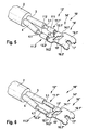
- FIGS. 5 and 6 Two further embodiments of a connecting element 10 ', 10 "described for a connection arrangement according to the invention for a sensor arrangement.
- Fig. 5 shows a schematic, perspective view of a second embodiment of the connection element 10 'for a connection arrangement according to the invention for a sensor arrangement. This shows Fig. 5 the connection element 10 'after the production of a double crimp connection 11.1', 11.2 'with a two-wire connection cable 2.
- FIG. 5 comprises the second embodiment of the connecting element 10 'analogous to the first embodiment in a first contacting region 12', two first connecting pieces 12.1 ', 12.2', which are connected via a first connecting web 13 'with each other.
- the first two connection pieces 12.1 ', 12.2' are in the first contacting region 12 'by corresponding crimp 11.1', 11.2 ', which are produced in contrast to the first embodiment via additional crimping elements 111, 112, electrically and mechanically each with a stripped end 3.1, 4.1 a wire 3, 4 of the connecting cable 2 connected.
- the connecting element 10' comprises, analogously to the first exemplary embodiment, two second connecting pieces 16.1 ', 16.2', which are connected to one another via a second connecting web 17 '.
- the two second connecting pieces 16.1', 16.2 'in a further manufacturing step can be electrically and mechanically connected to a sensor element, not shown.
- a positioning opening 15' is arranged analogously to the first exemplary embodiment, which is bounded laterally by two transition webs 14.1 ', 14.2', wherein a first transition web 14.1 'is a first connecting piece 12.1 'connects to a second connecting piece 16.1', and a second transition bar 14.2 'connects the other first connecting piece 12.2' to the other second connecting piece 16.2 '.
- first connecting web 13 'defining the positioning opening 15' at one end and the second connecting web 17 'defining the positioning opening 15' at the other end over which it does not shown sensor element can be electrically coupled to the connecting cable 2.
- first contacting region 12 'and the second contacting region 16' of the connecting element 10 ' are arranged in different planes, wherein the transitional region 14' for bridging the existing difference in height is designed as an oblique plane.
- the connecting element 10 ' is designed for example as a stamped part, which is formed after punching in a desired shape.
- connection element 10 ' is at least partially enveloped by a plastic extrusion, which has a window-shaped recess in the transition region 14'.
- the connection element 10 'at the edges of the transition region 14' between the first contacting region 12 'and the second contacting region 16' is bent so that an oblique plane for bridging the desired height difference between the two contacting regions 12 ', 16' is formed.
- the window-shaped recess is sealed during the injection process of the plastic extrusion in the injection mold to prevent overspray in the area to be kept free of plastic.
- the connection element 10 ' is positioned in the injection molding tool via the positioning opening 15' in the connection element 10 '.
- the area surrounding the positioning aperture 15 ' i. the two connecting webs 13 ', 17' and the two transitional webs 14.1 ', 14.2', is sealed to produce the window-shaped recess surface in the injection mold.
- the first connecting web 13 'and the second connecting web 17' are severed in order to electrically isolate the two first connecting pieces 12.1 ', 12.2' and the two second connecting pieces 16.1 ', 16.2' from each other by the already mentioned separate signal paths to create.
- Fig. 6 shows a schematic, perspective view of a third embodiment of the connection element 10 "for a connection arrangement according to the invention for a sensor arrangement Fig. 6 the connection element 10 "after the production of a double soldered and / or welded connection 11.1", 11.2 "with a two-wire connection cable 2.
- the third exemplary embodiment of the connecting element 10 “comprises two first connecting pieces 12.1", 12.2 “, which are connected to one another via a first connecting web 13" in a first contacting region 12 ", in contrast to the first and second embodiments Embodiment, the two first terminals 12.1 ", 12.2” in the first contacting area 12 "not by crimp but by soldering and / or welded joints 11.1", 11.2 “electrically and mechanically each with a stripped end 3.1, 4.1 a wire 3, 4 of the connection cable 2 connected.
- the connecting element 10 comprises two second connecting pieces 16.1 “, 16.2", which are connected to one another via a second connecting web 17 "in the second contacting region 16". , 16.2 "in a further manufacturing step are electrically and mechanically connected to a sensor element, not shown.
- a positioning opening 15" is arranged analogously to the first and second embodiments, which is bounded laterally by two transition bars 14.1 “, 14.2", with a first transition bar 14.1 “ first connector 12.1 “with a second connector 16.1” connects, and a second transition bar 14.2 “the other first connector 12.2” with the other second connector 16.2 "connects.
- connection element 10 is at least partially enveloped by a plastic extrusion, which has a window-shaped recess in the transition region 14".
- the connection element 10 is bent at the edges of the transition region 14" between the first contacting region 12 "and the second contacting region 16" in such a way that an oblique plane for bridging the desired height difference between the two contacting regions 12 ", 16" is created.
- the window-shaped recess is sealed during the injection process of the plastic extrusion in the injection mold to prevent overspray in the area to be kept free of plastic.
- connection element 10 is positioned in the injection molding tool via the positioning opening 15" in the connection element 10 "The area surrounding the positioning opening 15", ie the two connection webs 13 “, 17” and the two transition webs 14.1 “, 14.2", is used to produce the window-shaped Recess area sealed in the injection mold.
- the first connecting web 13 "and the second connecting web 17" are severed in order to electrically isolate the two first connecting pieces 12.1 “, 12.2” and the two second connecting pieces 16.1 ", 16.2” from each other by the already mentioned separate signal paths to create.
- Embodiments of the invention allow easy positioning of a connection element in the injection mold and avoid unwanted over-molding during the injection process.
- the production of an intermediate product for producing a sensor arrangement, in particular for measuring rotational speeds and / or rotational directions, is advantageously improved by a positioning opening and by a surface sealing of the area surrounding the positioning opening in the injection molding tool.
Landscapes
- Physics & Mathematics (AREA)
- General Physics & Mathematics (AREA)
- Injection Moulding Of Plastics Or The Like (AREA)
- Connector Housings Or Holding Contact Members (AREA)
- Connections Effected By Soldering, Adhesion, Or Permanent Deformation (AREA)
Claims (10)
- Ensemble de raccordement pour ensemble de capteur, l'ensemble de raccordement présentant un élément de raccordement (10, 10', 10'') raccordé électriquement et mécaniquement dans une première partie de contact (12, 12', 12 ") à une extrémité (3.1, 4.1) d'au moins un fil (3, 4) d'un câble de raccordement (2) et apte à être raccordé électriquement et mécaniquement à un élément de capteur dans une deuxième partie de contact (16, 16', 16"),
l'élément de raccordement (10, 10', 10'') étant englobé au moins en partie par un englobement (20) en matière synthétique qui présente une découpe (22) en forme de fenêtre dans une partie de transition (14, 14', 14'') entre la première partie de contact (12, 12', 12 ") et la deuxième partie de contact (16, 16', 16 ") et qui est fermée hermétiquement dans l'outil de moulage par injection pendant l'opération d'injection de l'englobement (20) en matière synthétique, caractérisé en ce que
une ouverture de positionnement (15, 15', 15'') est disposée dans la partie de transition (14, 14', 14 ") de telle sorte que l'élément de raccordement (10, 10', 10'') puisse être placé dans l'outil de moulage par injection et
en ce que la partie de transition (14, 14', 14'') qui entoure l'ouverture de positionnement (15, 15', 15'') est fermée hermétiquement sur sa surface située dans l'outil de moulage par injection en vue de former la découpe (22) en forme de fenêtre. - Ensemble de raccordement selon la revendication 1, caractérisé en ce que la première partie de contact (12, 12', 12'') et la deuxième partie de contact (16, 16', 16'') sont disposées dans des plans différents, la partie de transition (14, 14', 14'') étant configurée en vue de compenser la différence de hauteur sous la forme d'un plan oblique dans lequel deux nervures de transition (14.1, 14.1', 14.1'', 14.2, 14.2', 14.2'') délimitent latéralement l'ouverture de positionnement (15, 15', 15'').
- Ensemble de raccordement selon les revendications 1 ou 2, caractérisé en ce que dans la première partie de contact (12, 12', 12''), deux premières pièces de contact (12.1, 12.2, 12.1', 12.2', 12.1'', 12.2 ") sont disposées et sont raccordées l'une à l'autre par une première nervure de raccordement (13, 13', 13''), la première nervure de raccordement (13, 13', 13'') délimitant une extrémité de l'ouverture de positionnement (15, 15', 15'').
- Ensemble de raccordement selon les revendications 1 à 3, caractérisé en ce que dans la deuxième partie de contact (16, 16', 16''), deux deuxièmes pièces de raccordement (16.1, 16.2, 16.1', 16.2', 16.1'', 16.2'') sont disposées et sont raccordées l'une à l'autre par une deuxième nervure de raccordement (17, 17', 17''), la deuxième nervure de raccordement (17, 17', 17'') délimitant l'ouverture de positionnement (15, 15', 15'') à l'autre extrémité.
- Ensemble de raccordement selon les revendications 3 ou 4, caractérisé en ce qu'une première nervure de transition (14.1, 14.1', 14.1") relie une première pièce de raccordement (12.1, 12.1', 12.1'') à une deuxième pièce de raccordement (16.1, 16.1', 16.1") correspondante, une deuxième nervure de transition (14.2, 14.2', 14.2'') reliant une autre première pièce de raccordement (12.2, 12.2', 12.2'') à une autre deuxième pièce de raccordement (16.2, 16.2', 16.2'') correspondante.
- Ensemble de raccordement selon l'une des revendications 3 à 5, caractérisé en ce que la première nervure de raccordement (13, 13', 13'') et/ou la deuxième nervure de raccordement (17, 17', 17'') peuvent être séparées après l'opération d'injection pour séparer l'une de l'autre les deux premières pièces de raccordement (12.1, 12.2, 12.1', 12.2', 12.1'', 12.2'') et/ou les deux deuxièmes pièces de raccordement (16.1, 16.2 16.1', 16.2', 16.1", 16.2'').
- Ensemble de raccordement selon l'une des revendications 1 à 6, caractérisé en ce que le raccordement électrique et mécanique de la première pièce de raccordement (12.1, 12.2, 12.1', 12.2', 12.1", 12.2'') à une extrémité (3.1, 4.1) d'un fil (3, 4) du câble de raccordement (2) peut être réalisé dans la première partie de contact (12, 12', 12'') par une liaison sertie (11.1, 11.1', 11.2, 11.2'), une liaison brasée et/ou une liaison soudée (11.1'', 11.2 ").
- Ensemble de raccordement selon la revendication 7, caractérisé en ce que la liaison sertie (11.1, 11.2, 11.1', 11.2') entre les premières pièces de raccordement (12.1, 12.2, 12.1', 12.2') et une extrémité (3.1, 4.1) d'un fil (3, 4) du câble de raccordement (2) peut être réalisée par des premières pièces de raccordement (12.1, 12.2) réalisées sous la forme d'ailettes de sertissage ou par des éléments supplémentaires de sertissage (111, 112).
- Ensemble de raccordement selon la revendication 8, caractérisé en ce que les premières pièces de raccordement (12.1, 12.2) réalisées sous la forme d'ailettes de sertissage peuvent être fléchies après la réalisation de la liaison sertie (11.1, 11.2) correspondante, chaque partie de flexion étant disposée à l'extérieur de la partie d'étanchéité en vue de former la découpe (22) en forme de fenêtre.
- Ensemble de capteur pour véhicule, servant en particulier à déterminer la vitesse de rotation et/ou le sens de rotation et doté d'un élément de capteur caractérisé par un ensemble de raccordement (1) selon l'une des revendications 1 à 9.
Applications Claiming Priority (2)
| Application Number | Priority Date | Filing Date | Title |
|---|---|---|---|
| DE102009028963A DE102009028963A1 (de) | 2009-08-28 | 2009-08-28 | Anschlussanordnung für eine Sensoranordnung und Sensoranordnung |
| PCT/EP2010/059555 WO2011023439A2 (fr) | 2009-08-28 | 2010-07-05 | Système de connexion pour système capteur et système capteur correspondant |
Publications (2)
| Publication Number | Publication Date |
|---|---|
| EP2470868A2 EP2470868A2 (fr) | 2012-07-04 |
| EP2470868B1 true EP2470868B1 (fr) | 2014-12-24 |
Family
ID=43524790
Family Applications (1)
| Application Number | Title | Priority Date | Filing Date |
|---|---|---|---|
| EP10728675.9A Active EP2470868B1 (fr) | 2009-08-28 | 2010-07-05 | Système de connexion pour système capteur et système capteur correspondant |
Country Status (8)
| Country | Link |
|---|---|
| US (1) | US9029702B2 (fr) |
| EP (1) | EP2470868B1 (fr) |
| JP (1) | JP5701298B2 (fr) |
| CN (1) | CN102549392B (fr) |
| BR (1) | BR112012004034B1 (fr) |
| DE (1) | DE102009028963A1 (fr) |
| RU (1) | RU2538353C2 (fr) |
| WO (1) | WO2011023439A2 (fr) |
Families Citing this family (11)
| Publication number | Priority date | Publication date | Assignee | Title |
|---|---|---|---|---|
| JP5541331B2 (ja) | 2012-04-20 | 2014-07-09 | 日立金属株式会社 | 複合ハーネス |
| DE102013226045A1 (de) * | 2013-12-16 | 2015-06-18 | Continental Teves Ag & Co. Ohg | Mechanisch überbestimmt verbauter Drehzahlsensor mit elastischer Umspritzung |
| DE102014202192A1 (de) * | 2014-02-06 | 2015-08-06 | Robert Bosch Gmbh | Sensoreinheit für ein Fahrzeug und Verfahren zur Herstellung einer Sensoreinheit für ein Fahrzeug |
| DE102015205390A1 (de) * | 2015-03-25 | 2016-09-29 | Robert Bosch Gmbh | Sensoranordnung zur Drehzahlerfassung eines rotierenden Bauteils |
| DE102015222582B4 (de) * | 2015-11-16 | 2022-03-31 | Lisa Dräxlmaier GmbH | Vorrichtung zur Abdichtung einer elektrischen Verbindung |
| DE102016210532B4 (de) | 2016-06-14 | 2020-11-26 | Robert Bosch Gmbh | Sensoranordnung |
| DE102016210550B4 (de) | 2016-06-14 | 2020-08-13 | Robert Bosch Gmbh | Sensorvorrichtung und Verfahren zur Herstellung einer Sensorvorrichtung |
| DE102016210519B4 (de) | 2016-06-14 | 2020-09-10 | Robert Bosch Gmbh | Sensoranordnung und Verfahren zur Herstellung einer Sensoranordnung |
| DE102017222681A1 (de) * | 2017-12-13 | 2019-06-13 | Robert Bosch Gmbh | Sensorkopf und Verfahren zur Herstellung eines Sensorkopfes |
| CN208588751U (zh) * | 2018-05-25 | 2019-03-08 | 罗伯特·博世有限公司 | 轮速传感器、用于轮速传感器的传感器头部和车辆 |
| DE102021108660A1 (de) * | 2021-04-07 | 2022-10-13 | Robert Bosch Gesellschaft mit beschränkter Haftung | Sensoreinheit und Verfahren zur Herstellung einer Sensoreinheit |
Family Cites Families (12)
| Publication number | Priority date | Publication date | Assignee | Title |
|---|---|---|---|---|
| US3953058A (en) * | 1974-12-20 | 1976-04-27 | Dale Products, Inc. | Tube coupling |
| SU1530646A1 (ru) * | 1987-05-04 | 1989-12-23 | Центральный научно-исследовательский институт по переработке штапельных волокон | Держатель датчика дл кольцепр дильных машин |
| JPH0720100A (ja) | 1993-07-07 | 1995-01-24 | Toshiba Corp | 超音波液体測定装置 |
| DE19612765A1 (de) * | 1996-03-29 | 1997-11-13 | Teves Gmbh Alfred | Kunststoffsensor und Verfahren zu dessen Herstellung |
| DE19618631A1 (de) * | 1996-05-09 | 1997-11-13 | Teves Gmbh Alfred | Vorrichtung zur Messung von Dreh- oder Winkelbewegungen und ein Verfahren zur Herstellung dieser Vorrichtung |
| DE10111336B4 (de) * | 2001-03-08 | 2008-02-14 | Heraeus Electro-Nite International N.V. | Sensor, insbesondere Temperatur-Sensor, mit einem Messwiderstand |
| WO2002095335A1 (fr) * | 2001-05-23 | 2002-11-28 | Continental Teves Ag & Co. Ohg | Capteur electronique comportant des composants sensibles electroniques et procede de production de ce capteur |
| DE10138482A1 (de) * | 2001-08-04 | 2003-02-13 | Bosch Gmbh Robert | Vorrichtung zumindest bestehend aus zwei Teilen, die miteinander verbunden sind |
| DE10345944B4 (de) * | 2003-10-02 | 2007-06-21 | Robert Bosch Gmbh | Messfühler zur Bestimmung einer physikalischen Eigenschaft eines Gasgemisches |
| DE102005012709A1 (de) * | 2005-03-22 | 2006-09-28 | Robert Bosch Gmbh | Magnetfeldsensor |
| US7735354B2 (en) * | 2006-01-25 | 2010-06-15 | Ngk Spark Plug Co., Ltd. | Liquid-condition detection sensor |
| EP2122784B1 (fr) * | 2007-03-19 | 2014-01-15 | Conti Temic Microelectronic GmbH | Ensemble capteur |
-
2009
- 2009-08-28 DE DE102009028963A patent/DE102009028963A1/de not_active Withdrawn
-
2010
- 2010-07-05 EP EP10728675.9A patent/EP2470868B1/fr active Active
- 2010-07-05 US US13/392,675 patent/US9029702B2/en active Active
- 2010-07-05 WO PCT/EP2010/059555 patent/WO2011023439A2/fr active Application Filing
- 2010-07-05 BR BR112012004034A patent/BR112012004034B1/pt not_active IP Right Cessation
- 2010-07-05 JP JP2012525950A patent/JP5701298B2/ja active Active
- 2010-07-05 CN CN201080037957.3A patent/CN102549392B/zh active Active
- 2010-07-05 RU RU2012111979/28A patent/RU2538353C2/ru not_active IP Right Cessation
Also Published As
| Publication number | Publication date |
|---|---|
| EP2470868A2 (fr) | 2012-07-04 |
| BR112012004034A2 (pt) | 2016-03-29 |
| US20120198933A1 (en) | 2012-08-09 |
| WO2011023439A3 (fr) | 2011-06-16 |
| RU2538353C2 (ru) | 2015-01-10 |
| DE102009028963A1 (de) | 2011-03-03 |
| JP2013503326A (ja) | 2013-01-31 |
| JP5701298B2 (ja) | 2015-04-15 |
| CN102549392A (zh) | 2012-07-04 |
| BR112012004034B1 (pt) | 2019-12-17 |
| RU2012111979A (ru) | 2013-10-10 |
| WO2011023439A2 (fr) | 2011-03-03 |
| US9029702B2 (en) | 2015-05-12 |
| CN102549392B (zh) | 2015-06-03 |
Similar Documents
| Publication | Publication Date | Title |
|---|---|---|
| EP2470868B1 (fr) | Système de connexion pour système capteur et système capteur correspondant | |
| EP1890162B1 (fr) | Dispositif de mesure électrique | |
| EP1699116B1 (fr) | Prise avec membre d'étanchéité pour les contacts sertis et/ou dispositif de retenue de câble | |
| DE202008009002U1 (de) | Magnetfeldsensor | |
| DE202008018152U1 (de) | Sensoradapterschaltungsgehäuseaufbau | |
| EP2520142B1 (fr) | Capteur doté d'un boîtier et procédé de fabrication correspondant | |
| DE102007008074A1 (de) | Modulares Messgerät und Verfahren zu dessen Herstellung | |
| DE102008036399A1 (de) | Datenkabel | |
| DE102011006594A1 (de) | Sensormodul und Verfahren zur Herstellung eines Sensormoduls | |
| DE102014202192A1 (de) | Sensoreinheit für ein Fahrzeug und Verfahren zur Herstellung einer Sensoreinheit für ein Fahrzeug | |
| EP3695469B1 (fr) | Système de ligne électrique à mise en contact directe et procédé de production dudit système | |
| EP2704544B1 (fr) | Dispositif de détection | |
| EP2504677B1 (fr) | Capteur de couple de rotation | |
| DE19722507B4 (de) | Verfahren zur Herstellung einer elektrtrisch leitend mit einer integrierten Schaltung verbundenen Litze integrierte Schaltung mit einem Anschluss und Drehzahlsensor | |
| EP2812664B1 (fr) | Dispositif pour mesurer pression pour un capteur de pression de chambre de combustion | |
| EP3685124B1 (fr) | Support pour une unité de détection | |
| DE112013007708T5 (de) | Modularisierter Geschwindigkeitssensor | |
| DE102021108659A1 (de) | Sensoreinheit und Verfahren zur Herstellung einer Sensoreinheit | |
| EP3102915A1 (fr) | Unité de détection destinée à un véhicule | |
| WO2017215915A9 (fr) | Dispositif de détection et procédé de production d'un dispositif de détection | |
| DE102022202559A1 (de) | Sensoreinheit und Verfahren zur Herstellung einer Sensoreinheit | |
| DE102021108661A1 (de) | Redundante Sensoreinheit und Verfahren zur Herstellung einer Sensoreinheit | |
| DE102006041641B4 (de) | Gehäuse für ein Funktionsmodul sowie Verfahren zur Herstellung des Gehäuses | |
| DE102015225071A1 (de) | Verfahren zur Fertigung eines Raddrehzahlsensors | |
| DE102016210519B4 (de) | Sensoranordnung und Verfahren zur Herstellung einer Sensoranordnung |
Legal Events
| Date | Code | Title | Description |
|---|---|---|---|
| PUAI | Public reference made under article 153(3) epc to a published international application that has entered the european phase |
Free format text: ORIGINAL CODE: 0009012 |
|
| 17P | Request for examination filed |
Effective date: 20120328 |
|
| AK | Designated contracting states |
Kind code of ref document: A2 Designated state(s): AL AT BE BG CH CY CZ DE DK EE ES FI FR GB GR HR HU IE IS IT LI LT LU LV MC MK MT NL NO PL PT RO SE SI SK SM TR |
|
| DAX | Request for extension of the european patent (deleted) | ||
| GRAP | Despatch of communication of intention to grant a patent |
Free format text: ORIGINAL CODE: EPIDOSNIGR1 |
|
| INTG | Intention to grant announced |
Effective date: 20140923 |
|
| GRAS | Grant fee paid |
Free format text: ORIGINAL CODE: EPIDOSNIGR3 |
|
| GRAA | (expected) grant |
Free format text: ORIGINAL CODE: 0009210 |
|
| AK | Designated contracting states |
Kind code of ref document: B1 Designated state(s): AL AT BE BG CH CY CZ DE DK EE ES FI FR GB GR HR HU IE IS IT LI LT LU LV MC MK MT NL NO PL PT RO SE SI SK SM TR |
|
| REG | Reference to a national code |
Ref country code: GB Ref legal event code: FG4D Free format text: NOT ENGLISH |
|
| REG | Reference to a national code |
Ref country code: CH Ref legal event code: EP |
|
| REG | Reference to a national code |
Ref country code: IE Ref legal event code: FG4D Free format text: LANGUAGE OF EP DOCUMENT: GERMAN |
|
| REG | Reference to a national code |
Ref country code: AT Ref legal event code: REF Ref document number: 703387 Country of ref document: AT Kind code of ref document: T Effective date: 20150115 |
|
| REG | Reference to a national code |
Ref country code: DE Ref legal event code: R096 Ref document number: 502010008577 Country of ref document: DE Effective date: 20150219 |
|
| REG | Reference to a national code |
Ref country code: NL Ref legal event code: VDEP Effective date: 20141224 |
|
| PG25 | Lapsed in a contracting state [announced via postgrant information from national office to epo] |
Ref country code: LT Free format text: LAPSE BECAUSE OF FAILURE TO SUBMIT A TRANSLATION OF THE DESCRIPTION OR TO PAY THE FEE WITHIN THE PRESCRIBED TIME-LIMIT Effective date: 20141224 Ref country code: NO Free format text: LAPSE BECAUSE OF FAILURE TO SUBMIT A TRANSLATION OF THE DESCRIPTION OR TO PAY THE FEE WITHIN THE PRESCRIBED TIME-LIMIT Effective date: 20150324 Ref country code: FI Free format text: LAPSE BECAUSE OF FAILURE TO SUBMIT A TRANSLATION OF THE DESCRIPTION OR TO PAY THE FEE WITHIN THE PRESCRIBED TIME-LIMIT Effective date: 20141224 |
|
| REG | Reference to a national code |
Ref country code: LT Ref legal event code: MG4D |
|
| PG25 | Lapsed in a contracting state [announced via postgrant information from national office to epo] |
Ref country code: SE Free format text: LAPSE BECAUSE OF FAILURE TO SUBMIT A TRANSLATION OF THE DESCRIPTION OR TO PAY THE FEE WITHIN THE PRESCRIBED TIME-LIMIT Effective date: 20141224 Ref country code: LV Free format text: LAPSE BECAUSE OF FAILURE TO SUBMIT A TRANSLATION OF THE DESCRIPTION OR TO PAY THE FEE WITHIN THE PRESCRIBED TIME-LIMIT Effective date: 20141224 Ref country code: GR Free format text: LAPSE BECAUSE OF FAILURE TO SUBMIT A TRANSLATION OF THE DESCRIPTION OR TO PAY THE FEE WITHIN THE PRESCRIBED TIME-LIMIT Effective date: 20150325 Ref country code: HR Free format text: LAPSE BECAUSE OF FAILURE TO SUBMIT A TRANSLATION OF THE DESCRIPTION OR TO PAY THE FEE WITHIN THE PRESCRIBED TIME-LIMIT Effective date: 20141224 |
|
| PG25 | Lapsed in a contracting state [announced via postgrant information from national office to epo] |
Ref country code: NL Free format text: LAPSE BECAUSE OF FAILURE TO SUBMIT A TRANSLATION OF THE DESCRIPTION OR TO PAY THE FEE WITHIN THE PRESCRIBED TIME-LIMIT Effective date: 20141224 |
|
| PG25 | Lapsed in a contracting state [announced via postgrant information from national office to epo] |
Ref country code: CZ Free format text: LAPSE BECAUSE OF FAILURE TO SUBMIT A TRANSLATION OF THE DESCRIPTION OR TO PAY THE FEE WITHIN THE PRESCRIBED TIME-LIMIT Effective date: 20141224 Ref country code: RO Free format text: LAPSE BECAUSE OF FAILURE TO SUBMIT A TRANSLATION OF THE DESCRIPTION OR TO PAY THE FEE WITHIN THE PRESCRIBED TIME-LIMIT Effective date: 20141224 Ref country code: SK Free format text: LAPSE BECAUSE OF FAILURE TO SUBMIT A TRANSLATION OF THE DESCRIPTION OR TO PAY THE FEE WITHIN THE PRESCRIBED TIME-LIMIT Effective date: 20141224 Ref country code: ES Free format text: LAPSE BECAUSE OF FAILURE TO SUBMIT A TRANSLATION OF THE DESCRIPTION OR TO PAY THE FEE WITHIN THE PRESCRIBED TIME-LIMIT Effective date: 20141224 Ref country code: EE Free format text: LAPSE BECAUSE OF FAILURE TO SUBMIT A TRANSLATION OF THE DESCRIPTION OR TO PAY THE FEE WITHIN THE PRESCRIBED TIME-LIMIT Effective date: 20141224 |
|
| PG25 | Lapsed in a contracting state [announced via postgrant information from national office to epo] |
Ref country code: PL Free format text: LAPSE BECAUSE OF FAILURE TO SUBMIT A TRANSLATION OF THE DESCRIPTION OR TO PAY THE FEE WITHIN THE PRESCRIBED TIME-LIMIT Effective date: 20141224 Ref country code: IS Free format text: LAPSE BECAUSE OF FAILURE TO SUBMIT A TRANSLATION OF THE DESCRIPTION OR TO PAY THE FEE WITHIN THE PRESCRIBED TIME-LIMIT Effective date: 20150424 |
|
| REG | Reference to a national code |
Ref country code: DE Ref legal event code: R097 Ref document number: 502010008577 Country of ref document: DE |
|
| PG25 | Lapsed in a contracting state [announced via postgrant information from national office to epo] |
Ref country code: DK Free format text: LAPSE BECAUSE OF FAILURE TO SUBMIT A TRANSLATION OF THE DESCRIPTION OR TO PAY THE FEE WITHIN THE PRESCRIBED TIME-LIMIT Effective date: 20141224 |
|
| PLBE | No opposition filed within time limit |
Free format text: ORIGINAL CODE: 0009261 |
|
| STAA | Information on the status of an ep patent application or granted ep patent |
Free format text: STATUS: NO OPPOSITION FILED WITHIN TIME LIMIT |
|
| 26N | No opposition filed |
Effective date: 20150925 |
|
| PG25 | Lapsed in a contracting state [announced via postgrant information from national office to epo] |
Ref country code: IT Free format text: LAPSE BECAUSE OF FAILURE TO SUBMIT A TRANSLATION OF THE DESCRIPTION OR TO PAY THE FEE WITHIN THE PRESCRIBED TIME-LIMIT Effective date: 20141224 |
|
| PG25 | Lapsed in a contracting state [announced via postgrant information from national office to epo] |
Ref country code: SI Free format text: LAPSE BECAUSE OF FAILURE TO SUBMIT A TRANSLATION OF THE DESCRIPTION OR TO PAY THE FEE WITHIN THE PRESCRIBED TIME-LIMIT Effective date: 20141224 Ref country code: MC Free format text: LAPSE BECAUSE OF FAILURE TO SUBMIT A TRANSLATION OF THE DESCRIPTION OR TO PAY THE FEE WITHIN THE PRESCRIBED TIME-LIMIT Effective date: 20141224 |
|
| REG | Reference to a national code |
Ref country code: CH Ref legal event code: PL |
|
| GBPC | Gb: european patent ceased through non-payment of renewal fee |
Effective date: 20150705 |
|
| PG25 | Lapsed in a contracting state [announced via postgrant information from national office to epo] |
Ref country code: LU Free format text: LAPSE BECAUSE OF FAILURE TO SUBMIT A TRANSLATION OF THE DESCRIPTION OR TO PAY THE FEE WITHIN THE PRESCRIBED TIME-LIMIT Effective date: 20150705 |
|
| REG | Reference to a national code |
Ref country code: IE Ref legal event code: MM4A |
|
| PG25 | Lapsed in a contracting state [announced via postgrant information from national office to epo] |
Ref country code: GB Free format text: LAPSE BECAUSE OF NON-PAYMENT OF DUE FEES Effective date: 20150705 Ref country code: CH Free format text: LAPSE BECAUSE OF NON-PAYMENT OF DUE FEES Effective date: 20150731 Ref country code: LI Free format text: LAPSE BECAUSE OF NON-PAYMENT OF DUE FEES Effective date: 20150731 |
|
| REG | Reference to a national code |
Ref country code: FR Ref legal event code: ST Effective date: 20160331 |
|
| PG25 | Lapsed in a contracting state [announced via postgrant information from national office to epo] |
Ref country code: FR Free format text: LAPSE BECAUSE OF NON-PAYMENT OF DUE FEES Effective date: 20150731 |
|
| PG25 | Lapsed in a contracting state [announced via postgrant information from national office to epo] |
Ref country code: IE Free format text: LAPSE BECAUSE OF NON-PAYMENT OF DUE FEES Effective date: 20150705 |
|
| REG | Reference to a national code |
Ref country code: AT Ref legal event code: MM01 Ref document number: 703387 Country of ref document: AT Kind code of ref document: T Effective date: 20150705 |
|
| PG25 | Lapsed in a contracting state [announced via postgrant information from national office to epo] |
Ref country code: AT Free format text: LAPSE BECAUSE OF NON-PAYMENT OF DUE FEES Effective date: 20150705 |
|
| PG25 | Lapsed in a contracting state [announced via postgrant information from national office to epo] |
Ref country code: MT Free format text: LAPSE BECAUSE OF FAILURE TO SUBMIT A TRANSLATION OF THE DESCRIPTION OR TO PAY THE FEE WITHIN THE PRESCRIBED TIME-LIMIT Effective date: 20141224 |
|
| PG25 | Lapsed in a contracting state [announced via postgrant information from national office to epo] |
Ref country code: BG Free format text: LAPSE BECAUSE OF FAILURE TO SUBMIT A TRANSLATION OF THE DESCRIPTION OR TO PAY THE FEE WITHIN THE PRESCRIBED TIME-LIMIT Effective date: 20141224 Ref country code: SM Free format text: LAPSE BECAUSE OF FAILURE TO SUBMIT A TRANSLATION OF THE DESCRIPTION OR TO PAY THE FEE WITHIN THE PRESCRIBED TIME-LIMIT Effective date: 20141224 Ref country code: HU Free format text: LAPSE BECAUSE OF FAILURE TO SUBMIT A TRANSLATION OF THE DESCRIPTION OR TO PAY THE FEE WITHIN THE PRESCRIBED TIME-LIMIT; INVALID AB INITIO Effective date: 20100705 |
|
| PG25 | Lapsed in a contracting state [announced via postgrant information from national office to epo] |
Ref country code: CY Free format text: LAPSE BECAUSE OF FAILURE TO SUBMIT A TRANSLATION OF THE DESCRIPTION OR TO PAY THE FEE WITHIN THE PRESCRIBED TIME-LIMIT Effective date: 20141224 |
|
| PG25 | Lapsed in a contracting state [announced via postgrant information from national office to epo] |
Ref country code: BE Free format text: LAPSE BECAUSE OF NON-PAYMENT OF DUE FEES Effective date: 20150731 |
|
| PG25 | Lapsed in a contracting state [announced via postgrant information from national office to epo] |
Ref country code: TR Free format text: LAPSE BECAUSE OF FAILURE TO SUBMIT A TRANSLATION OF THE DESCRIPTION OR TO PAY THE FEE WITHIN THE PRESCRIBED TIME-LIMIT Effective date: 20141224 |
|
| PG25 | Lapsed in a contracting state [announced via postgrant information from national office to epo] |
Ref country code: MK Free format text: LAPSE BECAUSE OF FAILURE TO SUBMIT A TRANSLATION OF THE DESCRIPTION OR TO PAY THE FEE WITHIN THE PRESCRIBED TIME-LIMIT Effective date: 20141224 |
|
| PG25 | Lapsed in a contracting state [announced via postgrant information from national office to epo] |
Ref country code: PT Free format text: LAPSE BECAUSE OF FAILURE TO SUBMIT A TRANSLATION OF THE DESCRIPTION OR TO PAY THE FEE WITHIN THE PRESCRIBED TIME-LIMIT Effective date: 20141224 |
|
| PG25 | Lapsed in a contracting state [announced via postgrant information from national office to epo] |
Ref country code: AL Free format text: LAPSE BECAUSE OF FAILURE TO SUBMIT A TRANSLATION OF THE DESCRIPTION OR TO PAY THE FEE WITHIN THE PRESCRIBED TIME-LIMIT Effective date: 20141224 |
|
| PGFP | Annual fee paid to national office [announced via postgrant information from national office to epo] |
Ref country code: DE Payment date: 20230922 Year of fee payment: 14 |