EP2470390B1 - Kraftfahrzeug - Google Patents
Kraftfahrzeug Download PDFInfo
- Publication number
- EP2470390B1 EP2470390B1 EP10747188.0A EP10747188A EP2470390B1 EP 2470390 B1 EP2470390 B1 EP 2470390B1 EP 10747188 A EP10747188 A EP 10747188A EP 2470390 B1 EP2470390 B1 EP 2470390B1
- Authority
- EP
- European Patent Office
- Prior art keywords
- module
- vehicle
- central
- vehicle according
- motor vehicle
- Prior art date
- Legal status (The legal status is an assumption and is not a legal conclusion. Google has not performed a legal analysis and makes no representation as to the accuracy of the status listed.)
- Not-in-force
Links
Images

Classifications
-
- B—PERFORMING OPERATIONS; TRANSPORTING
- B62—LAND VEHICLES FOR TRAVELLING OTHERWISE THAN ON RAILS
- B62D—MOTOR VEHICLES; TRAILERS
- B62D21/00—Understructures, i.e. chassis frame on which a vehicle body may be mounted
- B62D21/02—Understructures, i.e. chassis frame on which a vehicle body may be mounted comprising longitudinally or transversely arranged frame members
- B62D21/04—Understructures, i.e. chassis frame on which a vehicle body may be mounted comprising longitudinally or transversely arranged frame members single longitudinal type
-
- B—PERFORMING OPERATIONS; TRANSPORTING
- B60—VEHICLES IN GENERAL
- B60K—ARRANGEMENT OR MOUNTING OF PROPULSION UNITS OR OF TRANSMISSIONS IN VEHICLES; ARRANGEMENT OR MOUNTING OF PLURAL DIVERSE PRIME-MOVERS IN VEHICLES; AUXILIARY DRIVES FOR VEHICLES; INSTRUMENTATION OR DASHBOARDS FOR VEHICLES; ARRANGEMENTS IN CONNECTION WITH COOLING, AIR INTAKE, GAS EXHAUST OR FUEL SUPPLY OF PROPULSION UNITS IN VEHICLES
- B60K1/00—Arrangement or mounting of electrical propulsion units
-
- B—PERFORMING OPERATIONS; TRANSPORTING
- B60—VEHICLES IN GENERAL
- B60K—ARRANGEMENT OR MOUNTING OF PROPULSION UNITS OR OF TRANSMISSIONS IN VEHICLES; ARRANGEMENT OR MOUNTING OF PLURAL DIVERSE PRIME-MOVERS IN VEHICLES; AUXILIARY DRIVES FOR VEHICLES; INSTRUMENTATION OR DASHBOARDS FOR VEHICLES; ARRANGEMENTS IN CONNECTION WITH COOLING, AIR INTAKE, GAS EXHAUST OR FUEL SUPPLY OF PROPULSION UNITS IN VEHICLES
- B60K1/00—Arrangement or mounting of electrical propulsion units
- B60K1/04—Arrangement or mounting of electrical propulsion units of the electric storage means for propulsion
-
- B—PERFORMING OPERATIONS; TRANSPORTING
- B60—VEHICLES IN GENERAL
- B60K—ARRANGEMENT OR MOUNTING OF PROPULSION UNITS OR OF TRANSMISSIONS IN VEHICLES; ARRANGEMENT OR MOUNTING OF PLURAL DIVERSE PRIME-MOVERS IN VEHICLES; AUXILIARY DRIVES FOR VEHICLES; INSTRUMENTATION OR DASHBOARDS FOR VEHICLES; ARRANGEMENTS IN CONNECTION WITH COOLING, AIR INTAKE, GAS EXHAUST OR FUEL SUPPLY OF PROPULSION UNITS IN VEHICLES
- B60K11/00—Arrangement in connection with cooling of propulsion units
- B60K11/02—Arrangement in connection with cooling of propulsion units with liquid cooling
- B60K11/04—Arrangement or mounting of radiators, radiator shutters, or radiator blinds
-
- B—PERFORMING OPERATIONS; TRANSPORTING
- B60—VEHICLES IN GENERAL
- B60K—ARRANGEMENT OR MOUNTING OF PROPULSION UNITS OR OF TRANSMISSIONS IN VEHICLES; ARRANGEMENT OR MOUNTING OF PLURAL DIVERSE PRIME-MOVERS IN VEHICLES; AUXILIARY DRIVES FOR VEHICLES; INSTRUMENTATION OR DASHBOARDS FOR VEHICLES; ARRANGEMENTS IN CONNECTION WITH COOLING, AIR INTAKE, GAS EXHAUST OR FUEL SUPPLY OF PROPULSION UNITS IN VEHICLES
- B60K15/00—Arrangement in connection with fuel supply of combustion engines or other fuel consuming energy converters, e.g. fuel cells; Mounting or construction of fuel tanks
- B60K15/03—Fuel tanks
- B60K15/063—Arrangement of tanks
-
- B—PERFORMING OPERATIONS; TRANSPORTING
- B60—VEHICLES IN GENERAL
- B60K—ARRANGEMENT OR MOUNTING OF PROPULSION UNITS OR OF TRANSMISSIONS IN VEHICLES; ARRANGEMENT OR MOUNTING OF PLURAL DIVERSE PRIME-MOVERS IN VEHICLES; AUXILIARY DRIVES FOR VEHICLES; INSTRUMENTATION OR DASHBOARDS FOR VEHICLES; ARRANGEMENTS IN CONNECTION WITH COOLING, AIR INTAKE, GAS EXHAUST OR FUEL SUPPLY OF PROPULSION UNITS IN VEHICLES
- B60K5/00—Arrangement or mounting of internal-combustion or jet-propulsion units
-
- B—PERFORMING OPERATIONS; TRANSPORTING
- B60—VEHICLES IN GENERAL
- B60K—ARRANGEMENT OR MOUNTING OF PROPULSION UNITS OR OF TRANSMISSIONS IN VEHICLES; ARRANGEMENT OR MOUNTING OF PLURAL DIVERSE PRIME-MOVERS IN VEHICLES; AUXILIARY DRIVES FOR VEHICLES; INSTRUMENTATION OR DASHBOARDS FOR VEHICLES; ARRANGEMENTS IN CONNECTION WITH COOLING, AIR INTAKE, GAS EXHAUST OR FUEL SUPPLY OF PROPULSION UNITS IN VEHICLES
- B60K5/00—Arrangement or mounting of internal-combustion or jet-propulsion units
- B60K5/04—Arrangement or mounting of internal-combustion or jet-propulsion units with the engine main axis, e.g. crankshaft axis, transversely to the longitudinal centre line of the vehicle
-
- B—PERFORMING OPERATIONS; TRANSPORTING
- B60—VEHICLES IN GENERAL
- B60K—ARRANGEMENT OR MOUNTING OF PROPULSION UNITS OR OF TRANSMISSIONS IN VEHICLES; ARRANGEMENT OR MOUNTING OF PLURAL DIVERSE PRIME-MOVERS IN VEHICLES; AUXILIARY DRIVES FOR VEHICLES; INSTRUMENTATION OR DASHBOARDS FOR VEHICLES; ARRANGEMENTS IN CONNECTION WITH COOLING, AIR INTAKE, GAS EXHAUST OR FUEL SUPPLY OF PROPULSION UNITS IN VEHICLES
- B60K6/00—Arrangement or mounting of plural diverse prime-movers for mutual or common propulsion, e.g. hybrid propulsion systems comprising electric motors and internal combustion engines
- B60K6/20—Arrangement or mounting of plural diverse prime-movers for mutual or common propulsion, e.g. hybrid propulsion systems comprising electric motors and internal combustion engines the prime-movers consisting of electric motors and internal combustion engines, e.g. HEVs
- B60K6/50—Architecture of the driveline characterised by arrangement or kind of transmission units
- B60K6/52—Driving a plurality of drive axles, e.g. four-wheel drive
-
- B—PERFORMING OPERATIONS; TRANSPORTING
- B60—VEHICLES IN GENERAL
- B60L—PROPULSION OF ELECTRICALLY-PROPELLED VEHICLES; SUPPLYING ELECTRIC POWER FOR AUXILIARY EQUIPMENT OF ELECTRICALLY-PROPELLED VEHICLES; ELECTRODYNAMIC BRAKE SYSTEMS FOR VEHICLES IN GENERAL; MAGNETIC SUSPENSION OR LEVITATION FOR VEHICLES; MONITORING OPERATING VARIABLES OF ELECTRICALLY-PROPELLED VEHICLES; ELECTRIC SAFETY DEVICES FOR ELECTRICALLY-PROPELLED VEHICLES
- B60L1/00—Supplying electric power to auxiliary equipment of vehicles
- B60L1/003—Supplying electric power to auxiliary equipment of vehicles to auxiliary motors, e.g. for pumps, compressors
-
- B—PERFORMING OPERATIONS; TRANSPORTING
- B60—VEHICLES IN GENERAL
- B60L—PROPULSION OF ELECTRICALLY-PROPELLED VEHICLES; SUPPLYING ELECTRIC POWER FOR AUXILIARY EQUIPMENT OF ELECTRICALLY-PROPELLED VEHICLES; ELECTRODYNAMIC BRAKE SYSTEMS FOR VEHICLES IN GENERAL; MAGNETIC SUSPENSION OR LEVITATION FOR VEHICLES; MONITORING OPERATING VARIABLES OF ELECTRICALLY-PROPELLED VEHICLES; ELECTRIC SAFETY DEVICES FOR ELECTRICALLY-PROPELLED VEHICLES
- B60L15/00—Methods, circuits, or devices for controlling the traction-motor speed of electrically-propelled vehicles
- B60L15/20—Methods, circuits, or devices for controlling the traction-motor speed of electrically-propelled vehicles for control of the vehicle or its driving motor to achieve a desired performance, e.g. speed, torque, programmed variation of speed
-
- B—PERFORMING OPERATIONS; TRANSPORTING
- B60—VEHICLES IN GENERAL
- B60L—PROPULSION OF ELECTRICALLY-PROPELLED VEHICLES; SUPPLYING ELECTRIC POWER FOR AUXILIARY EQUIPMENT OF ELECTRICALLY-PROPELLED VEHICLES; ELECTRODYNAMIC BRAKE SYSTEMS FOR VEHICLES IN GENERAL; MAGNETIC SUSPENSION OR LEVITATION FOR VEHICLES; MONITORING OPERATING VARIABLES OF ELECTRICALLY-PROPELLED VEHICLES; ELECTRIC SAFETY DEVICES FOR ELECTRICALLY-PROPELLED VEHICLES
- B60L3/00—Electric devices on electrically-propelled vehicles for safety purposes; Monitoring operating variables, e.g. speed, deceleration or energy consumption
- B60L3/0023—Detecting, eliminating, remedying or compensating for drive train abnormalities, e.g. failures within the drive train
- B60L3/0061—Detecting, eliminating, remedying or compensating for drive train abnormalities, e.g. failures within the drive train relating to electrical machines
-
- B—PERFORMING OPERATIONS; TRANSPORTING
- B60—VEHICLES IN GENERAL
- B60L—PROPULSION OF ELECTRICALLY-PROPELLED VEHICLES; SUPPLYING ELECTRIC POWER FOR AUXILIARY EQUIPMENT OF ELECTRICALLY-PROPELLED VEHICLES; ELECTRODYNAMIC BRAKE SYSTEMS FOR VEHICLES IN GENERAL; MAGNETIC SUSPENSION OR LEVITATION FOR VEHICLES; MONITORING OPERATING VARIABLES OF ELECTRICALLY-PROPELLED VEHICLES; ELECTRIC SAFETY DEVICES FOR ELECTRICALLY-PROPELLED VEHICLES
- B60L50/00—Electric propulsion with power supplied within the vehicle
- B60L50/10—Electric propulsion with power supplied within the vehicle using propulsion power supplied by engine-driven generators, e.g. generators driven by combustion engines
- B60L50/16—Electric propulsion with power supplied within the vehicle using propulsion power supplied by engine-driven generators, e.g. generators driven by combustion engines with provision for separate direct mechanical propulsion
-
- B—PERFORMING OPERATIONS; TRANSPORTING
- B60—VEHICLES IN GENERAL
- B60L—PROPULSION OF ELECTRICALLY-PROPELLED VEHICLES; SUPPLYING ELECTRIC POWER FOR AUXILIARY EQUIPMENT OF ELECTRICALLY-PROPELLED VEHICLES; ELECTRODYNAMIC BRAKE SYSTEMS FOR VEHICLES IN GENERAL; MAGNETIC SUSPENSION OR LEVITATION FOR VEHICLES; MONITORING OPERATING VARIABLES OF ELECTRICALLY-PROPELLED VEHICLES; ELECTRIC SAFETY DEVICES FOR ELECTRICALLY-PROPELLED VEHICLES
- B60L50/00—Electric propulsion with power supplied within the vehicle
- B60L50/50—Electric propulsion with power supplied within the vehicle using propulsion power supplied by batteries or fuel cells
- B60L50/60—Electric propulsion with power supplied within the vehicle using propulsion power supplied by batteries or fuel cells using power supplied by batteries
- B60L50/61—Electric propulsion with power supplied within the vehicle using propulsion power supplied by batteries or fuel cells using power supplied by batteries by batteries charged by engine-driven generators, e.g. series hybrid electric vehicles
-
- B—PERFORMING OPERATIONS; TRANSPORTING
- B60—VEHICLES IN GENERAL
- B60L—PROPULSION OF ELECTRICALLY-PROPELLED VEHICLES; SUPPLYING ELECTRIC POWER FOR AUXILIARY EQUIPMENT OF ELECTRICALLY-PROPELLED VEHICLES; ELECTRODYNAMIC BRAKE SYSTEMS FOR VEHICLES IN GENERAL; MAGNETIC SUSPENSION OR LEVITATION FOR VEHICLES; MONITORING OPERATING VARIABLES OF ELECTRICALLY-PROPELLED VEHICLES; ELECTRIC SAFETY DEVICES FOR ELECTRICALLY-PROPELLED VEHICLES
- B60L50/00—Electric propulsion with power supplied within the vehicle
- B60L50/50—Electric propulsion with power supplied within the vehicle using propulsion power supplied by batteries or fuel cells
- B60L50/60—Electric propulsion with power supplied within the vehicle using propulsion power supplied by batteries or fuel cells using power supplied by batteries
- B60L50/66—Arrangements of batteries
-
- B—PERFORMING OPERATIONS; TRANSPORTING
- B60—VEHICLES IN GENERAL
- B60L—PROPULSION OF ELECTRICALLY-PROPELLED VEHICLES; SUPPLYING ELECTRIC POWER FOR AUXILIARY EQUIPMENT OF ELECTRICALLY-PROPELLED VEHICLES; ELECTRODYNAMIC BRAKE SYSTEMS FOR VEHICLES IN GENERAL; MAGNETIC SUSPENSION OR LEVITATION FOR VEHICLES; MONITORING OPERATING VARIABLES OF ELECTRICALLY-PROPELLED VEHICLES; ELECTRIC SAFETY DEVICES FOR ELECTRICALLY-PROPELLED VEHICLES
- B60L58/00—Methods or circuit arrangements for monitoring or controlling batteries or fuel cells, specially adapted for electric vehicles
- B60L58/10—Methods or circuit arrangements for monitoring or controlling batteries or fuel cells, specially adapted for electric vehicles for monitoring or controlling batteries
- B60L58/24—Methods or circuit arrangements for monitoring or controlling batteries or fuel cells, specially adapted for electric vehicles for monitoring or controlling batteries for controlling the temperature of batteries
- B60L58/26—Methods or circuit arrangements for monitoring or controlling batteries or fuel cells, specially adapted for electric vehicles for monitoring or controlling batteries for controlling the temperature of batteries by cooling
-
- B—PERFORMING OPERATIONS; TRANSPORTING
- B60—VEHICLES IN GENERAL
- B60L—PROPULSION OF ELECTRICALLY-PROPELLED VEHICLES; SUPPLYING ELECTRIC POWER FOR AUXILIARY EQUIPMENT OF ELECTRICALLY-PROPELLED VEHICLES; ELECTRODYNAMIC BRAKE SYSTEMS FOR VEHICLES IN GENERAL; MAGNETIC SUSPENSION OR LEVITATION FOR VEHICLES; MONITORING OPERATING VARIABLES OF ELECTRICALLY-PROPELLED VEHICLES; ELECTRIC SAFETY DEVICES FOR ELECTRICALLY-PROPELLED VEHICLES
- B60L7/00—Electrodynamic brake systems for vehicles in general
- B60L7/10—Dynamic electric regenerative braking
- B60L7/14—Dynamic electric regenerative braking for vehicles propelled by AC motors
-
- B—PERFORMING OPERATIONS; TRANSPORTING
- B62—LAND VEHICLES FOR TRAVELLING OTHERWISE THAN ON RAILS
- B62D—MOTOR VEHICLES; TRAILERS
- B62D21/00—Understructures, i.e. chassis frame on which a vehicle body may be mounted
- B62D21/17—Understructures, i.e. chassis frame on which a vehicle body may be mounted forming fluid or electrical conduit means or having other means to accommodate the transmission of a force or signal
-
- B—PERFORMING OPERATIONS; TRANSPORTING
- B62—LAND VEHICLES FOR TRAVELLING OTHERWISE THAN ON RAILS
- B62D—MOTOR VEHICLES; TRAILERS
- B62D25/00—Superstructure or monocoque structure sub-units; Parts or details thereof not otherwise provided for
- B62D25/08—Front or rear portions
-
- B—PERFORMING OPERATIONS; TRANSPORTING
- B62—LAND VEHICLES FOR TRAVELLING OTHERWISE THAN ON RAILS
- B62D—MOTOR VEHICLES; TRAILERS
- B62D25/00—Superstructure or monocoque structure sub-units; Parts or details thereof not otherwise provided for
- B62D25/20—Floors or bottom sub-units
- B62D25/2009—Floors or bottom sub-units in connection with other superstructure subunits
-
- B—PERFORMING OPERATIONS; TRANSPORTING
- B62—LAND VEHICLES FOR TRAVELLING OTHERWISE THAN ON RAILS
- B62D—MOTOR VEHICLES; TRAILERS
- B62D63/00—Motor vehicles or trailers not otherwise provided for
- B62D63/02—Motor vehicles
- B62D63/025—Modular vehicles
-
- B—PERFORMING OPERATIONS; TRANSPORTING
- B62—LAND VEHICLES FOR TRAVELLING OTHERWISE THAN ON RAILS
- B62D—MOTOR VEHICLES; TRAILERS
- B62D65/00—Designing, manufacturing, e.g. assembling, facilitating disassembly, or structurally modifying motor vehicles or trailers, not otherwise provided for
- B62D65/02—Joining sub-units or components to, or positioning sub-units or components with respect to, body shell or other sub-units or components
- B62D65/04—Joining preassembled modular units composed of sub-units performing diverse functions, e.g. engine and bonnet
-
- B—PERFORMING OPERATIONS; TRANSPORTING
- B60—VEHICLES IN GENERAL
- B60K—ARRANGEMENT OR MOUNTING OF PROPULSION UNITS OR OF TRANSMISSIONS IN VEHICLES; ARRANGEMENT OR MOUNTING OF PLURAL DIVERSE PRIME-MOVERS IN VEHICLES; AUXILIARY DRIVES FOR VEHICLES; INSTRUMENTATION OR DASHBOARDS FOR VEHICLES; ARRANGEMENTS IN CONNECTION WITH COOLING, AIR INTAKE, GAS EXHAUST OR FUEL SUPPLY OF PROPULSION UNITS IN VEHICLES
- B60K1/00—Arrangement or mounting of electrical propulsion units
- B60K2001/003—Arrangement or mounting of electrical propulsion units with means for cooling the electrical propulsion units
- B60K2001/005—Arrangement or mounting of electrical propulsion units with means for cooling the electrical propulsion units the electric storage means
-
- B—PERFORMING OPERATIONS; TRANSPORTING
- B60—VEHICLES IN GENERAL
- B60K—ARRANGEMENT OR MOUNTING OF PROPULSION UNITS OR OF TRANSMISSIONS IN VEHICLES; ARRANGEMENT OR MOUNTING OF PLURAL DIVERSE PRIME-MOVERS IN VEHICLES; AUXILIARY DRIVES FOR VEHICLES; INSTRUMENTATION OR DASHBOARDS FOR VEHICLES; ARRANGEMENTS IN CONNECTION WITH COOLING, AIR INTAKE, GAS EXHAUST OR FUEL SUPPLY OF PROPULSION UNITS IN VEHICLES
- B60K1/00—Arrangement or mounting of electrical propulsion units
- B60K1/04—Arrangement or mounting of electrical propulsion units of the electric storage means for propulsion
- B60K2001/0405—Arrangement or mounting of electrical propulsion units of the electric storage means for propulsion characterised by their position
- B60K2001/0427—Arrangement between the seats
-
- B—PERFORMING OPERATIONS; TRANSPORTING
- B60—VEHICLES IN GENERAL
- B60L—PROPULSION OF ELECTRICALLY-PROPELLED VEHICLES; SUPPLYING ELECTRIC POWER FOR AUXILIARY EQUIPMENT OF ELECTRICALLY-PROPELLED VEHICLES; ELECTRODYNAMIC BRAKE SYSTEMS FOR VEHICLES IN GENERAL; MAGNETIC SUSPENSION OR LEVITATION FOR VEHICLES; MONITORING OPERATING VARIABLES OF ELECTRICALLY-PROPELLED VEHICLES; ELECTRIC SAFETY DEVICES FOR ELECTRICALLY-PROPELLED VEHICLES
- B60L2210/00—Converter types
- B60L2210/10—DC to DC converters
-
- B—PERFORMING OPERATIONS; TRANSPORTING
- B60—VEHICLES IN GENERAL
- B60L—PROPULSION OF ELECTRICALLY-PROPELLED VEHICLES; SUPPLYING ELECTRIC POWER FOR AUXILIARY EQUIPMENT OF ELECTRICALLY-PROPELLED VEHICLES; ELECTRODYNAMIC BRAKE SYSTEMS FOR VEHICLES IN GENERAL; MAGNETIC SUSPENSION OR LEVITATION FOR VEHICLES; MONITORING OPERATING VARIABLES OF ELECTRICALLY-PROPELLED VEHICLES; ELECTRIC SAFETY DEVICES FOR ELECTRICALLY-PROPELLED VEHICLES
- B60L2210/00—Converter types
- B60L2210/40—DC to AC converters
-
- B—PERFORMING OPERATIONS; TRANSPORTING
- B60—VEHICLES IN GENERAL
- B60L—PROPULSION OF ELECTRICALLY-PROPELLED VEHICLES; SUPPLYING ELECTRIC POWER FOR AUXILIARY EQUIPMENT OF ELECTRICALLY-PROPELLED VEHICLES; ELECTRODYNAMIC BRAKE SYSTEMS FOR VEHICLES IN GENERAL; MAGNETIC SUSPENSION OR LEVITATION FOR VEHICLES; MONITORING OPERATING VARIABLES OF ELECTRICALLY-PROPELLED VEHICLES; ELECTRIC SAFETY DEVICES FOR ELECTRICALLY-PROPELLED VEHICLES
- B60L2220/00—Electrical machine types; Structures or applications thereof
- B60L2220/10—Electrical machine types
- B60L2220/14—Synchronous machines
-
- B—PERFORMING OPERATIONS; TRANSPORTING
- B60—VEHICLES IN GENERAL
- B60L—PROPULSION OF ELECTRICALLY-PROPELLED VEHICLES; SUPPLYING ELECTRIC POWER FOR AUXILIARY EQUIPMENT OF ELECTRICALLY-PROPELLED VEHICLES; ELECTRODYNAMIC BRAKE SYSTEMS FOR VEHICLES IN GENERAL; MAGNETIC SUSPENSION OR LEVITATION FOR VEHICLES; MONITORING OPERATING VARIABLES OF ELECTRICALLY-PROPELLED VEHICLES; ELECTRIC SAFETY DEVICES FOR ELECTRICALLY-PROPELLED VEHICLES
- B60L2240/00—Control parameters of input or output; Target parameters
- B60L2240/10—Vehicle control parameters
- B60L2240/34—Cabin temperature
-
- B—PERFORMING OPERATIONS; TRANSPORTING
- B60—VEHICLES IN GENERAL
- B60L—PROPULSION OF ELECTRICALLY-PROPELLED VEHICLES; SUPPLYING ELECTRIC POWER FOR AUXILIARY EQUIPMENT OF ELECTRICALLY-PROPELLED VEHICLES; ELECTRODYNAMIC BRAKE SYSTEMS FOR VEHICLES IN GENERAL; MAGNETIC SUSPENSION OR LEVITATION FOR VEHICLES; MONITORING OPERATING VARIABLES OF ELECTRICALLY-PROPELLED VEHICLES; ELECTRIC SAFETY DEVICES FOR ELECTRICALLY-PROPELLED VEHICLES
- B60L2240/00—Control parameters of input or output; Target parameters
- B60L2240/40—Drive Train control parameters
- B60L2240/42—Drive Train control parameters related to electric machines
- B60L2240/423—Torque
-
- B—PERFORMING OPERATIONS; TRANSPORTING
- B60—VEHICLES IN GENERAL
- B60L—PROPULSION OF ELECTRICALLY-PROPELLED VEHICLES; SUPPLYING ELECTRIC POWER FOR AUXILIARY EQUIPMENT OF ELECTRICALLY-PROPELLED VEHICLES; ELECTRODYNAMIC BRAKE SYSTEMS FOR VEHICLES IN GENERAL; MAGNETIC SUSPENSION OR LEVITATION FOR VEHICLES; MONITORING OPERATING VARIABLES OF ELECTRICALLY-PROPELLED VEHICLES; ELECTRIC SAFETY DEVICES FOR ELECTRICALLY-PROPELLED VEHICLES
- B60L2240/00—Control parameters of input or output; Target parameters
- B60L2240/40—Drive Train control parameters
- B60L2240/44—Drive Train control parameters related to combustion engines
- B60L2240/443—Torque
-
- B—PERFORMING OPERATIONS; TRANSPORTING
- B60—VEHICLES IN GENERAL
- B60L—PROPULSION OF ELECTRICALLY-PROPELLED VEHICLES; SUPPLYING ELECTRIC POWER FOR AUXILIARY EQUIPMENT OF ELECTRICALLY-PROPELLED VEHICLES; ELECTRODYNAMIC BRAKE SYSTEMS FOR VEHICLES IN GENERAL; MAGNETIC SUSPENSION OR LEVITATION FOR VEHICLES; MONITORING OPERATING VARIABLES OF ELECTRICALLY-PROPELLED VEHICLES; ELECTRIC SAFETY DEVICES FOR ELECTRICALLY-PROPELLED VEHICLES
- B60L2260/00—Operating Modes
- B60L2260/20—Drive modes; Transition between modes
- B60L2260/28—Four wheel or all wheel drive
-
- B—PERFORMING OPERATIONS; TRANSPORTING
- B60—VEHICLES IN GENERAL
- B60Y—INDEXING SCHEME RELATING TO ASPECTS CROSS-CUTTING VEHICLE TECHNOLOGY
- B60Y2400/00—Special features of vehicle units
- B60Y2400/61—Arrangements of controllers for electric machines, e.g. inverters
-
- Y—GENERAL TAGGING OF NEW TECHNOLOGICAL DEVELOPMENTS; GENERAL TAGGING OF CROSS-SECTIONAL TECHNOLOGIES SPANNING OVER SEVERAL SECTIONS OF THE IPC; TECHNICAL SUBJECTS COVERED BY FORMER USPC CROSS-REFERENCE ART COLLECTIONS [XRACs] AND DIGESTS
- Y02—TECHNOLOGIES OR APPLICATIONS FOR MITIGATION OR ADAPTATION AGAINST CLIMATE CHANGE
- Y02T—CLIMATE CHANGE MITIGATION TECHNOLOGIES RELATED TO TRANSPORTATION
- Y02T10/00—Road transport of goods or passengers
- Y02T10/60—Other road transportation technologies with climate change mitigation effect
- Y02T10/62—Hybrid vehicles
-
- Y—GENERAL TAGGING OF NEW TECHNOLOGICAL DEVELOPMENTS; GENERAL TAGGING OF CROSS-SECTIONAL TECHNOLOGIES SPANNING OVER SEVERAL SECTIONS OF THE IPC; TECHNICAL SUBJECTS COVERED BY FORMER USPC CROSS-REFERENCE ART COLLECTIONS [XRACs] AND DIGESTS
- Y02—TECHNOLOGIES OR APPLICATIONS FOR MITIGATION OR ADAPTATION AGAINST CLIMATE CHANGE
- Y02T—CLIMATE CHANGE MITIGATION TECHNOLOGIES RELATED TO TRANSPORTATION
- Y02T10/00—Road transport of goods or passengers
- Y02T10/60—Other road transportation technologies with climate change mitigation effect
- Y02T10/64—Electric machine technologies in electromobility
-
- Y—GENERAL TAGGING OF NEW TECHNOLOGICAL DEVELOPMENTS; GENERAL TAGGING OF CROSS-SECTIONAL TECHNOLOGIES SPANNING OVER SEVERAL SECTIONS OF THE IPC; TECHNICAL SUBJECTS COVERED BY FORMER USPC CROSS-REFERENCE ART COLLECTIONS [XRACs] AND DIGESTS
- Y02—TECHNOLOGIES OR APPLICATIONS FOR MITIGATION OR ADAPTATION AGAINST CLIMATE CHANGE
- Y02T—CLIMATE CHANGE MITIGATION TECHNOLOGIES RELATED TO TRANSPORTATION
- Y02T10/00—Road transport of goods or passengers
- Y02T10/60—Other road transportation technologies with climate change mitigation effect
- Y02T10/70—Energy storage systems for electromobility, e.g. batteries
-
- Y—GENERAL TAGGING OF NEW TECHNOLOGICAL DEVELOPMENTS; GENERAL TAGGING OF CROSS-SECTIONAL TECHNOLOGIES SPANNING OVER SEVERAL SECTIONS OF THE IPC; TECHNICAL SUBJECTS COVERED BY FORMER USPC CROSS-REFERENCE ART COLLECTIONS [XRACs] AND DIGESTS
- Y02—TECHNOLOGIES OR APPLICATIONS FOR MITIGATION OR ADAPTATION AGAINST CLIMATE CHANGE
- Y02T—CLIMATE CHANGE MITIGATION TECHNOLOGIES RELATED TO TRANSPORTATION
- Y02T10/00—Road transport of goods or passengers
- Y02T10/60—Other road transportation technologies with climate change mitigation effect
- Y02T10/7072—Electromobility specific charging systems or methods for batteries, ultracapacitors, supercapacitors or double-layer capacitors
-
- Y—GENERAL TAGGING OF NEW TECHNOLOGICAL DEVELOPMENTS; GENERAL TAGGING OF CROSS-SECTIONAL TECHNOLOGIES SPANNING OVER SEVERAL SECTIONS OF THE IPC; TECHNICAL SUBJECTS COVERED BY FORMER USPC CROSS-REFERENCE ART COLLECTIONS [XRACs] AND DIGESTS
- Y02—TECHNOLOGIES OR APPLICATIONS FOR MITIGATION OR ADAPTATION AGAINST CLIMATE CHANGE
- Y02T—CLIMATE CHANGE MITIGATION TECHNOLOGIES RELATED TO TRANSPORTATION
- Y02T10/00—Road transport of goods or passengers
- Y02T10/60—Other road transportation technologies with climate change mitigation effect
- Y02T10/72—Electric energy management in electromobility
Definitions
- the invention relates to a motor vehicle with a chassis frame.
- motor vehicles are for example from the EP 0 868 338 B1 , of the EP 0 653 344 B1 , of the WO 01/64501 A1 and the AT 208 243 B known.
- the vehicle body can be made separately from the chassis frame and connected in a simple manner in the subsequent assembly process with the chassis frame.
- a motor vehicle with a chassis frame which has a front module and a rear module, which are interconnected via a central module.
- the central module receives at least one memory from which a drive unit of the motor vehicle is supplied with energy.
- Both the front module and the rear module each carry at least one drive unit.
- the object of the invention is to develop the known motor vehicle.
- the motor vehicle according to the invention is based on an extremely variable vehicle architecture with which a wide range of different types of motor vehicles can be realized, including various drive concepts for these motor vehicles.
- the range within an underlying vehicle architecture includes, for example, sports cars, limousine, hatchback and combination type vehicles, motor vehicles, which are designed in the urban area primarily for transport and short-distance operation and also vehicles with greater ground clearance.
- the design of the chassis frame also plays an important role.
- the different types of motor vehicles and drive concepts can be presented on the basis of a modular chassis frame, which consists of the three modules front module, central module and rear module, with little effort. Primarily, the width of the front and rear modules as well as the width and length of the central module are changed.
- a group of different types of vehicles possibly with different drive concepts, are generated, with low design and manufacturing expense and thus with low production costs.
- the width adaptation of the two modules can be effected in a simple manner by cutting the extruded profiles to length or by corresponding folding and trimming of the sheet metal components.
- the support structure of front module and rear module has in an advantageous embodiment of the invention as essential components comparatively large-area cast components, which carry the elements of the front and rear axles and can also accommodate a number of other components and units, such as drive units and their peripherals, gears, Heat exchanger etc. Furthermore, connections for a front or rear bumper are provided.
- the cast components are mainly provided in the lateral area of the front and / or rear module.
- the luggage compartment can be formed either on the chassis frame or on the vehicle body. Due to the width variation of front and rear module, the track and / or the width of the motor vehicle can be changed.
- the central module preferably has a closed cross-section to a bending and torsionally rigid connection of front module and rear module guarantee. Changes in the length of the central module affect the wheelbase and / or the length of the motor vehicle.
- connection between the front module or rear module on the one hand and the central module on the other hand is preferably carried out by a screw and / or adhesive connection.
- a welded joint is conceivable.
- the type of joining technology used depends inter alia on the material used in the vehicle concept in question.
- the connection module consists for example of an extruded profile, a cast node, etc.
- Chassis frame and vehicle body are preferably connected to each other at a few defined locations, for example by a screw connection.
- a surface connection between the chassis frame and vehicle body is possible, for example by gluing, optionally with additional screw, or by welding.
- the motor vehicle is configured with an electric motor on the front axle and a combination of internal combustion engine and electric motor on the rear axle.
- an internal combustion engine at the rear axle short lines to the fuel tank and the mufflers of the exhaust system arise.
- the front module is provided for the arrangement of one or more heat exchangers, for example for a heating and / or air conditioning unit for the vehicle interior, a cooling circuit for at least one drive unit and / or power electronics and / or for another electrical unit and / or for an electric battery.
- heat exchangers for example for a heating and / or air conditioning unit for the vehicle interior
- cooling circuit for at least one drive unit and / or power electronics and / or for another electrical unit and / or for an electric battery.
- powerful batteries such as lithium-polymer batteries, must be sufficiently cooled.
- driver unit is to be understood in the context of the present invention, any type of aggregate that serves the drive of the motor vehicle, such as internal combustion engines, electric motors, gas turbines, etc.
- the combustion engines can be used for different fossil, biological and synthetic hydrocarbon fuels be designed for hydrogen fuel.
- the central module has the task of storing an operating medium to supply the at least one drive unit.
- the central module can be designed for this purpose in a very variable manner and record, for example, a relatively small tank for gasoline or diesel fuel, a larger tank for natural gas or a very bulky tank for hydrogen. Even electric batteries can be arranged in smaller or larger numbers in the central module. For this purpose, the width and / or the length and / or the height of the central module can be varied.
- Drive units may be designed in unit with a transmission, such as an electric motor in a transmission housing as part of a so-called hybrid drive, which is supplemented by an internal combustion engine. Due to the presence of electric motors, the motor vehicle can be driven electrically and thus operated without emissions by an internal combustion engine. Additionally or alternatively, at least one electric motor can be used to support an internal combustion engine.
- a transmission such as an electric motor in a transmission housing as part of a so-called hybrid drive, which is supplemented by an internal combustion engine. Due to the presence of electric motors, the motor vehicle can be driven electrically and thus operated without emissions by an internal combustion engine. Additionally or alternatively, at least one electric motor can be used to support an internal combustion engine.
- the motor vehicle according to the invention with the electric motors energy can be recovered in coasting phases and / or when braking the motor vehicle by at least one electric motor is connected as a generator.
- the recuperation when using the electric motor for service braking supplies particularly high charging currents in the electric battery and reduces wear the components of the friction brake of the motor vehicle.
- the use of the electric motor as a service brake has an advantageous effect, in particular in motor vehicles according to the invention with an electric motor on the front axle, since during braking as a result of the dynamic axle load change, the front axle is loaded more heavily and thus a higher recuperation power can be achieved.
- a recuperation can be done on both vehicle axles in a particularly effective manner.
- the central module Due to the manifold possibilities of arranging a memory for a working medium for supplying at least one drive unit in the central module, in contrast to conventional motor vehicles, no installation space is lost at the expense of the occupants or the luggage compartment.
- the operating medium in the motor vehicle according to the invention in an advantageous manner be housed in the central module.
- the central module is ideally able to accommodate electric batteries with a large capacity, which in turn claim considerable space in the interior and / or in the luggage compartment in known vehicles.
- the batteries are designed, for example, as lithium polymer accumulators.
- lithium-ion batteries or other embodiments of rechargeable batteries with lithium metal oxides can be used. Basically, all electric storage are considered, which have a sufficient volumetric and gravimetric energy density.
- the aim here is a volumetric energy density of at least 150 Wh / dm 3 and a gravimetric energy density of at least 120 Wh / kg.
- the central module can be designed, for example, in the form of a center tunnel. In such a relatively narrow and high central module, a deep arrangement of the vehicle seats on both sides of the central module is possible, so that a motor vehicle with low height and low center of gravity results ("sporty expression").
- the central module can also extend over a substantial part of the width of the motor vehicle and be designed in the form of a panel with a relatively small height. Of course, the height of the panel can also be larger if, for example, electric batteries with a corresponding overall height are to be accommodated.
- the floor of the associated vehicle body can be formed largely flat ("urban expression"). This results in a comparison with the sporting expression comparatively high seating position.
- both types of motor vehicles according to the invention are based on the same vehicle architecture, with identically constructed front and rear modules, the adaptation in the vehicle dimensions and / or the chassis tuning and / or the accommodation of different drive units and / or the accommodation of different Memory for the operating medium by little modification of front, central and / or rear module readily and at low cost is feasible.
- front module and / or rear module can carry a variety of components and units. It can be arranged on the front module and / or rear module electrical components that are required for operation of the electric motor. These are, for example, a power electronics for controlling the electric motor, a charger, a DC / DC converter, a distribution box or the like. If the motor vehicle according to the invention has an electric motor both on the front module and on the rear module, the said electrical components can be bundled on one of the two modules.
- the electrical system of conventional motor vehicles is designed as a low-voltage network
- motor vehicles with an electric motor as a drive unit usually work with a higher operating voltage.
- the high voltage is leading line network on the chassis frame limited, so that no high-voltage lines are required in the vehicle body.
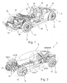
- An inventive motor vehicle 2 according to the Fig. 1 and 2 consists essentially of a designated in its entirety by 4 chassis frame and a designated in its entirety by 6 vehicle body.
- the out Fig. 1 apparent vehicle body 6 is designed for a motor vehicle 2 sporting expression in the manner of a so-called "2 + 2-seater" and has in its interior 14 two front seats 16 and two rear seats 18 with limited seating comfort.
- An end wall 20 delimits the interior space 14 with respect to an engine compartment 22.
- Behind the rear seats 18 is a luggage space 24.
- the vehicle body 6 has a plurality of carriers, for example, front side members 26 and lateral side members 28.
- a steering column 30 is arranged on the end wall 20, a steering column 30 is arranged.
- Fig. 2 shows a second embodiment of a motor vehicle 2 according to the invention with a strongly designed according to aerodynamic aspects outer skin.
- corresponding components of the motor vehicle 2 are denoted by the same reference numerals as in Fig. 1 , The other components identified by reference numbers of the motor vehicle 2 are below in connection with the Fig. 3 to 6 explained.
- the chassis frame 4 receives, inter alia, a front axle 8 and a rear axle 10, which are not shown in the figures.
- a front axle 8 and a rear axle 10 which are not shown in the figures.
- the wheels 12 of the front and rear axles 8 and 10 are shown.
- the Wheels 12 are comparatively narrow and tall compared to conventional motor vehicles.
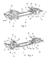
- the chassis frame 4 consists of the three modules front module 40, central module 42 and rear module 44.
- the central module 42 connects the front module 40 with the rear module 44.
- Front module 40 and rear module 44 have a support structure, for example, large-area cast components 41 and 45 has which, among other components of the front and rear axles 8 and 10, an engine mount, a steering gear, etc. are attached.
- the cast components 41 and 45 of front module 40 and rear module 44 are interconnected, inter alia, by extruded profiles 46 and 47.
- sheet metal components are provided between the lateral cast components 41 and 45 (see sheet metal component 43 in FIG Fig. 5 ).
- Front module 40 and / or rear module 44 may also be designed - wholly or partially - as a welded construction, especially in vehicles that are exposed to higher loads.
- the connection between the central module 42 and the two modules 40 and 44 is preferably done by screwing.
- a node-shaped connection module 48 is provided from a cast material. This connection module 48 may be designed differently depending on the design of the motor vehicle 2.
- the front module 40 is mainly formed by a right and a left cast member 41.
- the two cast components 41 accommodate the components of the front axle, an electric motor 50 and a plurality of other components. Also 41 attachment points for the vehicle body 6 are provided on the two cast components.
- Right and left cast component 41 are connected to one another via a plurality of extruded profiles, which are not visible in the figures, transverse to the direction of travel, as well as through the sheet metal component 43 on the end portion of the front module 40 facing the central module 42.
- the width of the front module 40 (and thus the front track width / Overall width of the motor vehicle 2) is determined by the length of the extruded profiles and the width of the sheet metal component 43.
- the electric motor 50 with a reduction gear 51, a power electronics 52, a charger 53, a distributor box 54 and a DC / DC converter 55 are arranged.
- a socket for connecting the charger is designated 59.
- heat exchangers 57 and 58 are provided.
- the electric motor 50 drives the front wheels 12 via the reduction gear 51.
- deformation elements 32 for connecting a front bumper 34 (see Fig. 1 ) intended.
- the rear module 44 consists essentially of a right and a left cast component 45, which are interconnected, inter alia, via extruded profiles 46 and 47.
- extruded profile 46 On the central module 42 facing the front side of the rear module 44.
- an extruded profile 47 at the top of the rear module 44 recognizable.
- the cast components 45 are interconnected, for example, by a sheet metal component.
- the width of the rear module 44 and thus the rear track of the motor vehicle 2 is determined by the length of the transversely to the direction of travel extending extrusions 46 and 47 and by the dimensioning of the lower-side sheet metal component.
- the rear module 44 carries two drive units 60 and 62, in the form of an internal combustion engine 60 and an electric motor 62.
- a transmission 64 preferably a dual-clutch transmission, is provided for driving the rear wheels 12.
- the electric motor 62 is disposed between the engine 60 and the transmission 64.
- the internal combustion engine 60 is designed, for example, as a diesel engine.
- a thermoelectric generator (TEG) is arranged in the muffler 66 of the exhaust system of the internal combustion engine 60.
- Deformation elements 36 engage a rear bumper 38.
- the central module 42 is designed in the form of a central tunnel and has a closed, approximately rectangular cross-section with high bending and torsional rigidity.
- the length of the central module 42 determines the wheelbase and the length of the motor vehicle 2.
- the central module 42 takes in Front and middle portion in a battery compartment 71, a plurality of electric batteries 70, which are formed as lithium-polymer batteries.
- the central module 42 has a fuel tank 72 for receiving diesel fuel.
- cooling water hoses 80 which connect the heat exchangers 57 and 58 to the power packs 50, 60 and 62 and to the power electronics 52, to the DC / DC converter 55 and to the storage space for the batteries 70.
- cooling water hoses 80 are provided between the two electric motors 50 and 62 on the one hand and the internal combustion engine 60 on the other hand in order to achieve preheating of the internal combustion engine 60 during electrical operation of the motor vehicle 2, so that the warm-up phase of the internal combustion engine 60 is shortened.
- a plurality of high voltage lines 82 between the batteries 70, the electrical components 52 to 55 and the two electric motors 40 and 62 can be seen.
- the lines between the fuel tank 72 and the tank filler neck 86 and the drive unit 60 are designated 84.
- the concentration of the lines 80, 82 and 84 on the chassis frame 4 simplifies the construction and assembly of the motor vehicle 2 according to the invention by the chassis frame 4 can be manufactured as a ready to drive unit, which is brought together after its completion with a completely pre-assembled vehicle body 6.
- high-voltage lines 82 can be dispensed with in the area of the vehicle body 6.
- Fig. 6 shows the individual components of the chassis frame 4 in abstract representation. Even if in Fig. 6 the components serving to drive the motor vehicle 2 are arranged on a chassis frame 4, which is composed of a front module 40, a central module 42 and a rear module 44, it is basically readily possible to use these components driving the motor vehicle 2 on a conventional vehicle to group, with the advantages already described above with regard to the drive.
- Front module 40 and rear module 44 carry not shown components of a front axle 8 and a rear axle 10, with relatively high and narrow wheels 12, which allow a low rolling resistance.
- the wheels 12 of the front axle 8 are driven by an electric motor 50 via an example catchy two-stage reduction gear 51.
- the electric motor 50 is designed, for example, as a hybrid synchronous motor.
- the wheels 12 of the rear axle 10 are driven by an internal combustion engine 60 and / or an electric motor 62 via a transmission 64.
- the components 60, 62 and 64 thus form a compact hybrid unit.
- the internal combustion engine 60 is, for example, a turbocharged 3-cylinder diesel engine.
- the transmission 64 may be formed, for example, as a 6-speed, fast-switching and consumption-optimized designed dual-clutch transmission.
- the electric motors 50 and / or 62 are powered by the batteries 70 housed in the battery compartment 71.
- a fuel tank 72 supplies the engine 60 with fuel.
- the drive of the motor vehicle 2 can take place via a single one of the drive units 50, 60 or 62. Likewise, the drive of the motor vehicle 2 can also take place simultaneously by two or all three drive units 50, 60 and 62, depending on the operating state or desired operating mode. Thus, a purely electric driving by the electric motors 50 and / or 62 is possible by driving only one axle 8 or 10 or by "electric four-wheel drive" on both axles 8 and 10. Long stretches are preferably handled by the engine 60. During acceleration, by adding the power and torques of two or all three drive units 50, 60 and 62, a faster propulsion can be generated.
- At least one of the electric motors 50 and 62 can be switched in overrun mode and / or during deceleration of the motor vehicle 2 as a generator and charge electrical current in the batteries 70.
- a thermoelectric generator in the muffler 66 of the exhaust system of the motor vehicle 2 also generates electrical energy.
- An inventive motor vehicle 2 is composed of a chassis frame 4 and a vehicle body 6 together.
- the chassis frame 6 is formed by a front module 40 and a rear module 44, which are connected to one another via a central module 42.
- the front module 40 accommodates a front axle 8, heat exchangers 57 and 58 and a drive unit 50 in the form of an electric motor.
- an internal combustion engine 60 and an electric motor 62 are provided in addition to the components of the rear axle 10.
- the central module 42 accommodates both the electric batteries 70 for supplying the two electric motors 50 and 62 and a fuel tank 72 for the internal combustion engine 60.
- the invention advantageously provides a universal vehicle architecture which makes it possible to produce several types of different motor vehicles 2 in series.
- This group of different motor vehicles 2 is based on a uniform modular chassis frame 4 with the three modules front module 40, central module 42 and rear module 44, wherein the individual types of motor vehicles 2 may nevertheless have a different external appearance.
- Front module 40, central module 42 and rear module 44 of the universal vehicle architecture each have at least one component whose length and / or width and / or height can be changed in a simple manner, for example, sectional extruded profiles 46 and 47.
Landscapes
- Engineering & Computer Science (AREA)
- Transportation (AREA)
- Mechanical Engineering (AREA)
- Chemical & Material Sciences (AREA)
- Combustion & Propulsion (AREA)
- Power Engineering (AREA)
- Life Sciences & Earth Sciences (AREA)
- Sustainable Development (AREA)
- Sustainable Energy (AREA)
- Manufacturing & Machinery (AREA)
- Arrangement Or Mounting Of Propulsion Units For Vehicles (AREA)
Description
- Die Erfindung betrifft ein Kraftfahrzeug mit einem Chassisrahmen. Derartige Kraftfahrzeuge sind beispielsweise aus der
EP 0 868 338 B1 , derEP 0 653 344 B1 , derWO 01/64501 A1 AT 208 243 B - Aus der
US 2008/019870 A1 ist ein Kraftfahrzeug mit einem Chassisrahmen bekannt, der ein Frontmodul und ein Heckmodul aufweist, die über ein Zentralmodul miteinander verbunden sind. Das Zentralmodul nimmt wenigstens einen Speicher auf, aus dem ein Antriebsaggregat des Kraftfahrzeugs mit Energie gespeist wird Sowohl das Frontmodul als auch das Heckmodul tragen jeweils wenigstens ein Antriebsaggregat. - Aufgabe der Erfindung ist es, das bekannte Kraftfahrzeug weiterzubilden.
- Diese Aufgabe wird durch ein Kraftfahrzeug mit den Merkmalen des Anspruchs 1 gelöst.
- Dem erfindungsgemäßen Kraftfahrzeug liegt eine äußerst variable Fahrzeugarchitektur zugrunde, mit der ein breites Spektrum unterschiedlicher Arten von Kraftfahrzeugen realisiert werden kann, einschließlich verschiedener Antriebskonzepte für diese Kraftfahrzeuge. Die Bandbreite innerhalb einer zugrundeliegenden Fahrzeugarchitektur umfasst beispielsweise Sportwagen, Fahrzeuge der Limousinen-, Fließheck- und Kombinationsbauart, Kraftfahrzeuge, die im urbanen Bereich vornehmlich für Transportzwecke und Kurzstreckenbetrieb ausgelegt sind und auch Fahrzeuge mit größerer Bodenfreiheit. Hierbei spielt neben der augenfälligen Prägung des Kraftfahrzeugs durch den Fahrzeugaufbau auch die Auslegung des Chassisrahmens eine wichtige Rolle.
- Die unterschiedlichen Arten von Kraftfahrzeugen und Antriebskonzepten können auf der Grundlage eines modular aufgebauten Chassisrahmens, der aus den drei Baugruppen Frontmodul, Zentralmodul und Heckmodul besteht, mit geringem Aufwand dargestellt werden. Vornehmlich wird hierbei die Breite von Front- und Heckmodul sowie die Breite und Länge des Zentralmoduls verändert. Somit kann aus einer gemeinsamen zugrundeliegenden Fahrzeugarchitektur dank des variablen Chassisrahmens eine Gruppe unterschiedlicher Fahrzeugarten, gegebenenfalls mit unterschiedlichen Antriebskonzepten, generiert werden, mit geringem konstruktivem und fertigungstechnischem Aufwand und damit mit niedrigen Herstellkosten.
- Werden die quer zur Fahrtrichtung verlaufenden Bauteile des Frontmoduls und/oder des Heckmoduls von Strangprofilen, insbesondere Strangpressprofilen, von Blechbauteilen etc. gebildet, kann in einfacher Weise eine Breitenanpassung der beiden Module durch Ablängen der Strangprofile bzw. entsprechendes Abkanten und Beschneiden der Blechbauteile erfolgen. Die Tragstruktur von Frontmodul und Heckmodul weist in einer vorteilhaften Ausführungsform der Erfindung als wesentliche Bestandteile vergleichsweise großflächige Gussbauteile auf, die die Elemente der Vorder- und Hinterachse tragen und außerdem eine Reihe weiterer Bauteile und Aggregate aufnehmen können, wie beispielsweise Antriebsaggregate und deren Peripherie, Getriebe, Wärmetauscher etc. Ferner sind Anbindungen für einen vorderen bzw. hinteren Stoßfänger vorgesehen. Die Gussbauteile sind hauptsächlich im seitlichen Bereich von Front- und/oder Heckmodul vorgesehen. Der Gepäckraum kann entweder am Chassisrahmen oder am Fahrzeugaufbau ausgebildet sein. Durch die Breitenvariation von Front- und Heckmodul kann die Spurweite und/oder die Breite des Kraftfahrzeugs verändert werden.
- Das Zentralmodul weist bevorzugt einen geschlossenen Querschnitt auf, um eine biege- und torsionssteife Verbindung von Frontmodul und Heckmodul zu gewährleisten. Veränderungen in der Länge des Zentralmoduls wirken sich auf den Radstand und/oder die Länge des Kraftfahrzeugs aus.
- Die Verbindung zwischen Frontmodul bzw. Heckmodul einerseits und dem Zentralmodul andererseits erfolgt bevorzugt durch eine Schraub- und/oder Klebeverbindung. Auch eine Schweißverbindung ist denkbar. Die Art der verwendeten Fügetechnologie hängt unter anderem von dem beim betreffenden Fahrzeugkonzept verwendeten Werkstoff ab. Zur Erhöhung der Variabilität kann zwischen dem Zentralmodul und dem Frontmodul bzw. Heckmodul ein Verbindungsmodul nach Art eines "Adapters" vorgesehen sein, um unterschiedliche Arten von Kraftfahrzeugen noch einfacher in modularer Weise nach Art eines Baukastens darstellen zu können. Das Verbindungsmodul besteht beispielsweise aus einem Strangprofil, einem Gussknoten etc.
- Chassisrahmen und Fahrzeugaufbau sind bevorzugt an wenigen definierten Stellen miteinander verbunden, beispielsweise durch eine Schraubverbindung. Selbstverständlich ist auch eine flächige Verbindung zwischen Chassisrahmen und Fahrzeugaufbau möglich, zum Beispiel durch Verklebung, gegebenenfalls mit zusätzlicher Verschraubung, oder durch Verschweißung.
- Erfindungsgemäß ist das Kraftfahrzeug mit einem Elektromotor an der Vorderachse und einer Kombination aus Verbrennungsmotor und Elektromotor an der Hinterachse konfiguriert. So ergeben sich beispielsweise bei einem Verbrennungsmotor an der Hinterachse kurze Leitungen zum Kraftstofftank und zu den Schalldämpfern der Abgasanlage.
- Weiterhin erfindungsgemäß ist das Frontmodul zur Anordnung eines oder mehrerer Wärmetauscher vorgesehen, beispielsweise für ein Heiz- und/oder Klimagerät für den Fahrzeuginnenraum, einen Kühlkreislauf für wenigstens ein Antriebsaggregat und/oder für eine Leistungselektronik und/oder für eine andere elektrische Baueinheit und/oder für eine elektrische Batterie. Insbesondere leistungsfähige Batterien, wie zum Beispiel Lithium-Polymer-Akkumulatoren, müssen ausreichend gekühlt werden.
- Unter dem Begriff "Antriebsaggregat" ist in Zusammenhang mit der vorliegenden Erfindung jede Art von Aggregat zu verstehen, das dem Antrieb des Kraftfahrzeugs dient, wie beispielsweise Verbrennungsmotore, Elektromotore, Gasturbinen etc. Die Verbrennungsmotore können für unterschiedliche fossile, biologische und synthetische Kohlenwasserstoff-Kraftstoffe sowie für Wasserstoff-Kraftstoff ausgelegt sein.
- Durch die Möglichkeit, die drei Baugruppen des Chassisrahmens innerhalb weiter Bereiche anzupassen zu können ist es in besonders vorteilhafter Weise möglich, Kraftfahrzeuge mit dem erfinderischen Antriebskonzept zu realisieren. Dem Zentralmodul kommt die Aufgabe der Speicherung eines Betriebsmediums zur Versorgung des wenigstens einen Antriebsaggregates zu. Das Zentralmodul kann hierzu in sehr variabler Weise ausgelegt werden und beispielsweise einen verhältnismäßig kleinen Tank für Benzin- oder Dieselkraftstoff, einen größeren Tank für Erdgas oder einen sehr voluminösen Tank für Wasserstoff aufnehmen. Auch elektrische Batterien können in kleinerer oder größerer Anzahl im Zentralmodul angeordnet werden. Hierzu kann die Breite und/oder die Länge und/oder die Höhe des Zentralmoduls variiert werden.
- Antriebsaggregate können in Baueinheit mit einem Getriebe ausgeführt sein, wie beispielsweise ein Elektromotor in einem Getriebegehäuse als Bestandteil eines so genannten Hybridantriebs, der durch einen Verbrennungsmotor ergänzt wird. Durch das Vorhandensein von Elektromotoren kann das Kraftfahrzeug elektrisch angetrieben und somit ohne Emissionen durch einen Verbrennungsmotor betrieben werden. Zusätzlich oder alternativ kann wenigstens ein Elektromotor zur Unterstützung eines Verbrennungsmotors herangezogen werden.
- Bei dem erfindungsgemäßen Kraftfahrzeug mit den Elektromotoren kann in Schubphasen und/oder beim Bremsen des Kraftfahrzeugs Energie rückgewonnen werden, indem wenigstens ein Elektromotor als Generator geschaltet wird. Die Rekuperation bei Einsatz des Elektromotors für Betriebsbremsungen liefert besonders hohe Ladeströme in die elektrische Batterie und mindert den Verschleiß der Komponenten der Reibungsbremse des Kraftfahrzeugs. Die Nutzung des Elektromotors als Betriebsbremse wirkt sich insbesondere bei erfindungsgemäßen Kraftfahrzeugen mit einem Elektromotor an der Vorderachse vorteilhaft aus, da bei Bremsvorgängen infolge der dynamischen Achslaständerung die Vorderachse stärker belastet wird und somit eine höhere Rekuperationsleistung erzielbar ist. Sind Elektromotore sowohl an der Vorder- als auch an der Hinterachse vorgesehen, kann in besonders wirkungsvoller Weise eine Rekuperation an beiden Fahrzeugachsen erfolgen.
- Durch die vielfältigen Möglichkeiten der Anordnung eines Speichers für ein Betriebsmedium zur Versorgung wenigstens eines Antriebsaggregats im Zentralmodul geht im Unterschied zu konventionellen Kraftfahrzeugen kein Bauraum zu Lasten der Insassen oder des Gepäckraums verloren. Während beispielsweise bei bekannten Fahrzeugen mit Wasserstoff- oder Erdgasantrieb, die auf einer konventionellen Fahrzeugarchitektur für ein Kraftfahrzeug mit Benzin- oder Dieselmotor basieren, ein beträchtlicher Teil des Gepäckraumes für den Kraftstofftank zur Verfügung gestellt werden muss, kann das Betriebsmedium bei dem erfindungsgemäßen Kraftfahrzeug in vorteilhafter Weise im Zentralmodul untergebracht werden. Auch ist das Zentralmodul in idealer Weise in der Lage, elektrische Batterien mit einer großen Kapazität aufzunehmen, die bei bekannten Fahrzeugen wiederum beträchtlichen Bauraum im Innenraum und/oder im Gepäckraum beanspruchen. Die Batterien sind beispielsweise als Lithium-Polymer-Akkumutatoren ausgebildet. Hierbei wird bevorzugt eine größere Anzahl einzelner kleinerer Lithium-Polymer-Akkumulatoren zusammengeschaltet. Alternativ können auch Lithium-Ionen-Akkumulatoren oder andere Ausführungsformen von Akkumulatoren mit Lithium-Metalloxiden zum Einsatz kommen. Grundsätzlich kommen alle elektrischen Speicher in Betracht, die eine ausreichende volumetrische und gravimetrische Energiedichte aufweisen. Angestrebt werden hierbei eine volumetrische Energiedichte von mindestens 150Wh/dm3 und eine gravimetrische Energiedichte von mindestens 120Wh/kg.
- Das Zentralmodul kann beispielsweise in Form eines Mitteltunnels ausgeführt sein. Bei einem derartigen relativ schmalen und hohen Zentralmodul ist eine tiefe Anordnung der Fahrzeugsitze zu beiden Seiten des Zentralmoduls möglich, so dass sich ein Kraftfahrzeug mit geringer Bauhöhe und niedrigem Schwerpunkt ergibt ("sportliche Ausprägung"). Alternativ kann das Zentralmodul auch über einen wesentlichen Teil der Breite des Kraftfahrzeugs reichen und in Form einer Tafel mit relativ geringer Höhe ausgebildet sein. Selbstverständlich kann die Höhe der Tafel auch größer ausfallen, wenn beispielsweise elektrische Batterien mit entsprechender Bauhöhe aufzunehmen sind. Bei der Auslegung des Zentralmoduls nach Art einer Tafel kann der Boden des zugehörigen Fahrzeugaufbaus weitestgehend flach ausgebildet werden ("urbane Ausprägung"). Hierdurch ergibt sich eine gegenüber der sportlichen Ausprägung vergleichsweise hohe Sitzposition. An dieser Stelle sei nochmals betont, dass beiden Arten von erfindungsgemäßen Kraftfahrzeugen dieselbe Fahrzeugarchitektur zugrunde liegt, mit gleichartig aufgebauten Front- und Heckmodulen, wobei die Anpassung in den Fahrzeugabmessungen und/oder die Fahrwerksabstimmung und/oder die Unterbringung unterschiedlicher Antriebsaggregate und/oder die Unterbringung unterschiedlicher Speicher für das Betriebsmedium durch geringe Abänderung von Front-, Zentral- und/oder Heckmodul ohne Weiteres und mit geringen Kosten realisierbar ist.
- Wie bereits oben ausgeführt, können Frontmodul und/oder Heckmodul eine Vielzahl von Bauteilen und Aggregaten tragen. Es können am Frontmodul und/oder Heckmodul elektrische Komponenten, die zum Betrieb des Elektromotors erforderlich sind, angeordnet sein. Hierbei handelt es sich beispielsweise um eine Leistungselektronik zur Ansteuerung des Elektromotors, ein Ladegerät, einen DC/DC-Wandler, eine Verteilerbox oder dergleichen. Weist das Kraftfahrzeug erfindungsgemäß sowohl am Frontmodul als auch am Heckmodul einen Elektromotor auf, können die genannten elektrischen Komponenten an einem der beiden Module gebündelt werden.
- Während das Bordnetz konventioneller Kraftfahrzeuge als Niedervoltnetz ausgelegt ist, arbeiten Kraftfahrzeuge mit einem Elektromotor als Antriebsaggregat in der Regel mit einer höheren Betriebsspannung. In einer vorteilhaften Ausführung der Erfindung ist das Hochspannung führende Leitungsnetz auf den Chassisrahmen beschränkt, so dass im Fahrzeugaufbau keine Hochspannung führenden Leitungen erforderlich sind.
- Mögliche Ausführungsbeispiele der Erfindung sind in den Figuren dargestellt und werden nachfolgend näher erläutert. Es zeigt:
- Fig. 1
- ein erstes Ausführungsbeispiel eines erfindungsgemäßen Kraftfahrzeugs in perspektivischer Darstellung,
- Fig. 2
- ein zweites Ausführungsbeispiel eines erfindungsgemäßen Kraftfahrzeugs in perspektivischer Darstellung,
- Fig. 3
- eine perspektivische Darstellung des Chassisrahmens der Kraftfahrzeuge von
Fig. 1 und 2 , - Fig. 4
- eine der
Fig. 3 entsprechende Darstellung des Chassisrahmens, mit selektiver Darstellung von Aggregaten und Leitungen, - Fig. 5
- eine der
Fig. 3 entsprechende Darstellung des Chassisrahmens, aus einem anderen Blickwinkel und - Fig. 6
- eine schematische Darstellung der Komponenten der Kraftfahrzeuge von
Fig. 1 und 2 . - Ein erfindungsgemäßes Kraftfahrzeug 2 gemäß den
Fig. 1 und 2 setzt sich im Wesentlichen aus einem in seiner Gesamtheit mit 4 bezeichneten Chassisrahmen und einem in seiner Gesamtheit mit 6 bezeichneten Fahrzeugaufbau zusammen. - Der aus
Fig. 1 ersichtliche Fahrzeugaufbau 6 ist für ein Kraftfahrzeug 2 sportlicher Ausprägung nach Art eines so genannten "2+2-Sitzers" ausgelegt und weist in seinem Innenraum 14 zwei Vordersitze 16 sowie zwei Rücksitze 18 mit eingeschränktem Sitzkomfort auf. Eine Stirnwand 20 grenzt den Innenraum 14 gegenüber einem Motorraum 22 ab. Hinter den Rücksitzen 18 befindet sich ein Gepäckraum 24. Der Fahrzeugaufbau 6 weist eine Mehrzahl von Trägern auf, beispielsweise vordere Längsträger 26 und seitliche Längsträger 28. An der Stirnwand 20 ist eine Lenksäule 30 angeordnet. -
Fig. 2 zeigt ein zweites Ausführungsbeispiel eines erfindungsgemäßen Kraftfahrzeugs 2 mit einer stark nach aerodynamischen Gesichtspunkten gestalteten Außenhaut. Dem ersten Ausführungsbeispiel gemäßFig. 1 entsprechenden Bestandteile des Kraftfahrzeugs 2 sind mit denselben Bezugszahlen bezeichnet wie inFig. 1 . Die weiteren mit Bezugszahlen gekennzeichneten Komponenten des Kraftfahrzeugs 2 sind nachfolgend in Zusammenhang mit denFig. 3 bis 6 erläutert. - Der Chassisrahmen 4 nimmt unter anderem eine Vorderachse 8 und eine Hinterachse 10 auf, die in den Figuren nicht dargestellt sind. In den
Fig. 1, 2 und6 sind lediglich die Räder 12 von Vorder- und Hinterachse 8 bzw. 10 dargestellt. Die Räder 12 sind im Vergleich zu konventionellen Kraftfahrzeugen vergleichsweise schmal und hoch ausgebildet. - Der Chassisrahmen 4 besteht aus den drei Baugruppen Frontmodul 40, Zentralmodul 42 und Heckmodul 44. Das Zentralmodul 42 verbindet das Frontmodul 40 mit dem Heckmodul 44. Frontmodul 40 und Heckmodul 44 weisen eine Tragstruktur auf, die beispielsweise großflächige Gussbauteile 41 bzw. 45 aufweist, an denen unter anderem Komponenten der Vorder- und Hinterachse 8 bzw. 10, eine Motorlagerung, ein Lenkgetriebe etc. befestigt sind. Die Gussbauteile 41 und 45 von Frontmodul 40 bzw. Heckmodul 44 werden unter anderem durch Strangprofile 46 und 47 miteinander verbunden. Außerdem sind zwischen den seitlichen Gussbauteilen 41 und 45 Blechbauteile vorgesehen (siehe Blechbauteil 43 in
Fig. 5 ). Frontmodul 40 und/oder Heckmodul 44 können auch - vollständig oder teilweise - als Schweißkonstruktion ausgeführt sein, vor allem bei Fahrzeugen, die höheren Belastungen ausgesetzt sind. Die Verbindung zwischen dem Zentralmodul 42 und den beiden Modulen 40 und 44 erfolgt bevorzugt durch Verschraubung. Hierbei ist beispielsweise zwischen dem Zentralmodul 42 und dem Heckmodul 44 ein knotenförmiges Verbindungsmodul 48 aus einem Gussmaterial vorgesehen. Dieses Verbindungsmodul 48 kann je nach Ausführung des Kraftfahrzeugs 2 unterschiedlich gestaltet sein. - Das Frontmodul 40 wird hauptsächlich von einem rechten und einem linken Gussbauteil 41 gebildet. Die beiden Gussbauteile 41 nehmen die Komponenten der Vorderachse, einen Elektromotor 50 sowie eine Vielzahl weiterer Komponenten auf. Auch sind an den beiden Gussbauteilen 41 Befestigungspunkte für den Fahrzeugaufbau 6 vorgesehen. Rechtes und linkes Gussbauteil 41 sind über mehrere in den Figuren nicht sichtbare, quer zur Fahrtrichtung verlaufende Strangprofile miteinander verbunden, ebenso wie durch das Blechbauteil 43 an dem dem Zentralmodul 42 zugewandten Endabschnitt des Frontmoduls 40. Die Breite des Frontmoduls 40 (und damit die vordere Spurbreite / Gesamtbreite des Kraftfahrzeugs 2) wird durch die Länge der Strangprofile und die Breite des Blechbauteils 43 bestimmt.
- Am Frontmodul 40 ist, wie insbesondere aus
Fig. 4 hervorgeht, der Elektromotor 50 mit einem Untersetzungsgetriebe 51, einer Leistungselektronik 52, einem Ladegerät 53, einer Verteilerbox 54 und einem DC/DC-Wandler 55 angeordnet. Eine Steckdose zum Anschluss des Ladegeräts ist mit 59 bezeichnet. Außerdem sind Wärmetauscher 57 und 58 vorgesehen. Der Elektromotor 50 treibt über das Untersetzungsgetriebe 51 die Vorderräder 12 an. Außerdem sind Deformationselemente 32 zur Anbindung eines vorderen Stoßfängers 34 (sieheFig. 1 ) vorgesehen. - Das Heckmodul 44 besteht im Wesentlichen aus einem rechten und einem linken Gussbauteil 45, die unter anderem über Strangprofile 46 und 47 miteinander verbunden sind. Von besonderer Bedeutung für die Tragstruktur des Heckmodul 44 ist hierbei das Strangprofil 46 an der dem Zentralmodul 42 zugewandten Stirnseite des Heckmoduls 44. Außerdem ist in den
Fig. 3 und5 ein Strangprofil 47 an der Oberseite des Heckmoduls 44 erkennbar. An der Unterseite des Heckmoduls 44 sind die Gussbauteile 45 beispielsweise durch ein Blechbauteil miteinander verbunden. Die Breite des Heckmoduls 44 und damit die hintere Spurweite des Kraftfahrzeugs 2 wird durch die Länge der quer zur Fahrtrichtung verlaufenden Strangprofile 46 und 47 sowie durch die Dimensionierung des unterseitigen Blechbauteils bestimmt. - Das Heckmodul 44 trägt zwei Antriebsaggregate 60 und 62, in Form eines Verbrennungsmotors 60 und eines Elektromotors 62. Außerdem ist ein Getriebe 64, bevorzugt ein Doppelkupplungsgetriebe, zum Antrieb der Hinterräder 12 vorgesehen. Der Elektromotor 62 ist zwischen dem Verbrennungsmotor 60 und dem Getriebe 64 angeordnet. Der Verbrennungsmotor 60 ist beispielsweise als Dieselmotor ausgebildet. Im Schalldämpfer 66 der Abgasanlage des Verbrennungsmotors 60 ist ein thermoelektrischer Generator (TEG) angeordnet. Deformationselemente 36 binden einen hinteren Stoßfänger 38 an.
- Das Zentralmodul 42 ist in Form eines Mitteltunnels ausgebildet und hat einen geschlossenen, etwa rechteckförmigen Querschnitt mit hoher Biege- und Torsionssteifigkeit. Die Länge des Zentralmoduls 42 bestimmt den Radstand und die Länge des Kraftfahrzeugs 2. In seinem Inneren nimmt das Zentralmodul 42 im vorderen und mittleren Bereich in einem Batteriefach 71 eine Mehrzahl von elektrischen Batterien 70 auf, die als Lithium-Polymer-Batterien ausgebildet sind. In seinem hinteren Bereich weist das Zentralmodul 42 einen Kraftstofftank 72 zur Aufnahme von Dieselkraftstoff auf.
- Die Darstellung der
Fig. 4 konzentriert sich auf elektrische Leitungen und Medienleitungen. Im Einzelnen handelt es sich hierbei um Kühlwasserschläuche 80, die die Wärmetauscher 57 und 58 mit den Antriebsaggregaten 50, 60 und 62 sowie mit der Leistungselektronik 52, mit dem DC/DC-Wandler 55 und mit dem Aufnahmeraum für die Batterien 70 verbinden. Ebenso sind Kühlwasserschläuche 80 zwischen den beiden Elektromotoren 50 und 62 einerseits und dem Verbrennungsmotor 60 andererseits vorgesehen, um bei elektrischem Betrieb des Kraftfahrzeugs 2 eine Vorwärmung des Verbrennungsmotors 60 zu erreichen, damit die Warmlaufphase des Verbrennungsmotors 60 verkürzt wird. Außerdem ist eine Vielzahl von Hochspannung führenden Leitungen 82 zwischen den Batterien 70, den elektrischen Komponenten 52 bis 55 und den beiden Elektromotoren 40 und 62 ersichtlich. Die Leitungen zwischen dem Kraftstofftank 72 und dem Tankeinfüllstutzen 86 sowie dem Antriebsaggregat 60 sind mit 84 bezeichnet. Die Konzentration der Leitungen 80, 82 und 84 auf den Chassisrahmen 4 vereinfacht den Aufbau und die Montage des erfindungsgemäßen Kraftfahrzeuges 2, indem der Chassisrahmen 4 als fahrfertige Einheit hergestellt werden kann, die nach ihrer Fertigstellung mit einem komplett vormontierten Fahrzeugaufbau 6 zusammengeführt wird. Außerdem kann im Bereich des Fahrzeugaufbaus 6 auf Hochspannung führende Leitungen 82 verzichtet werden. -
Fig. 6 zeigt die einzelnen Komponenten des Chassisrahmens 4 in abstrahierter Darstellung. Auch wenn inFig. 6 die dem Antrieb des Kraftfahrzeugs 2 dienenden Komponenten auf einem Chassisrahmen 4 angeordnet sind, der sich aus einem Frontmodul 40, einem Zentralmodul 42 und einem Heckmodul 44 zusammensetzt, ist es grundsätzlich ohne Weiteres möglich, diese dem Antrieb des Kraftfahrzeugs 2 dienenden Komponenten an einem konventionellen Fahrzeug zu gruppieren, mit den bereits oben beschriebenen Vorteilen hinsichtlich des Antriebs. - Frontmodul 40 und Heckmodul 44 tragen nicht näher dargestellte Bauteile einer Vorderachse 8 bzw. einer Hinterachse 10, mit vergleichsweise hohen und schmalen Rädern 12, die einen niedrigen Rollwiderstand ermöglichen. Die Räder 12 der Vorderachse 8 werden von einem Elektromotor 50 über ein beispielsweise eingängiges zweistufiges Untersetzungsgetriebe 51 angetrieben. Der Elektromotor 50 ist zum Beispiel als Hybridsynchronmotor ausgebildet. Die Räder 12 der Hinterachse 10 werden von einem Verbrennungsmotor 60 und/oder einem Elektromotor 62 über ein Getriebe 64 angetrieben. Die Komponenten 60, 62 und 64 bildet somit eine kompakte Hybrideinheit. Bei dem Verbrennungsmotor 60 handelt es sich beispielsweise um einen 3-Zylinder-Dieselmotor mit Turboaufladung. Das Getriebe 64 kann zum Beispiel als 6-gängiges, schnell schaltendes und verbrauchsoptimiert ausgelegtes Doppelkupplungsgetriebe ausgebildet sein.
- Die Elektromotore 50 und/oder 62 werden von den im Batteriefach 71 untergebrachten Batterien 70 gespeist. Ein Kraftstofftank 72 versorgt den Verbrennungsmotor 60 mit Kraftstoff.
- Der Antrieb des Kraftfahrzeugs 2 kann über ein einzelnes der Antriebsaggregate 50, 60 oder 62 erfolgen. Ebenso kann der Antrieb des Kraftfahrzeugs 2 auch von zwei oder von allen drei Antriebsaggregaten 50, 60 bzw. 62 gleichzeitig erfolgen, je nach Betriebszustand oder gewünschter Betriebsart. So ist ein rein elektrisches Fahren durch die Elektromotore 50 und/oder 62 möglich, durch Antrieb nur einer Achse 8 bzw. 10 oder durch "elektrischen Allradantrieb" an beiden Achsen 8 und 10. Lange Strecken werden bevorzugt vom Verbrennungsmotor 60 bewältigt. Beim Beschleunigen kann durch Addition der Leistung und Drehmomente von zwei oder allen drei Antriebsaggregaten 50, 60 bzw. 62 ein schnellerer Vortrieb erzeugt werden. Außerdem kann wenigstens einer der Elektromotore 50 und 62 im Schubbetrieb und/oder beim Abbremsen des Kraftfahrzeugs 2 als Generator geschaltet werden und elektrischen Strom in die Batterien 70 laden. Ein thermoelektrischer Generator im Schalldämpfer 66 der Abgasanlage des Kraftfahrzeugs 2 erzeugt ebenfalls elektrische Energie.
- Zusammenfassend lässt sich die Erfindung wie folgt beschreiben: Ein erfindungsgemäßes Kraftfahrzeug 2 setzt sich aus einem Chassisrahmen 4 und einem Fahrzeugaufbau 6 zusammen. Der Chassisrahmen 6 wird von einem Frontmodul 40 und einem Heckmodul 44 gebildet, die über ein Zentralmodul 42 miteinander verbunden sind. Das Frontmodul 40 nimmt eine Vorderachse 8, Wärmetauscher 57 und 58 sowie ein Antriebsaggregat 50 in Form eines Elektromotors auf. Am Heckmodul 44 sind neben den Komponenten der Hinterachse 10 ein Verbrennungsmotor 60 sowie ein Elektromotor 62 vorgesehen. Das Zentralmodul 42 nimmt sowohl die elektrischen Batterien 70 zur Versorgung der beiden Elektromotore 50 und 62 als auch einen Kraftstofftank 72 für den Verbrennungsmotor 60 auf. Durch die beiden Elektromotore 50 und 62 an Vorder-und Hinterachse 8 bzw. 10 kann in einfacher Weise ein "elektrischer Allradantrieb" realisiert werden.
- Die Erfindung stellt in vorteilhafter Weise eine universelle Fahrzeugarchitektur bereit, die es ermöglicht, mehrere Arten unterschiedlicher Kraftfahrzeuge 2 serienmäßig herzustellen. Diese Gruppe verschiedener Kraftfahrzeuge 2 baut auf einem einheitlichen modularen Chassisrahmen 4 mit den drei Baugruppen Frontmodul 40, Zentralmodul 42 und Heckmodul 44 auf, wobei die einzelnen Arten von Kraftfahrzeugen 2 dennoch ein unterschiedliches äußeres Erscheinungsbild haben können. Frontmodul 40, Zentralmodul 42 und Heckmodul 44 der universellen Fahrzeugarchitektur weisen jeweils wenigstens ein Bauteil auf, dessen Länge und/oder Breite und/oder Höhe in einfacher Weise veränderbar ist, beispielsweise ablängbare Strangprofile 46 und 47.
Claims (8)
- Kraftfahrzeug (2) mit einem Chassisrahmen (4), der ein Frontmodul (40) und ein Heckmodul (44) aufweist, die über ein Zentralmodul (42) miteinander verbunden sind, das wenigstens einen Speicher (70, 72) aufnimmt, aus dem ein Antriebsaggregat (50, 60, 62) des Kraftfahrzeugs (2) mit Energie gespeist wird, wobei sowohl das Frontmodul (40) als auch das Heckmodul (44) jeweils wenigstens ein Antriebsaggregat (50, 60, 62) tragen,
dadurch gekennzeichnet, dass das Frontmodul (40) einen Elektromotor (50) und das Heckmodul (44) eine Kombination aus Verbrennungsmotor (60) und Elektromotor (62) trägt, wobei das Frontmodul (40) wenigstens einen Wärmetauscher (58) für die Antriebsaggregate (50, 60, 62) und/oder eine Leistungselektronik (52) und/oder weitere elektrische Komponenten (53 bis 55) und/oder ein Heizgerät und/oder ein Klimagerät aufweist. - Kraftfahrzeug nach Anspruch 1,
dadurch gekennzeichnet, dass das Zentralmodul (42) nach Art eines Mitteltunnels ausgeführt ist. - Kraftfahrzeug nach Anspruch 1,
dadurch gekennzeichnet, dass das Zentralmodul (42) nach Art einer sich über einen wesentlichen Teil der Breite des Kraftfahrzeugs (2) erstreckenden Tafel ausgeführt ist. - Kraftfahrzeug nach einem der vorangegangenen Ansprüche,
dadurch gekennzeichnet, dass das Zentralmodul (42) einen geschlossenen Querschnitt aufweist. - Kraftfahrzeug nach einem der vorangegangenen Ansprüche,
dadurch gekennzeichnet, dass das Front- und/oder das Heckmodul (40; 44) ein rechtes und ein linkes Gussbauteil (41; 45) aufweisen, die durch wenigstens ein quer zur Fahrtrichtung verlaufendes Bauteil (43; 46; 47) miteinander verbunden sind, das je nach Art des Kraftfahrzeugs (2) eine unterschiedliche Länge aufweisen kann. - Kraftfahrzeug nach einem der vorangegangenen Ansprüche,
dadurch gekennzeichnet, dass zwischen dem Zentralmodul (42) und dem Front- bzw. Heckmodul (40; 44) wenigstens ein separates Verbindungsmodul (48) vorgesehen ist. - Kraftfahrzeug nach einem der vorangegangenen Ansprüche,
dadurch gekennzeichnet, dass der Verbrennungsmotor einen Generator zum Laden einer elektrischen Batterie antreibt. - Kraftfahrzeug nach einem der vorangegangenen Ansprüche,
dadurch gekennzeichnet, dass der Chassisrahmen (4) die Hochspannung führenden Leitungen (82) des Kraftfahrzeugs (2) aufnimmt.
Applications Claiming Priority (2)
| Application Number | Priority Date | Filing Date | Title |
|---|---|---|---|
| DE102009038834A DE102009038834A1 (de) | 2009-08-25 | 2009-08-25 | Kraftfahrzeug |
| PCT/EP2010/062306 WO2011023681A1 (de) | 2009-08-25 | 2010-08-24 | Kraftfahrzeug |
Publications (2)
| Publication Number | Publication Date |
|---|---|
| EP2470390A1 EP2470390A1 (de) | 2012-07-04 |
| EP2470390B1 true EP2470390B1 (de) | 2015-06-03 |
Family
ID=43066715
Family Applications (1)
| Application Number | Title | Priority Date | Filing Date |
|---|---|---|---|
| EP10747188.0A Not-in-force EP2470390B1 (de) | 2009-08-25 | 2010-08-24 | Kraftfahrzeug |
Country Status (3)
| Country | Link |
|---|---|
| EP (1) | EP2470390B1 (de) |
| DE (1) | DE102009038834A1 (de) |
| WO (1) | WO2011023681A1 (de) |
Cited By (1)
| Publication number | Priority date | Publication date | Assignee | Title |
|---|---|---|---|---|
| WO2017168399A1 (en) * | 2016-03-31 | 2017-10-05 | Bombardier Recreational Products Inc. | Vehicle having separable driver and propulsion modules |
Families Citing this family (27)
| Publication number | Priority date | Publication date | Assignee | Title |
|---|---|---|---|---|
| GB2483272B (en) * | 2010-09-02 | 2013-03-20 | Lightning Car Company Ltd | Electric motor vehicle |
| DE102011003258A1 (de) * | 2011-01-27 | 2012-08-02 | Rücker GmbH | Baukastensystem zum alternativen Bau eines Elektropersonenkraftfahrzeugs oder eines Elektronutzfahrzeugs |
| FR2973301B1 (fr) * | 2011-03-29 | 2013-05-10 | Renault Sa | Systeme de cogeneration d'energie pour vehicule automobile electrique |
| DE102011001861B4 (de) * | 2011-04-07 | 2024-12-05 | Dr. Ing. H.C. F. Porsche Ag | Tragstruktur für ein Kraftfahrzeug und Kraftfahrzeug |
| FR2975350B1 (fr) * | 2011-05-17 | 2013-05-31 | Renault Sa | Berceau arriere pour vehicule automobile electrique ou hybride, agencement arriere de vehicule et vehicule |
| FR2976226A1 (fr) * | 2011-06-10 | 2012-12-14 | Muses | Structure de chassis destinee a supporter un habitacle pour former un vehicule automobile a propulsion electrique et vehicule automobile comportant une telle structure de chassis. |
| DE102011078265B3 (de) | 2011-06-29 | 2012-06-21 | Bayerische Motoren Werke Aktiengesellschaft | Fahrzeug mit einem als tragende Strukturkomponente ausgebildeten Gehäuse eines elektrischen Energiespeichers |
| DE102011113799A1 (de) | 2011-09-20 | 2013-03-21 | Volkswagen Aktiengesellschaft | Batteriekasten, Elektro- oder Hybridfahrzeug und Verfahren zur Montage eines Batteriekastens |
| DE102012205982A1 (de) | 2012-04-12 | 2013-10-17 | Bayerische Motoren Werke Aktiengesellschaft | Funktionsintegriertes Zentralmodul |
| FR2990387A1 (fr) * | 2012-05-09 | 2013-11-15 | Peugeot Citroen Automobiles Sa | Procede d'installation d'au moins une canalisation menagee sous une caisse d'un vehicule automobile |
| DE102012105141B4 (de) * | 2012-07-30 | 2024-08-29 | Dr. Ing. H.C. F. Porsche Aktiengesellschaft | Befestigungsanordnung für ein Ladegerät einer Batterie in einer Fahrzeugkarosserie |
| DE102014203506A1 (de) | 2013-03-05 | 2014-09-11 | Volkswagen Aktiengesellschaft | Batterieanordnung und Fahrzeug mit einer solchen |
| DE102013106085B4 (de) | 2013-06-12 | 2024-05-23 | Dr. Ing. H.C. F. Porsche Aktiengesellschaft | Lagerrahmen für ein elektrisch angetriebenes Kraftfahrzeug |
| DE102014203570B4 (de) * | 2014-02-27 | 2019-03-28 | Volkswagen Aktiengesellschaft | Fahrzeugkarosserie für ein Hybridfahrzeug |
| ES2932802T3 (es) * | 2015-12-24 | 2023-01-26 | Softcar Sa | Arquitectura de vehículo |
| DE102016102250B4 (de) * | 2016-02-10 | 2025-12-11 | Dr. Ing. H.C. F. Porsche Aktiengesellschaft | Strukturverbund für einen Vorderwagen eines Kraftfahrzeugs |
| DE102016008591B3 (de) * | 2016-07-13 | 2017-08-24 | Audi Ag | Verfahren und Vorrichtung zum Schutz einer Batterie eines Fahrzeugs |
| US10137769B2 (en) * | 2017-01-29 | 2018-11-27 | Stephen Kariniemi | Center mounted air chute for a rear mounted engine |
| DE102017213816A1 (de) * | 2017-08-08 | 2019-02-14 | Bayerische Motoren Werke Aktiengesellschaft | Kraftfahrzeug mit Hybridantrieb |
| JP7247815B2 (ja) * | 2019-08-23 | 2023-03-29 | マツダ株式会社 | 電気機器の車載構造 |
| DE102019124916A1 (de) * | 2019-09-16 | 2021-03-18 | Bayerische Motoren Werke Aktiengesellschaft | Verfahren zum Fügen eines Antriebsstrangs mit einem Fahrzeugaufbau |
| WO2022023443A2 (de) * | 2020-07-29 | 2022-02-03 | Piëch Ip Ag | Kraftfahrzeug in modulbauweise sowie diverse module für ein solches kraftfahrzeug |
| DE102021126411A1 (de) | 2021-10-12 | 2023-04-13 | Bpw Bergische Achsen Kommanditgesellschaft | Elektrisch angetriebenes Nutzfahrzeug, sowie Hochvoltantriebssystem für ein Nutzfahrzeug |
| FR3144593A1 (fr) * | 2022-12-30 | 2024-07-05 | Valeo Embrayages | Châssis avec système hydraulique |
| FR3144590A1 (fr) * | 2022-12-30 | 2024-07-05 | Valeo Embrayages | Châssis avec systèmes de fixation améliorés |
| FR3144594A1 (fr) * | 2022-12-30 | 2024-07-05 | Valeo Embrayages | Châssis avec systèmes de fixation améliorés |
| FR3151286B1 (fr) * | 2023-07-19 | 2025-07-25 | Renault Sas | Méthode d’assemblage de véhicules automobiles électriques et installation de mise en œuvre |
Family Cites Families (16)
| Publication number | Priority date | Publication date | Assignee | Title |
|---|---|---|---|---|
| AT208243B (de) | 1958-07-25 | 1960-03-25 | Steyr Daimler Puch Ag | Kraftfahrzeug |
| FR2249544A5 (en) * | 1973-10-30 | 1975-05-23 | Gadriot Roland | Vehicle with battery electric propulsion - has plastics chassis members which also act as battery containers reducing weight |
| EP0566840A1 (de) * | 1992-04-18 | 1993-10-27 | Volkswagen Aktiengesellschaft | Kraftfahrzeug, insbesondere Personenkraftwagen |
| DE4243455A1 (de) * | 1992-12-22 | 1994-06-23 | Berghauer Bgh Service Gmbh | Grundeinheit für ein Kraftfahrzeug |
| FR2712555B1 (fr) | 1993-11-16 | 1996-01-19 | Smh Management Services Ag | Châssis pour véhicule automobile. |
| IT232382Y1 (it) * | 1994-04-22 | 1999-12-17 | Fiat Auto Spa | Attrezzatura per l'assemblaggio di una pluralita' di telai ausiliari per autovetture. |
| FR2742403B1 (fr) | 1995-12-18 | 1998-03-06 | Sbarro Fransceco | Vehicule automobile a chassis poutre |
| DE29606224U1 (de) * | 1996-04-04 | 1996-07-04 | CARBIKE Leichtfahrzeuge GmbH & Co KG, 88131 Lindau | Vierrädriges, vollverkleidetes Leichtfahrzeug |
| JP3599075B2 (ja) * | 1996-04-23 | 2004-12-08 | 本田技研工業株式会社 | 小型車両の車体フレーム装置 |
| US5934397A (en) * | 1997-01-28 | 1999-08-10 | Schaper; Douglas | Modular land vehicle |
| WO2001064501A1 (de) | 2000-03-01 | 2001-09-07 | Bayerische Motoren Werke Aktiengesellschaft | Fahrschemel für ein kraftfahrzeug |
| DE10154353B4 (de) * | 2000-11-06 | 2012-10-18 | General Motors Corp. | Modularer Fahrzeugaufbau |
| DE102005052307A1 (de) * | 2005-11-01 | 2007-05-03 | Otte, Hans Hermann | Fahrzeug mit einem elektrischen Antriebssystem und einem Brennstoffzellensystem |
| US20080179870A1 (en) * | 2007-01-26 | 2008-07-31 | Theodore & Associates Llc | Universal chassis |
| ITMI20072355A1 (it) * | 2007-12-17 | 2009-06-18 | Automotive Res Technology & St | Struttura di quadriciclo a motore. |
| WO2009114154A1 (en) * | 2008-03-11 | 2009-09-17 | Xr3 Motors, Llc | Hybrid vehicle |
-
2009
- 2009-08-25 DE DE102009038834A patent/DE102009038834A1/de not_active Withdrawn
-
2010
- 2010-08-24 WO PCT/EP2010/062306 patent/WO2011023681A1/de not_active Ceased
- 2010-08-24 EP EP10747188.0A patent/EP2470390B1/de not_active Not-in-force
Cited By (4)
| Publication number | Priority date | Publication date | Assignee | Title |
|---|---|---|---|---|
| WO2017168399A1 (en) * | 2016-03-31 | 2017-10-05 | Bombardier Recreational Products Inc. | Vehicle having separable driver and propulsion modules |
| CN109070957A (zh) * | 2016-03-31 | 2018-12-21 | 庞巴迪动力产品公司 | 具有可分离的驾驶员模块和推进模块的车辆 |
| US10967721B2 (en) | 2016-03-31 | 2021-04-06 | Bombardier Recreational Products Inc. | Vehicle having separable driver and propulsion modules |
| CN109070957B (zh) * | 2016-03-31 | 2021-09-17 | 庞巴迪动力产品公司 | 具有可分离的驾驶员模块和推进模块的车辆 |
Also Published As
| Publication number | Publication date |
|---|---|
| EP2470390A1 (de) | 2012-07-04 |
| DE102009038834A1 (de) | 2011-03-03 |
| WO2011023681A1 (de) | 2011-03-03 |
Similar Documents
| Publication | Publication Date | Title |
|---|---|---|
| EP2470390A1 (de) | Kraftfahrzeug | |
| DE102017130399A1 (de) | Batterie-pack-befestigungsarchitektur mit scherplatte für elektroantriebsmotoren | |
| DE69702231T2 (de) | Serien- Hybrid- Fahrzeug und Antriebseinheit dafür | |
| DE102010007414B4 (de) | Einbaumodul für ein Hybridfahrzeug | |
| DE69602964T2 (de) | Ultraleichtes strassenfahrzeug | |
| DE212020000508U1 (de) | Universelle Schnellwechsel-Leistungsbatterie für Neuenergiefahrzeuge | |
| DE102016215655A1 (de) | Strukturell integrierte antriebsbatterie | |
| EP4200195B1 (de) | Gruppe von kraftfahrzeugen | |
| DE102022204040A1 (de) | Elektrofahrzeug-batterieeinheit und batterieeinheitsinstallationsverfahren | |
| WO2021148367A1 (de) | Nutzfahrzeug mit brennstoffzelleneinrichtung | |
| EP2547540B1 (de) | Kraftfahrzeug | |
| DE202016006076U1 (de) | Elektrisch angetriebener Anhänger/Auflieger und System umfassend ein elektrisches angetriebenes Kraftfahrzeug und einen elektrischen angetriebenen Anhänger | |
| DE112013005203T5 (de) | Elektrisches Fahrzeug | |
| DE102013004837A1 (de) | Nutzfahrzeug sowie Baukastensystem für ein Nutzfahrzeug | |
| DE19926607A1 (de) | Modular aufgebautes Fahrzeug | |
| DE102009048573A1 (de) | Kraftfahrzeug, insbesondere Dreirad | |
| DE102016103481B4 (de) | Verfahren zum Umbau eines Fahrzeuges und Fahrzeug | |
| DE102021127709A1 (de) | Stützbaugruppe und stützverfahren für batterieanordnung der oberen schicht einer traktionsbatterie | |
| EP1925491A2 (de) | Hybridantrieb | |
| WO2011044964A1 (de) | Fahrzeug mit einem brennstoffzellensystem | |
| DE4002890C2 (de) | Gelenkomnibus | |
| DE102024101656B3 (de) | Heckantriebsmodul eines Fahrzeugs | |
| EP2366604A1 (de) | Geländegängiges Personenkraftfahrzeug | |
| DE102010033431A1 (de) | Kraftfahrzeug und Verfahren zum Antreiben eines Kraftfahrzeugs | |
| AT13198U1 (de) | Gelenkbus |
Legal Events
| Date | Code | Title | Description |
|---|---|---|---|
| PUAI | Public reference made under article 153(3) epc to a published international application that has entered the european phase |
Free format text: ORIGINAL CODE: 0009012 |
|
| 17P | Request for examination filed |
Effective date: 20111125 |
|
| AK | Designated contracting states |
Kind code of ref document: A1 Designated state(s): AL AT BE BG CH CY CZ DE DK EE ES FI FR GB GR HR HU IE IS IT LI LT LU LV MC MK MT NL NO PL PT RO SE SI SK SM TR |
|
| DAX | Request for extension of the european patent (deleted) | ||
| GRAP | Despatch of communication of intention to grant a patent |
Free format text: ORIGINAL CODE: EPIDOSNIGR1 |
|
| INTG | Intention to grant announced |
Effective date: 20140123 |
|
| 17Q | First examination report despatched |
Effective date: 20140416 |
|
| GRAP | Despatch of communication of intention to grant a patent |
Free format text: ORIGINAL CODE: EPIDOSNIGR1 |
|
| GRAS | Grant fee paid |
Free format text: ORIGINAL CODE: EPIDOSNIGR3 |
|
| INTG | Intention to grant announced |
Effective date: 20150410 |
|
| GRAA | (expected) grant |
Free format text: ORIGINAL CODE: 0009210 |
|
| AK | Designated contracting states |
Kind code of ref document: B1 Designated state(s): AL AT BE BG CH CY CZ DE DK EE ES FI FR GB GR HR HU IE IS IT LI LT LU LV MC MK MT NL NO PL PT RO SE SI SK SM TR |
|
| REG | Reference to a national code |
Ref country code: GB Ref legal event code: FG4D Free format text: NOT ENGLISH |
|
| REG | Reference to a national code |
Ref country code: CH Ref legal event code: EP |
|
| REG | Reference to a national code |
Ref country code: AT Ref legal event code: REF Ref document number: 729726 Country of ref document: AT Kind code of ref document: T Effective date: 20150715 Ref country code: IE Ref legal event code: FG4D Free format text: LANGUAGE OF EP DOCUMENT: GERMAN |
|
| REG | Reference to a national code |
Ref country code: DE Ref legal event code: R096 Ref document number: 502010009642 Country of ref document: DE |
|
| PG25 | Lapsed in a contracting state [announced via postgrant information from national office to epo] |
Ref country code: LT Free format text: LAPSE BECAUSE OF FAILURE TO SUBMIT A TRANSLATION OF THE DESCRIPTION OR TO PAY THE FEE WITHIN THE PRESCRIBED TIME-LIMIT Effective date: 20150603 Ref country code: ES Free format text: LAPSE BECAUSE OF FAILURE TO SUBMIT A TRANSLATION OF THE DESCRIPTION OR TO PAY THE FEE WITHIN THE PRESCRIBED TIME-LIMIT Effective date: 20150603 Ref country code: NO Free format text: LAPSE BECAUSE OF FAILURE TO SUBMIT A TRANSLATION OF THE DESCRIPTION OR TO PAY THE FEE WITHIN THE PRESCRIBED TIME-LIMIT Effective date: 20150903 Ref country code: FI Free format text: LAPSE BECAUSE OF FAILURE TO SUBMIT A TRANSLATION OF THE DESCRIPTION OR TO PAY THE FEE WITHIN THE PRESCRIBED TIME-LIMIT Effective date: 20150603 Ref country code: HR Free format text: LAPSE BECAUSE OF FAILURE TO SUBMIT A TRANSLATION OF THE DESCRIPTION OR TO PAY THE FEE WITHIN THE PRESCRIBED TIME-LIMIT Effective date: 20150603 |
|
| REG | Reference to a national code |
Ref country code: NL Ref legal event code: MP Effective date: 20150603 |
|
| REG | Reference to a national code |
Ref country code: LT Ref legal event code: MG4D |
|
| PG25 | Lapsed in a contracting state [announced via postgrant information from national office to epo] |
Ref country code: GR Free format text: LAPSE BECAUSE OF FAILURE TO SUBMIT A TRANSLATION OF THE DESCRIPTION OR TO PAY THE FEE WITHIN THE PRESCRIBED TIME-LIMIT Effective date: 20150904 Ref country code: BG Free format text: LAPSE BECAUSE OF FAILURE TO SUBMIT A TRANSLATION OF THE DESCRIPTION OR TO PAY THE FEE WITHIN THE PRESCRIBED TIME-LIMIT Effective date: 20150903 Ref country code: LV Free format text: LAPSE BECAUSE OF FAILURE TO SUBMIT A TRANSLATION OF THE DESCRIPTION OR TO PAY THE FEE WITHIN THE PRESCRIBED TIME-LIMIT Effective date: 20150603 |
|
| PG25 | Lapsed in a contracting state [announced via postgrant information from national office to epo] |
Ref country code: EE Free format text: LAPSE BECAUSE OF FAILURE TO SUBMIT A TRANSLATION OF THE DESCRIPTION OR TO PAY THE FEE WITHIN THE PRESCRIBED TIME-LIMIT Effective date: 20150603 |
|
| PG25 | Lapsed in a contracting state [announced via postgrant information from national office to epo] |
Ref country code: IS Free format text: LAPSE BECAUSE OF FAILURE TO SUBMIT A TRANSLATION OF THE DESCRIPTION OR TO PAY THE FEE WITHIN THE PRESCRIBED TIME-LIMIT Effective date: 20151003 Ref country code: RO Free format text: LAPSE BECAUSE OF NON-PAYMENT OF DUE FEES Effective date: 20150603 Ref country code: PT Free format text: LAPSE BECAUSE OF FAILURE TO SUBMIT A TRANSLATION OF THE DESCRIPTION OR TO PAY THE FEE WITHIN THE PRESCRIBED TIME-LIMIT Effective date: 20151006 Ref country code: PL Free format text: LAPSE BECAUSE OF FAILURE TO SUBMIT A TRANSLATION OF THE DESCRIPTION OR TO PAY THE FEE WITHIN THE PRESCRIBED TIME-LIMIT Effective date: 20150603 Ref country code: CZ Free format text: LAPSE BECAUSE OF FAILURE TO SUBMIT A TRANSLATION OF THE DESCRIPTION OR TO PAY THE FEE WITHIN THE PRESCRIBED TIME-LIMIT Effective date: 20150603 Ref country code: SK Free format text: LAPSE BECAUSE OF FAILURE TO SUBMIT A TRANSLATION OF THE DESCRIPTION OR TO PAY THE FEE WITHIN THE PRESCRIBED TIME-LIMIT Effective date: 20150603 |
|
| REG | Reference to a national code |
Ref country code: DE Ref legal event code: R097 Ref document number: 502010009642 Country of ref document: DE |
|
| PG25 | Lapsed in a contracting state [announced via postgrant information from national office to epo] |
Ref country code: MC Free format text: LAPSE BECAUSE OF FAILURE TO SUBMIT A TRANSLATION OF THE DESCRIPTION OR TO PAY THE FEE WITHIN THE PRESCRIBED TIME-LIMIT Effective date: 20150603 Ref country code: LU Free format text: LAPSE BECAUSE OF FAILURE TO SUBMIT A TRANSLATION OF THE DESCRIPTION OR TO PAY THE FEE WITHIN THE PRESCRIBED TIME-LIMIT Effective date: 20150824 |
|
| REG | Reference to a national code |
Ref country code: CH Ref legal event code: PL |
|
| PLBE | No opposition filed within time limit |
Free format text: ORIGINAL CODE: 0009261 |
|
| STAA | Information on the status of an ep patent application or granted ep patent |
Free format text: STATUS: NO OPPOSITION FILED WITHIN TIME LIMIT |
|
| PG25 | Lapsed in a contracting state [announced via postgrant information from national office to epo] |
Ref country code: CH Free format text: LAPSE BECAUSE OF NON-PAYMENT OF DUE FEES Effective date: 20150831 Ref country code: IT Free format text: LAPSE BECAUSE OF FAILURE TO SUBMIT A TRANSLATION OF THE DESCRIPTION OR TO PAY THE FEE WITHIN THE PRESCRIBED TIME-LIMIT Effective date: 20150603 Ref country code: LI Free format text: LAPSE BECAUSE OF NON-PAYMENT OF DUE FEES Effective date: 20150831 Ref country code: DK Free format text: LAPSE BECAUSE OF FAILURE TO SUBMIT A TRANSLATION OF THE DESCRIPTION OR TO PAY THE FEE WITHIN THE PRESCRIBED TIME-LIMIT Effective date: 20150603 |
|
| 26N | No opposition filed |
Effective date: 20160304 |
|
| GBPC | Gb: european patent ceased through non-payment of renewal fee |
Effective date: 20150903 |
|
| PG25 | Lapsed in a contracting state [announced via postgrant information from national office to epo] |
Ref country code: SI Free format text: LAPSE BECAUSE OF FAILURE TO SUBMIT A TRANSLATION OF THE DESCRIPTION OR TO PAY THE FEE WITHIN THE PRESCRIBED TIME-LIMIT Effective date: 20150603 |
|
| REG | Reference to a national code |
Ref country code: IE Ref legal event code: MM4A |
|
| REG | Reference to a national code |
Ref country code: FR Ref legal event code: ST Effective date: 20160429 |
|
| PG25 | Lapsed in a contracting state [announced via postgrant information from national office to epo] |
Ref country code: GB Free format text: LAPSE BECAUSE OF NON-PAYMENT OF DUE FEES Effective date: 20150903 Ref country code: IE Free format text: LAPSE BECAUSE OF NON-PAYMENT OF DUE FEES Effective date: 20150824 |
|
| PG25 | Lapsed in a contracting state [announced via postgrant information from national office to epo] |
Ref country code: FR Free format text: LAPSE BECAUSE OF NON-PAYMENT OF DUE FEES Effective date: 20150831 |
|
| REG | Reference to a national code |
Ref country code: AT Ref legal event code: MM01 Ref document number: 729726 Country of ref document: AT Kind code of ref document: T Effective date: 20150824 |
|
| PG25 | Lapsed in a contracting state [announced via postgrant information from national office to epo] |
Ref country code: AT Free format text: LAPSE BECAUSE OF NON-PAYMENT OF DUE FEES Effective date: 20150824 |
|
| PG25 | Lapsed in a contracting state [announced via postgrant information from national office to epo] |
Ref country code: MT Free format text: LAPSE BECAUSE OF FAILURE TO SUBMIT A TRANSLATION OF THE DESCRIPTION OR TO PAY THE FEE WITHIN THE PRESCRIBED TIME-LIMIT Effective date: 20150603 |
|
| PG25 | Lapsed in a contracting state [announced via postgrant information from national office to epo] |
Ref country code: SM Free format text: LAPSE BECAUSE OF FAILURE TO SUBMIT A TRANSLATION OF THE DESCRIPTION OR TO PAY THE FEE WITHIN THE PRESCRIBED TIME-LIMIT Effective date: 20150603 Ref country code: HU Free format text: LAPSE BECAUSE OF FAILURE TO SUBMIT A TRANSLATION OF THE DESCRIPTION OR TO PAY THE FEE WITHIN THE PRESCRIBED TIME-LIMIT; INVALID AB INITIO Effective date: 20100824 |
|
| PG25 | Lapsed in a contracting state [announced via postgrant information from national office to epo] |
Ref country code: CY Free format text: LAPSE BECAUSE OF FAILURE TO SUBMIT A TRANSLATION OF THE DESCRIPTION OR TO PAY THE FEE WITHIN THE PRESCRIBED TIME-LIMIT Effective date: 20150603 Ref country code: SE Free format text: LAPSE BECAUSE OF FAILURE TO SUBMIT A TRANSLATION OF THE DESCRIPTION OR TO PAY THE FEE WITHIN THE PRESCRIBED TIME-LIMIT Effective date: 20150603 Ref country code: NL Free format text: LAPSE BECAUSE OF FAILURE TO SUBMIT A TRANSLATION OF THE DESCRIPTION OR TO PAY THE FEE WITHIN THE PRESCRIBED TIME-LIMIT Effective date: 20150603 |
|
| PG25 | Lapsed in a contracting state [announced via postgrant information from national office to epo] |
Ref country code: BE Free format text: LAPSE BECAUSE OF NON-PAYMENT OF DUE FEES Effective date: 20150831 |
|
| PG25 | Lapsed in a contracting state [announced via postgrant information from national office to epo] |
Ref country code: TR Free format text: LAPSE BECAUSE OF FAILURE TO SUBMIT A TRANSLATION OF THE DESCRIPTION OR TO PAY THE FEE WITHIN THE PRESCRIBED TIME-LIMIT Effective date: 20150603 |
|
| PG25 | Lapsed in a contracting state [announced via postgrant information from national office to epo] |
Ref country code: MK Free format text: LAPSE BECAUSE OF FAILURE TO SUBMIT A TRANSLATION OF THE DESCRIPTION OR TO PAY THE FEE WITHIN THE PRESCRIBED TIME-LIMIT Effective date: 20150603 |
|
| PG25 | Lapsed in a contracting state [announced via postgrant information from national office to epo] |
Ref country code: AL Free format text: LAPSE BECAUSE OF FAILURE TO SUBMIT A TRANSLATION OF THE DESCRIPTION OR TO PAY THE FEE WITHIN THE PRESCRIBED TIME-LIMIT Effective date: 20150603 |
|
| RIC2 | Information provided on ipc code assigned after grant |
Ipc: B62D 65/04 20060101ALI20110316BHEP Ipc: B62D 21/00 20060101ALI20110316BHEP Ipc: B60K 6/20 20071001AFI20110316BHEP Ipc: B60K 6/52 20071001ALI20110316BHEP Ipc: B60K 1/04 20190101ALI20110316BHEP Ipc: B62D 21/04 20060101ALI20110316BHEP |
|
| PGFP | Annual fee paid to national office [announced via postgrant information from national office to epo] |
Ref country code: DE Payment date: 20190822 Year of fee payment: 10 |
|
| REG | Reference to a national code |
Ref country code: DE Ref legal event code: R119 Ref document number: 502010009642 Country of ref document: DE |
|
| PG25 | Lapsed in a contracting state [announced via postgrant information from national office to epo] |
Ref country code: DE Free format text: LAPSE BECAUSE OF NON-PAYMENT OF DUE FEES Effective date: 20210302 |
|
| P01 | Opt-out of the competence of the unified patent court (upc) registered |
Effective date: 20230503 |