EP2470103B1 - Echogener nadelmechanismus - Google Patents
Echogener nadelmechanismus Download PDFInfo
- Publication number
- EP2470103B1 EP2470103B1 EP10757899.9A EP10757899A EP2470103B1 EP 2470103 B1 EP2470103 B1 EP 2470103B1 EP 10757899 A EP10757899 A EP 10757899A EP 2470103 B1 EP2470103 B1 EP 2470103B1
- Authority
- EP
- European Patent Office
- Prior art keywords
- medical device
- resonator
- needle
- cannula
- stylet
- Prior art date
- Legal status (The legal status is an assumption and is not a legal conclusion. Google has not performed a legal analysis and makes no representation as to the accuracy of the status listed.)
- Active
Links
Images


Classifications
-
- A—HUMAN NECESSITIES
- A61—MEDICAL OR VETERINARY SCIENCE; HYGIENE
- A61B—DIAGNOSIS; SURGERY; IDENTIFICATION
- A61B17/00—Surgical instruments, devices or methods
- A61B17/34—Trocars; Puncturing needles
- A61B17/3403—Needle locating or guiding means
-
- A—HUMAN NECESSITIES
- A61—MEDICAL OR VETERINARY SCIENCE; HYGIENE
- A61B—DIAGNOSIS; SURGERY; IDENTIFICATION
- A61B17/00—Surgical instruments, devices or methods
- A61B17/34—Trocars; Puncturing needles
- A61B17/3403—Needle locating or guiding means
- A61B2017/3413—Needle locating or guiding means guided by ultrasound
-
- A—HUMAN NECESSITIES
- A61—MEDICAL OR VETERINARY SCIENCE; HYGIENE
- A61B—DIAGNOSIS; SURGERY; IDENTIFICATION
- A61B90/00—Instruments, implements or accessories specially adapted for surgery or diagnosis and not covered by any of the groups A61B1/00 - A61B50/00, e.g. for luxation treatment or for protecting wound edges
- A61B90/36—Image-producing devices or illumination devices not otherwise provided for
- A61B90/37—Surgical systems with images on a monitor during operation
- A61B2090/378—Surgical systems with images on a monitor during operation using ultrasound
-
- A—HUMAN NECESSITIES
- A61—MEDICAL OR VETERINARY SCIENCE; HYGIENE
- A61B—DIAGNOSIS; SURGERY; IDENTIFICATION
- A61B90/00—Instruments, implements or accessories specially adapted for surgery or diagnosis and not covered by any of the groups A61B1/00 - A61B50/00, e.g. for luxation treatment or for protecting wound edges
- A61B90/36—Image-producing devices or illumination devices not otherwise provided for
- A61B90/37—Surgical systems with images on a monitor during operation
- A61B2090/378—Surgical systems with images on a monitor during operation using ultrasound
- A61B2090/3782—Surgical systems with images on a monitor during operation using ultrasound transmitter or receiver in catheter or minimal invasive instrument
-
- A—HUMAN NECESSITIES
- A61—MEDICAL OR VETERINARY SCIENCE; HYGIENE
- A61B—DIAGNOSIS; SURGERY; IDENTIFICATION
- A61B90/00—Instruments, implements or accessories specially adapted for surgery or diagnosis and not covered by any of the groups A61B1/00 - A61B50/00, e.g. for luxation treatment or for protecting wound edges
- A61B90/39—Markers, e.g. radio-opaque or breast lesions markers
- A61B2090/3925—Markers, e.g. radio-opaque or breast lesions markers ultrasonic
-
- A—HUMAN NECESSITIES
- A61—MEDICAL OR VETERINARY SCIENCE; HYGIENE
- A61B—DIAGNOSIS; SURGERY; IDENTIFICATION
- A61B90/00—Instruments, implements or accessories specially adapted for surgery or diagnosis and not covered by any of the groups A61B1/00 - A61B50/00, e.g. for luxation treatment or for protecting wound edges
- A61B90/39—Markers, e.g. radio-opaque or breast lesions markers
- A61B2090/3983—Reference marker arrangements for use with image guided surgery
-
- A—HUMAN NECESSITIES
- A61—MEDICAL OR VETERINARY SCIENCE; HYGIENE
- A61B—DIAGNOSIS; SURGERY; IDENTIFICATION
- A61B8/00—Diagnosis using ultrasonic, sonic or infrasonic waves
- A61B8/08—Clinical applications
- A61B8/0833—Clinical applications involving detecting or locating foreign bodies or organic structures
Definitions
- Needle catheters are often employed to inject fluids and/or obtain fluid or tissue samples for diagnosis and/or treatment.
- a needle is advanced to a target tissue site within a catheter under ultrasound guidance.
- the needle may be advanced distally from the catheter to penetrate the target site.
- the ultrasound image can allow a user to visualize the position of the needle in relation to the target and surrounding structures and aids in ensuring that a correct tissue portion is treated, sampled, etc. to minimize the risk of trauma or injury to non-targeted tissue.
- a common challenge associated with the use of ultrasound imaging is the relatively low echogenicity of the needle and the lack of clarity in the resulting images.
- a device according to the preamble of claim 1 is known from US 4,977,897 .
- a medical device according to the present invention is defined in claim 1.
- the present invention which may be further understood with reference to the following description and the appended drawings, relates to a device to enhance the ultrasonic visibility of a needle when deployed within the body to perform a procedure such as, for example, a needle biopsy. It is noted, however, that although the exemplary embodiments of the present invention are described with respect to particular procedures, the description is not meant to limit the application of the invention, which may be employed in any of a number of procedures requiring the insertion of a needle to a target site within the body.
- exemplary embodiments of the invention enhance the visibility of a needle when deployed, for example, from a catheter to a target site within the body.
- exemplary embodiments of the present invention seek to enhance the echogenicity of a needle in situ by providing resonating features thereupon, the resonating features designed to resonate at a predetermined frequency which may be applied thereto via an ultrasound transducer or another means known in the art. Any of a variety of known mechanical arrangements may be employed to generate a mechanical force at a distal portion of the catheter for the deployment of the needle therefrom.
- This invention is not restricted to needles but may also be applicable to any number of cannulas or catheters to a visualized remotely by, for example, ultrasound.
- the present invention may be employed in an ablation device.
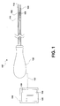
- a device 100 comprises a needle 102 having a tubular body with a lumen 104 extending therethrough from a proximal end extending into a handle 120 to a distal end comprising a puncturing tip 106.
- distal refers to a direction away from a user of the device while the term proximal refers to a direction approaching a user of the device.
- the proximal portion of the device 100 remains external to the body and accessible to the user while the distal portion, when in an operative position, extends into the body to a target site from which tissue samples are to be obtained in accordance with the biopsy procedure.
- a shaft 116 of the device 100 and the needle 102 may be rigid or, alternatively, may be longitudinally flexible and axially rigid to allow for the insertion of the shaft 116 and the needle 102 along a tortuous path (e.g., through a body lumen) to a target site within the body.
- the needle 102 may be formed of any suitable biocompatible material known in the art depending on the desired properties of the needle (e.g., rigidity/flexibility, etc.).
- a series of circumferentially aligned beams 108 are formed along at least one longitudinal length of the needle 102.
- two sets of beams 108 are formed on opposite sides A and B (shown in phantom) of the needle 102, as shown in Fig. 2 .
- the beams 108 may be provided over any part of the needle 102 without deviating from the scope of the present invention.
- the beams 108 may be cantilever beams formed, for example, by laser micromachining or micro-stamping the outer surface of the needle 102. Alternatively, a surface micromachining process may be used to deposit or etch beams 108 onto the surface of the needle 102.
- the beams 108 located on opposite sides A and B may also be formed in different configurations, so as to distinguish an orientation of the needle 102 in situ, as those skilled in the art will understand. Specifically, shapes and sizes of the beams 108 on opposite sides A and B may be distinguishably varied from one another so that an orientation of the needle 102 can be determined based on the location of sides A and B in situ. It is preferred, however, to maintain similar resonance requirements on each side A and B so that both sides are locatable at least one predetermined frequency.
- each of the beams 108 may also be varied depending on the type of procedure being performed so that the natural frequency of the beams 108 coincides with the ultrasonic frequency of interest, as those skilled in the art will understand. If a particular procedure requires the targeting of more than one ultrasound frequency (i.e., to overcome excessive noise encountered at a first frequency, etc.), the beams 108 may be formed with different dimensions to accommodate the plurality of frequencies. Such an embodiment will aid in the location of the needle 102 in the body when any of the plurality of target frequencies are employed. Furthermore, in a preferred embodiment, beams 108 of different natural frequencies are evenly distributed along the needle 102, such as, for example, in an alternating pattern.
- the frequencies may include 5 MHz and 7.5 MHz, although any other frequencies may be employed without deviating from the scope of the present invention.
- the beams 108 may have varying geometries including, but not limited to rectangular, square and triangular and may also have varying thickness, widths and heights.
- the beams 108 may also comprise any combination and plurality of holes, cutouts, slots, slits, bends and other surface features (e.g., peaks, valleys, etc.) without deviating from the scope of the present invention.
- the beams 108 function as resonators in the needle, as those skilled in the art will understand.
- the acoustic energy from an ultrasound transducer located external to the body when in an operative configuration causes the beams 108 to resonate, thus providing an ultrasonic image of the needle 102.
- cantilever beams can resonate to any multiple of their fundamental frequency. Altering the geometry of the beams 108 can increase the fundamental frequency. For example, as shown with respect to Fig. 2 , beams 108' can be formed to resemble two adjacent arced pieces lying along a longitudinal length of the needle 102, wherein the adjacent pieces are separated from one another by a distance D 1 . The distance D 1 , along with other dimensional values of the beams 108' is indicative of the resonating frequency thereof. Since the two arced pieces are not joined together at a proximal end, resonance can be increased, as those skilled in the art will understand. It is noted that any configuration of the beams 108 may be employed without deviating from the spirit and scope of the present invention.
- Resonance in the device of the present invention may also be improved by providing a resonating stylet 110 to be used with the needle 102.
- the resonating stylet 110 would not have to be employed in conjunction with the needle 102 comprising the bearns 108. Rather, the resonating stylet 110 may function with any medical device within which the stylet 110 may be received.
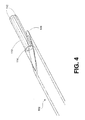
- the stylet 110 is be formed in a cantilever shape, wherein a distal portion of the stylet 110 is formed with two legs 112 spaced from one another and joined to a proximal portion of the stylet at a juncture 114.
- the legs 112 may be formed as a unitary element with the stylet 110 or, alternatively, may be formed separately and attached thereto via a means known in the art such as bonding, welding, etc.
- a distal portion of the stylet 110 serves as a resonator, wherein the dimensions of the legs 112 may dictate the appropriate resonance frequency for the ultrasound.
- the resonance frequency of the cantilever may be approximately 5 MHz to conform to available ultrasound systems, although any other frequency may also be employed without deviating from the scope of the present invention.
- the stylet 110 may also be provided with beams 108 or 108' to further improve imaging or to enable visualization of the stylet 110 under a plurality of frequencies, as explained earlier.
- the beams 108 or 108' may be formed as cut-outs formed in the stylet or may be abutments bonded or otherwise attached to the outer surface of the stylet 110. It is noted that the device of the present invention is not limited to the stylet 110 as depicted but may employ any stylet known in the art. Similarly, the stylet of the present invention may be employed with any device comprising ultrasonic resonators.
- fabrication of the beams 108 of the present invention may be done using the same manufacturing technology used for electrical circuit or micro-electrical mechanical systems ("MEMS"). In this manner, a resonant mechanical system may be produced for one or more frequencies of interest.
- MEMS micro-electrical mechanical systems
- a micro-miniature ultrasonic transducer may be mounted on one or both of the needle 102 or the stylet 110 of the present invention. The micro-miniature ultrasonic transducer may function as a transmitter insertable into the body, with the external ultrasound device functioning as a receiver, as those skilled in the art will understand.
- the needle 102 is received within a lumen 118 extending through a catheter shaft 116, the lumen 118 is sized to slidably receive the needle 102 with a clearance between the needle 102 and an inner wall of the lumen 118.
- an ultrasonic scanner 124 transmits a predetermined ultrasonic frequency.
- a probe 126 generates the designated frequencies to the target area in the body via a path 132. That is, a transducer 128 may be attached to an end of the probe 126. In another embodiment, a separate handheld probe (not shown) may be employed.
- the transducer 128 may be coupled to the probe 126 using a means known in the art and may employ a known material (e.g., water, jelly, etc.) to reduce impedance by the skin.
- the beams 108 may resonate and return the frequencies to the ultrasonic scanner 124.
- a transducer 128 may then convert the received frequencies into electrical pulses that can be processed and transformed into a digital image.
- the ultrasonic scanner 124 then displays the image on a screen 124 visible to a user of the device and operable in real-time. In a preferred embodiment, the image is visible to the user in real time to aid in proper positioning of the catheter shaft 116 in the body.
- actuation of an actuator (not shown) on the handle 120 the needle 102 out of the lumen 118 using a mechanical means known in the art.
- a stylet may be housed in the needle 102 during insertion to prevent unwanted foreign materials from entering the needle, as those skilled in the art will understand.
- a designated procedure such as a biopsy may then be performed.
- the user of the device 100 retracts the needle 102 by, for example, withdrawing the actuator (not shown) in the opposite direction until the puncturing tip 106 of the needle 102 is again fully housed within the catheter shaft 116.
- the design of the handle 120 may take any desired shape as dictated, for example, by ergonomics, etc. and is not limited to the arrangement shown in the embodiment of Fig. 1 .
- the handle 120 is configured to control actuation of the needle 102 via telescoping tubular configuration.
- the catheter shaft 106 may extend proximally from the handle 130 of the device 100 by any desired length, which length may, for example, be selected to conform to the specific requirements for a procedure being performed.
- Fig. 5 depicts a system according to an alternate embodiment of the present invention, wherein the device is formed substantially similarly to the device 100 of Fig. 1 with the exception of a sheath 200 provided over an outer surface of the needle 102.
- the sheath 200 may be provided with resonators 208 distributed thereover in any configuration.
- the resonators 208 may be formed as cutouts on the sheath 200 or abutments bonded or otherwise attached to the sheath 200 and may be configured to enhance the resonance of the beams 108 of the needle 102, as those skilled in the art will understand.
- the sheath (not shown) may be provided over the needle 102 and, once the catheter shaft 116 is positioned in a desired location relative to a target site in the body, the ultrasonic scanner 124 and transducer 128 may be operated as described above to aid in visualization of the needle 102.
- the present invention may be applied to any procedure requiring the insertion of a needle into tissue via a device traversing a tortuous path.
- the present invention has been described with respect to the retrieval of tissue samples, it is submitted that devices for alternate uses such as, for example, needles for injection of fluids to or the withdrawal of fluids from the body may employ to invention without deviating from the spirit and scope of the present invention.
- devices for alternate uses such as, for example, needles for injection of fluids to or the withdrawal of fluids from the body may employ to invention without deviating from the spirit and scope of the present invention.
- these embodiments have been described in an exemplary manner and are not intended to limit the invention which is intended to cover all modifications and variations of this invention that come within the scope of the appended claims and their equivalents.
- the beams of the present invention may be formed separately from the needle and can be subsequently bonded to the needle via a means known in the art.
- ultrasonic resonators of the present invention are not restricted for use with needles and rather, may be employed in any medical device visualized by the use of ultrasound. It is therefore submitted that the embodiments disclosed herein are not limited to limit the scope of the present invention.
Landscapes
- Health & Medical Sciences (AREA)
- Surgery (AREA)
- Life Sciences & Earth Sciences (AREA)
- Biomedical Technology (AREA)
- Nuclear Medicine, Radiotherapy & Molecular Imaging (AREA)
- Engineering & Computer Science (AREA)
- Pathology (AREA)
- Heart & Thoracic Surgery (AREA)
- Medical Informatics (AREA)
- Molecular Biology (AREA)
- Animal Behavior & Ethology (AREA)
- General Health & Medical Sciences (AREA)
- Public Health (AREA)
- Veterinary Medicine (AREA)
- Ultra Sonic Daignosis Equipment (AREA)
Claims (13)
- Medizinische Vorrichtung (100), welche aufweist:eine Kanüle (102), die ausgestaltet ist, in einen Zielort in einem Körper eingeführt zu werden, wobei die Kanüle (102) ein sich durch diese erstreckendes Lumen (104) enthält;zumindest einen Resonator, der sich auf einer Oberfläche der Kanüle (102) befindet, wobei der Resonator im Resonanzzustand ist als Antwort auf eine Ultraschallfrequenz, die auf den Zielort ausgeübt wird, um den Ort der Kanüle (102) in dem Körper anzuzeigen, wobei die Ultraschallfrequenz durch einen Wandler (128) erzeugt wird, der sich außerhalb des Körpers befindet; undeine Vorrichtung (124), die Resonanzfrequenzen in ein Bild umwandelt;gekennzeichnet durchein Stilett (110), das ausgestaltet ist, in das Lumen (104) eingeführt zu werden, einen distalen Bereich von diesem, enthaltend zwei Beine (112), die einen gegenseitigen Abstand aufweisen und an einem proximalen Bereich des Stiletts an einer Verbindungsstelle verbunden sind und als ein Resonanzmerkmal ausgestaltet sind, das im Resonanzzustand ist, wenn es durch Schallwellen betätigt wird.
- Medizinische Vorrichtung (100) nach Anspruch 1, weiterhin aufweisend:einen Handgriff (120), der sich an einem proximalen Ende der Kanüle (102) befindet.
- Medizinische Vorrichtung (100) nach Anspruch 1, bei der der zumindest eine Resonator als ein Auslegerbalken (108) ausgebildet ist.
- Medizinische Vorrichtung (100) nach Anspruch 1, bei der der zumindest eine Resonator als einer aus einem Ausschnitt und einem Widerlager auf einer äußeren Oberfläche der Kanüle (102) gebildet ist.
- Medizinische Vorrichtung (100) nach Anspruch 1, bei der der zumindest eine Resonator in eine äußere Oberfläche der Kanüle (102) geätzt ist.
- Medizinische Vorrichtung (100) nach Anspruch 1, bei der der zumindest eine Resonator über eines von Lasermikrobearbeiten, Mikrostanzen, MEMS und Oberflächenbearbeiten gebildet ist.
- Medizinische Vorrichtung (100) nach Anspruch 6, bei der der zumindest eine Resonator mit der Kanüle (102) verbunden ist.
- Medizinische Vorrichtung (100) nach Anspruch 1, bei der der zumindest eine Resonator so bemessen ist, dass er bei zumindest einer vorbestimmten Frequenz in Resonanz ist.
- Medizinische Vorrichtung (100) nach Anspruch 1, bei der der zumindest eine Resonator als ein Ausleger gebildet ist.
- Medizinische Vorrichtung (100) nach Anspruch 1, bei der das Stilett (110) zumindest einen weiteren Resonator enthält, der sich auf einer Oberfläche des Stiletts (110) befindet.
- Medizinische Vorrichtung (100) nach Anspruch 1, bei der ein Resonator mit einer äußeren Wand des Stiletts (110) verbunden ist.
- Medizinische Vorrichtung (100) nach Anspruch 1, bei der mehrere Resonatoren auf der Kanüle (102) gebildet sind.
- Medizinische Vorrichtung (100) nach Anspruch 12, bei der die Resonatoren entlang einer Längsachse des Lumens (104) ausgerichtet sind.
Applications Claiming Priority (2)
| Application Number | Priority Date | Filing Date | Title |
|---|---|---|---|
| US24545409P | 2009-09-24 | 2009-09-24 | |
| PCT/US2010/049081 WO2011037813A1 (en) | 2009-09-24 | 2010-09-16 | Echogenic needle mechanism |
Publications (2)
| Publication Number | Publication Date |
|---|---|
| EP2470103A1 EP2470103A1 (de) | 2012-07-04 |
| EP2470103B1 true EP2470103B1 (de) | 2014-01-01 |
Family
ID=43014359
Family Applications (1)
| Application Number | Title | Priority Date | Filing Date |
|---|---|---|---|
| EP10757899.9A Active EP2470103B1 (de) | 2009-09-24 | 2010-09-16 | Echogener nadelmechanismus |
Country Status (3)
| Country | Link |
|---|---|
| US (1) | US8369935B2 (de) |
| EP (1) | EP2470103B1 (de) |
| WO (1) | WO2011037813A1 (de) |
Families Citing this family (12)
| Publication number | Priority date | Publication date | Assignee | Title |
|---|---|---|---|---|
| US9011511B2 (en) * | 2009-02-20 | 2015-04-21 | Boston Scientific Scimed, Inc. | Balloon catheter |
| US8882673B2 (en) * | 2010-02-12 | 2014-11-11 | I-Flow Corporation | Continuous transversus abdominis plane block |
| EP2848202A1 (de) * | 2011-05-06 | 2015-03-18 | W.L. Gore & Associates, Inc. | Echogene Hülse |
| US9622719B2 (en) | 2013-02-26 | 2017-04-18 | Allen Maizes | Color ultrasound needle |
| US9717886B2 (en) | 2013-03-12 | 2017-08-01 | Teleflex Medical Incorporated | Safety clip for a needle |
| US10357635B2 (en) | 2013-03-12 | 2019-07-23 | Teleflex Medical Incorporated | Catheter insertion device |
| US11224724B2 (en) | 2013-03-12 | 2022-01-18 | Teleflex Medical Incorporated | Catheter insertion device |
| US9572553B2 (en) | 2013-06-12 | 2017-02-21 | Bradshaw Medical, Inc. | Cannulated medical instrument handle with a removable insert |
| CN107019547B (zh) * | 2017-03-10 | 2019-05-10 | 上海市第十人民医院 | 适用于半月板缝合的穿刺定位系统 |
| CA3059619C (en) | 2017-04-13 | 2022-12-06 | Teleflex Medical Incorporated | Catheter insertion device |
| US10561407B2 (en) | 2017-05-05 | 2020-02-18 | Hoya Corporation | Apparatuses and methods for endoscopic tool joints |
| FR3113233B1 (fr) * | 2020-08-06 | 2023-08-11 | Marc Lenfant | Complexe sonde de derivation ventriculaire externe et stylet echographique pour une pose sous guidage par imagerie continue |
Family Cites Families (8)
| Publication number | Priority date | Publication date | Assignee | Title |
|---|---|---|---|---|
| US4977897A (en) * | 1988-08-17 | 1990-12-18 | Robert Hurwitz | Amniocentesis needle with improved sonographic visibility |
| US5490521A (en) * | 1993-08-31 | 1996-02-13 | Medtronic, Inc. | Ultrasound biopsy needle |
| US6513527B1 (en) * | 2000-06-13 | 2003-02-04 | University Of Mississippi Medical Center | Bibronchial double lumen tube |
| US20070179508A1 (en) * | 2005-12-12 | 2007-08-02 | Cook Critical Care Incorporated | Hyperechoic stimulating block needle |
| KR101113468B1 (ko) | 2006-08-01 | 2012-04-17 | 베리지 (싱가포르) 피티이. 엘티디. | 비동기식 시그마 델타 디지털-아날로그 변환기, 측정 장치, 변환 방법 및 컴퓨터 판독가능 매체 |
| WO2008148165A1 (en) * | 2007-06-06 | 2008-12-11 | Swinburne University Of Technology | Echogenic medical device |
| US7733254B2 (en) | 2007-06-28 | 2010-06-08 | Slicex, Inc. | Sample and hold circuit for a current mode pipelined analog-to-digital converter |
| GB0722406D0 (en) * | 2007-11-15 | 2007-12-27 | Smiths Group Plc | Medico-surgical assemblies and methods |
-
2010
- 2010-09-16 EP EP10757899.9A patent/EP2470103B1/de active Active
- 2010-09-16 US US12/883,379 patent/US8369935B2/en active Active
- 2010-09-16 WO PCT/US2010/049081 patent/WO2011037813A1/en not_active Ceased
Also Published As
| Publication number | Publication date |
|---|---|
| US8369935B2 (en) | 2013-02-05 |
| US20110071386A1 (en) | 2011-03-24 |
| EP2470103A1 (de) | 2012-07-04 |
| WO2011037813A1 (en) | 2011-03-31 |
Similar Documents
| Publication | Publication Date | Title |
|---|---|---|
| EP2470103B1 (de) | Echogener nadelmechanismus | |
| JP6118334B2 (ja) | 閉塞管を可視化するための装置、システムおよび方法 | |
| US11090080B2 (en) | Steerable endoluminal punch with introducer | |
| AU2002312086B2 (en) | Guiding ultrasound end effector for medical treatment | |
| EP2164401B1 (de) | Vorrichtung für geführte penetration bei chronischer totaler okklusion | |
| US6423002B1 (en) | Intra-operative diagnostic ultrasound multiple-array transducer probe and optional surgical tool | |
| AU695163B2 (en) | Medical instrument with improved ultrasonic visibility | |
| US5048530A (en) | Method of using an amniocentesis needle with improved sonographic visibility | |
| US20190142373A1 (en) | Image guided catheters and methods of use | |
| US20080221448A1 (en) | Image-guided delivery of therapeutic tools duing minimally invasive surgeries and interventions | |
| AU2002312086A1 (en) | Guiding ultrasound end effector for medical treatment | |
| EP1858417A1 (de) | Echogene marker auf medizinischen gi-vorrichtungen | |
| JPWO2017013813A1 (ja) | 超音波処置具及び超音波処置アッセンブリ | |
| WO2016047202A1 (ja) | 内視鏡用穿刺針 | |
| JP3641427B2 (ja) | 内視鏡下外科手術用超音波探触子 | |
| JPH0747027B2 (ja) | 超音波内視鏡 | |
| JPH0440652Y2 (de) | ||
| US11633176B2 (en) | Positioning devices, methods, and systems | |
| EP4586933A1 (de) | Abbildungssystem mit auf das sichtfeld ausgerichteter nadel |
Legal Events
| Date | Code | Title | Description |
|---|---|---|---|
| PUAI | Public reference made under article 153(3) epc to a published international application that has entered the european phase |
Free format text: ORIGINAL CODE: 0009012 |
|
| 17P | Request for examination filed |
Effective date: 20120314 |
|
| AK | Designated contracting states |
Kind code of ref document: A1 Designated state(s): AL AT BE BG CH CY CZ DE DK EE ES FI FR GB GR HR HU IE IS IT LI LT LU LV MC MK MT NL NO PL PT RO SE SI SK SM TR |
|
| DAX | Request for extension of the european patent (deleted) | ||
| GRAP | Despatch of communication of intention to grant a patent |
Free format text: ORIGINAL CODE: EPIDOSNIGR1 |
|
| INTG | Intention to grant announced |
Effective date: 20130715 |
|
| GRAS | Grant fee paid |
Free format text: ORIGINAL CODE: EPIDOSNIGR3 |
|
| GRAA | (expected) grant |
Free format text: ORIGINAL CODE: 0009210 |
|
| AK | Designated contracting states |
Kind code of ref document: B1 Designated state(s): AL AT BE BG CH CY CZ DE DK EE ES FI FR GB GR HR HU IE IS IT LI LT LU LV MC MK MT NL NO PL PT RO SE SI SK SM TR |
|
| REG | Reference to a national code |
Ref country code: GB Ref legal event code: FG4D |
|
| REG | Reference to a national code |
Ref country code: CH Ref legal event code: EP |
|
| REG | Reference to a national code |
Ref country code: IE Ref legal event code: FG4D |
|
| REG | Reference to a national code |
Ref country code: AT Ref legal event code: REF Ref document number: 647248 Country of ref document: AT Kind code of ref document: T Effective date: 20140215 |
|
| REG | Reference to a national code |
Ref country code: DE Ref legal event code: R096 Ref document number: 602010012862 Country of ref document: DE Effective date: 20140220 |
|
| REG | Reference to a national code |
Ref country code: NL Ref legal event code: VDEP Effective date: 20140101 |
|
| REG | Reference to a national code |
Ref country code: AT Ref legal event code: MK05 Ref document number: 647248 Country of ref document: AT Kind code of ref document: T Effective date: 20140101 |
|
| REG | Reference to a national code |
Ref country code: LT Ref legal event code: MG4D |
|
| PG25 | Lapsed in a contracting state [announced via postgrant information from national office to epo] |
Ref country code: LT Free format text: LAPSE BECAUSE OF FAILURE TO SUBMIT A TRANSLATION OF THE DESCRIPTION OR TO PAY THE FEE WITHIN THE PRESCRIBED TIME-LIMIT Effective date: 20140101 Ref country code: IS Free format text: LAPSE BECAUSE OF FAILURE TO SUBMIT A TRANSLATION OF THE DESCRIPTION OR TO PAY THE FEE WITHIN THE PRESCRIBED TIME-LIMIT Effective date: 20140501 |
|
| PG25 | Lapsed in a contracting state [announced via postgrant information from national office to epo] |
Ref country code: FI Free format text: LAPSE BECAUSE OF FAILURE TO SUBMIT A TRANSLATION OF THE DESCRIPTION OR TO PAY THE FEE WITHIN THE PRESCRIBED TIME-LIMIT Effective date: 20140101 Ref country code: AT Free format text: LAPSE BECAUSE OF FAILURE TO SUBMIT A TRANSLATION OF THE DESCRIPTION OR TO PAY THE FEE WITHIN THE PRESCRIBED TIME-LIMIT Effective date: 20140101 Ref country code: SE Free format text: LAPSE BECAUSE OF FAILURE TO SUBMIT A TRANSLATION OF THE DESCRIPTION OR TO PAY THE FEE WITHIN THE PRESCRIBED TIME-LIMIT Effective date: 20140101 Ref country code: NL Free format text: LAPSE BECAUSE OF FAILURE TO SUBMIT A TRANSLATION OF THE DESCRIPTION OR TO PAY THE FEE WITHIN THE PRESCRIBED TIME-LIMIT Effective date: 20140101 Ref country code: PT Free format text: LAPSE BECAUSE OF FAILURE TO SUBMIT A TRANSLATION OF THE DESCRIPTION OR TO PAY THE FEE WITHIN THE PRESCRIBED TIME-LIMIT Effective date: 20140502 Ref country code: ES Free format text: LAPSE BECAUSE OF FAILURE TO SUBMIT A TRANSLATION OF THE DESCRIPTION OR TO PAY THE FEE WITHIN THE PRESCRIBED TIME-LIMIT Effective date: 20140101 Ref country code: CY Free format text: LAPSE BECAUSE OF FAILURE TO SUBMIT A TRANSLATION OF THE DESCRIPTION OR TO PAY THE FEE WITHIN THE PRESCRIBED TIME-LIMIT Effective date: 20140101 |
|
| PG25 | Lapsed in a contracting state [announced via postgrant information from national office to epo] |
Ref country code: LV Free format text: LAPSE BECAUSE OF FAILURE TO SUBMIT A TRANSLATION OF THE DESCRIPTION OR TO PAY THE FEE WITHIN THE PRESCRIBED TIME-LIMIT Effective date: 20140101 Ref country code: BE Free format text: LAPSE BECAUSE OF FAILURE TO SUBMIT A TRANSLATION OF THE DESCRIPTION OR TO PAY THE FEE WITHIN THE PRESCRIBED TIME-LIMIT Effective date: 20140101 Ref country code: HR Free format text: LAPSE BECAUSE OF FAILURE TO SUBMIT A TRANSLATION OF THE DESCRIPTION OR TO PAY THE FEE WITHIN THE PRESCRIBED TIME-LIMIT Effective date: 20140101 |
|
| REG | Reference to a national code |
Ref country code: DE Ref legal event code: R097 Ref document number: 602010012862 Country of ref document: DE |
|
| PG25 | Lapsed in a contracting state [announced via postgrant information from national office to epo] |
Ref country code: DK Free format text: LAPSE BECAUSE OF FAILURE TO SUBMIT A TRANSLATION OF THE DESCRIPTION OR TO PAY THE FEE WITHIN THE PRESCRIBED TIME-LIMIT Effective date: 20140101 Ref country code: EE Free format text: LAPSE BECAUSE OF FAILURE TO SUBMIT A TRANSLATION OF THE DESCRIPTION OR TO PAY THE FEE WITHIN THE PRESCRIBED TIME-LIMIT Effective date: 20140101 Ref country code: RO Free format text: LAPSE BECAUSE OF FAILURE TO SUBMIT A TRANSLATION OF THE DESCRIPTION OR TO PAY THE FEE WITHIN THE PRESCRIBED TIME-LIMIT Effective date: 20140101 Ref country code: CZ Free format text: LAPSE BECAUSE OF FAILURE TO SUBMIT A TRANSLATION OF THE DESCRIPTION OR TO PAY THE FEE WITHIN THE PRESCRIBED TIME-LIMIT Effective date: 20140101 |
|
| PLBE | No opposition filed within time limit |
Free format text: ORIGINAL CODE: 0009261 |
|
| STAA | Information on the status of an ep patent application or granted ep patent |
Free format text: STATUS: NO OPPOSITION FILED WITHIN TIME LIMIT |
|
| PG25 | Lapsed in a contracting state [announced via postgrant information from national office to epo] |
Ref country code: SK Free format text: LAPSE BECAUSE OF FAILURE TO SUBMIT A TRANSLATION OF THE DESCRIPTION OR TO PAY THE FEE WITHIN THE PRESCRIBED TIME-LIMIT Effective date: 20140101 Ref country code: PL Free format text: LAPSE BECAUSE OF FAILURE TO SUBMIT A TRANSLATION OF THE DESCRIPTION OR TO PAY THE FEE WITHIN THE PRESCRIBED TIME-LIMIT Effective date: 20140101 |
|
| 26N | No opposition filed |
Effective date: 20141002 |
|
| REG | Reference to a national code |
Ref country code: DE Ref legal event code: R097 Ref document number: 602010012862 Country of ref document: DE Effective date: 20141002 |
|
| PG25 | Lapsed in a contracting state [announced via postgrant information from national office to epo] |
Ref country code: LU Free format text: LAPSE BECAUSE OF FAILURE TO SUBMIT A TRANSLATION OF THE DESCRIPTION OR TO PAY THE FEE WITHIN THE PRESCRIBED TIME-LIMIT Effective date: 20140916 Ref country code: MC Free format text: LAPSE BECAUSE OF FAILURE TO SUBMIT A TRANSLATION OF THE DESCRIPTION OR TO PAY THE FEE WITHIN THE PRESCRIBED TIME-LIMIT Effective date: 20140101 |
|
| REG | Reference to a national code |
Ref country code: CH Ref legal event code: PL |
|
| PG25 | Lapsed in a contracting state [announced via postgrant information from national office to epo] |
Ref country code: SI Free format text: LAPSE BECAUSE OF FAILURE TO SUBMIT A TRANSLATION OF THE DESCRIPTION OR TO PAY THE FEE WITHIN THE PRESCRIBED TIME-LIMIT Effective date: 20140101 |
|
| REG | Reference to a national code |
Ref country code: FR Ref legal event code: ST Effective date: 20150529 |
|
| PG25 | Lapsed in a contracting state [announced via postgrant information from national office to epo] |
Ref country code: CH Free format text: LAPSE BECAUSE OF NON-PAYMENT OF DUE FEES Effective date: 20140930 Ref country code: LI Free format text: LAPSE BECAUSE OF NON-PAYMENT OF DUE FEES Effective date: 20140930 |
|
| PG25 | Lapsed in a contracting state [announced via postgrant information from national office to epo] |
Ref country code: FR Free format text: LAPSE BECAUSE OF NON-PAYMENT OF DUE FEES Effective date: 20140930 |
|
| PG25 | Lapsed in a contracting state [announced via postgrant information from national office to epo] |
Ref country code: SM Free format text: LAPSE BECAUSE OF FAILURE TO SUBMIT A TRANSLATION OF THE DESCRIPTION OR TO PAY THE FEE WITHIN THE PRESCRIBED TIME-LIMIT Effective date: 20140101 Ref country code: NO Free format text: LAPSE BECAUSE OF FAILURE TO SUBMIT A TRANSLATION OF THE DESCRIPTION OR TO PAY THE FEE WITHIN THE PRESCRIBED TIME-LIMIT Effective date: 20140401 |
|
| PG25 | Lapsed in a contracting state [announced via postgrant information from national office to epo] |
Ref country code: BG Free format text: LAPSE BECAUSE OF FAILURE TO SUBMIT A TRANSLATION OF THE DESCRIPTION OR TO PAY THE FEE WITHIN THE PRESCRIBED TIME-LIMIT Effective date: 20140101 Ref country code: MT Free format text: LAPSE BECAUSE OF FAILURE TO SUBMIT A TRANSLATION OF THE DESCRIPTION OR TO PAY THE FEE WITHIN THE PRESCRIBED TIME-LIMIT Effective date: 20140101 Ref country code: IT Free format text: LAPSE BECAUSE OF FAILURE TO SUBMIT A TRANSLATION OF THE DESCRIPTION OR TO PAY THE FEE WITHIN THE PRESCRIBED TIME-LIMIT Effective date: 20140101 Ref country code: GR Free format text: LAPSE BECAUSE OF FAILURE TO SUBMIT A TRANSLATION OF THE DESCRIPTION OR TO PAY THE FEE WITHIN THE PRESCRIBED TIME-LIMIT Effective date: 20140402 |
|
| PG25 | Lapsed in a contracting state [announced via postgrant information from national office to epo] |
Ref country code: HU Free format text: LAPSE BECAUSE OF FAILURE TO SUBMIT A TRANSLATION OF THE DESCRIPTION OR TO PAY THE FEE WITHIN THE PRESCRIBED TIME-LIMIT; INVALID AB INITIO Effective date: 20100916 Ref country code: TR Free format text: LAPSE BECAUSE OF FAILURE TO SUBMIT A TRANSLATION OF THE DESCRIPTION OR TO PAY THE FEE WITHIN THE PRESCRIBED TIME-LIMIT Effective date: 20140101 |
|
| PG25 | Lapsed in a contracting state [announced via postgrant information from national office to epo] |
Ref country code: MK Free format text: LAPSE BECAUSE OF FAILURE TO SUBMIT A TRANSLATION OF THE DESCRIPTION OR TO PAY THE FEE WITHIN THE PRESCRIBED TIME-LIMIT Effective date: 20140101 |
|
| PG25 | Lapsed in a contracting state [announced via postgrant information from national office to epo] |
Ref country code: AL Free format text: LAPSE BECAUSE OF FAILURE TO SUBMIT A TRANSLATION OF THE DESCRIPTION OR TO PAY THE FEE WITHIN THE PRESCRIBED TIME-LIMIT Effective date: 20140101 |
|
| PGFP | Annual fee paid to national office [announced via postgrant information from national office to epo] |
Ref country code: GB Payment date: 20240822 Year of fee payment: 15 |
|
| PGFP | Annual fee paid to national office [announced via postgrant information from national office to epo] |
Ref country code: DE Payment date: 20250820 Year of fee payment: 16 |
|
| PGFP | Annual fee paid to national office [announced via postgrant information from national office to epo] |
Ref country code: IE Payment date: 20250822 Year of fee payment: 16 |