EP2469975B1 - Contrôle de l'efficacité de la source de micro-ondes dans un appareil de chauffage à micro-ondes - Google Patents
Contrôle de l'efficacité de la source de micro-ondes dans un appareil de chauffage à micro-ondes Download PDFInfo
- Publication number
- EP2469975B1 EP2469975B1 EP10196108.4A EP10196108A EP2469975B1 EP 2469975 B1 EP2469975 B1 EP 2469975B1 EP 10196108 A EP10196108 A EP 10196108A EP 2469975 B1 EP2469975 B1 EP 2469975B1
- Authority
- EP
- European Patent Office
- Prior art keywords
- microwave source
- transmission line
- microwave
- microwaves
- impedance
- Prior art date
- Legal status (The legal status is an assumption and is not a legal conclusion. Google has not performed a legal analysis and makes no representation as to the accuracy of the status listed.)
- Active
Links
- 238000010438 heat treatment Methods 0.000 title claims description 64
- 230000005540 biological transmission Effects 0.000 claims description 118
- 238000000034 method Methods 0.000 claims description 22
- 230000008859 change Effects 0.000 claims description 12
- 230000003247 decreasing effect Effects 0.000 claims description 9
- 230000035611 feeding Effects 0.000 description 20
- 238000005259 measurement Methods 0.000 description 10
- 230000006870 function Effects 0.000 description 9
- 230000001276 controlling effect Effects 0.000 description 5
- XLYOFNOQVPJJNP-UHFFFAOYSA-N water Substances O XLYOFNOQVPJJNP-UHFFFAOYSA-N 0.000 description 5
- 230000033228 biological regulation Effects 0.000 description 4
- 239000000919 ceramic Substances 0.000 description 3
- 230000008878 coupling Effects 0.000 description 3
- 238000010168 coupling process Methods 0.000 description 3
- 238000005859 coupling reaction Methods 0.000 description 3
- 230000001419 dependent effect Effects 0.000 description 3
- 238000006073 displacement reaction Methods 0.000 description 3
- 230000010355 oscillation Effects 0.000 description 3
- 238000010586 diagram Methods 0.000 description 2
- 238000005265 energy consumption Methods 0.000 description 2
- 230000008571 general function Effects 0.000 description 2
- 239000002184 metal Substances 0.000 description 2
- 230000001105 regulatory effect Effects 0.000 description 2
- 230000004075 alteration Effects 0.000 description 1
- 238000013461 design Methods 0.000 description 1
- 230000006866 deterioration Effects 0.000 description 1
- 230000000694 effects Effects 0.000 description 1
- 230000006872 improvement Effects 0.000 description 1
- 238000012986 modification Methods 0.000 description 1
- 230000004048 modification Effects 0.000 description 1
- 238000012544 monitoring process Methods 0.000 description 1
- 238000005457 optimization Methods 0.000 description 1
- 230000035515 penetration Effects 0.000 description 1
- 238000012545 processing Methods 0.000 description 1
- 230000005855 radiation Effects 0.000 description 1
- 239000000523 sample Substances 0.000 description 1
- 239000004065 semiconductor Substances 0.000 description 1
- 239000007787 solid Substances 0.000 description 1
- 230000009466 transformation Effects 0.000 description 1
Images

Classifications
-
- H—ELECTRICITY
- H05—ELECTRIC TECHNIQUES NOT OTHERWISE PROVIDED FOR
- H05B—ELECTRIC HEATING; ELECTRIC LIGHT SOURCES NOT OTHERWISE PROVIDED FOR; CIRCUIT ARRANGEMENTS FOR ELECTRIC LIGHT SOURCES, IN GENERAL
- H05B6/00—Heating by electric, magnetic or electromagnetic fields
- H05B6/64—Heating using microwaves
- H05B6/70—Feed lines
- H05B6/705—Feed lines using microwave tuning
-
- H—ELECTRICITY
- H05—ELECTRIC TECHNIQUES NOT OTHERWISE PROVIDED FOR
- H05B—ELECTRIC HEATING; ELECTRIC LIGHT SOURCES NOT OTHERWISE PROVIDED FOR; CIRCUIT ARRANGEMENTS FOR ELECTRIC LIGHT SOURCES, IN GENERAL
- H05B6/00—Heating by electric, magnetic or electromagnetic fields
- H05B6/64—Heating using microwaves
- H05B6/66—Circuits
- H05B6/68—Circuits for monitoring or control
- H05B6/688—Circuits for monitoring or control for thawing
-
- Y—GENERAL TAGGING OF NEW TECHNOLOGICAL DEVELOPMENTS; GENERAL TAGGING OF CROSS-SECTIONAL TECHNOLOGIES SPANNING OVER SEVERAL SECTIONS OF THE IPC; TECHNICAL SUBJECTS COVERED BY FORMER USPC CROSS-REFERENCE ART COLLECTIONS [XRACs] AND DIGESTS
- Y02—TECHNOLOGIES OR APPLICATIONS FOR MITIGATION OR ADAPTATION AGAINST CLIMATE CHANGE
- Y02B—CLIMATE CHANGE MITIGATION TECHNOLOGIES RELATED TO BUILDINGS, e.g. HOUSING, HOUSE APPLIANCES OR RELATED END-USER APPLICATIONS
- Y02B40/00—Technologies aiming at improving the efficiency of home appliances, e.g. induction cooking or efficient technologies for refrigerators, freezers or dish washers
Definitions
- the present invention relates to the field of microwave heating, and in particular to a microwave heating apparatus for heating a load by means of microwaves.
- the art of microwave heating involves feeding of microwave energy into a cavity.
- Some of these aspects may be related to the heating itself wherein it is generally desired to obtain a uniform heating of the food at the same time as a maximum amount of available microwave power is absorbed in the food (to achieve a satisfactory degree of heating efficiency).
- various types of power regulation of the microwave source have been suggested in prior art microwave ovens to improve efficiency.
- a traditional microwave oven equipped with a regular high-voltage transformer for supplying a magnetron power regulation of the magnetron is often accomplished via the use of duty-cycle operation, wherein the magnetron is alternatively turned on and off during periods as defined by the duty-cycle.
- the magnetron is always operated at full power (usually a fixed large average anode current) and the average power of microwaves supplied to a cavity of the microwave oven is regulated by feeding microwaves using a certain percentage of a predefined time base during which the magnetron is oscillating.
- power regulation can be accomplished by supplying the magnetron with intermediate average anode currents, i.e.
- the magnetron is not necessarily operated at full power and there is no need of a duty-cycle.
- the microwave ovens are often designed and optimized for heating of a standard 1000 g water load while the magnetron is at full power (normally 1000 W).
- prior art microwave ovens still suffer from a reduced overall efficiency if the load differs from the 1000 g water load or, if for a 1000 g water load, the oven (in particular provided with an inverter) is not operated at a full power level.
- US 2002/027135 discloses a method for operating a microwave heating apparatus according to the preamble of attached claim 1.
- EP 1643641 discloses a high-frequency heating device comprising a solid-state oscillator that generates microwaves, an amplifier, an isolator that is connected to a stage subsequent to the amplifier and blocks reflected microwaves, and antenna that irradiates microwaves toward an object and a metal cavity that traps microwaves irradiated to the object.
- EP 2200402 discloses a microwave oven with a control unit connected to a microwave source and capable of switching the operating frequency of the microwave source using at least two selected resonance frequencies.
- EP 2182774 discloses a microwave oven having a plurality of feeding parts and a control unit controlling microwave radiation from the plurality of feedings parts in order to control an electromagnetic wave distribution in the heating chamber.
- An object of the present invention is to wholly or partly overcome the above disadvantages and drawbacks of the prior art and to provide an improved alternative to the above technique.
- a method of operating a microwave heating apparatus comprising a microwave source adapted to feed microwaves to a cavity via a transmission line.
- the method comprises the steps of measuring the power of microwaves transmitted from the microwave source to the cavity and receiving operational data indicative of the power supplied to the microwave source.
- the impedance of the transmission line and/or the impedance matching between the microwave source and the transmission line is then adjusted based on the measured power of the transmitted microwaves and the received operational data in order to control the efficiency of the microwave source.
- a microwave heating apparatus comprises a microwave source for generating microwaves, a transmission line for transmitting the generated microwaves from the microwave source to a cavity, measuring means for measuring the power of microwaves transmitted from the microwave source and receiving means for receiving operational data indicative of the power supplied to the microwave source.
- the microwave heating apparatus further comprises a control unit adapted to adjust the impedance of the transmission line and/or the impedance matching between the microwave source and the transmission line based on the measured power of the transmitted microwaves and the received operational data in order to control the efficiency of the microwave source.
- the present invention makes use of an understanding that the impedance of the transmission line and/or the impedance matching between the microwave source and the transmission line may be adjusted in order to control the efficiency of the microwave source.
- the efficiency of the microwave source may be evaluated or determined based on measurement, or monitoring, of the power level of the microwaves transmitted (in the transmission line) from the microwave source to the cavity and based on operational data indicative of the power supplied to the microwave source.
- the efficiency of the microwave source may then be controlled by adjusting the impedance matching between the microwave source and the transmission line and/or the impedance of the transmission line via which the microwaves are transmitted from the microwave source to the cavity.
- the impedance of the transmission line and/or the impedance matching between the microwave source and the transmission line may be adjusted such that the power level of the microwaves transmitted from the microwave source to the cavity is increased, thereby increasing the efficiency of the microwave source (i.e. operating the magnetron, if the microwave source is a magnetron, in the so-called sink phase).
- the impedance of the transmission line and/or the impedance matching between the microwave source and the transmission line may be adjusted such that the power level of the microwaves transmitted from the microwave source to the cavity is decreased, thereby decreasing the efficiency of the microwave source (i.e. operating the magnetron, if the microwave source is a magnetron, in anti-sink phase).
- the present invention is thus advantageous in that it provides a microwave heating apparatus with improved control of the microwave source efficiency. Further, an improved control of the microwave source efficiency contributes positively to the overall energy efficiency of the microwave heating apparatus as a whole.
- the present invention is particularly advantageous in that the efficiency of the microwave source may be controlled depending on dynamical changes occurring in the microwave heating apparatus.
- the efficiency of the microwave source is dependent on the impedance of a system defined by the microwave source, the transmission line and the cavity.
- the impedance of such a system is dependent on a number of parameters such as the form, size and phase of a load arranged in the cavity, the form and size of the transmission line and the form and size of the cavity.
- the impedance may vary because of a change in size, form or phase of the load like at a transformation from frozen to thawed (due to the microwave heating).
- the present invention by adjusting the impedance of the transmission line and/or the impedance matching between the microwave source and the transmission line, it is thus possible to control the efficiency of the microwave source while taking into account any changes occurring in the load (change in size/geometry or change in temperature which alters the dielectric data of the load). Similarly, with the present invention, it is possible to account for changes occurring in the microwave source, e.g. a magnetron, such as a change of the anode current or a change in temperature.
- the present invention is also advantageous in that the efficiency of the microwave source, in particular a magnetron (but also for other types of microwave sources), can automatically be kept at a certain level of efficiency, and preferably in the sink phase, during operation of the microwave heating apparatus.
- the efficiency of the microwave source can be controlled during operation by adjusting or tuning the impedance of the transmission line (and/or the impedance matching between the microwave source and the transmission line, also referred to as impedance adjustments in the following) independently of what has influenced the need for an adjustment (in particular an increase) of the efficiency of the microwave source.
- the efficiency of the microwave source may be kept at a high level by dynamic impedance adjustments.
- the present invention is also advantageous in that the microwave heating apparatus can operate at optimal (or at least improved) conditions independently of the load arranged in the cavity (and in particular not only for a standard 1000 g water load).
- the microwave heating apparatus of the present invention is more flexible.
- sink phase operation for the magnetron may be obtained in principle for any kind of load sizes (or weights) and at least for other (smaller) loads than the standard load normally used for design of microwave ovens.
- the efficiency of the microwave source is often not optimal.
- the present invention is advantageous in that it provides a microwave heating apparatus and a method of operating a microwave heating apparatus with reduced energy consumption since the magnetron may be controlled to operate in the sink phase, i.e. at a high efficiency, and an improved overall efficiency of the microwave heating apparatus is obtained.
- the microwave source may be a magnetron such as e.g. a mains voltage transformer powered magnetron or an inverter-powered magnetron.
- the method may further comprise the step of measuring the power of microwaves reflected back towards the microwave source.
- the microwave heating apparatus may further comprise additional measuring means for measuring the power of the reflected microwaves.
- the efficiency of the microwave source may be controlled based on both the power level of the microwaves transmitted from the microwave source to the cavity and the power level of the microwaves reflected back towards the microwave source.
- the power level of the reflected microwaves is generally representative of the amount of microwaves absorbed by the cavity and, in particular, a load arranged in the cavity.
- the present embodiment is thus advantageous in that the impedance of the transmission line and/or the impedance matching between the microwave source and the transmission line may be adjusted with respect to both the efficiency of the microwave source and the heating efficiency of the microwave heating apparatus.
- the additional measuring means may be provided as an additional function of the measuring means adapted to measure the power of the transmitted microwaves or as a separate unit specifically dedicated to the measurement of the power level of the reflected microwaves.
- the measuring means and the additional measuring means may be a directional coupler, i.e. a single entity, adapted to separately measure the power of the transmitted microwaves and the power of the reflected microwaves.
- the impedance of the transmission line and/or the impedance matching between the microwave source and the transmission line may be adjusted by moving, within the transmission line, at least one element of the group including a slug tuner (i.e. a pin projecting into the transmission line), a motor driven slug tuner, a plunger and a motor driven plunger.
- a plunger enables a change of the geometry or length of the transmission line (e.g. via a movable end or wall of the transmission line), thereby adjusting the impedance of the transmission line and, in particular, the impedance matching between the microwave source and the transmission line.
- a plunger may preferably include a quarter-wave choke (or seal).
- the movable element may also be designed to be a matching element adapted to match or mismatch, depending on the desired control, the impedance between the microwave source and the transmission line.
- Such movable elements or matching elements may be impedance transformers that have the capability of introducing a variable shunt susceptance into the transmission line.
- a slug tuner or plunger may e.g. be implemented as a (longitudinally) adjustable or movable piece of metal arranged at a wall of the transmission line or into the transmission line.
- the movable element may be motor-driven such that an automatic impedance adjustment, and thereby an automatic control of the microwave source efficiency, is obtained.
- the movable element may advantageously be arranged in proximity to the magnetron (or an antenna of the microwave source) since its effect on the impedance then becomes even more increased and, in addition, it strongly influences the magnetron-to-waveguide matching.
- a slug tuner may advantageously be arranged at a certain distance (normally in the order of about half to one wavelength of the microwaves) from the microwave source. The desired distance between the slug tuner and the magnetron may be selected to reduce the likelihood for propagation of evanescent modes or higher order modes present locally around the magnetron antenna.
- the movable element maybe arranged at the extremity corresponding to the microwave source.
- this extremity may be replaced, or equipped, with a movable plug (or plunger) having about the same cross section as the waveguide such that if the distance between the movable plug and the microwave source (or antenna of the microwave source) varies, the coupling between the magnetron and the waveguide varies.
- the magnetron's efficiency may be adjusted by moving the plunger, which effectively changes the overall system impedance.
- the impedance of the transmission line and/or the impedance matching between the microwave source and the transmission line may be adjusted such that the efficiency of the microwave source is increased or maximized if the measured power of the reflected microwaves is below a predetermined threshold. Further, the impedance of the transmission line and/or the impedance matching between the microwave source and the transmission line may be adjusted such that the efficiency of the microwave source is decreased or minimized if the measured power of the reflected microwaves is above the predetermined threshold.
- the present embodiment is advantageous in that it provides a safe manner of operating the microwave heating apparatus (and thereby controlling the efficiency of the microwave source) in that, on the one hand, the efficiency of the microwave source may be increased on a condition that the power level of reflected microwaves remains under a predetermined threshold, and, on the other hand, the efficiency of the microwave source may be decreased if the power level of the reflected microwaves is above the predetermined threshold. Indeed, an increase of the efficiency of the microwave source while the power level of the reflected microwaves has reached the predetermined threshold would deteriorate the microwave source as the amount of microwaves reflected back to the microwave source is already too high. Thus, even if the magnetron operates in anti-sink phase, the impedance is advantageously not adjusted to make the magnetron operate in sink phase if the reflection is too high.
- the very large temperature derivative may in fact lead to a crack in the ceramic window (mainly because of the difference in thermal expansion coefficient between the metallic magnetron's antenna and the ceramic window).
- a very high reflection in the sink phase usually results in reduced oscillation stability and/or antenna to waveguide flashover.
- the power level measured for the reflected microwaves may therefore determine how the microwave source is to be controlled and, in particular, whether the efficiency of the microwave source is to be increased.
- the predetermined threshold may be selected with respect to an amount of reflected microwaves that the microwave source of the microwave heating apparatus can withstand.
- the efficiency of the microwave source is increased as long as the power level of the reflected microwaves is below the predetermined threshold. If the power level of the reflected microwaves is above the predetermined threshold, the efficiency of the microwave source (and thereby the amount of microwaves transmitted to the cavity) is decreased, i.e. leaving the sink phase (in case the microwave source was already operated in the sink phase), which is advantageous due to the risk for moding and/or arcing if the reflection is very high (i.e. above the threshold).
- the impedance of the transmission line and/or the impedance matching between the microwave source and the transmission line may be adjusted as a function of the ratio between the measured power of the transmitted microwaves and the power supplied to the microwave source. More specifically, if the microwave source is a magnetron, the operational data is the anode current of the magnetron. In such a case, the impedance of the transmission line and/or the impedance matching between the microwave source and the transmission line may be adjusted as a function of the ratio between the measured power of the transmitted microwaves and the anode current, wherein a high ratio (and in particular the highest ratio) corresponds to a high efficiency of the microwave source (i.e. the sink phase) and a low or lower ratio correspond to a low or lower efficiency (i.e. the anti-sink phase).
- the microwave source may be turned off if the measured power of the reflected microwaves is above a second predetermined threshold or security threshold, which is advantageous in that it further improves the life-time of the microwave source.
- the security threshold is at a level above the above mentioned (first) predetermined threshold such that, if the power level of the reflected microwaves has (suddenly) reached or is above the security threshold, the control unit of the microwave heating apparatus will not attempt to initiate a decrease of the efficiency of the microwave source by impedance adjustment (which may require some time) but, instead, immediately shut down or turn off the microwave source.
- the present embodiment is advantageous both if the magnetron is operated in the anti-sink phase or in the sink phase. In other words, the measured power of the reflected microwaves is preferably monitored even if the system is tuned for sink phase oscillation.
- FIG. 1 there is shown a schematic view of a microwave heating apparatus according to an embodiment of the present invention.
- the microwave heating apparatus 100 comprises a microwave source 110 (e.g. a magnetron), a transmission line 120 and a cavity 130.
- the microwave source 110 is arranged at a first end, or extremity, of the transmission line 120 while the cavity 130 is arranged at a second end, opposite to the first end, of the transmission line 120.
- the microwave source 110 is adapted to generate microwaves, e.g. via an antenna 112, and the transmission line 120 is configured to transmit the generated microwaves from the (antenna 112 of the) microwave source 110 to the cavity 130.
- the transmission line 120 may also be equipped with a movable element, namely a plunger 180, arranged at the extremity of the transmission line 120 which is closest to the microwave source 110.
- the plunger 180 is movable such that its position may vary in the transmission line 120, thereby varying the impedance matching between the microwave source 110 and the transmission line 120.
- the antenna 112 of the microwave source 110 is inserted into the transmission line or waveguide 120 such that its extremity is at a certain position between the waveguideback shorting wall close to the microwave source and the end of the waveguide connecting to the cavity 130, usually at a distance of about 18-26 mm from the back shorting wall.
- the back shorting wall of the waveguide 120 closest to the microwave source is the wall that is preferably used as the plunger wall.
- the plunger 180 acts as the lateral shorting wall of the transmission line 120.
- the transmission line 120 may also be equipped with further movable element such as a post or pin 185 arranged at a wall of the transmission line 120, preferably one of the broadest wall in the case of a rectangular waveguide (wherein the movable element is inserted in the transmission line 120 via a slot for sliding the pin back and forth).
- the slot(s) are also preferably symmetric in order to reduce any potential microwave leakage (some choking might be needed).
- the post 185 extends in the transmission line 120 and is movable such that its displacement can alter the impedance of the transmission line 120. It will be appreciated that both the lateral position of the movable element 185 along a wall of the transmission line 120 and the penetration depth of the movable element 185 in the transmission line 120 may be adjusted.
- the movable elements such as the plunger 180 and the post 185, may be controlled by a control unit 170 via e.g. an intermediate "servo" unit 172.
- the servo-unit 172 may be connected to a motor (not shown) associated with the plunger 180 and another motor (not shown) associated with the post 185 such that the plunger 180 or the post 180 may be automatically moved in accordance with instructions received from the control unit 170.
- the control unit 170 may determine the need of impedance adjustment and the level of impedance adjustment (e.g. a displacement of any one or both of the movable elements 180 and 185) based on the power level of the microwaves transmitted from the microwave source 110 to the cavity 130 and operational data indicative of the power supplied to the microwave source 110.
- the control unit 170 may be connected to a measuring means 140 adapted to measure the power of the transmitted microwaves and a receiving means 150 adapted to receive the operational data.
- the impedance of the transmission line 120 and/or the impedance matching between the microwave source 110 and the transmission line 120 is adjusted in order to control the efficiency of the microwave source 110.
- the control unit 170 is then configured to adjust the impedance of the transmission line 120 and/or the impedance matching between the microwave source 110 and the transmission line 120.
- the control unit 170 is configured to optimize, or at least increase, the efficiency of the microwave source 110.
- the control unit 170 may be configured to adjust the impedance of the transmission line 120 and/or the impedance matching between the microwave source 110 and the transmission line 120 such that the efficiency of the microwave source 110 is increased.
- control unit 170 may send instructions to the servo-unit 172 to displace or move at least one of the movable elements 180 and 185 in the transmission line 120, thereby altering the impedance of the transmission line 120 and/or the magnetron to waveguide matching.
- control unit 170 may also be configured to decrease the efficiency of the microwave source 110.
- the movable elements 180 and 185 may be directly activated.
- the functions of the servo-unit 172 controlling a motor, or indicating an amount of displacement by which a movable element is to be moved may be integrated in the movable element itself. In such a case, a direct connection between the control unit 170 and the movable elements 180 and 185 may be established.
- the microwave heating apparatus 100 may comprise additional measuring means 145 configured to measure the power level of microwaves reflected back towards the microwave source 110.
- the measuring means 140 and the additional measuring means 145 are integrated in a single entity.
- microwaves transmitted to a cavity may be either absorbed by a load arranged in the cavity, absorbed by elements of the cavity (or other objects present in the cavity), or reflected back from the cavity (or feeding port). Indeed, if the coupling to the cavity 130 is not perfect, some microwave power may be reflected, e.g. through a feeding port, back into the transmission line 120 towards the microwave source 110.
- An advantageous, and thus preferred, way to control whether there is a satisfactory coupling to the cavity 130 is by measuring the power that is reflected from a feeding port of the cavity 130.
- the power of the reflected microwaves may be measured at the extremity of the transmission line 120 which is closest to the cavity 130.
- the powers of the reflected microwaves are, at least partly, representative of the amount of microwaves absorbed by the load 138 arranged in the cavity 130.
- the control unit 170 may then be configured to adjust the impedance of the transmission line 120 and/or the impedance matching between the microwave source 110 and the transmission line 120 such that the efficiency of the microwave source 110 is increased or maximized if the power of the reflected microwaves is below a predetermined threshold.
- the measured power level of reflected microwaves represents an amount of microwaves absorbed by the cavity (and thus the load) such that, if the amount of reflected microwaves is below the predetermined threshold, the load impedance is not completely suitable to the transmission line impedance.
- the predetermined threshold may be selected such that it represents an amount of microwaves that is relatively high but, still, that the microwave source 110 can withstand, which is advantageous in that it provides some kind of protection for the microwave source 110, thereby increasing its lifetime.
- control unit 170 may be configured to turn off the microwave source if the power level of the reflected microwaves measured at the additional measuring unit 145 exceeds a second predetermined threshold, namely a security threshold.
- the security threshold may be selected such that it represents an amount of microwaves that is slightly below an amount of microwaves that the microwave source could not withstand, thereby avoiding (or at least limiting the risk of) any serious deterioration of the microwave source 110.
- the impedance of the transmission line 120 and/or the impedance matching between the microwave source 110 and the transmission line 120 may be adjusted as a function of the ratio between the measured power of the transmitted microwaves and the power supplied to the microwave source 110, which ratio is representative of the efficiency of the microwave source 110.
- the impedance of the transmission line 120 and/or the impedance matching between the microwave source 110 and the transmission line 120 may be adjusted as a function of the ratio between the measured power of the transmitted microwaves and the anode current of the magnetron (wherein the anode current is representative of the power supplied to the magnetron 110).
- microwave ovens provided with inverters for controlling the anode current of the magnetron, such information may be directly obtained, normally via the inverter, by the control unit.
- the present invention to microwave ovens not comprising any inverter and for which the anode current may be derived via e.g. an external current meter. Measurements of the anode current in microwave ovens provided with regular high voltage transformers is preferably performed "outside" the tube of the magnetron itself, e.g. in the supply circuit.
- the frequency of the microwaves varies as a function of the anode current (or as a function of a current from some power supply connected to the magnetron).
- the anode current varies (for any reasons such as a change in output power from e.g. 900 W to 400 W)
- the oscillating frequency of the magnetron may vary (also refers to as the pushing factor), which may affect the efficiency of the magnetron.
- the pushing factor i.e.
- a change in oscillating frequency because of a change in the average anode current may make the magnetron operate in anti-sink phase so that a mechanical adjustment of e.g. a plunger is needed or in sink phase such that no impedance adjustment is needed.
- the present invention takes care of the pushing factor in that the need for impedance adjustment is based on the power level of the transmitted microwaves and the anode current.
- the microwave heating apparatus may then be configured to determine whether the impedance of the transmission line and/or the impedance matching between the microwave source and the transmission line needs to be adjusted in order to control the efficiency of the magnetron.
- the efficiency of the magnetron may e.g. be regulated with respect to a preferred (or maximal) value of the ratio between the power level of the transmitted microwaves and the anode current.
- the efficiency of the magnetron may be increased or decreased with respect to a predetermined threshold for the power level of the reflected microwaves.
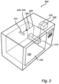
- a microwave heating apparatus 200 e.g. a microwave oven, having features and functions according to another embodiment of the present invention.
- the microwave oven 200 comprises a cavity 230 defined by an enclosing surface.
- One of the side walls of the cavity 230 may be equipped with a door 235 for enabling the introduction of a load, e.g. food, in the cavity 230.
- the cavity 230 may be provided with a feeding port (or antenna) 233 through which microwaves are fed to the cavity 230 of the microwave oven 200.
- the feeding port may for instance be an antenna, such as a patch antenna or a H-loop antenna, or even an aperture in a wall (including sidewalls, the bottom and the ceiling) of the cavity 230.
- feeding port may for instance be an antenna, such as a patch antenna or a H-loop antenna, or even an aperture in a wall (including sidewalls, the bottom and the ceiling) of the cavity 230.
- the microwave oven 200 further comprises a microwave source 210, e.g. a magnetron, connected to the feeding port 233 of the cavity 230 by means of a transmission line or waveguide 220.
- the transmission line 220 may for instance be a coaxial cable.
- the transmission line 220 may comprise a plurality of movable elements 280, such as those described above with reference to Figure 1 , for adjusting the impedance of the transmission line 220 and/or the impedance matching between the microwave source 210 and the transmission line 220.
- the microwave oven 200 comprises a first measuring unit (or measuring means) 240 for obtaining, or being adapted to obtain, a signal representative of the power transmitted from the microwave source 210.
- the microwave oven 200 may also comprise a second measuring unit (or measuring means) 245 for obtaining, or being adapted to obtain, a signal representative of the reflected microwaves from the cavity 230 at the feeding port 233. Both the first and the second measuring means 240 and 245 may be arranged at the feeding port 233.
- the microwave oven 200 comprises a receiving means 250 adapted to receive operational data (i.e. information) indicative of the power supplied to the microwave source 210.
- operational data i.e. information
- the microwave oven 200 comprises a control unit 270 operatively connected to the first measuring unit 240, the second measuring unit 245 and the receiving means 250.
- the result of the measurement performed by the first measuring unit 240, the second measuring unit 245 and the information received by the receiving means 250 are transmitted to the control means or unit 270.
- the control unit 270 is then configured to adjust the impedance of the transmission line 220 and/or the impedance matching between the microwave source 210 and the transmission line 220 based on the measured power of the transmitted microwaves, the received operational data and, optionally, the measured power of the reflected microwaves.
- first measuring unit 240 and the second measuring unit 245 may be integrated as sub-units in the control unit 270.
- the measuring units 240 and 245 may be arranged as separate units connected to the control unit 270.
- the sensing part(s) of the first measuring unit 240 and the second measuring unit 245 may be a probe comprising a field-sensor at its extremity for sensing the energy transmitted to or reflected from the cavity, respectively.
- the first measuring unit 240 and the second measuring unit 245 may be a directional coupler arranged in proximity to the feeding port 233 and in proximity to, or in connection with, the transmission line 220 connecting the microwave source 210 with the feeding port 233.
- the receiving means 250 although it is represented as a separate entity in Figure 2 , may be an integrated part of either one of the microwave source 210 or the control unit 270.
- the respective powers of the transmitted, and optionally the reflected, microwaves may be measured by the measuring units 240 and 245 at various time points during an operation cycle (for instance used for heating a load arranged in the cavity) of the microwave heating apparatus 200 and the impedance of the transmission line 220 adjusted in accordance with any one of the above described embodiments. It is therefore contemplated that the first and second measuring units 240 and 245 may be adapted to, continuously or periodically, monitor the signals representative of the powers of the transmitted and reflected microwaves in order to dynamically (i.e., during an operation cycle) control the efficiency of the microwave source 210.
- the microwave oven 200 may further comprise a clock system (not shown in Figure 1 but in Figure 3 ).
- a microwave heating apparatus e.g. a microwave oven
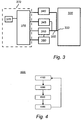
- Figure 3 The general function of a microwave heating apparatus, e.g. a microwave oven, according to an embodiment of the present invention is further illustrated in Figure 3 in the form of a block diagram.
- a microwave generator 310 feed microwaves to a cavity 330 via a transmission line 320 and a feeding port 333.
- the signals representative of the power of the transmitted microwaves are obtained by a first measuring unit 340 and are then transmitted to a control unit 370.
- Operational data indicative of the power supplied to the microwave generator 310 is received by a receiving means 350 and then transmitted to the control unit 370.
- the control unit 370 may comprise a processor or processing means 375 for analyzing the signal obtained from the first measuring means 340 and the operational data received from the receiving means 350.
- the microwave heating apparatus may comprise an additional measuring means 345 for measuring the power of the microwaves reflected back towards the microwave generator 310.
- the signal representative of the power of the reflected microwaves is then transmitted to the control unit 370.
- the control unit 370 is configured to control the efficiency of the microwave generator 310 by adjustment of the impedance in the transmission line 320 and/or the impedance matching between the microwave generator 310 and the transmission line 320.
- control unit 370 may further comprise a clock system 376 for synchronizing the period of measurements and the period during which the impedance is being adjusted.
- the first and second measuring units 340 and 345 and the control unit 370 may be configured to operate in a similar manner as the first measuring means 140 and 240, the second measuring units 145 and 245, and the control units 170 and 270 described above with reference to Figures 1 and 2 , respectively.
- the method comprises the step of measuring 4100 the power of microwaves transmitted from the microwave source to the cavity and the step of receiving 4200 operational data indicative of the power supplied to the microwave source.
- the method comprises also the step of measuring 4300 the power of microwaves reflected back towards the microwave source.
- the method then comprises the step of adjusting 4400 the impedance of the transmission line and/or the impedance matching between the microwave source and the transmission line based on the measured power of the transmitted microwaves and the received operational data in order to control the efficiency of the microwave source.
- the impedance adjustment(s) at step 4400 includes moving of at least one element within the transmission line. Once the movable element has been displaced, the power measurements performed at steps 4100 and 4300 for measuring the power level of the transmitted microwaves and the power level of the reflected microwaves, respectively, may be repeated, as indicated in Figure 4 . In this manner, a continuous regulation of the efficiency of the microwave source is provided.
- the measurements and the adjustment of the impedance are advantageously performed at a sufficient rate such that the magnetron efficiency in principle remains unaffected of changes, e.g. thermal changes, in either the load or the magnetron itself.
- the present invention is applicable for domestic appliances such as a microwave oven using microwaves for heating.
- the present invention is also applicable for larger industrial appliances found in e.g. food operation.
- the present invention is also applicable for vending machines or any other dedicated applicators.
- the microwave ovens 100 and 200 described with reference to Figures 1 and 2 have a rectangular enclosing surface, it will be appreciated that, in the present invention, the cavity of the microwave oven is not limited to such a shape and may, for instance, have a circular cross section.
- steps of the method described with reference to Figure 4 may be performed in another order than that described above, in particular for steps 4100-4300.
- the present invention is not limited to any specific range of frequencies for operation of the microwave heating apparatus.
- the present invention is therefore applicable for any standard microwave sources having mid-band frequencies of 915 MHz, 2450 MHz, 5800 MHz and 22.125 GHz.
- the microwave source may for example be a solid state microwave generator (or semiconductor-based microwave generator) including e.g. a varactor diode (having a voltage-controlled capacitance).
- microwave heating apparatus comprising a single microwave source
- the present invention may also be applied to a microwave heating apparatus comprising a plurality of microwave sources wherein each of the microwave source is associated with a dedicated transmission line and dedicated feeding port such that the power of the microwaves transmitted from each of the microwave sources and, optionally, the power of the microwaves reflected to each one of the microwave sources can be separately monitored (while reducing any crosstalk disturbance).
- the feeding ports may be arranged to provide an orthogonal feeding of the microwaves in the cavity.
Claims (15)
- Procédé de fonctionnement d'un appareil de chauffage à micro-ondes (100) comprenant une source de micro-ondes (110) qui est à même de fournir des micro-ondes à une cavité (130) via une ligne de transmission (120), le procédé comprenant les étapes consistant à :mesurer (4100) la puissance des micro-ondes transmises de la source de micro-ondes à la cavité ; etrecevoir (4200) des données opérationnelles indicatives de la puissance fournie à la source de micro-ondes ; caractérisé en ce qu'il comprend en outre :l'ajustement (4400) de l'impédance de la ligne de transmission et/ou de l'adaptation d'impédance entre la source de micro-ondes et la ligne de transmission sur la base de la puissance mesurée des micro-ondes transmises et des données opérationnelles reçues afin de réguler l'efficacité de la source de micro-ondes.
- Procédé selon la revendication 1, comprenant en outre l'étape de mesure (4300) de la puissance des micro-ondes renvoyées vers la source de micro-ondes.
- Procédé selon la revendication 1 ou 2, dans lequel l'ajustement de l'impédance de la ligne de transmission et/ou de l'adaptation d'impédance entre la source de micro-ondes et la ligne de transmission comprend :le déplacement dans la ligne de transmission d'au moins un élément (180, 185) du groupe comprenant un manchon de réglage, un manchon de réglage entraîné par un moteur, un plongeur et un plongeur entraîné par un moteur ; oule changement de la géométrie ou de la longueur de la ligne de transmission.
- Procédé selon la revendication 2, dans lequel l'impédance de la ligne de transmission et/ou l'adaptation d'impédance entre la source de micro-ondes et la ligne de transmission est ou sont ajustées de sorte que l'efficacité de la source de micro-ondes soit augmentée ou maximisée si la puissance mesurée des micro-ondes réfléchies se situe en dessous d'un seuil prédéterminé et de sorte que l'efficacité de la source de micro-ondes soit réduite ou minimisée si la puissance mesurée des micro-ondes réfléchies se situe au-dessus dudit seuil prédéterminé.
- Procédé selon l'une quelconque des revendications précédentes, dans lequel l'impédance de la ligne de transmission et/ou l'adaptation d'impédance entre la source de micro-ondes et la ligne de transmission est ou sont ajustées en fonction du rapport entre la puissance mesurée des micro-ondes transmises et la puissance fournie à la source de micro-ondes.
- Procédé selon la revendication 2 ou 4, comprenant en outre l'étape de coupure de la source de micro-ondes si la puissance mesurée des micro-ondes réfléchies se situe au-dessus d'un seuil de sécurité.
- Appareil de chauffage à micro-ondes (100) comprenant :une source de micro-ondes (110) pour générer des micro-ondes ;une ligne de transmission (120) pour transmettre les micro-ondes générées de ladite source de micro-ondes à une cavité (130) ;des moyens de mesure (140) pour mesurer la puissance des micro-ondes transmises par la source de micro-ondes ; etdes moyens de réception (150) pour recevoir des données opérationnelles indicatives de la puissance fournie à la source de micro-ondes ; caractérisé en ce qu'il comprend en outre :une unité de commande (170) qui est à même d'ajuster l'impédance de la ligne de transmission et/ou l'adaptation d'impédance entre la source de micro-ondes et la ligne de transmission sur la base de la puissance mesurée des micro-ondes transmises et des données opérationnelles reçues afin de commander l'efficacité de la source de micro-ondes.
- Appareil de chauffage à micro-ondes selon la revendication 7, comprenant en outre des moyens de mesure supplémentaires (145) pour mesurer la puissance des micro-ondes renvoyées vers la source de micro-ondes.
- Appareil de chauffage à micro-ondes selon la revendication 7 ou la revendication 8, dans lequel, pour ajuster l'impédance de la ligne de transmission et/ou l'adaptation d'impédance entre la source de micro-ondes et la ligne de transmission, l'unité de commande est configurée :pour déplacer dans la ligne de transmission un élément (180, 185) qui est au moins l'un du groupe comprenant un manchon de réglage, un manchon de réglage entraîné par un moteur, un plongeur et un plongeur entraîné par un moteur ; oupour changer la géométrie ou la longueur de la ligne de transmission.
- Appareil de chauffage à micro-ondes selon la revendication 9, dans lequel ledit plongeur est aménagé à proximité de ladite source de micro-ondes.
- Appareil de chauffage à micro-ondes selon l'une quelconque des revendications 8 à 10, dans lequel l'unité de commande est configurée pour ajuster l'impédance de la ligne de transmission et/ou l'adaptation d'impédance entre la source de micro-ondes et la ligne de transmission de sorte que l'efficacité de la source de micro-ondes soit augmentée ou maximisée si la puissance mesurée des micro-ondes réfléchies se situe en dessous d'un seuil prédéterminé et de sorte que l'efficacité de la source de micro-ondes soit réduite ou minimisée si la puissance mesurée des micro-ondes réfléchies se situe au-dessus dudit seuil prédéterminé.
- Appareil de chauffage à micro-ondes selon l'une quelconque des revendications 8 à 11, dans lequel l'unité de commande est configurée pour couper la source de micro-ondes si la puissance mesurée des micro-ondes réfléchies se situe au-dessus d'un seuil de sécurité.
- Appareil de chauffage à micro-ondes selon l'une quelconque des revendications 7 à 12, dans lequel l'unité de commande est configurée pour commander l'efficacité de la source de micro-ondes en fonction du rapport entre la puissance mesurée des micro-ondes transmises et la puissance fournie à la source de micro-ondes.
- Appareil de chauffage à micro-ondes selon l'une quelconque des revendications 7 à 13, comprenant un coupleur directionnel qui est à même de mesurer la puissance des micro-ondes transmises et la puissance des micro-ondes réfléchies.
- Appareil de chauffage à micro-ondes selon l'une quelconque des revendications 7 à 14, dans lequel la source de micro-ondes est un magnétron et les données opérationnelles sont le courant anodique du magnétron.
Priority Applications (5)
| Application Number | Priority Date | Filing Date | Title |
|---|---|---|---|
| EP10196108.4A EP2469975B1 (fr) | 2010-12-21 | 2010-12-21 | Contrôle de l'efficacité de la source de micro-ondes dans un appareil de chauffage à micro-ondes |
| PL10196108.4T PL2469975T3 (pl) | 2010-12-21 | 2010-12-21 | Sterowanie wydajnością źródła mikrofalowego w mikrofalowym urządzeniu podgrzewającym |
| US13/331,959 US20120152938A1 (en) | 2010-12-21 | 2011-12-20 | Control of microwave source efficiency in a microwave heating apparatus |
| US15/862,890 US10820383B2 (en) | 2010-12-21 | 2018-01-05 | Control of microwave source efficiency in a microwave heating apparatus |
| US17/077,156 US11765799B2 (en) | 2010-12-21 | 2020-10-22 | Control of microwave source efficiency in a microwave heating apparatus |
Applications Claiming Priority (1)
| Application Number | Priority Date | Filing Date | Title |
|---|---|---|---|
| EP10196108.4A EP2469975B1 (fr) | 2010-12-21 | 2010-12-21 | Contrôle de l'efficacité de la source de micro-ondes dans un appareil de chauffage à micro-ondes |
Publications (2)
| Publication Number | Publication Date |
|---|---|
| EP2469975A1 EP2469975A1 (fr) | 2012-06-27 |
| EP2469975B1 true EP2469975B1 (fr) | 2016-05-11 |
Family
ID=44059016
Family Applications (1)
| Application Number | Title | Priority Date | Filing Date |
|---|---|---|---|
| EP10196108.4A Active EP2469975B1 (fr) | 2010-12-21 | 2010-12-21 | Contrôle de l'efficacité de la source de micro-ondes dans un appareil de chauffage à micro-ondes |
Country Status (3)
| Country | Link |
|---|---|
| US (3) | US20120152938A1 (fr) |
| EP (1) | EP2469975B1 (fr) |
| PL (1) | PL2469975T3 (fr) |
Cited By (1)
| Publication number | Priority date | Publication date | Assignee | Title |
|---|---|---|---|---|
| US10763814B2 (en) | 2016-08-09 | 2020-09-01 | John Bean Technologies Corporation | Radio frequency processing apparatus and method |
Families Citing this family (15)
| Publication number | Priority date | Publication date | Assignee | Title |
|---|---|---|---|---|
| EP2469974B1 (fr) * | 2010-12-21 | 2017-01-25 | Whirlpool Corporation | Procédés pour la commande du refroidissement d'un appareil de chauffage par micro-ondes et appareil correspondant |
| ITRE20130028A1 (it) * | 2013-04-17 | 2014-10-18 | Inermax S R L | Sistema emettitore di microonde |
| CA2942672C (fr) * | 2014-03-20 | 2021-10-26 | Guangdong Midea Kitchen Appliances Manufacturing Co., Ltd. | Structure de connexion et structure de connexion d'entree/de sortie d'un generateur de micro-ondes a semi-conducteur pour un four a micro-ondes, et four a micro-ondes |
| EP2953425B1 (fr) * | 2014-06-03 | 2019-08-21 | Ampleon Netherlands B.V. | Appareil de chauffage à fréquence radio |
| DE102016221447A1 (de) * | 2016-11-02 | 2018-05-03 | BSH Hausgeräte GmbH | Haushalts-Gargerät |
| CN109417840B (zh) * | 2016-11-18 | 2022-04-08 | 惠而浦有限公司 | 具有多个馈送端口的微波炉的波导的rf功率控制系统及其方法 |
| US10390200B2 (en) | 2016-12-19 | 2019-08-20 | Nxp B.V. | Method and system for operating a communications device that communicates via inductive coupling |
| US10721604B2 (en) | 2016-12-19 | 2020-07-21 | Nxp B.V. | Method and system for operating a communications device that communicates via inductive coupling |
| US10382098B2 (en) | 2017-09-25 | 2019-08-13 | Nxp B.V. | Method and system for operating a communications device that communicates via inductive coupling |
| US10720967B2 (en) * | 2017-09-25 | 2020-07-21 | Nxp B.V. | Method and system for operating a communications device that communicates via inductive coupling |
| CN111380332A (zh) * | 2018-12-29 | 2020-07-07 | 中国科学院微电子研究所 | 一种具有功率自适应调节的微波干燥装置 |
| CN110996422B (zh) * | 2019-12-30 | 2022-02-01 | 广东美的厨房电器制造有限公司 | 微波加热组件、微波加热设备和控制方法 |
| WO2022058998A1 (fr) | 2020-09-15 | 2022-03-24 | Goji Limited | Module de puissance rf doté d'un élément rayonnant rf sans connecteur |
| CN114246964A (zh) * | 2020-09-21 | 2022-03-29 | 陕西青朗万城环保科技有限公司 | 一种多模混合腔调节方法及其控制系统 |
| CN112816312A (zh) * | 2020-12-30 | 2021-05-18 | 杭州谱育科技发展有限公司 | 微波消解的调节方法 |
Family Cites Families (15)
| Publication number | Priority date | Publication date | Assignee | Title |
|---|---|---|---|---|
| JPS57192266A (en) * | 1981-05-19 | 1982-11-26 | Toshiba Corp | Plasma surface treating apparatus |
| US4711983A (en) * | 1986-07-07 | 1987-12-08 | Gerling John E | Frequency stabilized microwave power system and method |
| US4866346A (en) * | 1987-06-22 | 1989-09-12 | Applied Science & Technology, Inc. | Microwave plasma generator |
| JPH01297141A (ja) * | 1988-05-25 | 1989-11-30 | Canon Inc | マイクロ波プラズマ処理装置 |
| EP0865065B1 (fr) * | 1997-03-10 | 2003-09-03 | Sumitomo Electric Industries, Ltd. | Elément émitteur d'électrons, procédé de fabrication et dispositif d'électrons |
| US6080270A (en) * | 1997-07-14 | 2000-06-27 | Lam Research Corporation | Compact microwave downstream plasma system |
| US6067475A (en) * | 1998-11-05 | 2000-05-23 | Urologix, Inc. | Microwave energy delivery system including high performance dual directional coupler for precisely measuring forward and reverse microwave power during thermal therapy |
| WO2000052970A1 (fr) * | 1999-03-04 | 2000-09-08 | Mt Systems, Llc | Appareil de chauffage par micro-ondes pour colonnes de chromatographie en phase gazeuse |
| EP1257356B1 (fr) * | 2000-02-25 | 2004-08-18 | Biotage AB | Appareil de chauffage a micro-ondes |
| US7445690B2 (en) * | 2002-10-07 | 2008-11-04 | Tokyo Electron Limited | Plasma processing apparatus |
| JP2006128075A (ja) * | 2004-10-01 | 2006-05-18 | Seiko Epson Corp | 高周波加熱装置、半導体製造装置および光源装置 |
| WO2009011111A1 (fr) * | 2007-07-13 | 2009-01-22 | Panasonic Corporation | Dispositif de chauffage par micro-ondes |
| EP2200402B1 (fr) * | 2008-12-19 | 2011-08-31 | Whirlpool Corporation | Four à micro-ondes commutant entre modes prédéfinis |
| CN102474924B (zh) * | 2009-09-29 | 2013-08-14 | 松下电器产业株式会社 | 高频加热装置以及高频加热方法 |
| EP2677838B1 (fr) * | 2012-06-18 | 2017-12-06 | Whirlpool Corporation | Appareil de chauffage à micro-ondes |
-
2010
- 2010-12-21 PL PL10196108.4T patent/PL2469975T3/pl unknown
- 2010-12-21 EP EP10196108.4A patent/EP2469975B1/fr active Active
-
2011
- 2011-12-20 US US13/331,959 patent/US20120152938A1/en not_active Abandoned
-
2018
- 2018-01-05 US US15/862,890 patent/US10820383B2/en active Active
-
2020
- 2020-10-22 US US17/077,156 patent/US11765799B2/en active Active
Non-Patent Citations (1)
| Title |
|---|
| None * |
Cited By (2)
| Publication number | Priority date | Publication date | Assignee | Title |
|---|---|---|---|---|
| US10763814B2 (en) | 2016-08-09 | 2020-09-01 | John Bean Technologies Corporation | Radio frequency processing apparatus and method |
| US11489507B2 (en) | 2016-08-09 | 2022-11-01 | John Bean Technologies Corporation | Radio frequency processing apparatus and method |
Also Published As
| Publication number | Publication date |
|---|---|
| US20180132311A1 (en) | 2018-05-10 |
| US20210045201A1 (en) | 2021-02-11 |
| PL2469975T3 (pl) | 2016-09-30 |
| US10820383B2 (en) | 2020-10-27 |
| EP2469975A1 (fr) | 2012-06-27 |
| US11765799B2 (en) | 2023-09-19 |
| US20120152938A1 (en) | 2012-06-21 |
Similar Documents
| Publication | Publication Date | Title |
|---|---|---|
| US11765799B2 (en) | Control of microwave source efficiency in a microwave heating apparatus | |
| EP2205043B1 (fr) | Appareil de chauffage par micro-ondes | |
| US9717116B2 (en) | Microwave oven and related method | |
| US2593067A (en) | High-frequency apparatus | |
| EP2677839A1 (fr) | Appareil de chauffage par micro-ondes avec points à alimentation multiple | |
| US11818826B2 (en) | Methods of controlling cooling in a microwave heating apparatus and apparatus thereof | |
| CN111720865B (zh) | 具有再辐射器的rf加热设备 | |
| KR101762163B1 (ko) | 조리기기 | |
| KR101759160B1 (ko) | 조리기기 및 그 동작방법 | |
| KR20120019276A (ko) | 마이크로웨이브를 이용한 조리기기 | |
| KR102134683B1 (ko) | 라디오파 가열 조리기기 | |
| KR101762161B1 (ko) | 조리기기 | |
| KR101731389B1 (ko) | 마이크로웨이브를 이용한 조리기기 | |
| KR101762162B1 (ko) | 조리기기 및 그 제어방법 | |
| KR101748607B1 (ko) | 마이크로웨이브를 이용한 조리기기 | |
| KR101742987B1 (ko) | 마이크로웨이브를 이용한 조리기기 | |
| GB2615765A (en) | Dual-frequency microwave antenna | |
| KR101620447B1 (ko) | 마이크로웨이브를 이용한 조리기기 | |
| KR101811592B1 (ko) | 마이크로웨이브를 이용한 조리기기 | |
| KR20120024044A (ko) | 마이크로웨이브를 이용한 조리기기 | |
| KR20110129722A (ko) | 마이크로웨이브를 이용한 조리기기 및 그 동작방법 |
Legal Events
| Date | Code | Title | Description |
|---|---|---|---|
| AK | Designated contracting states |
Kind code of ref document: A1 Designated state(s): AL AT BE BG CH CY CZ DE DK EE ES FI FR GB GR HR HU IE IS IT LI LT LU LV MC MK MT NL NO PL PT RO RS SE SI SK SM TR |
|
| AX | Request for extension of the european patent |
Extension state: BA ME |
|
| PUAI | Public reference made under article 153(3) epc to a published international application that has entered the european phase |
Free format text: ORIGINAL CODE: 0009012 |
|
| 17P | Request for examination filed |
Effective date: 20121219 |
|
| REG | Reference to a national code |
Ref country code: DE Ref legal event code: R079 Ref document number: 602010033230 Country of ref document: DE Free format text: PREVIOUS MAIN CLASS: H05B0006700000 Ipc: H05B0006680000 |
|
| GRAP | Despatch of communication of intention to grant a patent |
Free format text: ORIGINAL CODE: EPIDOSNIGR1 |
|
| RIC1 | Information provided on ipc code assigned before grant |
Ipc: H05B 6/68 20060101AFI20160114BHEP Ipc: H05B 6/70 20060101ALI20160114BHEP |
|
| INTG | Intention to grant announced |
Effective date: 20160211 |
|
| GRAS | Grant fee paid |
Free format text: ORIGINAL CODE: EPIDOSNIGR3 |
|
| GRAA | (expected) grant |
Free format text: ORIGINAL CODE: 0009210 |
|
| AK | Designated contracting states |
Kind code of ref document: B1 Designated state(s): AL AT BE BG CH CY CZ DE DK EE ES FI FR GB GR HR HU IE IS IT LI LT LU LV MC MK MT NL NO PL PT RO RS SE SI SK SM TR |
|
| REG | Reference to a national code |
Ref country code: GB Ref legal event code: FG4D |
|
| REG | Reference to a national code |
Ref country code: CH Ref legal event code: EP |
|
| REG | Reference to a national code |
Ref country code: AT Ref legal event code: REF Ref document number: 799524 Country of ref document: AT Kind code of ref document: T Effective date: 20160515 |
|
| REG | Reference to a national code |
Ref country code: IE Ref legal event code: FG4D |
|
| REG | Reference to a national code |
Ref country code: DE Ref legal event code: R096 Ref document number: 602010033230 Country of ref document: DE |
|
| REG | Reference to a national code |
Ref country code: LT Ref legal event code: MG4D |
|
| REG | Reference to a national code |
Ref country code: NL Ref legal event code: MP Effective date: 20160511 |
|
| PG25 | Lapsed in a contracting state [announced via postgrant information from national office to epo] |
Ref country code: LT Free format text: LAPSE BECAUSE OF FAILURE TO SUBMIT A TRANSLATION OF THE DESCRIPTION OR TO PAY THE FEE WITHIN THE PRESCRIBED TIME-LIMIT Effective date: 20160511 Ref country code: NL Free format text: LAPSE BECAUSE OF FAILURE TO SUBMIT A TRANSLATION OF THE DESCRIPTION OR TO PAY THE FEE WITHIN THE PRESCRIBED TIME-LIMIT Effective date: 20160511 Ref country code: FI Free format text: LAPSE BECAUSE OF FAILURE TO SUBMIT A TRANSLATION OF THE DESCRIPTION OR TO PAY THE FEE WITHIN THE PRESCRIBED TIME-LIMIT Effective date: 20160511 Ref country code: NO Free format text: LAPSE BECAUSE OF FAILURE TO SUBMIT A TRANSLATION OF THE DESCRIPTION OR TO PAY THE FEE WITHIN THE PRESCRIBED TIME-LIMIT Effective date: 20160811 |
|
| REG | Reference to a national code |
Ref country code: FR Ref legal event code: PLFP Year of fee payment: 7 |
|
| REG | Reference to a national code |
Ref country code: AT Ref legal event code: MK05 Ref document number: 799524 Country of ref document: AT Kind code of ref document: T Effective date: 20160511 |
|
| PG25 | Lapsed in a contracting state [announced via postgrant information from national office to epo] |
Ref country code: ES Free format text: LAPSE BECAUSE OF FAILURE TO SUBMIT A TRANSLATION OF THE DESCRIPTION OR TO PAY THE FEE WITHIN THE PRESCRIBED TIME-LIMIT Effective date: 20160511 Ref country code: HR Free format text: LAPSE BECAUSE OF FAILURE TO SUBMIT A TRANSLATION OF THE DESCRIPTION OR TO PAY THE FEE WITHIN THE PRESCRIBED TIME-LIMIT Effective date: 20160511 Ref country code: RS Free format text: LAPSE BECAUSE OF FAILURE TO SUBMIT A TRANSLATION OF THE DESCRIPTION OR TO PAY THE FEE WITHIN THE PRESCRIBED TIME-LIMIT Effective date: 20160511 Ref country code: LV Free format text: LAPSE BECAUSE OF FAILURE TO SUBMIT A TRANSLATION OF THE DESCRIPTION OR TO PAY THE FEE WITHIN THE PRESCRIBED TIME-LIMIT Effective date: 20160511 Ref country code: GR Free format text: LAPSE BECAUSE OF FAILURE TO SUBMIT A TRANSLATION OF THE DESCRIPTION OR TO PAY THE FEE WITHIN THE PRESCRIBED TIME-LIMIT Effective date: 20160812 Ref country code: SE Free format text: LAPSE BECAUSE OF FAILURE TO SUBMIT A TRANSLATION OF THE DESCRIPTION OR TO PAY THE FEE WITHIN THE PRESCRIBED TIME-LIMIT Effective date: 20160511 Ref country code: PT Free format text: LAPSE BECAUSE OF FAILURE TO SUBMIT A TRANSLATION OF THE DESCRIPTION OR TO PAY THE FEE WITHIN THE PRESCRIBED TIME-LIMIT Effective date: 20160912 |
|
| PG25 | Lapsed in a contracting state [announced via postgrant information from national office to epo] |
Ref country code: DK Free format text: LAPSE BECAUSE OF FAILURE TO SUBMIT A TRANSLATION OF THE DESCRIPTION OR TO PAY THE FEE WITHIN THE PRESCRIBED TIME-LIMIT Effective date: 20160511 Ref country code: RO Free format text: LAPSE BECAUSE OF FAILURE TO SUBMIT A TRANSLATION OF THE DESCRIPTION OR TO PAY THE FEE WITHIN THE PRESCRIBED TIME-LIMIT Effective date: 20160511 Ref country code: CZ Free format text: LAPSE BECAUSE OF FAILURE TO SUBMIT A TRANSLATION OF THE DESCRIPTION OR TO PAY THE FEE WITHIN THE PRESCRIBED TIME-LIMIT Effective date: 20160511 Ref country code: EE Free format text: LAPSE BECAUSE OF FAILURE TO SUBMIT A TRANSLATION OF THE DESCRIPTION OR TO PAY THE FEE WITHIN THE PRESCRIBED TIME-LIMIT Effective date: 20160511 Ref country code: SK Free format text: LAPSE BECAUSE OF FAILURE TO SUBMIT A TRANSLATION OF THE DESCRIPTION OR TO PAY THE FEE WITHIN THE PRESCRIBED TIME-LIMIT Effective date: 20160511 |
|
| REG | Reference to a national code |
Ref country code: DE Ref legal event code: R097 Ref document number: 602010033230 Country of ref document: DE |
|
| PG25 | Lapsed in a contracting state [announced via postgrant information from national office to epo] |
Ref country code: SM Free format text: LAPSE BECAUSE OF FAILURE TO SUBMIT A TRANSLATION OF THE DESCRIPTION OR TO PAY THE FEE WITHIN THE PRESCRIBED TIME-LIMIT Effective date: 20160511 Ref country code: BE Free format text: LAPSE BECAUSE OF FAILURE TO SUBMIT A TRANSLATION OF THE DESCRIPTION OR TO PAY THE FEE WITHIN THE PRESCRIBED TIME-LIMIT Effective date: 20160511 Ref country code: AT Free format text: LAPSE BECAUSE OF FAILURE TO SUBMIT A TRANSLATION OF THE DESCRIPTION OR TO PAY THE FEE WITHIN THE PRESCRIBED TIME-LIMIT Effective date: 20160511 |
|
| PLBE | No opposition filed within time limit |
Free format text: ORIGINAL CODE: 0009261 |
|
| STAA | Information on the status of an ep patent application or granted ep patent |
Free format text: STATUS: NO OPPOSITION FILED WITHIN TIME LIMIT |
|
| 26N | No opposition filed |
Effective date: 20170214 |
|
| PG25 | Lapsed in a contracting state [announced via postgrant information from national office to epo] |
Ref country code: SI Free format text: LAPSE BECAUSE OF FAILURE TO SUBMIT A TRANSLATION OF THE DESCRIPTION OR TO PAY THE FEE WITHIN THE PRESCRIBED TIME-LIMIT Effective date: 20160511 |
|
| PG25 | Lapsed in a contracting state [announced via postgrant information from national office to epo] |
Ref country code: MC Free format text: LAPSE BECAUSE OF FAILURE TO SUBMIT A TRANSLATION OF THE DESCRIPTION OR TO PAY THE FEE WITHIN THE PRESCRIBED TIME-LIMIT Effective date: 20160511 |
|
| REG | Reference to a national code |
Ref country code: CH Ref legal event code: PL |
|
| REG | Reference to a national code |
Ref country code: IE Ref legal event code: MM4A |
|
| PG25 | Lapsed in a contracting state [announced via postgrant information from national office to epo] |
Ref country code: LU Free format text: LAPSE BECAUSE OF NON-PAYMENT OF DUE FEES Effective date: 20161221 Ref country code: CH Free format text: LAPSE BECAUSE OF NON-PAYMENT OF DUE FEES Effective date: 20161231 Ref country code: LI Free format text: LAPSE BECAUSE OF NON-PAYMENT OF DUE FEES Effective date: 20161231 |
|
| REG | Reference to a national code |
Ref country code: FR Ref legal event code: PLFP Year of fee payment: 8 |
|
| PG25 | Lapsed in a contracting state [announced via postgrant information from national office to epo] |
Ref country code: IE Free format text: LAPSE BECAUSE OF NON-PAYMENT OF DUE FEES Effective date: 20161221 |
|
| PG25 | Lapsed in a contracting state [announced via postgrant information from national office to epo] |
Ref country code: HU Free format text: LAPSE BECAUSE OF FAILURE TO SUBMIT A TRANSLATION OF THE DESCRIPTION OR TO PAY THE FEE WITHIN THE PRESCRIBED TIME-LIMIT; INVALID AB INITIO Effective date: 20101221 Ref country code: CY Free format text: LAPSE BECAUSE OF FAILURE TO SUBMIT A TRANSLATION OF THE DESCRIPTION OR TO PAY THE FEE WITHIN THE PRESCRIBED TIME-LIMIT Effective date: 20160511 |
|
| PG25 | Lapsed in a contracting state [announced via postgrant information from national office to epo] |
Ref country code: MK Free format text: LAPSE BECAUSE OF FAILURE TO SUBMIT A TRANSLATION OF THE DESCRIPTION OR TO PAY THE FEE WITHIN THE PRESCRIBED TIME-LIMIT Effective date: 20160511 Ref country code: TR Free format text: LAPSE BECAUSE OF FAILURE TO SUBMIT A TRANSLATION OF THE DESCRIPTION OR TO PAY THE FEE WITHIN THE PRESCRIBED TIME-LIMIT Effective date: 20160511 Ref country code: IS Free format text: LAPSE BECAUSE OF FAILURE TO SUBMIT A TRANSLATION OF THE DESCRIPTION OR TO PAY THE FEE WITHIN THE PRESCRIBED TIME-LIMIT Effective date: 20160511 |
|
| PG25 | Lapsed in a contracting state [announced via postgrant information from national office to epo] |
Ref country code: BG Free format text: LAPSE BECAUSE OF FAILURE TO SUBMIT A TRANSLATION OF THE DESCRIPTION OR TO PAY THE FEE WITHIN THE PRESCRIBED TIME-LIMIT Effective date: 20160511 |
|
| PG25 | Lapsed in a contracting state [announced via postgrant information from national office to epo] |
Ref country code: MT Free format text: LAPSE BECAUSE OF NON-PAYMENT OF DUE FEES Effective date: 20161221 |
|
| PG25 | Lapsed in a contracting state [announced via postgrant information from national office to epo] |
Ref country code: AL Free format text: LAPSE BECAUSE OF FAILURE TO SUBMIT A TRANSLATION OF THE DESCRIPTION OR TO PAY THE FEE WITHIN THE PRESCRIBED TIME-LIMIT Effective date: 20160511 |
|
| PGFP | Annual fee paid to national office [announced via postgrant information from national office to epo] |
Ref country code: PL Payment date: 20220927 Year of fee payment: 13 |
|
| PGFP | Annual fee paid to national office [announced via postgrant information from national office to epo] |
Ref country code: DE Payment date: 20221025 Year of fee payment: 13 |
|
| P01 | Opt-out of the competence of the unified patent court (upc) registered |
Effective date: 20230522 |
|
| PGFP | Annual fee paid to national office [announced via postgrant information from national office to epo] |
Ref country code: GB Payment date: 20231219 Year of fee payment: 14 |
|
| PGFP | Annual fee paid to national office [announced via postgrant information from national office to epo] |
Ref country code: IT Payment date: 20231221 Year of fee payment: 14 Ref country code: FR Payment date: 20231226 Year of fee payment: 14 |
|
| PGFP | Annual fee paid to national office [announced via postgrant information from national office to epo] |
Ref country code: PL Payment date: 20231127 Year of fee payment: 14 |