EP2468104B1 - Cleaning method for a mould drum - Google Patents
Cleaning method for a mould drum Download PDFInfo
- Publication number
- EP2468104B1 EP2468104B1 EP10016025.8A EP10016025A EP2468104B1 EP 2468104 B1 EP2468104 B1 EP 2468104B1 EP 10016025 A EP10016025 A EP 10016025A EP 2468104 B1 EP2468104 B1 EP 2468104B1
- Authority
- EP
- European Patent Office
- Prior art keywords
- drum
- cleaning
- cover
- mould drum
- mould
- Prior art date
- Legal status (The legal status is an assumption and is not a legal conclusion. Google has not performed a legal analysis and makes no representation as to the accuracy of the status listed.)
- Revoked
Links
- 238000004140 cleaning Methods 0.000 title claims description 79
- 238000000034 method Methods 0.000 title claims description 21
- 239000012530 fluid Substances 0.000 claims description 41
- 235000013305 food Nutrition 0.000 claims description 17
- 239000007858 starting material Substances 0.000 claims description 6
- 238000009826 distribution Methods 0.000 claims description 4
- 238000000465 moulding Methods 0.000 claims description 3
- 238000004519 manufacturing process Methods 0.000 description 11
- 238000007789 sealing Methods 0.000 description 11
- 239000007921 spray Substances 0.000 description 10
- 235000013372 meat Nutrition 0.000 description 5
- XLYOFNOQVPJJNP-UHFFFAOYSA-N water Substances O XLYOFNOQVPJJNP-UHFFFAOYSA-N 0.000 description 5
- 238000001035 drying Methods 0.000 description 4
- 239000012459 cleaning agent Substances 0.000 description 3
- 239000002245 particle Substances 0.000 description 3
- 239000011148 porous material Substances 0.000 description 3
- 230000007246 mechanism Effects 0.000 description 2
- 230000015572 biosynthetic process Effects 0.000 description 1
- 230000000903 blocking effect Effects 0.000 description 1
- 230000007812 deficiency Effects 0.000 description 1
- 230000001419 dependent effect Effects 0.000 description 1
- 239000000645 desinfectant Substances 0.000 description 1
- 238000007599 discharging Methods 0.000 description 1
- 238000007373 indentation Methods 0.000 description 1
- 238000003780 insertion Methods 0.000 description 1
- 230000037431 insertion Effects 0.000 description 1
- 239000000463 material Substances 0.000 description 1
- 102000004169 proteins and genes Human genes 0.000 description 1
- 108090000623 proteins and genes Proteins 0.000 description 1
- 238000005507 spraying Methods 0.000 description 1
- 229910001220 stainless steel Inorganic materials 0.000 description 1
- 239000010935 stainless steel Substances 0.000 description 1
- 238000013022 venting Methods 0.000 description 1
Images


Classifications
-
- B—PERFORMING OPERATIONS; TRANSPORTING
- B66—HOISTING; LIFTING; HAULING
- B66F—HOISTING, LIFTING, HAULING OR PUSHING, NOT OTHERWISE PROVIDED FOR, e.g. DEVICES WHICH APPLY A LIFTING OR PUSHING FORCE DIRECTLY TO THE SURFACE OF A LOAD
- B66F9/00—Devices for lifting or lowering bulky or heavy goods for loading or unloading purposes
- B66F9/06—Devices for lifting or lowering bulky or heavy goods for loading or unloading purposes movable, with their loads, on wheels or the like, e.g. fork-lift trucks
- B66F9/065—Devices for lifting or lowering bulky or heavy goods for loading or unloading purposes movable, with their loads, on wheels or the like, e.g. fork-lift trucks non-masted
-
- A—HUMAN NECESSITIES
- A22—BUTCHERING; MEAT TREATMENT; PROCESSING POULTRY OR FISH
- A22C—PROCESSING MEAT, POULTRY, OR FISH
- A22C7/00—Apparatus for pounding, forming, or pressing meat, sausage-meat, or meat products
- A22C7/0023—Pressing means
- A22C7/003—Meat-moulds
- A22C7/0038—Demoulding means
-
- A—HUMAN NECESSITIES
- A22—BUTCHERING; MEAT TREATMENT; PROCESSING POULTRY OR FISH
- A22C—PROCESSING MEAT, POULTRY, OR FISH
- A22C7/00—Apparatus for pounding, forming, or pressing meat, sausage-meat, or meat products
- A22C7/0023—Pressing means
- A22C7/003—Meat-moulds
- A22C7/0069—Pressing and moulding by means of a drum
-
- A—HUMAN NECESSITIES
- A22—BUTCHERING; MEAT TREATMENT; PROCESSING POULTRY OR FISH
- A22C—PROCESSING MEAT, POULTRY, OR FISH
- A22C7/00—Apparatus for pounding, forming, or pressing meat, sausage-meat, or meat products
- A22C7/0023—Pressing means
- A22C7/003—Meat-moulds
- A22C7/0076—Devices for making meat patties
-
- A—HUMAN NECESSITIES
- A23—FOODS OR FOODSTUFFS; TREATMENT THEREOF, NOT COVERED BY OTHER CLASSES
- A23P—SHAPING OR WORKING OF FOODSTUFFS, NOT FULLY COVERED BY A SINGLE OTHER SUBCLASS
- A23P30/00—Shaping or working of foodstuffs characterised by the process or apparatus
- A23P30/10—Moulding
-
- B—PERFORMING OPERATIONS; TRANSPORTING
- B08—CLEANING
- B08B—CLEANING IN GENERAL; PREVENTION OF FOULING IN GENERAL
- B08B3/00—Cleaning by methods involving the use or presence of liquid or steam
- B08B3/02—Cleaning by the force of jets or sprays
-
- B—PERFORMING OPERATIONS; TRANSPORTING
- B08—CLEANING
- B08B—CLEANING IN GENERAL; PREVENTION OF FOULING IN GENERAL
- B08B3/00—Cleaning by methods involving the use or presence of liquid or steam
- B08B3/04—Cleaning involving contact with liquid
-
- B—PERFORMING OPERATIONS; TRANSPORTING
- B08—CLEANING
- B08B—CLEANING IN GENERAL; PREVENTION OF FOULING IN GENERAL
- B08B9/00—Cleaning hollow articles by methods or apparatus specially adapted thereto
-
- B—PERFORMING OPERATIONS; TRANSPORTING
- B08—CLEANING
- B08B—CLEANING IN GENERAL; PREVENTION OF FOULING IN GENERAL
- B08B9/00—Cleaning hollow articles by methods or apparatus specially adapted thereto
- B08B9/02—Cleaning pipes or tubes or systems of pipes or tubes
- B08B9/023—Cleaning the external surfaces
-
- B—PERFORMING OPERATIONS; TRANSPORTING
- B08—CLEANING
- B08B—CLEANING IN GENERAL; PREVENTION OF FOULING IN GENERAL
- B08B9/00—Cleaning hollow articles by methods or apparatus specially adapted thereto
- B08B9/02—Cleaning pipes or tubes or systems of pipes or tubes
- B08B9/027—Cleaning the internal surfaces; Removal of blockages
- B08B9/032—Cleaning the internal surfaces; Removal of blockages by the mechanical action of a moving fluid, e.g. by flushing
-
- B—PERFORMING OPERATIONS; TRANSPORTING
- B29—WORKING OF PLASTICS; WORKING OF SUBSTANCES IN A PLASTIC STATE IN GENERAL
- B29C—SHAPING OR JOINING OF PLASTICS; SHAPING OF MATERIAL IN A PLASTIC STATE, NOT OTHERWISE PROVIDED FOR; AFTER-TREATMENT OF THE SHAPED PRODUCTS, e.g. REPAIRING
- B29C33/00—Moulds or cores; Details thereof or accessories therefor
- B29C33/70—Maintenance
- B29C33/72—Cleaning
-
- B—PERFORMING OPERATIONS; TRANSPORTING
- B30—PRESSES
- B30B—PRESSES IN GENERAL
- B30B11/00—Presses specially adapted for forming shaped articles from material in particulate or plastic state, e.g. briquetting presses, tabletting presses
- B30B11/02—Presses specially adapted for forming shaped articles from material in particulate or plastic state, e.g. briquetting presses, tabletting presses using a ram exerting pressure on the material in a moulding space
- B30B11/12—Presses specially adapted for forming shaped articles from material in particulate or plastic state, e.g. briquetting presses, tabletting presses using a ram exerting pressure on the material in a moulding space co-operating with moulds on the circumference of a rotating drum
-
- B—PERFORMING OPERATIONS; TRANSPORTING
- B30—PRESSES
- B30B—PRESSES IN GENERAL
- B30B11/00—Presses specially adapted for forming shaped articles from material in particulate or plastic state, e.g. briquetting presses, tabletting presses
- B30B11/18—Presses specially adapted for forming shaped articles from material in particulate or plastic state, e.g. briquetting presses, tabletting presses using profiled rollers
-
- B—PERFORMING OPERATIONS; TRANSPORTING
- B66—HOISTING; LIFTING; HAULING
- B66F—HOISTING, LIFTING, HAULING OR PUSHING, NOT OTHERWISE PROVIDED FOR, e.g. DEVICES WHICH APPLY A LIFTING OR PUSHING FORCE DIRECTLY TO THE SURFACE OF A LOAD
- B66F9/00—Devices for lifting or lowering bulky or heavy goods for loading or unloading purposes
- B66F9/06—Devices for lifting or lowering bulky or heavy goods for loading or unloading purposes movable, with their loads, on wheels or the like, e.g. fork-lift trucks
- B66F9/075—Constructional features or details
- B66F9/07559—Stabilizing means
-
- B—PERFORMING OPERATIONS; TRANSPORTING
- B66—HOISTING; LIFTING; HAULING
- B66F—HOISTING, LIFTING, HAULING OR PUSHING, NOT OTHERWISE PROVIDED FOR, e.g. DEVICES WHICH APPLY A LIFTING OR PUSHING FORCE DIRECTLY TO THE SURFACE OF A LOAD
- B66F9/00—Devices for lifting or lowering bulky or heavy goods for loading or unloading purposes
- B66F9/06—Devices for lifting or lowering bulky or heavy goods for loading or unloading purposes movable, with their loads, on wheels or the like, e.g. fork-lift trucks
- B66F9/075—Constructional features or details
- B66F9/08—Masts; Guides; Chains
- B66F9/087—Monomasts
-
- B—PERFORMING OPERATIONS; TRANSPORTING
- B66—HOISTING; LIFTING; HAULING
- B66F—HOISTING, LIFTING, HAULING OR PUSHING, NOT OTHERWISE PROVIDED FOR, e.g. DEVICES WHICH APPLY A LIFTING OR PUSHING FORCE DIRECTLY TO THE SURFACE OF A LOAD
- B66F9/00—Devices for lifting or lowering bulky or heavy goods for loading or unloading purposes
- B66F9/06—Devices for lifting or lowering bulky or heavy goods for loading or unloading purposes movable, with their loads, on wheels or the like, e.g. fork-lift trucks
- B66F9/075—Constructional features or details
- B66F9/12—Platforms; Forks; Other load supporting or gripping members
- B66F9/18—Load gripping or retaining means
- B66F9/187—Drum lifting devices
-
- F—MECHANICAL ENGINEERING; LIGHTING; HEATING; WEAPONS; BLASTING
- F16—ENGINEERING ELEMENTS AND UNITS; GENERAL MEASURES FOR PRODUCING AND MAINTAINING EFFECTIVE FUNCTIONING OF MACHINES OR INSTALLATIONS; THERMAL INSULATION IN GENERAL
- F16C—SHAFTS; FLEXIBLE SHAFTS; ELEMENTS OR CRANKSHAFT MECHANISMS; ROTARY BODIES OTHER THAN GEARING ELEMENTS; BEARINGS
- F16C13/00—Rolls, drums, discs, or the like; Bearings or mountings therefor
-
- F—MECHANICAL ENGINEERING; LIGHTING; HEATING; WEAPONS; BLASTING
- F16—ENGINEERING ELEMENTS AND UNITS; GENERAL MEASURES FOR PRODUCING AND MAINTAINING EFFECTIVE FUNCTIONING OF MACHINES OR INSTALLATIONS; THERMAL INSULATION IN GENERAL
- F16C—SHAFTS; FLEXIBLE SHAFTS; ELEMENTS OR CRANKSHAFT MECHANISMS; ROTARY BODIES OTHER THAN GEARING ELEMENTS; BEARINGS
- F16C41/00—Other accessories, e.g. devices integrated in the bearing not relating to the bearing function as such
- F16C41/008—Identification means, e.g. markings, RFID-tags; Data transfer means
-
- A—HUMAN NECESSITIES
- A22—BUTCHERING; MEAT TREATMENT; PROCESSING POULTRY OR FISH
- A22C—PROCESSING MEAT, POULTRY, OR FISH
- A22C17/00—Other devices for processing meat or bones
- A22C17/08—Cleaning, e.g. washing, meat or sausages
-
- A—HUMAN NECESSITIES
- A22—BUTCHERING; MEAT TREATMENT; PROCESSING POULTRY OR FISH
- A22C—PROCESSING MEAT, POULTRY, OR FISH
- A22C7/00—Apparatus for pounding, forming, or pressing meat, sausage-meat, or meat products
- A22C7/0023—Pressing means
- A22C7/003—Meat-moulds
-
- B—PERFORMING OPERATIONS; TRANSPORTING
- B08—CLEANING
- B08B—CLEANING IN GENERAL; PREVENTION OF FOULING IN GENERAL
- B08B3/00—Cleaning by methods involving the use or presence of liquid or steam
- B08B3/02—Cleaning by the force of jets or sprays
- B08B3/024—Cleaning by means of spray elements moving over the surface to be cleaned
-
- B—PERFORMING OPERATIONS; TRANSPORTING
- B08—CLEANING
- B08B—CLEANING IN GENERAL; PREVENTION OF FOULING IN GENERAL
- B08B9/00—Cleaning hollow articles by methods or apparatus specially adapted thereto
- B08B9/02—Cleaning pipes or tubes or systems of pipes or tubes
- B08B9/027—Cleaning the internal surfaces; Removal of blockages
- B08B9/032—Cleaning the internal surfaces; Removal of blockages by the mechanical action of a moving fluid, e.g. by flushing
- B08B9/0321—Cleaning the internal surfaces; Removal of blockages by the mechanical action of a moving fluid, e.g. by flushing using pressurised, pulsating or purging fluid
- B08B9/0328—Cleaning the internal surfaces; Removal of blockages by the mechanical action of a moving fluid, e.g. by flushing using pressurised, pulsating or purging fluid by purging the pipe with a gas or a mixture of gas and liquid
Definitions
- the present invention relates to a method for cleaning a mould drum for moulding products from a mass of food starting material.
- the mould drum comprises one or more cavities with a mould cavity wall having at least partially a porous structure, whereas each cavity is connected to a passage.
- Hygiene is an important issue in the food processing industry. It is therefore important that machine parts, which are in contact with a food product, are cleaned regularly. Particularly, when using a drum with cavities with a porous structure for producing formed food products, the drum must be cleaned regularly and as soon as possible after the mould drum has been removed from the forming apparatus. If this is not done, for example dry meat will result in blocking of the pores of the porous cavity and will make it very difficult to clean these cavities.
- the present invention relates to a process for cleaning a mould drum for moulding products from a mass of food starting material.
- a mould drum for forming meat for example into two- or three-dimensional patties.
- the mould drum comprises one, preferably more cavities, which are arranged on the surface of the drum. These cavities are preferably arranged around the entire circumference of the mould drum and a multitude of cavities are arranged in parallel; i.e. in rows. During the production, one row of cavities is filled and emptied simultaneously. During production, the drum rotates.
- Such a drum with porous cavities is and the respective food product forming device is for example disclosed in US 3 427 649 or in US 3 205 837 .
- Each mould cavity has a cavity wall; i.e.
- the porous structure is for example a sintered structure.
- the porous structure has a multitude of channels, which extend from one surface of the structure to the other surface of the structure. Preferably, the channels are interconnected.
- the drum can comprise one cylindrical element which is entirely made from a porous material. Alternatively, the drum comprises porous inlays. Preferably, only the bottom is made at least partially from a porous material.
- each cavity is connected to a passage, to vent the cavity during filling, provide pressurized gas in order to remove the product from the cavity and/or to supply a cleaning fluid to the cavity.
- all cavities in one row are interconnected to each other by the passage.
- this passage now extends from the first front end to the second front end of the mould drum, i.e. a cleaning fluid introduced at one front end can leave the drum at the other front end without being forced through the porous structure.
- This embodiment has the advantage that particularly during cleaning, the passage can be rinsed and food particles in the passage can be easily discharged from the passage.
- One front end comprises distribution means, a ring, for distributing a cleaning- and/or drying fluid to all passages.
- This distribution means interconnects all passages so that the cleaning- and/or drying fluid only has to be provided to the mould drum once; i.e. to the distributor, which distributes the cleaning- and/or drying-fluid to all passages.
- the front end of the mould drum comprises form fit means to rotate the mould drum particularly during the production of the formed products.
- This form fit means can be for example a multitude of pins which are distributed equidistantly around the circumference of the front end.
- the mould drum comprises an axis of rotation that extends from both ends of the mould drum.
- This extension can be utilized to bear the mould drum for example in the forming- and/or cleaning apparatus.
- these extensions can be utilized to transport the mould drum for example from the production apparatus to the cleaning apparatus and vice versa.
- the axis of rotation can be part of the front end of the mould drum, can be fixed to the front end of the mould drum and/or can extend through the entire center axis of the mould drum.
- the mould drum comprises a hollow axis of rotation and/or a hollow journal.
- This hollow axis of rotation and/or a hollow journal can be, for example, utilized to transport the mould drum, for example from the forming apparatus to a cleaning apparatus and vice versa.
- Another subject matter is an apparatus for the mould drum with supporting means for supporting the axis of the mould drum, whereas the cleaning apparatus comprises cover- and fastening means, which fastens the mould drum to the supporting means and/or covers one or both front ends of the mould drum.
- mould drum also applies to the apparatus and vice versa.
- This embodiment relates to an apparatus for example for cleaning a mould drum from the inside; i.e. particularly the passage and/or the cavity and/or from the outside.
- This embodiment further relates to a forming apparatus in which the drum is utilized to form food products from a food starting material.
- the apparatus comprises supporting means for supporting the axis of the drum, which preferably does not rotate during the cleaning process and preferably rotates during the production process.
- the axis of the drum fits on and/or in the supporting means and is at least partially secured in its position.
- the supporting means can be utilized by a segment of a cylindrical sidewall of a tube.
- the apparatus comprises cover and/or fastening means, which fasten the mould drum to the supporting means and/or cover the front end of the mould drum, at least partially.
- cover and/or fastening means By covering one front end of a mould drum, one end of the passage can be closed and/or two passages can be fluid-wise interconnected by the cover.
- the cover can be connected to a fluid to eject the formed product, a cleaning- and/or drying fluid source to introduce a cleaning- and/or drying-fluid via the front end into the passage of the mould drum and force the cleaning- and/or drying-fluid through the porous structure and thus clean and/or dry it.
- the cover- and the fastening means comprise sealing means to avoid that particularly ejection-, cleaning- and/or dry-fluid leaks unintentionally from one of the front ends.
- the cover and/or fastening means comprise drive means to move them from a fastening into a remote position and vice versa and preferably secure it in at least one of its respective position.
- These drive means can be operated by a motor and/or manually.
- This preferred embodiment of the present invention has the advantage that the mould drum can be placed on the support means of the apparatus. Subsequently, first one and then the second cover and/or fastening means can be automatically placed against the front end of the mould drum in order to secure the mould drum in its position and/or in order to clean the passages and/or the cavities.
- one cover and/or fastening means comprise an ejection-, cleaning- and/or drying-fluid connection to provide an ejection-, a cleaning- and/or drying-fluid to the passage and/or the cavity.
- the cavity Via the cover, the cavity can also be vented during filling of the cavity.
- the apparatus is a cleaning apparatus, and comprises a nozzle that rotates around the drum in order to clean the circumference and/or the front end of the drum.
- the nozzle can be motor driven and/or driven by the emerging cleaning fluid jet.
- the passages are rinsed from the first front end to the second front end.
- This embodiment of the inventive process has the advantage that food particles, which are inside the passage, are removed from the passage and not forced into the porous structure of the cavities.
- the cavities are rinsed with a cleaning fluid after the passage has been cleaned. Particularly after the passage has been cleaned, the opening of the passage in one front end will be closed so that the fluid introduced into the passage has to flow through the porous structure of the cavity and thereby cleans the porous structure.
- the passage and/or the cavity is dried after cleaning. This is preferably utilized by introducing air into the passage, which preferably firstly removes water from the passage and then dries the cavity.
- the outside of the drum is cleaned by a rotating nozzle. This has the advantage that the drum stands still during the cleaning process.
- the front ends are cleaned before the passage and/or the cavity is rinsed. This preferred embodiment of the present invention has the advantage that the front ends are already cleaned before they are covered by a cover.
- a movable unit to transport the mould rum according to one of the preceding claims, whereas it comprises a fork and/or a spindle to bear the mould drum.
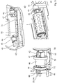
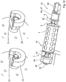
- Figure 1 shows the mould drum1 with a first front end 3 and a second front end 4.
- This mould drum 1 comprises on its surface a multitude of cavities 2, which are arranged around the entire circumference and which are open towards the surface. These cavities are utilized to form a food mass, preferably a meat mass into a desired 2D- or 3D-form, for example a patty.
- the mould drum comprises a multitude of cavities which are arranged in parallel. In the present case, one row of cavities comprises five cavities 2, which are filled simultaneously and emptied simultaneously.
- each cavity is filled with a food starting material, particularly with meat. Subsequently, this 2D- or 3D-formed product is removed from the cavity.
- the drum rotates.
- Each cavity comprises at least partially a porous structure; i.e. a at least partially porous bottom and/or a at least partially porous sidewall.
- This porous structure can be utilized to vent the cavity during filling, to apply pressurized air to the cavity to remove the product from the cavity and /or to clean the porous structure.
- All cavities 2 are connected to a passage 8, through which the cavities are vented and/or air or cleaning fluid is supplied. According to the present invention, this passage extends from the first front end 3 of the drum to the second front end 4 of the drum.
- the mould drum On one front side, here on the left front side 3, the mould drum further comprises a distributor 9, here a ring-shaped groove, in order to supply a cleaning fluid to all passages 8 simultaneously, which are fluid-wise connected to the distributor.
- form fit means 7, here embodied as pins, are arranged on the circumference of the front end 3 which are utilized to rotate the drum particularly during production. From the first front end 3 and the second front end 4 an axis of rotation 5 extends, respectively, which is used to bear the mould drum during its rotation in the production device and/or to bear the drum during its cleaning and/or to transport the drum. If needed, bearings 6 are fixed to the axis of rotation 5.
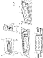
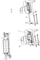
- FIG. 2 shows a first embodiment of the cleaning apparatus 20.
- This cleaning apparatus comprises a support frame 22, which is embodied in the present case as a partial segment of a cylindrical tube. Into this support frame, the axis of rotation 5 of the mould drum (please compare figure 1 ) is placed. On each side, the cleaning apparatus comprises cover- and fastening means 23, 26 which are axially movable. After the drum has been placed into the support frames, the cover- and/or fastening means 23, 26 are moved towards the drum, until they are in contact with the respective front end.
- Drive means 25, 28, preferably motor drive means can be utilized for this movement particularly in order to automatize the cleaning process.
- the person skilled in the art understands, however, that the means 23, 26 can also be moved manually.
- each cover- and/or fastening means 23, 26 comprises sealing means 24, 27 in order to avoid undesired leakage particularly cleaning- and/or drying-fluid leakage between the drum and the cover 23, 26.
- a distributor here a spray bar 31, with a multitude of nuzzles 30, rotates around the drum.
- the distributor 31 can be motor driven and/or can be rotated by the impulse of the jet that emerges each nozzle 30.
- the cleaning fluid sprayed on the outside of the drum cleans the surface of the drum and the surface of the cavity.
- the cover- and/or fastening means 26 comprises a cleaning fluid connection 32.
- a cleaning fluid is introduced into the cover and flows from there to the distribution groove 9, which is connected to all passages 8 of the mould drum.
- Figure 2b shows the cleaning apparatus 20 in its entirety.
- a hood can be opened, which extends essentially over the entire length of the cleaning apparatus in order to place the mould drum into the support frame 22.
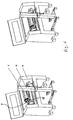
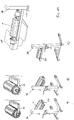
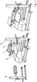
- FIG 3 shows further details of the cleaning apparatus according to figure 2 .
- the cleaning apparatus comprises drive means 49, 52 in order to rotate the spraying means 50, 51.
- a pinion 52 is arranged, which drives form-fit-means, here pins associated with the spray bar structure 51 to rotate the spray bar structure 51.
- an air source connection 53 is provided in the cover 46, which forces air into the distributor and thus into the passages and the cavities in order to dry the passages and the cavities.
- the mould drum can also be loaded into the cleaning unit from one of the front ends of the cleaning device 40.
- a movable unit For the loading of the mould drum into the cleaning device, a movable unit is used, which comprises a fork 58, which is height adjustable and on which the drum is placed so that the circumference of the drum sits on the fork 58.
- the fork 58 together with the drum is inserted into the cleaning unit 20 after the cleaning unit has been opened and then the fork 58 is lowered and the mould drum is placed on the support frame 42. Subsequently, the movable unit 57 is removed from the cleaning unit and the hood can be closed. The cleaning process can be inspected via a window 56.
- the valves for controlling the cleaning fluid can be operated by a PLC.
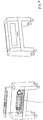
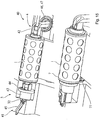
- FIGS 6 and 7 an alternative loading process is depicted.
- the mould drum is loaded from the front side.
- the axis of rotation 5 sits on the fork 58 and is then lowered into the support frame 52. Subsequently, the movable unit 36 is removed from the cleaning unit, the hood is closed and the cleaning process can start.
- the drum Since, in all applications the drum is not gripped by the movable unit, but sits on a fork, the movable unit is produced and operated easily. The drum is not damaged during transportation and/or insertion of the drum into the cleaning apparatus and/or into the cleaning apparatus.
- FIGS 8 - 10 show an alternative embodiment of the cleaning unit.
- the cover 63 is rotatable for example by motor means 65 or manually.
- the drum is loaded in the present case by a movable unit, which comprises a spindle 72, which can be inserted into the axis of rotation 5 of mould drum. After the mould drum has been placed on the support frame 62, the movable unit and thus the spindle is removed from the drum.
- a fork can be used to place the mould drum into the cleaning unit.
- cover- and/or fastening means can also be operated manually.
- all cleaning devices comprise collection means in order to collect the cleaning fluid and preferably recycle it into the cleaning process.
- Figure 11 shows the inventive cleaning process.
- the mould drum has been placed into the cleaning unit (please compare figure 11a )
- the cover- and/or fastening means 26 are brought into contact with the first front end 3.
- the cover- and/or fastening means 23 is still in its remote position.
- the cleaning fluid is introduced into the cover 26 and flows from there through the passages 8. Since the cover- and/or fastening means 23 is still in its remote position, the passages 8 are open at the second front end 4 of the mould drum 1 and the fluid introduced into the passage via cover 26 can escape from front end 4. Thus, the passages 8 are rinsed and food particles in the passage can be removed.
- the cleaning fluid can be water and if needed water with a cleaning agent.
- the water can be heated, however, in a first step always cold water should be used in order to avoid denaturalization of the protein structure of the meat.
- Figure 12 shows a first embodiment of the forming apparatus, which utilizes the mould drum as depicted and described in figure 1 to produce formed products, for example patties.
- the mould drum 1 is supported in a support frame 42 of the forming apparatus, which is for example part of the main frame of the forming apparatus.
- the support frame 42 is preferably engineered as described above.
- Bearings 21 are provided on both ends of the axis of rotation 5 to bear the rotating drum relative to the forming apparatus.
- the bearing can be a self-lubricating bearing but preferably the bearing is provided as a roll bearing, preferably as a stainless steel roll bearing.
- the bearing can be also of any other material, for example plastic, preferably high-performance plastic.
- the bearing must be resistant against the forces, which occur during the formation of formed products.
- the drum assembly 1 will be placed in or on the support frame by a movable unit which has been described above or which is described according to the subsequent figures.
- the cavities are vented via the porous structure and the passage 8 in the mould drum.
- air under pressure will be fed to the front end of the drum and flows from there through the passages 8 and the porous structure to the cavity of the mould drum 1.
- one front end 3, 4 of the mould drum is provided with a cover 43 with fluid connection points.
- cover 43 When the movable unit 36 has put the mould drum in/on the support frame 42, cover 43 will be moved by associated drive means such that the cover 43 is in contact with one of the front ends 3, 4 of the mould drum 1.
- This drive means can be motor or manual drive means. Once the cover is in contact with the front end of the drum, it will be secured in this position manually or automatically.
- the cover 43 which also secures the drum relative to the support frame is preferably provided with sealing means 44, for example of a labyrinth, lip seal or an O-ring seal to prevent a leakage between the cover 43 and the front end 3 of the drum 1.
- sealing means 44 for example of a labyrinth, lip seal or an O-ring seal to prevent a leakage between the cover 43 and the front end 3 of the drum 1.
- one connection point in cover 43 is connected with the ambient and/or preferably with a vacuum so that air can escape from the cavities during their filling. While or after the row of cavities has been filled with food starting material, the mould drum 1 continues its rotation and when it has reached its discharge position, one connection point in the cover 43 will be connected with a pressurized fluid source, for example an air source, for discharging the formed food product from the cavity 2.
- a pressurized fluid source for example an air source
- the fluid will flow from the fluid source via the cover 43 into the passage 8 and from there through the porous structure of one or more cavities, which are aligned in one row. It is also possible to provide the cover 43 with slots so that one or more passages 8 and/or one or more rows of cavities are provided with air in the discharge position.
- the cover 43 is therefore preferably an exchangeable piece, which can be adapted dependent on the product to be formed.
- the other front end 4, in the present case on the right hand side, is also provided with a cover 46 mainly to close the opening of the passages 8.
- the cover 46 is provided with sealing means 47, preferably embodied as described above, in order to prevent fluid-, preferably air-, leakage between this front end 4 of the mould drum and the cover 46.
- This cover can be either in a stand still position or can rotate together with the drum.
- Figure 13 shows the movable unit 36 in three different embodiments.
- the movable unit comprises a fork 58 with two arms which is adjustable in its height.
- the mould drum 1 is beared on the fork 58 of the movable unit 36.
- the axis of rotation 5, which extends from both ends of the mould drum 1 lies on the fork 58.
- a segment of the circumference of the drum lies on the fork 58.
- the front end of the fork comprises securing means, here indentations, in order to avoid that the drum rolls off the fork.
- the mould drum lies with its entire length on the fork.
- the forming apparatus preferably comprises guiding means (not depicted) to secure the movable unit 36 always in a defined position relative to the forming apparatus, in order to assure that the drum is placed on the support frame in the correct position.
- the fork 58 is lowered until the axis of rotation of the mould drum is fully supported by the support frame 42 of the forming apparatus.
- the lowering of the mould drum 1 can be carried out manually or automatically.
- the outfeed belt for the formed products must be shifted in a remote position. This is not the case in the embodiment according to figure 13c , as can be seen from figure 14 .
- the movable unit 36 carries drum 1 from underneath.
- Advantageous in this embodiment is that the drum can be placed and removed from the side of the forming apparatus.
- the outfeed belt need not be replaced in this embodiment according to the present invention.
- Figure 15 shows yet another embodiment.
- the support frame 42 at the front end 4 is designed differently.
- the cover 46 is not shifted linearly as in the preceding examples but is rotated into the locking position. This movement can be carried out manually or automatically.
- cover 46 comprises sealing means 47.
- the drive means 45 of the cover 43 is also also the drive means 45 of the cover 43. In the present case, this cover is operated manually.
- a leaver 45 also locks cover 43 once it is in contact with the front end 3 of the mould drum 1.
- Figure 16 shows the loading of the drum into the forming apparatus. Essentially, reference can be made to the disclosure made regarding figure 14 . However, the shifting and locking mechanisms of the covers 43, 46 is as described according to figure 15 .
- Figure 17 shows another loading mechanism of the mould drum 1.
- the mould drum comprises a hollow shaft or a hollow journal into which a spindle, which is part of the movable unit 36 is inserted. After the mould drum has been placed on support 42, the spindle is drawn out of the mould drum while removing the removable unit 36 from the forming apparatus.
Landscapes
- Engineering & Computer Science (AREA)
- Life Sciences & Earth Sciences (AREA)
- Mechanical Engineering (AREA)
- Structural Engineering (AREA)
- Transportation (AREA)
- General Engineering & Computer Science (AREA)
- Food Science & Technology (AREA)
- Zoology (AREA)
- Wood Science & Technology (AREA)
- Civil Engineering (AREA)
- Geology (AREA)
- Chemical & Material Sciences (AREA)
- Manufacturing & Machinery (AREA)
- Polymers & Plastics (AREA)
- Processing Of Meat And Fish (AREA)
- Formation And Processing Of Food Products (AREA)
- Manufacturing And Processing Devices For Dough (AREA)
- Cleaning By Liquid Or Steam (AREA)
- Meat, Egg Or Seafood Products (AREA)
- Cleaning In General (AREA)
Description
- The present invention relates to a method for cleaning a mould drum for moulding products from a mass of food starting material. The mould drum comprises one or more cavities with a mould cavity wall having at least partially a porous structure, whereas each cavity is connected to a passage.
- Hygiene is an important issue in the food processing industry. It is therefore important that machine parts, which are in contact with a food product, are cleaned regularly. Particularly, when using a drum with cavities with a porous structure for producing formed food products, the drum must be cleaned regularly and as soon as possible after the mould drum has been removed from the forming apparatus. If this is not done, for example dry meat will result in blocking of the pores of the porous cavity and will make it very difficult to clean these cavities.
- From
WO 2005/107481 A2 andUS 2009/134544 , a mould drum is known, which can be cleaned. However, the cleaning of this mould drum is not sufficient. Furthermore, from this patent application, a cleaning apparatus is known, which is however rather complicated and results in an insufficient cleaning. - It was therefore the objective of the present invention to provide a process for cleaning a mould drum which does not have the deficiencies according to the state of the art.
- This problem is attained with a process according to
claim 1. - The present invention relates to a process for cleaning a mould drum for moulding products from a mass of food starting material. Particularly, a mould drum for forming meat, for example into two- or three-dimensional patties. The mould drum comprises one, preferably more cavities, which are arranged on the surface of the drum. These cavities are preferably arranged around the entire circumference of the mould drum and a multitude of cavities are arranged in parallel; i.e. in rows. During the production, one row of cavities is filled and emptied simultaneously. During production, the drum rotates. Such a drum with porous cavities is and the respective food product forming device is for example disclosed in
US 3 427 649 or inUS 3 205 837 . Each mould cavity has a cavity wall; i.e. sidewall and/or a bottom, which is at least partially porous so that the cavity wall is permeable for gas and/or a cleaning fluid. The porous structure is for example a sintered structure. The porous structure has a multitude of channels, which extend from one surface of the structure to the other surface of the structure. Preferably, the channels are interconnected. The drum can comprise one cylindrical element which is entirely made from a porous material. Alternatively, the drum comprises porous inlays. Preferably, only the bottom is made at least partially from a porous material. - Furthermore, each cavity is connected to a passage, to vent the cavity during filling, provide pressurized gas in order to remove the product from the cavity and/or to supply a cleaning fluid to the cavity. Preferably, all cavities in one row are interconnected to each other by the passage. According to the present invention, this passage now extends from the first front end to the second front end of the mould drum, i.e. a cleaning fluid introduced at one front end can leave the drum at the other front end without being forced through the porous structure. This embodiment has the advantage that particularly during cleaning, the passage can be rinsed and food particles in the passage can be easily discharged from the passage.
- One front end comprises distribution means, a ring, for distributing a cleaning- and/or drying fluid to all passages. This distribution means interconnects all passages so that the cleaning- and/or drying fluid only has to be provided to the mould drum once; i.e. to the distributor, which distributes the cleaning- and/or drying-fluid to all passages.
- According to a preferred embodiment, the front end of the mould drum comprises form fit means to rotate the mould drum particularly during the production of the formed products. This form fit means can be for example a multitude of pins which are distributed equidistantly around the circumference of the front end.
- In another preferred embodiment, the mould drum comprises an axis of rotation that extends from both ends of the mould drum. This extension can be utilized to bear the mould drum for example in the forming- and/or cleaning apparatus. Furthermore, these extensions can be utilized to transport the mould drum for example from the production apparatus to the cleaning apparatus and vice versa. The axis of rotation can be part of the front end of the mould drum, can be fixed to the front end of the mould drum and/or can extend through the entire center axis of the mould drum.
- In another or a preferred embodiment the mould drum comprises a hollow axis of rotation and/or a hollow journal. This hollow axis of rotation and/or a hollow journal can be, for example, utilized to transport the mould drum, for example from the forming apparatus to a cleaning apparatus and vice versa.
- Another subject matter is an apparatus for the mould drum with supporting means for supporting the axis of the mould drum, whereas the cleaning apparatus comprises cover- and fastening means, which fastens the mould drum to the supporting means and/or covers one or both front ends of the mould drum.
- The disclosure regarding the mould drum also applies to the apparatus and vice versa.
- This embodiment relates to an apparatus for example for cleaning a mould drum from the inside; i.e. particularly the passage and/or the cavity and/or from the outside. This embodiment further relates to a forming apparatus in which the drum is utilized to form food products from a food starting material.
- The apparatus comprises supporting means for supporting the axis of the drum, which preferably does not rotate during the cleaning process and preferably rotates during the production process. Preferably, the axis of the drum fits on and/or in the supporting means and is at least partially secured in its position. For example, the supporting means can be utilized by a segment of a cylindrical sidewall of a tube.
- Furthermore, the apparatus comprises cover and/or fastening means, which fasten the mould drum to the supporting means and/or cover the front end of the mould drum, at least partially. By covering one front end of a mould drum, one end of the passage can be closed and/or two passages can be fluid-wise interconnected by the cover. Additionally, or alternatively, the cover can be connected to a fluid to eject the formed product, a cleaning- and/or drying fluid source to introduce a cleaning- and/or drying-fluid via the front end into the passage of the mould drum and force the cleaning- and/or drying-fluid through the porous structure and thus clean and/or dry it. Preferably, the cover- and the fastening means comprise sealing means to avoid that particularly ejection-, cleaning- and/or dry-fluid leaks unintentionally from one of the front ends.
- In another preferred embodiment, the cover and/or fastening means comprise drive means to move them from a fastening into a remote position and vice versa and preferably secure it in at least one of its respective position. These drive means can be operated by a motor and/or manually. This preferred embodiment of the present invention has the advantage that the mould drum can be placed on the support means of the apparatus. Subsequently, first one and then the second cover and/or fastening means can be automatically placed against the front end of the mould drum in order to secure the mould drum in its position and/or in order to clean the passages and/or the cavities.
- In another preferred embodiment, one cover and/or fastening means comprise an ejection-, cleaning- and/or drying-fluid connection to provide an ejection-, a cleaning- and/or drying-fluid to the passage and/or the cavity. Via the cover, the cavity can also be vented during filling of the cavity.
- Additionally, the apparatus is a cleaning apparatus, and comprises a nozzle that rotates around the drum in order to clean the circumference and/or the front end of the drum. The nozzle can be motor driven and/or driven by the emerging cleaning fluid jet.
- According to the present invention, the passages are rinsed from the first front end to the second front end. This embodiment of the inventive process has the advantage that food particles, which are inside the passage, are removed from the passage and not forced into the porous structure of the cavities.
- In a preferred embodiment, the cavities are rinsed with a cleaning fluid after the passage has been cleaned. Particularly after the passage has been cleaned, the opening of the passage in one front end will be closed so that the fluid introduced into the passage has to flow through the porous structure of the cavity and thereby cleans the porous structure.
- In another preferred embodiment, the passage and/or the cavity is dried after cleaning. This is preferably utilized by introducing air into the passage, which preferably firstly removes water from the passage and then dries the cavity. According to the invention, the outside of the drum is cleaned by a rotating nozzle. This has the advantage that the drum stands still during the cleaning process. In another preferred embodiment, the front ends are cleaned before the passage and/or the cavity is rinsed. This preferred embodiment of the present invention has the advantage that the front ends are already cleaned before they are covered by a cover.
- Disclosed is also a movable unit to transport the mould rum according to one of the preceding claims, whereas it comprises a fork and/or a spindle to bear the mould drum.
- The present invention is now explained according to
figures 1 - 17 . These explanations do not limit the scope of protection, which is defined by the appended claims. The explanation applies to all embodiments of the present invention, respectively. -
Figure 1 shows a mould drum. -
Figures 2 - 5 show a first embodiment of a cleaning apparatus. -
Figures 6 and7 show a different concept for loading the mould drum into the cleaning apparatus. -
Figures 8 - 10 show a second embodiment of the cleaning apparatus. -
Figure 11 show the inventive process. -
Figures 12 - 17 show different embodiments of the forming apparatus. -
Figure 1 shows the mould drum1 with a firstfront end 3 and a secondfront end 4. Thismould drum 1 comprises on its surface a multitude ofcavities 2, which are arranged around the entire circumference and which are open towards the surface. These cavities are utilized to form a food mass, preferably a meat mass into a desired 2D- or 3D-form, for example a patty. Additionally, along its axial extension, the mould drum comprises a multitude of cavities which are arranged in parallel. In the present case, one row of cavities comprises fivecavities 2, which are filled simultaneously and emptied simultaneously. During production, each cavity is filled with a food starting material, particularly with meat. Subsequently, this 2D- or 3D-formed product is removed from the cavity. During the production, the drum rotates. Each cavity comprises at least partially a porous structure; i.e. a at least partially porous bottom and/or a at least partially porous sidewall. This porous structure can be utilized to vent the cavity during filling, to apply pressurized air to the cavity to remove the product from the cavity and /or to clean the porous structure. Allcavities 2 are connected to apassage 8, through which the cavities are vented and/or air or cleaning fluid is supplied. According to the present invention, this passage extends from the firstfront end 3 of the drum to the secondfront end 4 of the drum. On one front side, here on the leftfront side 3, the mould drum further comprises adistributor 9, here a ring-shaped groove, in order to supply a cleaning fluid to allpassages 8 simultaneously, which are fluid-wise connected to the distributor. Furthermore, form fit means 7, here embodied as pins, are arranged on the circumference of thefront end 3 which are utilized to rotate the drum particularly during production. From the firstfront end 3 and the secondfront end 4 an axis ofrotation 5 extends, respectively, which is used to bear the mould drum during its rotation in the production device and/or to bear the drum during its cleaning and/or to transport the drum. If needed,bearings 6 are fixed to the axis ofrotation 5. -
Figure 2 shows a first embodiment of thecleaning apparatus 20. This cleaning apparatus comprises a support frame 22, which is embodied in the present case as a partial segment of a cylindrical tube. Into this support frame, the axis ofrotation 5 of the mould drum (please comparefigure 1 ) is placed. On each side, the cleaning apparatus comprises cover- and fastening means 23, 26 which are axially movable. After the drum has been placed into the support frames, the cover- and/or fastening means 23, 26 are moved towards the drum, until they are in contact with the respective front end. Drive means 25, 28, preferably motor drive means can be utilized for this movement particularly in order to automatize the cleaning process. The person skilled in the art understands, however, that themeans 23, 26 can also be moved manually. Preferably, themeans 23, 26 are moved one after the other, which will be described in more detail according tofigure 11 . At their contact side with the drum, each cover- and/or fastening means 23, 26 comprises sealing means 24, 27 in order to avoid undesired leakage particularly cleaning- and/or drying-fluid leakage between the drum and thecover 23, 26. During cleaning, the mould drum is stationary and a distributor, here a spray bar 31, with a multitude of nuzzles 30, rotates around the drum. The distributor 31 can be motor driven and/or can be rotated by the impulse of the jet that emerges each nozzle 30. The cleaning fluid sprayed on the outside of the drum cleans the surface of the drum and the surface of the cavity. Furthermore, the cover- and/or fastening means 26 comprises a cleaningfluid connection 32. Through this cleaningfluid connection 32, a cleaning fluid is introduced into the cover and flows from there to thedistribution groove 9, which is connected to allpassages 8 of the mould drum. Thus, thepassages 8 and/or the porous structure of the cavity can be cleaned which will be explained in further detail later on.Figure 2b shows thecleaning apparatus 20 in its entirety. In the present case, a hood can be opened, which extends essentially over the entire length of the cleaning apparatus in order to place the mould drum into the support frame 22. -
Figure 3 shows further details of the cleaning apparatus according tofigure 2 . As can be particularly seen fromfigure 3b , in the present case, the cleaning apparatus comprises drive means 49, 52 in order to rotate the spraying means 50, 51. At the end of arotating axis 49, apinion 52 is arranged, which drives form-fit-means, here pins associated with thespray bar structure 51 to rotate thespray bar structure 51. Besides the cleaningfluid connection 54, also anair source connection 53 is provided in thecover 46, which forces air into the distributor and thus into the passages and the cavities in order to dry the passages and the cavities. As can be particularly seen fromfigures 4 and5 , the mould drum can also be loaded into the cleaning unit from one of the front ends of thecleaning device 40. For the loading of the mould drum into the cleaning device, a movable unit is used, which comprises afork 58, which is height adjustable and on which the drum is placed so that the circumference of the drum sits on thefork 58. Thefork 58 together with the drum is inserted into thecleaning unit 20 after the cleaning unit has been opened and then thefork 58 is lowered and the mould drum is placed on thesupport frame 42. Subsequently, themovable unit 57 is removed from the cleaning unit and the hood can be closed. The cleaning process can be inspected via awindow 56. - There can be separate tanks for cleaning agents, descaler and disinfectant, pumps for spray nozzles and/or for internal cleaning drum filters. The valves for controlling the cleaning fluid can be operated by a PLC.
- In
figures 6 and7 an alternative loading process is depicted. In the present case, the mould drum is loaded from the front side. In the present case, the axis ofrotation 5 sits on thefork 58 and is then lowered into thesupport frame 52. Subsequently, themovable unit 36 is removed from the cleaning unit, the hood is closed and the cleaning process can start. - Since, in all applications the drum is not gripped by the movable unit, but sits on a fork, the movable unit is produced and operated easily. The drum is not damaged during transportation and/or insertion of the drum into the cleaning apparatus and/or into the cleaning apparatus.
-
Figures 8 - 10 show an alternative embodiment of the cleaning unit. As can be particularly seen fromfigure 8 , thecover 63 is rotatable for example by motor means 65 or manually. Other than that, reference is made to the description of the other figures. As can be particularly seen fromfigure 10 , the drum is loaded in the present case by a movable unit, which comprises a spindle 72, which can be inserted into the axis ofrotation 5 of mould drum. After the mould drum has been placed on thesupport frame 62, the movable unit and thus the spindle is removed from the drum. The person skilled in the art understands that in the present case also a fork can be used to place the mould drum into the cleaning unit. - The person skilled in the art understands that the cover- and/or fastening means can also be operated manually. The person skilled in the art further understands that all cleaning devices comprise collection means in order to collect the cleaning fluid and preferably recycle it into the cleaning process.
-
Figure 11 shows the inventive cleaning process. After the mould drum has been placed into the cleaning unit (please comparefigure 11a ), preferably first the front ends 3, 4 are cleaned by a nozzle 30. Subsequently, the cover- and/or fastening means 26 are brought into contact with the firstfront end 3. It should be noted that the cover- and/or fastening means 23 is still in its remote position. Subsequently, the cleaning fluid is introduced into the cover 26 and flows from there through thepassages 8. Since the cover- and/or fastening means 23 is still in its remote position, thepassages 8 are open at the secondfront end 4 of themould drum 1 and the fluid introduced into the passage via cover 26 can escape fromfront end 4. Thus, thepassages 8 are rinsed and food particles in the passage can be removed. This process step is depicted infigure 11b . Subsequently, as depicted infigure 11c , the cover- and/or fastening means 23 is moved from its remote position to the contact position with the mould drum. Now, thepassages 8 are closed at the secondfront end 4 and a cleaning- and/or drying-fluid forced into the passage, must leave the mould drum via theporous cavities 2 so that the porous structure of the cavities are cleaned during this stage of the cleaning process. After the cleaning of the porous structure is finalized, if desired, air can be forced through the passages. This can be done by either first bringing thecover 23 in its remote position again so that first the passages are dried and afterwards, after thecover 23 is in contact with the front end of the mould drum again, the porous structure of the cavities is dried. The cleaning fluid can be water and if needed water with a cleaning agent. The water can be heated, however, in a first step always cold water should be used in order to avoid denaturalization of the protein structure of the meat. -
Figure 12 shows a first embodiment of the forming apparatus, which utilizes the mould drum as depicted and described infigure 1 to produce formed products, for example patties. Themould drum 1 is supported in asupport frame 42 of the forming apparatus, which is for example part of the main frame of the forming apparatus. Thesupport frame 42 is preferably engineered as described above.Bearings 21 are provided on both ends of the axis ofrotation 5 to bear the rotating drum relative to the forming apparatus. The bearing can be a self-lubricating bearing but preferably the bearing is provided as a roll bearing, preferably as a stainless steel roll bearing. The bearing can be also of any other material, for example plastic, preferably high-performance plastic. The bearing must be resistant against the forces, which occur during the formation of formed products. Furthermore, the bearing must be resistant against the temperature and the cleaning agent in the cleaning apparatus as described above. Instead of the bearing on the journals of the drum, it is also possible to make the bearing part of the forming apparatus. Thedrum assembly 1 will be placed in or on the support frame by a movable unit which has been described above or which is described according to the subsequent figures. During filling of the cavity, it is desirable that the cavities are vented via the porous structure and thepassage 8 in the mould drum. During discharge of the formed food product from the cavity, air under pressure will be fed to the front end of the drum and flows from there through thepassages 8 and the porous structure to the cavity of themould drum 1. To achieve this, onefront end cover 43 with fluid connection points. When themovable unit 36 has put the mould drum in/on thesupport frame 42, cover 43 will be moved by associated drive means such that thecover 43 is in contact with one of the front ends 3, 4 of themould drum 1. This drive means can be motor or manual drive means. Once the cover is in contact with the front end of the drum, it will be secured in this position manually or automatically. Thecover 43 which also secures the drum relative to the support frame is preferably provided with sealing means 44, for example of a labyrinth, lip seal or an O-ring seal to prevent a leakage between thecover 43 and thefront end 3 of thedrum 1. During production, themould drum 1 is rotated while thecover 43 is preferably in a stationary position. As soon as one row of cavities has reached the filling position, one connection point incover 43 is connected with the ambient and/or preferably with a vacuum so that air can escape from the cavities during their filling. While or after the row of cavities has been filled with food starting material, themould drum 1 continues its rotation and when it has reached its discharge position, one connection point in thecover 43 will be connected with a pressurized fluid source, for example an air source, for discharging the formed food product from thecavity 2. The fluid will flow from the fluid source via thecover 43 into thepassage 8 and from there through the porous structure of one or more cavities, which are aligned in one row. It is also possible to provide thecover 43 with slots so that one ormore passages 8 and/or one or more rows of cavities are provided with air in the discharge position. It may be also desirable that even after discharge of the product, the fluid flow, for example the air flow, is maintained in order to clean the porous structure of the cavity. Thecover 43 is therefore preferably an exchangeable piece, which can be adapted dependent on the product to be formed. The otherfront end 4, in the present case on the right hand side, is also provided with acover 46 mainly to close the opening of thepassages 8. After themovable unit 36 has put themould drum 1 in the support frame of the formingapparatus 40, thecover 46 will be moved manually or automatically by associated drive means 48, which move thecover 46 from a remote position into a position where thecover 46 is in contact with thefront end 4 of themould drum 1. Preferably, thecover 46 is provided with sealing means 47, preferably embodied as described above, in order to prevent fluid-, preferably air-, leakage between thisfront end 4 of the mould drum and thecover 46. This cover can be either in a stand still position or can rotate together with the drum. -
Figure 13 shows themovable unit 36 in three different embodiments. In all cases the movable unit comprises afork 58 with two arms which is adjustable in its height. Themould drum 1 is beared on thefork 58 of themovable unit 36. In the embodiment, according tofigure 13a , the axis ofrotation 5, which extends from both ends of themould drum 1, lies on thefork 58. In the embodiment, according tofigure 13b , a segment of the circumference of the drum lies on thefork 58. In both cases, the front end of the fork comprises securing means, here indentations, in order to avoid that the drum rolls off the fork. In the embodiment, according tofigure 13c , the mould drum lies with its entire length on the fork. - The forming apparatus preferably comprises guiding means (not depicted) to secure the
movable unit 36 always in a defined position relative to the forming apparatus, in order to assure that the drum is placed on the support frame in the correct position. For placing themould drum 1 in/on thesupport frame 42, thefork 58 is lowered until the axis of rotation of the mould drum is fully supported by thesupport frame 42 of the forming apparatus. The lowering of themould drum 1 can be carried out manually or automatically. When utilizing the solution according tofigures 13a and 13b , the outfeed belt for the formed products must be shifted in a remote position. This is not the case in the embodiment according tofigure 13c , as can be seen fromfigure 14 . In this case, themovable unit 36 carries drum 1 from underneath. Advantageous in this embodiment is that the drum can be placed and removed from the side of the forming apparatus. The outfeed belt need not be replaced in this embodiment according to the present invention. -
Figure 15 shows yet another embodiment. In this case, thesupport frame 42 at thefront end 4 is designed differently. Here, thecover 46 is not shifted linearly as in the preceding examples but is rotated into the locking position. This movement can be carried out manually or automatically. Preferably, cover 46 comprises sealing means 47. Other than that reference is made to the description offigures 12 - 14 . Different in comparison to the other examples is also the drive means 45 of thecover 43. In the present case, this cover is operated manually. Aleaver 45 also locks cover 43 once it is in contact with thefront end 3 of themould drum 1. -
Figure 16 shows the loading of the drum into the forming apparatus. Essentially, reference can be made to the disclosure made regardingfigure 14 . However, the shifting and locking mechanisms of thecovers figure 15 . -
Figure 17 shows another loading mechanism of themould drum 1. In the present case, the mould drum comprises a hollow shaft or a hollow journal into which a spindle, which is part of themovable unit 36 is inserted. After the mould drum has been placed onsupport 42, the spindle is drawn out of the mould drum while removing theremovable unit 36 from the forming apparatus. -
- 1
- drum
- 2
- forming cavities
- 3
- first front end
- 4
- second front end
- 5
- axis of rotation
- 6
- bearing
- 7
- form-fit-means
- 8
- passage
- 9
- distributor
- 20
- cleaning apparatus
- 21
- bearing
- 22
- support frame
- 23
- cover-means, fastening-means
- 24
- sealing means for cover-
means 23 - 25
- drive-means for cover means 23
- 26
- cover-means, fastening-means
- 27
- sealing means for cover means 26
- 28
- drive-means for cover means 23
- 29
- drive-means for spray means 30, 31
- 30
- spray means, nozzle
- 31
- distributor
- 32
- cleaning fluid connection, air- and/or heated air- source connection for air supply during drying of the drum, ejecting air connection, venting connection during production
- 36
- movable unit
- 40
- cleaning apparatus, forming apparatus
- 41
- frame
- 42
- support frame
- 43
- cover-means, fastening-means
- 44
- sealing means for cover-
means 43 - 45
- drive-means for cover means 43/Leaver
- 46
- cover-means, fastening-means
- 47
- sealing means for cover means 46
- 48
- drive-means for cover means 43
- 49
- drive-means for spray means 50, 51
- 50
- spray means, nozzle
- 51
- distributor
- 52
- rotating means for the
distributor 51 - 53
- cleaning fluid connection passage and cavities
- 54
- air source connection
- 55
- cleaning
fluid connection distributor 51 - 56
- housing
- 57
- movable unit
- 58
- fork
- 60
- cleaning apparatus
- 61
- drum
- 62
- support frame
- 63
- cover-means, fastening-means
- 64
- sealing means for cover-
means 63 - 65
- drive-means for cover means 63
- 66
- cover-means, fastening-means
- 67
- sealing means for cover means 66
- 68
- drive-means for cover means 63
- 69
- drive-means for spray means
- 70
- spray means, nozzle
- 71
- distributor
- 72
- spindle
- 73
- cleaning fluid connection passage and cavities
- 74
- air source connection
- 75
- cleaning
fluid connection distributor 51 - 76
- housing
- 77
- rotating means drum
Claims (4)
- Process for the cleaning of a mould drum (1, 61) for moulding products from a mass of food starting material, comprising one or more cavities (2) with a mould cavity wall having at least partially a porous structure, whereas each cavity is connected to a passage (8), wherein the mould drum comprises a multitude of passages, each passage extending from the first front end (3) to the second front end (3) of the mould drum, wherein the first front end (3) comprises distribution means (9) configured as a ring that connects all passages so that a cleaning fluid is distributed to all passages in a cleaning apparatus (20, 40, 60), characterized in, that the passages are rinsed from the first front end (3) to the second front end (4) and that drum is cleaned from the outside by a rotating nozzle.
- Process according to claim 2, characterized in, that the cavity is rinsed, preferably after the passage has been cleaned.
- Process according to one of the preceding claims, characterized in, that the passage and or the cavity is dried after cleaning.
- Process according to one of the preceding claims, characterized in, that the front ends are cleaned before the passage and/or the cavity are rinsed.
Priority Applications (25)
| Application Number | Priority Date | Filing Date | Title |
|---|---|---|---|
| EP10016025.8A EP2468104B1 (en) | 2010-12-23 | 2010-12-23 | Cleaning method for a mould drum |
| PL10016025T PL2468104T3 (en) | 2010-12-23 | 2010-12-23 | Cleaning method for a mould drum |
| ES10016025T ES2699093T3 (en) | 2010-12-23 | 2010-12-23 | Method of cleaning a molding drum |
| ES22201076T ES3004662T3 (en) | 2010-12-23 | 2011-12-21 | Cleaning method and cleaning apparatus for a mould drum |
| CN201610975974.0A CN106509040B (en) | 2010-12-23 | 2011-12-21 | Mold roller and cleaning device for mold roller |
| CA2822257A CA2822257A1 (en) | 2010-12-23 | 2011-12-21 | Mould drum and cleaning apparatus for a mould drum |
| PL11805782.7T PL2654439T5 (en) | 2010-12-23 | 2011-12-21 | Mould drum and corresponding cleaning process |
| BR112013015618A BR112013015618B1 (en) | 2010-12-23 | 2011-12-21 | mold drum for molding products and process for cleaning a mold drum |
| RU2013134128/13A RU2598039C2 (en) | 2010-12-23 | 2011-12-21 | Mould drum and cleaning apparatus for a mould drum |
| CN201180062538.XA CN103429090B (en) | 2010-12-23 | 2011-12-21 | Die rollers and cleaning equipment for mold rollers |
| EP22201076.1A EP4154720B1 (en) | 2010-12-23 | 2011-12-21 | Cleaning method and cleaning apparatus for a mould drum |
| ES11805782T ES2692376T5 (en) | 2010-12-23 | 2011-12-21 | Molding drum and corresponding cleaning procedure |
| BR122018072368-8A BR122018072368B1 (en) | 2010-12-23 | 2011-12-21 | mobile unit to carry a mold drum |
| EP11805782.7A EP2654439B2 (en) | 2010-12-23 | 2011-12-21 | Mould drum and corresponding cleaning process |
| CN201610975735.5A CN106962446A (en) | 2010-12-23 | 2011-12-21 | Mold drum and the cleaning equipment for mold drum |
| EP18182630.6A EP3403506A1 (en) | 2010-12-23 | 2011-12-21 | Movable unit and method for transporting a mould drum |
| BR122018072369A BR122018072369B1 (en) | 2010-12-23 | 2011-12-21 | apparatus for a mold drum with support feature to support the drum geometric axis |
| PL22201076.1T PL4154720T3 (en) | 2010-12-23 | 2011-12-21 | Cleaning method and cleaning apparatus for a mould drum |
| PCT/EP2011/006458 WO2012084215A1 (en) | 2010-12-23 | 2011-12-21 | Mould drum and cleaning apparatus for a mould drum |
| JP2013545105A JP6169975B2 (en) | 2010-12-23 | 2011-12-21 | Mold drum and mold drum cleaning device |
| US13/994,973 US9162375B2 (en) | 2010-12-23 | 2011-12-21 | Mould drum and cleaning apparatus for a mould drum |
| US14/748,733 US9944504B2 (en) | 2010-12-23 | 2015-06-24 | Apparatus and methods for cleaning a mould drum |
| US14/748,725 US9637365B2 (en) | 2010-12-23 | 2015-06-24 | Movable unit for transport of a mould drum and methods thereof |
| JP2016078105A JP6193435B2 (en) | 2010-12-23 | 2016-04-08 | Mold drum cleaning method |
| US15/925,925 US10370229B2 (en) | 2010-12-23 | 2018-03-20 | Apparatus and methods for cleaning a mould drum |
Applications Claiming Priority (1)
| Application Number | Priority Date | Filing Date | Title |
|---|---|---|---|
| EP10016025.8A EP2468104B1 (en) | 2010-12-23 | 2010-12-23 | Cleaning method for a mould drum |
Publications (2)
| Publication Number | Publication Date |
|---|---|
| EP2468104A1 EP2468104A1 (en) | 2012-06-27 |
| EP2468104B1 true EP2468104B1 (en) | 2018-09-12 |
Family
ID=43821960
Family Applications (4)
| Application Number | Title | Priority Date | Filing Date |
|---|---|---|---|
| EP10016025.8A Revoked EP2468104B1 (en) | 2010-12-23 | 2010-12-23 | Cleaning method for a mould drum |
| EP11805782.7A Active EP2654439B2 (en) | 2010-12-23 | 2011-12-21 | Mould drum and corresponding cleaning process |
| EP18182630.6A Pending EP3403506A1 (en) | 2010-12-23 | 2011-12-21 | Movable unit and method for transporting a mould drum |
| EP22201076.1A Active EP4154720B1 (en) | 2010-12-23 | 2011-12-21 | Cleaning method and cleaning apparatus for a mould drum |
Family Applications After (3)
| Application Number | Title | Priority Date | Filing Date |
|---|---|---|---|
| EP11805782.7A Active EP2654439B2 (en) | 2010-12-23 | 2011-12-21 | Mould drum and corresponding cleaning process |
| EP18182630.6A Pending EP3403506A1 (en) | 2010-12-23 | 2011-12-21 | Movable unit and method for transporting a mould drum |
| EP22201076.1A Active EP4154720B1 (en) | 2010-12-23 | 2011-12-21 | Cleaning method and cleaning apparatus for a mould drum |
Country Status (10)
| Country | Link |
|---|---|
| US (4) | US9162375B2 (en) |
| EP (4) | EP2468104B1 (en) |
| JP (2) | JP6169975B2 (en) |
| CN (2) | CN106962446A (en) |
| BR (3) | BR122018072369B1 (en) |
| CA (1) | CA2822257A1 (en) |
| ES (3) | ES2699093T3 (en) |
| PL (3) | PL2468104T3 (en) |
| RU (1) | RU2598039C2 (en) |
| WO (1) | WO2012084215A1 (en) |
Families Citing this family (40)
| Publication number | Priority date | Publication date | Assignee | Title |
|---|---|---|---|---|
| NL1026171C2 (en) | 2004-05-11 | 2005-11-14 | Stork Titan Bv | To shape. |
| ES2603552T3 (en) | 2010-11-04 | 2017-02-28 | Gea Food Solutions Bakel B.V. | Mass distribution device and molding device |
| EP2468104B1 (en) | 2010-12-23 | 2018-09-12 | GEA Food Solutions Bakel B.V. | Cleaning method for a mould drum |
| ES2541841T3 (en) | 2011-01-25 | 2015-07-27 | Gea Food Solutions Bakel B.V. | Food production chain |
| WO2012107236A2 (en) | 2011-02-10 | 2012-08-16 | Gea Cfs Bakel B.V. | Food forming drum |
| CN103517771A (en) * | 2011-05-18 | 2014-01-15 | 巴斯夫欧洲公司 | Device and method for draining and rinsing containers filled with fluid |
| US9554593B2 (en) | 2011-07-25 | 2017-01-31 | Gea Food Solutions Bakel B.V. | Food forming apparatus with a food feed member |
| EP3508065B1 (en) | 2012-01-20 | 2024-07-03 | GEA Food Solutions Bakel B.V. | Mass supply system and method |
| US8851871B1 (en) * | 2013-01-10 | 2014-10-07 | Us Synthetic Corporation | High-temperature high-pressure presses (HTHP) presses, systems for HTHP presses and related methods |
| RU2682199C2 (en) * | 2013-02-01 | 2019-03-15 | Геа Фуд Сольюшнс Бакел Б.В. | Food forming concept |
| CA2908657A1 (en) * | 2013-04-03 | 2014-10-09 | Gea Food Solutions Bakel B.V. | Knock-out unit |
| US9861108B2 (en) | 2013-05-03 | 2018-01-09 | Gea Food Solutions Bakel B.V. | Sealing member for a food forming drum |
| CA2979497A1 (en) * | 2015-03-13 | 2016-09-22 | Gea Food Solutions Bakel B.V. | Method for cleaning and storing of a mould drum |
| NL2016419B1 (en) * | 2016-03-11 | 2017-10-02 | Marel Townsend Further Proc Bv | Method for cleaning and/ or evaluating a food products mould drum and a combination of such a food products mould drum and a mould drum cleaning and/ or evaluating device. |
| RU2720918C1 (en) * | 2016-09-16 | 2020-05-14 | Хаас Фуд Экуипмент ГмбХ | Extruder machine for edible dough |
| BR112019010985A2 (en) | 2016-11-29 | 2019-10-15 | Gea Food Solutions Bakel Bv | method for cleaning a impression cylinder provided with a porous plastic structure |
| FR3070829B1 (en) * | 2017-09-11 | 2019-09-13 | Marel France | TOOLING COMPRISING A POROUS MATERIAL FOOTPRINT, WALK-FORMING MACHINE AND FOOT-WASHING MACHINE COMPRISING SUCH TOOLS |
| BR112020009007A2 (en) | 2017-11-07 | 2020-11-17 | Gea Food Solutions Bakel B.V. | food processing equipment with plasma activated water cleaning |
| RU179805U1 (en) * | 2017-11-14 | 2018-05-24 | Общество с ограниченной ответственностью "Пелигрин Матен" | Forming drum cleaning device |
| CN108835153B (en) * | 2018-06-09 | 2021-04-02 | 中山市福德利得食品科技有限公司 | Extrusion type food raw material processing device |
| CN109078879B (en) * | 2018-08-06 | 2021-08-13 | 漳州和品工贸有限公司 | Engineering plastic surface treatment system and plastic surface treatment process thereof |
| US11134712B2 (en) | 2018-08-08 | 2021-10-05 | Mp Equipment Llc | Adjustable breading machine and method of operation |
| CN109367107A (en) * | 2018-11-01 | 2019-02-22 | 大余县萤通工贸有限公司 | A kind of pressure ball equipment for Fluorite pellet production |
| CN109926378B (en) * | 2018-12-20 | 2023-11-21 | 莆田市博泰动力设备有限公司 | High-pressure cleaning machine for control valve |
| NL2022602B1 (en) * | 2019-02-19 | 2020-08-31 | Marel Further Proc Bv | Movable mould member for moulding food products |
| BR112021017251A2 (en) * | 2019-03-11 | 2021-11-09 | Marel France | Methods for cleaning food product molding inserts and for producing food products, installation for producing food products, insert conveyor, and insert cleaning device |
| BR112021025657A2 (en) | 2019-06-19 | 2022-02-08 | Gea Food Solutions Bakel Bv | System for molding products from a food dough comprising a production device and method for cleaning a molding cylinder |
| NL2025218B1 (en) * | 2020-03-26 | 2021-10-20 | Marel Further Proc Bv | System for moulding comprising a mould member, a method for moulding and a method for configuring a mould member |
| NL2025770B1 (en) * | 2020-06-08 | 2022-01-28 | Marel Further Proc Bv | A rotary mould drum system configured for use in an installation for moulding food products from a pumpable foodmass |
| CN113944743A (en) * | 2020-07-17 | 2022-01-18 | 湖南桃花鸭食品科技有限公司 | A kind of cleaning device for processing braised meat products |
| CN112357834B (en) * | 2020-07-20 | 2022-05-13 | 万向一二三股份公司 | Avoid hindering fork truck arm of lithium cell utmost point book |
| CN112354982B (en) * | 2020-11-09 | 2021-11-30 | 中国石油大学(华东) | Porous rotary jet structure washing device |
| CN112425635A (en) * | 2020-11-13 | 2021-03-02 | 山东鲁拓畜产品有限公司 | Raw meat cleaning device is used in preparation of beef jerky |
| CN112222060A (en) * | 2020-12-08 | 2021-01-15 | 江苏金科森电子科技有限公司 | Mechanical equipment processing mould cleaning device |
| WO2022233817A2 (en) * | 2021-05-03 | 2022-11-10 | Gea Food Solutions Bakel B.V. | Porous mould drum for poultry, pork, meat-replacement and vegetarian food |
| CN113441450B (en) * | 2021-05-21 | 2022-10-21 | 重庆渝每滋农业科技发展有限公司 | Bean product raw materials for production cleaning equipment |
| CN114472359B (en) * | 2021-12-24 | 2023-12-01 | 温州卓人汽车电控有限公司 | Oil removing tool for fuel pump |
| CN115156149B (en) * | 2022-07-07 | 2024-08-02 | 中国大唐集团科学技术研究院有限公司中南电力试验研究院 | Vibration mill millstone cleaner |
| CN115254835A (en) * | 2022-07-11 | 2022-11-01 | 苏州模方包装容器有限公司 | Sorting, cleaning and packaging equipment and method for daily packaging bottles |
| EP4566805A1 (en) * | 2023-12-04 | 2025-06-11 | ANDRITZ Feed & Biofuel A/S | Die for a pellet mill and method for die identification |
Citations (4)
| Publication number | Priority date | Publication date | Assignee | Title |
|---|---|---|---|---|
| US4989786A (en) | 1989-01-27 | 1991-02-05 | Kraenzle Josef | Rotatable nozzle in particular for high pressure cleaning apparatuses |
| EP1136133A2 (en) | 2000-02-16 | 2001-09-26 | Spraying Systems Deutschland GmbH | Cleaning nozzle |
| WO2005107481A2 (en) | 2004-05-11 | 2005-11-17 | Stork Titan B.V. | Moulding |
| US20090134544A1 (en) | 2007-11-28 | 2009-05-28 | Stork Titan B.V. | Mould member for moulding three-dimensional products, system and methods of manufacturing a mould member |
Family Cites Families (87)
| Publication number | Priority date | Publication date | Assignee | Title |
|---|---|---|---|---|
| US2657423A (en) | 1947-07-17 | 1953-11-03 | Frank S Elsaesser | Machine for making hamburg steak patties |
| US3205837A (en) | 1962-09-19 | 1965-09-14 | Rudolph J Fay | Apparatus for producing edible dough products |
| US3213486A (en) | 1962-12-31 | 1965-10-26 | Frederick H Blake | Molding machines |
| US3177524A (en) | 1963-03-25 | 1965-04-13 | Claude M Snyder | Meat molding machine |
| GB1015820A (en) | 1964-02-14 | 1966-01-05 | Marlen Equipment Company | Machine for forming meat balls and automatically placing the meat balls in cans |
| US3347176A (en) | 1964-10-22 | 1967-10-17 | Formatic Inc | Method and apparatus for making patties |
| US3427649A (en) | 1966-09-12 | 1969-02-11 | Rudolph J Fay | Method and apparatus for producing shaped articles |
| DE1807714C2 (en) * | 1968-11-08 | 1971-01-04 | Degussa | Process and device for continuous pre-compression and simultaneous shaping of finely divided materials |
| US3724026A (en) | 1970-10-30 | 1973-04-03 | Armour & Co | Producing molded meat sticks |
| US3750232A (en) | 1972-02-25 | 1973-08-07 | Hollymatic Corp | Molding apparatus |
| US3823633A (en) | 1972-06-05 | 1974-07-16 | Consolidated Educational Publi | Self-adjusting plural blade cutting roller with cushioned anvil roller |
| US3899273A (en) * | 1973-07-23 | 1975-08-12 | Ore Ida Foods | Food forming apparatus |
| US3991440A (en) * | 1974-10-25 | 1976-11-16 | Castle & Cooke, Inc. | Food pellet former |
| US3998574A (en) | 1975-02-01 | 1976-12-21 | Blake Frederick H | Processed-paced, fluidic control system for molding machines |
| FR2387609A1 (en) | 1977-04-19 | 1978-11-17 | Zaugg Jean | Demoulding food prod. esp. cooked ham encased in jelly - with pneumatic hammer blow on inverted mould followed by air displacement |
| US4182003A (en) | 1978-02-28 | 1980-01-08 | Formax, Inc. | Food patty molding machine |
| US4212609A (en) | 1978-05-17 | 1980-07-15 | Fay Rudolph J | Method and apparatus for producing shaped and sized food articles |
| JPS5743637A (en) * | 1980-08-02 | 1982-03-11 | Nichiro Gyogyo Kk | Continuous dehulling and meat taking method of small shrimp or eupausia |
| US4418446A (en) | 1981-03-05 | 1983-12-06 | Formax, Inc. | Mold assembly for food patty molding machine |
| US4630425A (en) | 1981-05-08 | 1986-12-23 | Parker Drilling Company | Erection means for portable drilling system |
| JPS5856632A (en) * | 1982-09-02 | 1983-04-04 | ブレビル・ホ−ルデイングス・プロプライエタリ−・リミテツド | Food extruder |
| JPH0646014B2 (en) | 1983-07-07 | 1994-06-15 | トヨタ自動車株式会社 | Idle speed control method for vehicle engine |
| JPS6017235U (en) * | 1983-07-13 | 1985-02-05 | 愛知電機株式会社 | Stirring drum cleaning device |
| CA1202933A (en) * | 1984-01-13 | 1986-04-08 | Gerald Doak | Sanitizing a drink supply system |
| US4657469A (en) * | 1984-06-21 | 1987-04-14 | Beierle Carl F | Trestle-type reel carrier |
| US4736570A (en) | 1984-12-03 | 1988-04-12 | Food Machinery Sales, Inc. | Automatic cookie loading system with double discharge |
| US4630426A (en) | 1985-05-17 | 1986-12-23 | Gentry James C | Food unit making and packaging apparatus and method |
| US4625612A (en) | 1985-09-23 | 1986-12-02 | Riccobin & Martin | Rotary portapunch assembly |
| US4768325A (en) | 1987-10-07 | 1988-09-06 | Alfa-Laval Ab | Paper interleaver for food patty molding machine |
| US4987643A (en) | 1989-08-10 | 1991-01-29 | Marlen Research Corporation | Slide plate patty forming apparatus |
| DE4109888A1 (en) * | 1991-03-26 | 1992-10-01 | Leybold Ag | DEVICE FOR HOLDING AND GUIDING AN AXLE OR SHAFT OR A BEARING RING |
| US5357993A (en) | 1992-09-25 | 1994-10-25 | St Martin Marty | Produce washer |
| US5503033A (en) | 1993-08-10 | 1996-04-02 | Tric Holdings Limited | Method and servicing interior of large container and service apparatus |
| US5749203A (en) | 1994-09-23 | 1998-05-12 | Kimberly-Clark Corporation | Method of packaging a medical article |
| JP2632506B2 (en) * | 1994-10-19 | 1997-07-23 | 洋志 岩佐 | Blowfish peeling machine |
| US5795610A (en) | 1995-07-10 | 1998-08-18 | Stein, Inc. | Food molding apparatus and method of forming food products |
| NL1003568C2 (en) | 1996-07-11 | 1998-01-15 | Tetra Laval Food Koppens Bv | Molding system for forming a mass such as a meat mass. |
| US6368092B1 (en) | 1998-06-05 | 2002-04-09 | Formax, Inc. | Knock-out system for patty molding machine |
| US6131372A (en) | 1998-12-14 | 2000-10-17 | Food Machinery Sales, Inc. | Article metering device and method of metering articles |
| US6371278B1 (en) | 1999-11-04 | 2002-04-16 | Colin R. Hart | Patty loader and method |
| US6270826B1 (en) * | 1999-12-13 | 2001-08-07 | Mars Incorporated | Method for forming confectionery product |
| JP2001200767A (en) | 2000-01-18 | 2001-07-27 | Mitsubishi Heavy Ind Ltd | Cleaning device for air suction filter in supercharger |
| JP2001327812A (en) * | 2000-03-15 | 2001-11-27 | Matsushita Electric Works Ltd | Bath water cleaning device |
| JP4197826B2 (en) | 2000-04-20 | 2008-12-17 | 株式会社紀文食品 | Drum forming equipment |
| JP3522702B2 (en) * | 2001-01-31 | 2004-04-26 | 月島機械株式会社 | Screw press filter |
| US20030004263A1 (en) * | 2001-06-15 | 2003-01-02 | Schmidt Robert C. | Reactive hot melt adhesive |
| NL1018541C2 (en) * | 2001-07-13 | 2003-01-14 | Stork P M T B V | Device for massaging products. |
| DE60126355T2 (en) * | 2001-09-05 | 2007-10-31 | Courtoy N.V. | RUNNING TABLET PRESSING AND METHOD FOR CLEANING A PRESS |
| US6686308B2 (en) | 2001-12-03 | 2004-02-03 | 3M Innovative Properties Company | Supported nanoparticle catalyst |
| NL1020942C2 (en) * | 2002-06-26 | 2003-12-30 | Stork Titan Bv | Forming device. |
| US7146992B2 (en) | 2002-07-02 | 2006-12-12 | Maytag Corporation | Dishwasher pump and filtration system |
| AU2003225709A1 (en) | 2002-09-04 | 2004-03-29 | The University Of Chicago | Novel catalyst for selective nox reduction using hydrocarbons |
| US7021922B2 (en) | 2003-07-18 | 2006-04-04 | James Douglas Azzar | Apparatus for portioning flowable materials |
| DE502004011215D1 (en) | 2003-07-23 | 2010-07-08 | Cfs Buehl Gmbh | AXIAL MOVABLE KNIFE |
| US7163391B2 (en) | 2003-08-20 | 2007-01-16 | Formax, Inc. | Molding apparatus for forming food patties having top and bottom surface contours |
| ITMI20031891A1 (en) | 2003-10-02 | 2005-04-03 | Crm Cost Revisioni Mecc | MACHINE FOR FORMING FOOD PRODUCTS OF THE HAMBURGER OR SIMILAR TYPE, WITH HIGH VERSATILITY OF USE. |
| US7175417B2 (en) | 2004-03-26 | 2007-02-13 | Formax, Inc. | Apparatus for forming food patties having surface indentations |
| CN2689707Y (en) * | 2004-04-23 | 2005-04-06 | 曾育川 | Roller Biscuit Forming Mold |
| DE102004029408A1 (en) | 2004-06-19 | 2006-03-30 | Züger Frischkäse AG | Apparatus and method for producing shaped food articles |
| US7824172B2 (en) | 2004-07-15 | 2010-11-02 | Azzar James D | Food portioning system |
| US7467636B2 (en) | 2004-08-31 | 2008-12-23 | Maytag Corporation | Dishwasher pump and filtration system |
| GB0500564D0 (en) * | 2005-01-12 | 2005-02-16 | Mechandling Ltd | Roll or reel handling apparatus |
| GB0512873D0 (en) * | 2005-06-24 | 2005-08-03 | Ibm | A message generator |
| DE102005032222A1 (en) * | 2005-07-09 | 2007-01-25 | Schaeffler Kg | Bearing arrangement for supporting at least one machine element on a support |
| DE102005044984B3 (en) * | 2005-09-20 | 2007-01-25 | Carl Freudenberg Kg | Trolley for cleaning tasks has an extendable frame made from combinable elements with releasable connections and U-shaped parts |
| DE102006020361A1 (en) | 2006-02-09 | 2007-08-16 | Cfs Germany Gmbh | Packaging machine for producing a package with a return in the packaging trough edge |
| US7748393B2 (en) * | 2006-06-05 | 2010-07-06 | Dipanni Helen | Apparatus and method for cleaning, drying and sanitizing produce |
| EP1920847B1 (en) | 2006-11-09 | 2017-04-05 | Nilfisk A/S | Rotating nozzle for a high-pressure cleaning device |
| US7677880B2 (en) | 2007-01-23 | 2010-03-16 | Formax, Inc. | Apparatus for forming hand-formed style patty using a patty-forming machine |
| US20090013454A1 (en) * | 2007-07-12 | 2009-01-15 | David Landsberger | Toilet seat elevator assembly |
| US7931461B2 (en) * | 2007-11-28 | 2011-04-26 | Stork Titan B.V. | Mould member for moulding three-dimensional products, system and methods of manufacturing a mould member |
| DE102008016246B4 (en) * | 2008-03-27 | 2023-06-15 | Fortuna Maschinen Gmbh | Device and method for rounding dough pieces |
| FR2929867B1 (en) * | 2008-04-10 | 2010-08-20 | Rotobloc Psp | HANDLING DEVICE ADAPTED TO A LIFTING MACHINE FOR HANDLING PRODUCTS SUCH AS COILS AND LIFTING EQUIPMENT EQUIPPED WITH SUCH A DEVICE |
| US8360459B2 (en) * | 2008-04-11 | 2013-01-29 | Dane Technologies, Inc. | Cart transporting apparatus |
| EP2140767B1 (en) | 2008-07-04 | 2014-05-07 | CFS Bakel B.V. | Food product forming apparatus and process |
| NL2002672C2 (en) | 2009-03-26 | 2010-09-28 | Stork Titan Bv | MASS DIVIDING DEVICE AND MOLDING DEVICE CONTAINING SUCH A MASS DIVIDING DEVICE. |
| CN201406104Y (en) * | 2009-04-10 | 2010-02-17 | 苏州达信科技电子有限公司 | Transport device |
| CN201472818U (en) * | 2009-09-17 | 2010-05-19 | 蔡强生 | Barreled bucket transport and storage device |
| EP2901863A3 (en) | 2010-04-23 | 2016-03-30 | GEA Food Solutions Bakel B.V. | 3D-food product forming apparatus and process |
| CN201647427U (en) * | 2010-04-27 | 2010-11-24 | 上海依赛工业有限公司 | Oil drum shelf structure |
| US8793821B2 (en) * | 2010-07-12 | 2014-08-05 | Doug Fowkes | Cushion with double stacked off-set honeycomb |
| EP3072395A3 (en) * | 2010-07-20 | 2016-10-19 | Formax, Inc. | Rotary mold system |
| CN103249308A (en) | 2010-08-31 | 2013-08-14 | Cfs巴克尔股份有限公司 | pie forming equipment |
| ES2603552T3 (en) | 2010-11-04 | 2017-02-28 | Gea Food Solutions Bakel B.V. | Mass distribution device and molding device |
| EP2468104B1 (en) | 2010-12-23 | 2018-09-12 | GEA Food Solutions Bakel B.V. | Cleaning method for a mould drum |
| ES2541841T3 (en) | 2011-01-25 | 2015-07-27 | Gea Food Solutions Bakel B.V. | Food production chain |
| WO2012107236A2 (en) | 2011-02-10 | 2012-08-16 | Gea Cfs Bakel B.V. | Food forming drum |
-
2010
- 2010-12-23 EP EP10016025.8A patent/EP2468104B1/en not_active Revoked
- 2010-12-23 ES ES10016025T patent/ES2699093T3/en active Active
- 2010-12-23 PL PL10016025T patent/PL2468104T3/en unknown
-
2011
- 2011-12-21 BR BR122018072369A patent/BR122018072369B1/en not_active IP Right Cessation
- 2011-12-21 PL PL22201076.1T patent/PL4154720T3/en unknown
- 2011-12-21 EP EP11805782.7A patent/EP2654439B2/en active Active
- 2011-12-21 WO PCT/EP2011/006458 patent/WO2012084215A1/en not_active Ceased
- 2011-12-21 ES ES22201076T patent/ES3004662T3/en active Active
- 2011-12-21 EP EP18182630.6A patent/EP3403506A1/en active Pending
- 2011-12-21 EP EP22201076.1A patent/EP4154720B1/en active Active
- 2011-12-21 CA CA2822257A patent/CA2822257A1/en not_active Abandoned
- 2011-12-21 US US13/994,973 patent/US9162375B2/en active Active
- 2011-12-21 ES ES11805782T patent/ES2692376T5/en active Active
- 2011-12-21 BR BR122018072368-8A patent/BR122018072368B1/en not_active IP Right Cessation
- 2011-12-21 RU RU2013134128/13A patent/RU2598039C2/en active
- 2011-12-21 PL PL11805782.7T patent/PL2654439T5/en unknown
- 2011-12-21 JP JP2013545105A patent/JP6169975B2/en not_active Expired - Fee Related
- 2011-12-21 CN CN201610975735.5A patent/CN106962446A/en active Pending
- 2011-12-21 CN CN201610975974.0A patent/CN106509040B/en active Active
- 2011-12-21 BR BR112013015618A patent/BR112013015618B1/en not_active IP Right Cessation
-
2015
- 2015-06-24 US US14/748,733 patent/US9944504B2/en active Active
- 2015-06-24 US US14/748,725 patent/US9637365B2/en active Active
-
2016
- 2016-04-08 JP JP2016078105A patent/JP6193435B2/en not_active Expired - Fee Related
-
2018
- 2018-03-20 US US15/925,925 patent/US10370229B2/en active Active
Patent Citations (4)
| Publication number | Priority date | Publication date | Assignee | Title |
|---|---|---|---|---|
| US4989786A (en) | 1989-01-27 | 1991-02-05 | Kraenzle Josef | Rotatable nozzle in particular for high pressure cleaning apparatuses |
| EP1136133A2 (en) | 2000-02-16 | 2001-09-26 | Spraying Systems Deutschland GmbH | Cleaning nozzle |
| WO2005107481A2 (en) | 2004-05-11 | 2005-11-17 | Stork Titan B.V. | Moulding |
| US20090134544A1 (en) | 2007-11-28 | 2009-05-28 | Stork Titan B.V. | Mould member for moulding three-dimensional products, system and methods of manufacturing a mould member |
Also Published As
Similar Documents
| Publication | Publication Date | Title |
|---|---|---|
| EP2468104B1 (en) | Cleaning method for a mould drum | |
| US20210244068A1 (en) | Moulding | |
| CN103687711B (en) | Method and device for cleaning and/or disinfecting a device for producing containers filled with liquid fillings | |
| US20190275564A1 (en) | Method to clean a mould drum provided with a plastic porous structure | |
| FR2515933A1 (en) | METHOD AND DEVICE FOR CONTINUOUS SHAPING AND HEAT TREATMENT OF FOOD MASSES, ESPECIALLY MEAT MASSES | |
| CN114040678B (en) | System for molding products from food mass | |
| EP3393529B1 (en) | Method of sterilizing the means of stretching a container moulding device and container manufacturing plant | |
| CN103429090B (en) | Die rollers and cleaning equipment for mold rollers | |
| NL2033819B1 (en) | Method for cleaning a food products mould member | |
| FR3094900A1 (en) | Washing facility for already used packaging and washing process |
Legal Events
| Date | Code | Title | Description |
|---|---|---|---|
| AK | Designated contracting states |
Kind code of ref document: A1 Designated state(s): AL AT BE BG CH CY CZ DE DK EE ES FI FR GB GR HR HU IE IS IT LI LT LU LV MC MK MT NL NO PL PT RO RS SE SI SK SM TR |
|
| AX | Request for extension of the european patent |
Extension state: BA ME |
|
| PUAI | Public reference made under article 153(3) epc to a published international application that has entered the european phase |
Free format text: ORIGINAL CODE: 0009012 |
|
| 17P | Request for examination filed |
Effective date: 20130102 |
|
| 17Q | First examination report despatched |
Effective date: 20150203 |
|
| RIC1 | Information provided on ipc code assigned before grant |
Ipc: A22C 7/00 20060101AFI20150128BHEP Ipc: B29C 33/72 20060101ALI20150128BHEP Ipc: B30B 11/12 20060101ALI20150128BHEP Ipc: B08B 9/00 20060101ALI20150128BHEP Ipc: B08B 3/02 20060101ALI20150128BHEP Ipc: B08B 3/04 20060101ALI20150128BHEP Ipc: F16C 13/00 20060101ALI20150128BHEP Ipc: F16C 41/00 20060101ALI20150128BHEP Ipc: B30B 11/16 20060101ALI20150128BHEP |
|
| TPAC | Observations filed by third parties |
Free format text: ORIGINAL CODE: EPIDOSNTIPA |
|
| STAA | Information on the status of an ep patent application or granted ep patent |
Free format text: STATUS: EXAMINATION IS IN PROGRESS |
|
| RIC1 | Information provided on ipc code assigned before grant |
Ipc: F16C 13/00 20060101ALI20171024BHEP Ipc: B08B 3/02 20060101ALI20171024BHEP Ipc: A22C 7/00 20060101AFI20171024BHEP Ipc: B30B 11/12 20060101ALI20171024BHEP Ipc: B08B 9/00 20060101ALI20171024BHEP Ipc: F16C 41/00 20060101ALI20171024BHEP Ipc: B29C 33/72 20060101ALI20171024BHEP Ipc: B08B 3/04 20060101ALI20171024BHEP Ipc: B30B 11/16 20060101ALI20171024BHEP |
|
| GRAP | Despatch of communication of intention to grant a patent |
Free format text: ORIGINAL CODE: EPIDOSNIGR1 |
|
| STAA | Information on the status of an ep patent application or granted ep patent |
Free format text: STATUS: GRANT OF PATENT IS INTENDED |
|
| INTG | Intention to grant announced |
Effective date: 20180404 |
|
| GRAS | Grant fee paid |
Free format text: ORIGINAL CODE: EPIDOSNIGR3 |
|
| GRAA | (expected) grant |
Free format text: ORIGINAL CODE: 0009210 |
|
| STAA | Information on the status of an ep patent application or granted ep patent |
Free format text: STATUS: THE PATENT HAS BEEN GRANTED |
|
| RAP1 | Party data changed (applicant data changed or rights of an application transferred) |
Owner name: GEA FOOD SOLUTIONS BAKEL B.V. |
|
| AK | Designated contracting states |
Kind code of ref document: B1 Designated state(s): AL AT BE BG CH CY CZ DE DK EE ES FI FR GB GR HR HU IE IS IT LI LT LU LV MC MK MT NL NO PL PT RO RS SE SI SK SM TR |
|
| REG | Reference to a national code |
Ref country code: GB Ref legal event code: FG4D |
|
| RIN1 | Information on inventor provided before grant (corrected) |
Inventor name: VAN GERWEN, HENDRIKUS PETRUS GERARDUS |
|
| REG | Reference to a national code |
Ref country code: CH Ref legal event code: EP |
|
| REG | Reference to a national code |
Ref country code: IE Ref legal event code: FG4D |
|
| REG | Reference to a national code |
Ref country code: DE Ref legal event code: R096 Ref document number: 602010053470 Country of ref document: DE |
|
| REG | Reference to a national code |
Ref country code: AT Ref legal event code: REF Ref document number: 1039519 Country of ref document: AT Kind code of ref document: T Effective date: 20181015 |
|
| REG | Reference to a national code |
Ref country code: SE Ref legal event code: TRGR |
|
| REG | Reference to a national code |
Ref country code: NL Ref legal event code: FP |
|
| REG | Reference to a national code |
Ref country code: LT Ref legal event code: MG4D |
|
| PG25 | Lapsed in a contracting state [announced via postgrant information from national office to epo] |
Ref country code: LT Free format text: LAPSE BECAUSE OF FAILURE TO SUBMIT A TRANSLATION OF THE DESCRIPTION OR TO PAY THE FEE WITHIN THE PRESCRIBED TIME-LIMIT Effective date: 20180912 Ref country code: NO Free format text: LAPSE BECAUSE OF FAILURE TO SUBMIT A TRANSLATION OF THE DESCRIPTION OR TO PAY THE FEE WITHIN THE PRESCRIBED TIME-LIMIT Effective date: 20181212 Ref country code: RS Free format text: LAPSE BECAUSE OF FAILURE TO SUBMIT A TRANSLATION OF THE DESCRIPTION OR TO PAY THE FEE WITHIN THE PRESCRIBED TIME-LIMIT Effective date: 20180912 Ref country code: GR Free format text: LAPSE BECAUSE OF FAILURE TO SUBMIT A TRANSLATION OF THE DESCRIPTION OR TO PAY THE FEE WITHIN THE PRESCRIBED TIME-LIMIT Effective date: 20181213 Ref country code: BG Free format text: LAPSE BECAUSE OF FAILURE TO SUBMIT A TRANSLATION OF THE DESCRIPTION OR TO PAY THE FEE WITHIN THE PRESCRIBED TIME-LIMIT Effective date: 20181212 Ref country code: FI Free format text: LAPSE BECAUSE OF FAILURE TO SUBMIT A TRANSLATION OF THE DESCRIPTION OR TO PAY THE FEE WITHIN THE PRESCRIBED TIME-LIMIT Effective date: 20180912 |
|
| REG | Reference to a national code |
Ref country code: ES Ref legal event code: FG2A Ref document number: 2699093 Country of ref document: ES Kind code of ref document: T3 Effective date: 20190207 |
|
| PG25 | Lapsed in a contracting state [announced via postgrant information from national office to epo] |
Ref country code: LV Free format text: LAPSE BECAUSE OF FAILURE TO SUBMIT A TRANSLATION OF THE DESCRIPTION OR TO PAY THE FEE WITHIN THE PRESCRIBED TIME-LIMIT Effective date: 20180912 Ref country code: AL Free format text: LAPSE BECAUSE OF FAILURE TO SUBMIT A TRANSLATION OF THE DESCRIPTION OR TO PAY THE FEE WITHIN THE PRESCRIBED TIME-LIMIT Effective date: 20180912 Ref country code: HR Free format text: LAPSE BECAUSE OF FAILURE TO SUBMIT A TRANSLATION OF THE DESCRIPTION OR TO PAY THE FEE WITHIN THE PRESCRIBED TIME-LIMIT Effective date: 20180912 |
|
| REG | Reference to a national code |
Ref country code: AT Ref legal event code: MK05 Ref document number: 1039519 Country of ref document: AT Kind code of ref document: T Effective date: 20180912 |
|
| REG | Reference to a national code |
Ref country code: SK Ref legal event code: T3 Ref document number: E 29260 Country of ref document: SK |
|
| PG25 | Lapsed in a contracting state [announced via postgrant information from national office to epo] |
Ref country code: IS Free format text: LAPSE BECAUSE OF FAILURE TO SUBMIT A TRANSLATION OF THE DESCRIPTION OR TO PAY THE FEE WITHIN THE PRESCRIBED TIME-LIMIT Effective date: 20190112 Ref country code: AT Free format text: LAPSE BECAUSE OF FAILURE TO SUBMIT A TRANSLATION OF THE DESCRIPTION OR TO PAY THE FEE WITHIN THE PRESCRIBED TIME-LIMIT Effective date: 20180912 Ref country code: EE Free format text: LAPSE BECAUSE OF FAILURE TO SUBMIT A TRANSLATION OF THE DESCRIPTION OR TO PAY THE FEE WITHIN THE PRESCRIBED TIME-LIMIT Effective date: 20180912 Ref country code: CZ Free format text: LAPSE BECAUSE OF FAILURE TO SUBMIT A TRANSLATION OF THE DESCRIPTION OR TO PAY THE FEE WITHIN THE PRESCRIBED TIME-LIMIT Effective date: 20180912 Ref country code: RO Free format text: LAPSE BECAUSE OF FAILURE TO SUBMIT A TRANSLATION OF THE DESCRIPTION OR TO PAY THE FEE WITHIN THE PRESCRIBED TIME-LIMIT Effective date: 20180912 |
|
| PG25 | Lapsed in a contracting state [announced via postgrant information from national office to epo] |
Ref country code: PT Free format text: LAPSE BECAUSE OF FAILURE TO SUBMIT A TRANSLATION OF THE DESCRIPTION OR TO PAY THE FEE WITHIN THE PRESCRIBED TIME-LIMIT Effective date: 20190112 Ref country code: SM Free format text: LAPSE BECAUSE OF FAILURE TO SUBMIT A TRANSLATION OF THE DESCRIPTION OR TO PAY THE FEE WITHIN THE PRESCRIBED TIME-LIMIT Effective date: 20180912 |
|
| REG | Reference to a national code |
Ref country code: DE Ref legal event code: R026 Ref document number: 602010053470 Country of ref document: DE |
|
| PLBI | Opposition filed |
Free format text: ORIGINAL CODE: 0009260 |
|
| PLAX | Notice of opposition and request to file observation + time limit sent |
Free format text: ORIGINAL CODE: EPIDOSNOBS2 |
|
| 26 | Opposition filed |
Opponent name: MAREL FURTHER PROCESSING B.V. Effective date: 20190611 |
|
| PG25 | Lapsed in a contracting state [announced via postgrant information from national office to epo] |
Ref country code: DK Free format text: LAPSE BECAUSE OF FAILURE TO SUBMIT A TRANSLATION OF THE DESCRIPTION OR TO PAY THE FEE WITHIN THE PRESCRIBED TIME-LIMIT Effective date: 20180912 |
|
| REG | Reference to a national code |
Ref country code: CH Ref legal event code: PL |
|
| PG25 | Lapsed in a contracting state [announced via postgrant information from national office to epo] |
Ref country code: LU Free format text: LAPSE BECAUSE OF NON-PAYMENT OF DUE FEES Effective date: 20181223 Ref country code: MC Free format text: LAPSE BECAUSE OF FAILURE TO SUBMIT A TRANSLATION OF THE DESCRIPTION OR TO PAY THE FEE WITHIN THE PRESCRIBED TIME-LIMIT Effective date: 20180912 Ref country code: SI Free format text: LAPSE BECAUSE OF FAILURE TO SUBMIT A TRANSLATION OF THE DESCRIPTION OR TO PAY THE FEE WITHIN THE PRESCRIBED TIME-LIMIT Effective date: 20180912 |
|
| REG | Reference to a national code |
Ref country code: IE Ref legal event code: MM4A |
|
| REG | Reference to a national code |
Ref country code: BE Ref legal event code: MM Effective date: 20181231 |
|
| PLBB | Reply of patent proprietor to notice(s) of opposition received |
Free format text: ORIGINAL CODE: EPIDOSNOBS3 |
|
| PG25 | Lapsed in a contracting state [announced via postgrant information from national office to epo] |
Ref country code: IE Free format text: LAPSE BECAUSE OF NON-PAYMENT OF DUE FEES Effective date: 20181223 |
|
| PG25 | Lapsed in a contracting state [announced via postgrant information from national office to epo] |
Ref country code: BE Free format text: LAPSE BECAUSE OF NON-PAYMENT OF DUE FEES Effective date: 20181231 |
|
| PG25 | Lapsed in a contracting state [announced via postgrant information from national office to epo] |
Ref country code: LI Free format text: LAPSE BECAUSE OF NON-PAYMENT OF DUE FEES Effective date: 20181231 Ref country code: CH Free format text: LAPSE BECAUSE OF NON-PAYMENT OF DUE FEES Effective date: 20181231 |
|
| PG25 | Lapsed in a contracting state [announced via postgrant information from national office to epo] |
Ref country code: MT Free format text: LAPSE BECAUSE OF NON-PAYMENT OF DUE FEES Effective date: 20181223 |
|
| PG25 | Lapsed in a contracting state [announced via postgrant information from national office to epo] |
Ref country code: TR Free format text: LAPSE BECAUSE OF FAILURE TO SUBMIT A TRANSLATION OF THE DESCRIPTION OR TO PAY THE FEE WITHIN THE PRESCRIBED TIME-LIMIT Effective date: 20180912 |
|
| PG25 | Lapsed in a contracting state [announced via postgrant information from national office to epo] |
Ref country code: CY Free format text: LAPSE BECAUSE OF FAILURE TO SUBMIT A TRANSLATION OF THE DESCRIPTION OR TO PAY THE FEE WITHIN THE PRESCRIBED TIME-LIMIT Effective date: 20180912 Ref country code: MK Free format text: LAPSE BECAUSE OF NON-PAYMENT OF DUE FEES Effective date: 20180912 Ref country code: HU Free format text: LAPSE BECAUSE OF FAILURE TO SUBMIT A TRANSLATION OF THE DESCRIPTION OR TO PAY THE FEE WITHIN THE PRESCRIBED TIME-LIMIT; INVALID AB INITIO Effective date: 20101223 |
|
| RDAF | Communication despatched that patent is revoked |
Free format text: ORIGINAL CODE: EPIDOSNREV1 |
|
| APBM | Appeal reference recorded |
Free format text: ORIGINAL CODE: EPIDOSNREFNO |
|
| APBP | Date of receipt of notice of appeal recorded |
Free format text: ORIGINAL CODE: EPIDOSNNOA2O |
|
| APAH | Appeal reference modified |
Free format text: ORIGINAL CODE: EPIDOSCREFNO |
|
| APBQ | Date of receipt of statement of grounds of appeal recorded |
Free format text: ORIGINAL CODE: EPIDOSNNOA3O |
|
| PGFP | Annual fee paid to national office [announced via postgrant information from national office to epo] |
Ref country code: GB Payment date: 20211222 Year of fee payment: 12 Ref country code: FR Payment date: 20211220 Year of fee payment: 12 Ref country code: SK Payment date: 20211210 Year of fee payment: 12 |
|
| PGFP | Annual fee paid to national office [announced via postgrant information from national office to epo] |
Ref country code: PL Payment date: 20211213 Year of fee payment: 12 Ref country code: NL Payment date: 20211217 Year of fee payment: 12 |
|
| PGFP | Annual fee paid to national office [announced via postgrant information from national office to epo] |
Ref country code: DE Payment date: 20211220 Year of fee payment: 12 |
|
| PGFP | Annual fee paid to national office [announced via postgrant information from national office to epo] |
Ref country code: IT Payment date: 20211230 Year of fee payment: 12 Ref country code: ES Payment date: 20220119 Year of fee payment: 12 |
|
| REG | Reference to a national code |
Ref country code: DE Ref legal event code: R103 Ref document number: 602010053470 Country of ref document: DE Ref country code: DE Ref legal event code: R064 Ref document number: 602010053470 Country of ref document: DE |
|
| APBU | Appeal procedure closed |
Free format text: ORIGINAL CODE: EPIDOSNNOA9O |
|
| RDAG | Patent revoked |
Free format text: ORIGINAL CODE: 0009271 |
|
| STAA | Information on the status of an ep patent application or granted ep patent |
Free format text: STATUS: PATENT REVOKED |
|
| REG | Reference to a national code |
Ref country code: CH Ref legal event code: PL |
|
| 27W | Patent revoked |
Effective date: 20221012 |
|
| GBPR | Gb: patent revoked under art. 102 of the ep convention designating the uk as contracting state |
Effective date: 20221012 |
|
| REG | Reference to a national code |
Ref country code: SK Ref legal event code: MC4A Ref document number: E 29260 Country of ref document: SK Effective date: 20221012 |
|
| PGFP | Annual fee paid to national office [announced via postgrant information from national office to epo] |
Ref country code: SE Payment date: 20221221 Year of fee payment: 13 |
|
| REG | Reference to a national code |
Ref country code: SE Ref legal event code: ECNC |
|
| P01 | Opt-out of the competence of the unified patent court (upc) registered |
Effective date: 20230519 |