EP2467888B1 - Kraftwagen mit einer elektrochemischen zelle - Google Patents
Kraftwagen mit einer elektrochemischen zelle Download PDFInfo
- Publication number
- EP2467888B1 EP2467888B1 EP10742756.9A EP10742756A EP2467888B1 EP 2467888 B1 EP2467888 B1 EP 2467888B1 EP 10742756 A EP10742756 A EP 10742756A EP 2467888 B1 EP2467888 B1 EP 2467888B1
- Authority
- EP
- European Patent Office
- Prior art keywords
- electrode
- motor vehicle
- electrodes
- vehicle according
- cell
- Prior art date
- Legal status (The legal status is an assumption and is not a legal conclusion. Google has not performed a legal analysis and makes no representation as to the accuracy of the status listed.)
- Not-in-force
Links
Images
Classifications
-
- H—ELECTRICITY
- H01—ELECTRIC ELEMENTS
- H01M—PROCESSES OR MEANS, e.g. BATTERIES, FOR THE DIRECT CONVERSION OF CHEMICAL ENERGY INTO ELECTRICAL ENERGY
- H01M10/00—Secondary cells; Manufacture thereof
- H01M10/02—Details
-
- H—ELECTRICITY
- H01—ELECTRIC ELEMENTS
- H01M—PROCESSES OR MEANS, e.g. BATTERIES, FOR THE DIRECT CONVERSION OF CHEMICAL ENERGY INTO ELECTRICAL ENERGY
- H01M50/00—Constructional details or processes of manufacture of the non-active parts of electrochemical cells other than fuel cells, e.g. hybrid cells
- H01M50/20—Mountings; Secondary casings or frames; Racks, modules or packs; Suspension devices; Shock absorbers; Transport or carrying devices; Holders
- H01M50/202—Casings or frames around the primary casing of a single cell or a single battery
-
- H—ELECTRICITY
- H01—ELECTRIC ELEMENTS
- H01M—PROCESSES OR MEANS, e.g. BATTERIES, FOR THE DIRECT CONVERSION OF CHEMICAL ENERGY INTO ELECTRICAL ENERGY
- H01M50/00—Constructional details or processes of manufacture of the non-active parts of electrochemical cells other than fuel cells, e.g. hybrid cells
- H01M50/20—Mountings; Secondary casings or frames; Racks, modules or packs; Suspension devices; Shock absorbers; Transport or carrying devices; Holders
- H01M50/249—Mountings; Secondary casings or frames; Racks, modules or packs; Suspension devices; Shock absorbers; Transport or carrying devices; Holders specially adapted for aircraft or vehicles, e.g. cars or trains
-
- H—ELECTRICITY
- H01—ELECTRIC ELEMENTS
- H01M—PROCESSES OR MEANS, e.g. BATTERIES, FOR THE DIRECT CONVERSION OF CHEMICAL ENERGY INTO ELECTRICAL ENERGY
- H01M50/00—Constructional details or processes of manufacture of the non-active parts of electrochemical cells other than fuel cells, e.g. hybrid cells
- H01M50/50—Current conducting connections for cells or batteries
- H01M50/531—Electrode connections inside a battery casing
- H01M50/54—Connection of several leads or tabs of plate-like electrode stacks, e.g. electrode pole straps or bridges
-
- H—ELECTRICITY
- H01—ELECTRIC ELEMENTS
- H01M—PROCESSES OR MEANS, e.g. BATTERIES, FOR THE DIRECT CONVERSION OF CHEMICAL ENERGY INTO ELECTRICAL ENERGY
- H01M8/00—Fuel cells; Manufacture thereof
- H01M8/02—Details
- H01M8/0202—Collectors; Separators, e.g. bipolar separators; Interconnectors
- H01M8/0247—Collectors; Separators, e.g. bipolar separators; Interconnectors characterised by the form
-
- B—PERFORMING OPERATIONS; TRANSPORTING
- B60—VEHICLES IN GENERAL
- B60K—ARRANGEMENT OR MOUNTING OF PROPULSION UNITS OR OF TRANSMISSIONS IN VEHICLES; ARRANGEMENT OR MOUNTING OF PLURAL DIVERSE PRIME-MOVERS IN VEHICLES; AUXILIARY DRIVES FOR VEHICLES; INSTRUMENTATION OR DASHBOARDS FOR VEHICLES; ARRANGEMENTS IN CONNECTION WITH COOLING, AIR INTAKE, GAS EXHAUST OR FUEL SUPPLY OF PROPULSION UNITS IN VEHICLES
- B60K1/00—Arrangement or mounting of electrical propulsion units
- B60K1/04—Arrangement or mounting of electrical propulsion units of the electric storage means for propulsion
- B60K2001/0405—Arrangement or mounting of electrical propulsion units of the electric storage means for propulsion characterised by their position
- B60K2001/0427—Arrangement between the seats
-
- H—ELECTRICITY
- H01—ELECTRIC ELEMENTS
- H01M—PROCESSES OR MEANS, e.g. BATTERIES, FOR THE DIRECT CONVERSION OF CHEMICAL ENERGY INTO ELECTRICAL ENERGY
- H01M10/00—Secondary cells; Manufacture thereof
- H01M10/05—Accumulators with non-aqueous electrolyte
- H01M10/052—Li-accumulators
- H01M10/0525—Rocking-chair batteries, i.e. batteries with lithium insertion or intercalation in both electrodes; Lithium-ion batteries
-
- H—ELECTRICITY
- H01—ELECTRIC ELEMENTS
- H01M—PROCESSES OR MEANS, e.g. BATTERIES, FOR THE DIRECT CONVERSION OF CHEMICAL ENERGY INTO ELECTRICAL ENERGY
- H01M2250/00—Fuel cells for particular applications; Specific features of fuel cell system
- H01M2250/20—Fuel cells in motive systems, e.g. vehicle, ship, plane
-
- Y—GENERAL TAGGING OF NEW TECHNOLOGICAL DEVELOPMENTS; GENERAL TAGGING OF CROSS-SECTIONAL TECHNOLOGIES SPANNING OVER SEVERAL SECTIONS OF THE IPC; TECHNICAL SUBJECTS COVERED BY FORMER USPC CROSS-REFERENCE ART COLLECTIONS [XRACs] AND DIGESTS
- Y02—TECHNOLOGIES OR APPLICATIONS FOR MITIGATION OR ADAPTATION AGAINST CLIMATE CHANGE
- Y02E—REDUCTION OF GREENHOUSE GAS [GHG] EMISSIONS, RELATED TO ENERGY GENERATION, TRANSMISSION OR DISTRIBUTION
- Y02E60/00—Enabling technologies; Technologies with a potential or indirect contribution to GHG emissions mitigation
- Y02E60/10—Energy storage using batteries
-
- Y—GENERAL TAGGING OF NEW TECHNOLOGICAL DEVELOPMENTS; GENERAL TAGGING OF CROSS-SECTIONAL TECHNOLOGIES SPANNING OVER SEVERAL SECTIONS OF THE IPC; TECHNICAL SUBJECTS COVERED BY FORMER USPC CROSS-REFERENCE ART COLLECTIONS [XRACs] AND DIGESTS
- Y02—TECHNOLOGIES OR APPLICATIONS FOR MITIGATION OR ADAPTATION AGAINST CLIMATE CHANGE
- Y02E—REDUCTION OF GREENHOUSE GAS [GHG] EMISSIONS, RELATED TO ENERGY GENERATION, TRANSMISSION OR DISTRIBUTION
- Y02E60/00—Enabling technologies; Technologies with a potential or indirect contribution to GHG emissions mitigation
- Y02E60/30—Hydrogen technology
- Y02E60/50—Fuel cells
-
- Y—GENERAL TAGGING OF NEW TECHNOLOGICAL DEVELOPMENTS; GENERAL TAGGING OF CROSS-SECTIONAL TECHNOLOGIES SPANNING OVER SEVERAL SECTIONS OF THE IPC; TECHNICAL SUBJECTS COVERED BY FORMER USPC CROSS-REFERENCE ART COLLECTIONS [XRACs] AND DIGESTS
- Y02—TECHNOLOGIES OR APPLICATIONS FOR MITIGATION OR ADAPTATION AGAINST CLIMATE CHANGE
- Y02T—CLIMATE CHANGE MITIGATION TECHNOLOGIES RELATED TO TRANSPORTATION
- Y02T90/00—Enabling technologies or technologies with a potential or indirect contribution to GHG emissions mitigation
- Y02T90/40—Application of hydrogen technology to transportation, e.g. using fuel cells
Definitions
- the invention relates to a motor vehicle with an electrochemical cell.
- lithium ion batteries Due to their high energy density lithium ion batteries are increasingly used to power cars.
- Such accumulators are usually designed in the form of so-called stacked cells with a plurality of plate-shaped electrodes.
- the electrodes of such stacked cells are rectangular in shape and stacked in congruent arrangement one above the other.
- the stack consists of an alternating sequence of anodes and cathodes, wherein all anodes and all cathodes are connected to a respective common Abgriffspol the cell.
- the terminals of the individual electrodes are each arranged on the same side of the electrode stack.
- Such a stacked cell is for example in the US Pat. No. 7,368,191 B2 described.
- Stapelzeiien Due to the rectangular shape of the electrodes known Stapelzeiien have a total of a rectangular cross-sectional area. In the car, therefore, a likewise rectangular cross-section installation space for such a stack cell must be provided. Due to this requirement, the number of possible installation positions for such a battery is in one Motor vehicles limited. Usually only sufficient space is available in an engine compartment of the motor vehicle.
- the JP 2006 127 882 A describes a stacked cell with reduced cross-sectional area, in which the individual electrodes have a trapezoidal geometry.
- the JP 2006 040 716 A describes another stack cell with rectangular electrodes separated from respective electrode membranes.
- the stack cell is bounded on the front side by respective end plates, which are braced against each other by means of a screw connection.
- the present invention is therefore the object of developing a motor vehicle of the type mentioned so that the available space for batteries is better used.
- an electrochemical cell is arranged outside of an engine compartment of the motor vehicle in a receiving space, which has a cross-sectional area tapering in the direction of the vehicle vertical axis.
- a cross-sectional area of the electrochemical cell is adapted to the cross-sectional area of the receiving space.
- the cross-sectional area of the electrochemical cell tapers in its installed position in the direction of the vehicle vertical axis.
- the available space in the vehicle space is thus particularly well utilized.
- An example of such a receiving space is a center tunnel of the motor vehicle. Especially in electric-powered cars, which have no propeller shaft and no exhaust line, the center tunnel can be used to accommodate other components of the motor vehicle.
- the electrochemical cell itself has an electrode stack of at least two electrodes in a parallel arrangement. It is therefore a stack cell.
- the electrodes are formed so that a cross-sectional area of the electrodes decreases with increasing distance from a terminal, via which the respective electrode with an associated Abgriffspol the cell is connected. This can be achieved by the electrode tapering away from the terminal wedge-shaped. As a result, particularly good electrochemical properties of the battery are obtained.
- the described electrode Since the described electrode has a particularly large cross-sectional area in the region close to the connection with a particularly high current density, the internal resistance of the electrode is particularly small there, as a result of which only small thermal loads occur. In addition to the very good utilization of the installation space thus a particularly good durability of the electrochemical cell is achieved simultaneously.
- the electrode can narrow away from a connection-side base edge perpendicular to the stacking direction of the electrodes.
- a correspondingly larger passage area for charge carriers from the electrode into the electrolyte or vice versa is available.
- this passage area decreases, whereby due to the likewise decreasing charge carrier passage, a substantially homogeneous surface current density is established over the entire electrode. Damage and wear due to inhomogeneities of the surface current density and thus different temperatures within the cell, as they occur in known from the prior art stacking cells with rectangular cross-section, are thus avoided.
- the stacking direction of the electrodes is perpendicular to the tapered cross-sectional area of the installation space.
- the connection of the electrodes is located on the lower side of the electrodes in the vehicle vertical direction.
- the adaptation of the cross-sectional area of the electrochemical cell to the shape of the installation space is thus achieved by the shape of the electrodes.
- the electrode is mirror-symmetrical with respect to a bisector perpendicular to the base edge.
- a gradient with respect to the available passage area and the inner resistance thus occurs only in the direction away from the connection of the electrode perpendicular to the stacking direction.
- the shape of the electrode so no additional asymmetries are introduced, which in turn could lead to inhomogeneities in the surface current density.
- the electrode has a further edge parallel to the base edge.
- such an electrode may be trapezoidal.
- the electrode may also deviate from the trapezoidal rectangular shape.
- the side edges of the electrode connecting the base edge and the further edge are curved.
- the edge opposite the base edge is dispensed with, wherein the end points of the base edge are connected in this embodiment via a curved edge in the form of a conic section.
- the electrode thus obtained in the simplest case the shape of a circle segment or an ellipse segment, but may also be paraboloid or the like.
- each electrode On the side of the base edge of each electrode further preferably a connection tongue for connecting the electrode to the associated Abgriffspol the electrochemical cell is arranged. Since the base edge represents the widest region of the electrode, the largest electrode area is thus available in the region of the highest charge carrier passage between the electrode and the electrolyte.
- the electrodes are preferably arranged congruent in the electrode stack.
- the base edges and thus the terminal tongues of the electrodes are located on the same side of the electrode stack, so that the internal connection of the electrodes of the electrode stack with the Abgriffspolen the electrochemical cell is particularly simple.
- a generally designated 10, known from the prior art prismatic stack cell comprises a stack of electrodes 12, which are connected via terminal tabs 14, which are not all for clarity, all associated with each Abgriffspolen 16, 18 of the cell 10.
- the electrodes 12 are arranged in a cell housing 20 and are surrounded by an electrolyte. In known from the prior art stack cells, the electrodes 12 are rectangular.
- the current density between the electrode 12 and electrolytes depends on the distance of a considered surface element of the terminal tongue 14. The further the surface element considered is removed from the terminal tongue 14, the greater the resistance of the electrode 12 between the terminal tongue 14 and the surface element.
- the charge carrier passage between the electrode 12 and the electrolyte is therefore highest in the vicinity of the connection tongue 14 and decreases continuously from there. This results in an uneven thermal load of the cell 10, since the heat generation at the electrodes 12 is proportional to the flow of current into the electrolyte. In the area of the connection tabs 14, the most heat is generated.
- the resistance of the electrode 12 decreases further in the vicinity of the connection tabs 14, whereby the current flow and thus the heat development Continue to increase until finally sets a balance. Due to the inhomogeneous temperature distribution in the cell 10, premature wear of the cell 10 occurs and ultimately its failure.
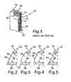
- FIGS. 2 to 5 Electrode shapes shown schematically possible.
- the FIGS. 2 to 5 show in this plan views of the electrodes in the stacking direction, in the Fig. 1 symbolized by the arrow 22.
- the electrodes are in the Fig. 2 to 5 shown only half and each to be understood as a mirror symmetry about the axes 24.
- a cell of the invention differs from that in Fig. 1 shown cell only by the shape of the electrodes and optionally by a matched to the electrode shape housing.
- the homogenization of the current density over the entire cell is achieved in all exemplary embodiments shown by the fact that the respective electrode 26 tapers away from a base edge 28.
- the base edge 28 corresponds to the edge 30 of the electrodes 12 Fig. 1 , ie the edge on which the connection tongue 14 is arranged.
- the exact shape of the electrode 26 can be further adapted to, for example, in cooperation with cooling systems, not shown here to provide an even better homogenization of the temperature distribution in the cell, or also to adapt the shape of the electrode 26 and thus the entire, the electrode 26 using cell to the space conditions of their place of use.
- cells shaped in this way are particularly suitable for use in motor vehicle technology, in particular for plug-in hybrids, range-extender battery vehicles and also purely electric vehicles.
- the electrodes 26 shown each have one of the base edge 28 opposite and parallel to this further edge 34.
- the edges 28 and 34 are connected by another straight edge 36, as in FIG Fig. 2 which results in a total trapezoidal shape 26.
- the side edges 38, 40 disposed between the base edge 28 and the further edge 34 may also be curved, as in FIGS FIGS. 4 and 5 shown. Both concave and convex curvatures are possible.
- a further edge running parallel to the base edge 28 is also completely dispensed with. This embodiment is in Fig. 3 shown.
- the end points 40 of the base edge 28 are connected here via a single curved edge 42, which preferably follows the curve of a conic. For the entire electrode 26 thus results in the shape of a circular or elliptical segment, or a cut paraboloid.
Landscapes
- General Chemical & Material Sciences (AREA)
- Chemical & Material Sciences (AREA)
- Chemical Kinetics & Catalysis (AREA)
- Electrochemistry (AREA)
- Engineering & Computer Science (AREA)
- Manufacturing & Machinery (AREA)
- Aviation & Aerospace Engineering (AREA)
- Life Sciences & Earth Sciences (AREA)
- Sustainable Development (AREA)
- Sustainable Energy (AREA)
- Connection Of Batteries Or Terminals (AREA)
- Secondary Cells (AREA)
- Battery Electrode And Active Subsutance (AREA)
Description
- Die Erfindung betrifft einen Kraftwagen mit einer elektrochemischen Zelle.
- Aufgrund der hohen Packungsdichte von Komponenten moderner Kraftwagen gewinnt die optimale Ausnutzung des zur Verfügung stehenden Bauraums zunehmend an Bedeutung. Dies ist bei batteriebetriebenen Elektrofahrzeugen von besonderer Wichtigkeit, da solche Kraftwagen eine große Anzahl von Batterien für ihren Betrieb benötigen.
- Aufgrund ihrer hohen Energiedichte werden zunehmend Lithiumionenakkumulatoren zur Stromversorgung von Kraftwagen eingesetzt. Solche Akkumulatoren sind meist in Form von sogenannten Stapelzellen mit einer Mehrzahl von plattenförmigen Elektroden ausgebildet.
- Üblicherweise sind die Elektroden solcher Stapelzellen rechteckig geformt und in deckungsgleicher Anordnung übereinander gestapelt. Der Stapel besteht dabei aus einer abwechselnden Abfolge von Anoden und Kathoden, wobei alle Anoden und alle Kathoden mit einem jeweiligen gemeinsamen Abgriffspol der Zelle verbunden sind. Die Anschlüsse der einzelnen Elektroden sind dabei jeweils auf derselben Seite des Elektrodenstapels angeordnet.
- Eine derartige Stapelzelle ist beispielsweise in der
US 7 368 191 B2 beschrieben. - Aufgrund der rechteckigen Form der Elektroden besitzen bekannte Stapelzeiien insgesamt eine rechteckige Querschnittsfläche. Im Kraftwagen muss daher ein ebenfalls im Querschnitt rechteckiger Einbauraum für eine solche Stapelzelle zur Verfügung gestellt werden. Aufgrund dieser Anforderung ist die Zahl der möglichen Einbaupositionen für eine solche Batterie in einen Kraftwagen begrenzt. Meist steht lediglich in einem Motorraum des Kraftwagens hinreichender Bauraum zur Verfügung.
- Aus der
US 2004/0089487 A1 ist ferner eine Batterie zur Aufnahme in einer Reserveradmulde bekannt. Die Elektroden dieser Batterie weisen eine im Wesentlichen halbkreisförmige Kontur auf, um den vorhandenen Bauraum optimal auszunutzen. - Die
JP 2006 127 882 A - Aus der
JP 633 543 A - Die
JP 2006 040 716 A - Der vorliegenden Erfindung liegt somit die Aufgabe zugrunde, einen Kraftwagen der eingangs genannten Art so weiterzuentwickeln, dass der zur Verfügung stehende Bauraum für Batterien besser genutzt wird.
- Diese Aufgabe wird durch einen Kraftwagen mit den Merkmalen des Patentanspruchs 1 gelöst.
- In einem solchen Kraftwagen ist eine elektrochemische Zelle außerhalb eines Motorraums des Kraftwagens in einem Aufnahmeraum angeordnet, welcher eine sich in Richtung der Fahrzeughochachse verjüngende Querschnittsfläche aufweist. Um den Aufnahmeraum möglichst vollständig auszunutzen, ist eine Querschnittsfläche der elektrochemischen Zelle an die Querschnittsfläche des Aufnahmeraums angepasst. Mit anderen Worten verjüngt sich auch die Querschnittsfläche der elektrochemischen Zelle in ihrer Einbaulage in Richtung der Fahrzeughochachse. Der im Kraftwagen zur Verfügung stehenden Bauraum wird somit besonders gut ausgenutzt. Ein Beispiel für einen solchen Aufnahmeraum ist ein Mitteltunnel des Kraftwagens. Gerade bei elektrischen angetriebenen Kraftwagen, welche keine Kardanwelle und keinen Abgasstrang aufweisen, kann der Mitteltunnel zur Aufnahme anderer Komponenten des Kraftwagens Verwendung finden. Aufgrund der Verjüngung der Querschnittsfläche der elektrochemischen Zelle ist diese besonders gut an den Querschnitt des Mitteltunnels angepasst, der sich in Fahrzeughochrichtung verjüngt. So kann nahezu der vollständige zur Verfügung stehenden Raum im Mitteltunnel zur Aufnahme von elektrochemischen Zellen genutzt werden. Bei elektrischen betriebenen Fahrzeugen mit einer Vielzahl von relativ schweren elektrochemischen Zellen wird durch die Unterbringung von elektrochemischen Zellen im Mitteltunnel zudem eine gute Gewichtsverteilung des Kraftwagens erreicht, was sich unmittelbar positiv auf dessen Fahreigenschaften auswirkt.
- Die elektrochemische Zelle selbst weist einen Elektrodenstapel aus wenigstens zwei Elektroden in paralleler Anordnung auf. Es handelt sich also um eine Stapelzelle. Die Elektroden sind so ausgebildet, dass eine Querschnittsfläche der Elektroden mit zunehmenden Abstand von einem Anschluss abnimmt, über welchen die jeweilige Elektrode mit einem zugeordneten Abgriffspol der Zelle verbunden ist. Dies kann erreicht werden, indem sich die Elektrode vom Anschluss weg keilförmig verjüngt. Hierdurch werden besonders gute elektrochemische Eigenschaften der Batterie erhalten.
- Aufgrund des inneren Widerstands der Elektrode treten nämlich pro Flächenelement der Elektrode umso mehr Ladungsträger in den Elektrolyten über, je näher das betrachtete Flächenelement am Anschluss der Elektrode angeordnet ist. Durch diese Inhomogenität des Stromflusses über die Elektrodenfläche hinweg kommt es zu einer inhomogenen thermischen Belastung der Zelle. Dies führt zu einer Rückkopplung, da sowohl der Widerstand der Elektrode selbst als auch der Durchtrittswiderstand von der Elektrode in den Elektrolyten mit steigender Temperatur sinkt. Dadurch erhöht sich die Stromflussdichte in Anschlussnähe noch zusätzlich, bis ein Gleichgewicht eingestellt ist. Durch die stark inhomogene Strom- und Temperaturverteilung kommt es oftmals zu einer vorzeitigen Alterung der elektrochemischen Zelle, was gerade bei Hochleistungsakkumulatoren im Automobilbereich zum vorzeitigen Austausch von Zellen oder Batteriesystemen führen kann und damit hohe Kosten beim Hersteller verursacht.
- Da die beschriebene Elektrode im anschlussnahen Bereich mit besonders hoher Stromdichte eine besonders große Querschnittsfläche aufweist, ist der innere Widerstand der Elektrode dort besonders klein, wodurch nur geringe thermische Belastungen auftreten. Neben der sehr guten Ausnutzung des Einbauraums wird also gleichzeitig eine besonders gute Haltbarkeit der elektrochemischen Zelle erreicht.
- Alternativ oder zusätzlich kann sich die Elektrode von einer anschlussseitigen Basiskante weg senkrecht zur Stapelrichtung der Elektroden verschmälern. Damit steht in unmittelbarer Nähe des Anschlusses - also im Bereich der höchsten Flächenstromdichte - eine entsprechend größere Durchtrittsfläche für Ladungsträger aus der Elektrode in den Elektrolyten bzw. umgekehrt zur Verfügung. Mit zunehmenden Abstand zum Anschluss nimmt diese Durchtrittsfläche ab, wobei sich aufgrund des ebenfalls abnehmenden Ladungsträgerdurchtritts eine im Wesentlichen homogene Flächenstromdichte über die gesamte Elektrode einstellt. Beschädigungen und Verschleißerscheinungen aufgrund von Inhomogenitäten der Flächenstromdichte und damit unterschiedlichen Temperaturen innerhalb der Zelle, wie sie bei aus dem Stand der Technik bekannten Stapelzellen mit rechteckigen Querschnitt auftreten, werden so vermieden.
- In der Einbaulage der elektrochemischen Zelle im Kraftwagen verläuft in diesem Fall die Stapelrichtung der Elektroden senkrecht zur sich verjüngenden Querschnittsfläche des Einbauraums. Der Anschluss der Elektroden befindet sich auf der in Fahrzeughochrichtung unteren Seite der Elektroden. Die Anpassung der Querschnittsfläche der elektrochemischen Zelle an die Form des Einbauraums wird also durch die Form der Elektroden erzielt.
- Bevorzugt ist die Elektrode spiegelsymmetrisch bezüglich einer Mittelsenkrechten auf die Basiskante ausgebildet. Ein Gradient bezüglich der zur Verfügung stehenden Durchtrittsfläche und des inneren Widerstandes tritt somit nur in Richtung vom Anschluss der Elektrode weg senkrecht zur Stapelrichtung auf. Durch die Formgebung der Elektrode werden also keine zusätzlichen Asymmetrien eingeführt, welche wiederum zu Inhomogenitäten in der Flächenstromdichte führen könnten.
- In einer ersten Ausführungsvariante weist die Elektrode eine weitere zur Basiskante parallele Kante auf. Im einfachsten Fall kann eine derartige Elektrode trapezoid ausgebildet sein. Je nach der Gesamtform der Zelle, die gegebenenfalls weitere Einflüsse auf die Homogenität des Stromflusses haben kann, kann die Elektrode auch von der trapezoiden Rechteckform abweichen. In dieser Ausführungsform der Erfindung sind die Seitenkanten der Elektrode, welche die Basiskante und die weitere Kante verbinden, gekrümmt ausgeführt. Alternativ hierzu wird auch auf die der Basiskante gegenüberliegende Kante verzichtet, wobei die Endpunkte der Basiskante in dieser Ausführungsform über eine gekrümmte Kante in Form eines Kegelschnittes verbunden sind. Die Elektrode erhält somit im einfachsten Fall die Form eines Kreissegmentes oder eines Ellipsensegmentes, kann aber auch paraboloid oder dergleichen ausgebildet sein.
- Auf der Seite der Basiskante jeder Elektrode ist weiterhin bevorzugterweise eine Anschlusszunge zum Verbinden der Elektrode mit dem zugeordneten Abgriffspol der elektrochemischen Zelle angeordnet. Da die Basiskante den breitesten Bereich der Elektrode darstellt, steht somit im Bereich des höchsten Ladungsträgerdurchtritts zwischen Elektrode und Elektrolyten die größte Elektrodenfläche zur Verfügung.
- Um weitere Inhomogenitäten im Stromfluss und in der Wärmeentwicklung, die aus der Relativlage der Elektroden im Stapel zueinander resultieren können, zu vermeiden, sind die Elektroden bevorzugt deckungsgleich im Elektrodenstapel angeordnet. Damit befinden sich auch die Basiskanten und damit die Anschlusszungen der Elektroden auf derselben Seite des Elektrodenstapels, so dass die interne Verbindung der Elektroden des Elektrodenstapels mit den Abgriffspolen der elektrochemischen Zelle besonders einfach ist.
- Im Folgenden soll die Erfindung und ihre Ausführungsformen anhand der Zeichnung näher erläutert werden. Hierbei zeigen:
- Fig. 1
- eine teilweise angeschnittene Ansicht einer Stapelzelle nach dem Stand der Technik; und
- Fig. 2-5
- unterschiedliche Ausführungsformen von Elektroden für eine elektrochemische Zelle eines erfindungsgemäßen Kraftwagens.
- Eine im Ganzen mit 10 bezeichnete, aus dem Stand der Technik bekannte prismatische Stapelzelle umfasst einen Stapel von Elektroden 12, welche über Anschlusszungen 14, die der Übersichtlichkeit halber nicht alle bezeichnet sind, mit jeweils zugeordneten Abgriffspolen 16, 18 der Zelle 10 verbunden sind. Die Elektroden 12 sind in einem Zellengehäuse 20 angeordnet und werden von einem Elektrolyten umspült. Bei aus dem Stand der Technik bekannten Stapelzellen sind die Elektroden 12 rechteckig ausgeführt.
- Da das Material der Elektroden 12 selbst einen nicht vernachlässigbaren Innenwiderstand aufweist, ist bei derartigen Zellen die Stromdichte zwischen Elektrode 12 und Elektrolyten abhängig vom Abstand eines betrachteten Flächenelementes von der Anschlusszunge 14. Je weiter das betrachtete Flächenelement von der Anschlusszunge 14 entfernt ist, desto größer ist der Widerstand der Elektrode 12 zwischen Anschlusszunge 14 und dem Flächenelement. Der Ladungsträgerdurchtritt zwischen Elektrode 12 und Elektrolyten ist daher im Nahbereich der Anschlusszunge 14 am höchsten und nimmt von dort aus kontinuierlich ab. Dadurch kommt es zu einer ungleichmäßigen thermischen Belastung der Zelle 10, da die Wärmeentwicklung an den Elektroden 12 proportional zum Stromfluss in den Elektrolyten ist. Im Bereich der Anschlusszungen 14 entsteht also am meisten Wärme. Dadurch sinkt der Widerstand der Elektrode 12 im Nahbereich der Anschlusszungen 14 weiter ab, wodurch sich der Stromfluss und damit die Wärmeentwicklung weiter erhöhen, bis sich schließlich ein Gleichgewicht einstellt. Aufgrund der inhomogenen Temperaturverteilung in der Zelle 10 kommt es zu vorzeitigem Verschleiß der Zelle 10 und letztendlich zu ihrem Versagen.
- Um die Lebensdauer derartiger Zellen zu erhöhen, ist es also wünschenswert, den Stromfluss innerhalb der Zelle möglichst homogen zu gestalten. Dies ist mit den in den
Figuren 2 bis 5 schematisch dargestellten Elektrodenformen möglich. DieFiguren 2 bis 5 zeigen hierbei Draufsichten auf die Elektroden in Stapelrichtung, die in derFig. 1 durch den Pfeil 22 symbolisiert wird. Die Elektroden sind dabei in denFig. 2 bis 5 nur zur Hälfte dargestellt und jeweils als spiegelsymmetrisch um die Achsen 24 zu verstehen. Eine erfindungsgemäße Zelle unterscheidet sich von der inFig. 1 gezeigten Zelle lediglich durch die Formgebung der Elektroden und gegebenenfalls durch ein an die Elektrodenform angepasstes Gehäuse. - Die Homogenisierung der Stromdichte über die ganze Zelle hinweg wird in allen gezeigten Ausführungsbeispielen dadurch erreicht, dass sich die jeweilige Elektrode 26 von einer Basiskante 28 weg verjüngt. Die Basiskante 28 entspricht dabei der Kante 30 der Elektroden 12 aus
Fig. 1 , also derjenigen Kante, an der die Anschlusszunge 14 angeordnet ist. - Je näher ein Flächenelement der Elektrode 26 an der Basiskante 28 angeordnet ist, desto geringer ist sein Abstand zu einer in den
Fig. 2 bis 5 nicht dargestellten Anschlusszunge. Um dem bereits oben erläuterten, durch den Innenwiderstand der Elektrode 26 bedingten Gradienten des Ladungsträgerdurchtritts von der Elektrode 26 in den Elektrolyten entgegenzuwirken, verjüngen sich die in denFig. 2 bis 5 gezeigten Elektroden also von der Basiskante 28 weg. Mit anderen Worten ist in Bereichen mit hohem Ladungsträgerdurchtritt die Breite d1 der Elektroden 26 größer als die Breite d2 in Bereichen der Elektrode mit geringem Ladungsträgerdurchtritt in den Elektrolyten. Damit wird die Flächenstromdichte über die Oberfläche 32 der Elektrode 26 homogenisiert. Aufgrund der nun gleichmäßigen Flächenstromdichte ist auch die durch den Stromfluss und die Elektrodenreaktion bedingte Wärmeentwicklung über die gesamte Oberfläche 32 der Elektrode 26 im Wesentlichen konstant. Ein Verschleiß durch inhomogene thermische Belastungen wird also vermieden. - Die genaue Form der Elektrode 26 kann dabei weiter angepasst werden, um beispielsweise in Zusammenwirkung mit hier nicht dargestellten Kühlsystemen für eine noch bessere Homogenisierung der Temperaturverteilung in der Zelle zu sorgen, oder auch um die Form der Elektrode 26 und damit der gesamten, die Elektrode 26 verwendenden Zelle, an die Bauraumgegebenheiten ihres Einsatzortes anzupassen. Durch das Sichverjüngen der Elektroden 26 von ihrer Basiskante 28 weg eignen sich derart geformte Zellen besonders gut zum Einsatz in der Kraftfahrzeugtechnik, insbesondere für Plugin-Hybride, Range-Extender-Batteriefahrzeuge und auch reine Elektrofahrzeuge. Zu den genannten Vorteilen aufgrund der homogeneren Stromflussverteilung in der Zelle kommt hier noch ein Bauraumvorteil. Aufgrund der Formgebung der Elektroden eignen sich derartige Zellen nämlich besonders gut zur Montage in einem Mitteltunnel eines Kraftwagens. Damit können sie besonders bauraumsparend untergebracht werden.
- Die in den
Figuren 2, 4 und 5 gezeigten Elektroden 26 weisen jeweils eine der Basiskante 28 gegenüberliegende und zu dieser parallele weitere Kante 34 auf. Im einfachsten Fall sind die Kanten 28 und 34 durch eine weitere gerade Kante 36 verbunden, wie inFig. 2 gezeigt, wodurch sich eine insgesamt trapezoide Form 26 ergibt. Alternativ können die zwischen Basiskante 28 und weiterer Kante 34 angeordneten Seitenkanten 38, 40 auch gekrümmt sein, wie in denFiguren 4 und 5 dargestellt. Es sind dabei sowohl konkave als auch konvexe Krümmungen möglich. Weiter alternativ wird auch vollständig auf eine zur Basiskante 28 parallel verlaufende weitere Kante verzichtet. Diese Ausführungsform ist inFig. 3 gezeigt. Die Endpunkte 40 der Basiskante 28 sind hier über eine einzelne gekrümmte Kante 42 verbunden, welche bevorzugt der Kurve eines Kegelschnittes folgt. Für die gesamte Elektrode 26 ergibt sich damit die Form eines Kreis- oder Ellipsensegmentes, bzw. eines geschnittenen Paraboloids.
Claims (9)
- Kraftwagen mit einer elektrochemischen Zelle (10), welche einen Elektrodenstapel aus wenigstens zwei Elektroden (26) in paralleler Anordnung aufweist, wobei die elektrochemische Zelle (10) außerhalb eines Motorraums des Kraftwagens in einem Aufnahmeraum des Kraftwagens angeordnet und eine Querschnittfläche der elektrochemischen Zelle 10 an die Querschnittsflächen des Aufnahmeraums angepasst ist,
dadurch gekennzeichnet, dass
der Aufnahmeraum eine sich in Richtung der Fahrzeughochachse verjüngende Querschnittsfläche aufweist, und eine Querschnittsfläche der Elektroden (26) mit zunehmendem Abstand von einem Anschluss, über welchen die jeweilige Elektrode (26) mit einem zugeordneten Abgriffspol (16,18) der Zelle (10) verbunden ist, abnimmt. - Kraftwagen nach Anspruch 1,
dadurch gekennzeichnet, dass
die Elektrode (26) sich von einer Basiskante (28) weg senkrecht zur Stapelrichtung (22) der Elektroden (26) verjüngt. - Kraftwagen nach Anspruch 1 oder 2,
dadurch gekennzeichnet, dass
die Elektrode (26) spiegelsymmetrisch bezüglich einer Mittelsenkrechten auf die Basiskante (28) ausgebildet ist. - Kraftwagen nach Anspruch 2 oder 3,
dadurch gekennzeichnet, dass
die Elektrode (26) eine weitere, zur Basiskante (28) parallele Kante (34) aufweist. - Kraftwagen nach Anspruch 4,
dadurch gekennzeichnet, dass
die Elektrode trapezoid ausgebildet ist. - Kraftwagen nach Anspruch 4,
dadurch gekennzeichnet, dass
Seitenkanten der Elektrode (26), welche die Basiskante (28) und die weitere Kante (34) verbinden, gekrümmt sind. - Kraftwagen nach Anspruch 2 oder 3,
dadurch gekennzeichnet, dass
die Endpunkte (40) der Basiskante (28) über eine gekrümmte Kante (42) verbunden sind, deren Verlauf einem Kegelschnitt folgt. - Kraftwagen nach einem der Ansprüche 2 bis 7,
dadurch gekennzeichnet, dass
jede Elektrode auf Seite der Basiskante (28) eine Anschlusszunge (14) zum Verbinden der Elektrode (26) mit dem zugeordneten Abgriffspol (16,18) der elektrochemischen Zelle (10) aufweist. - Kraftwagen nach einem der Ansprüche 1 bis 8,
dadurch gekennzeichnet, dass
die Elektroden (26) deckungsgleich im Elektrodenstapel angeordnet sind.
Applications Claiming Priority (2)
| Application Number | Priority Date | Filing Date | Title |
|---|---|---|---|
| DE102009038422A DE102009038422B4 (de) | 2009-08-21 | 2009-08-21 | Kraftwagen |
| PCT/EP2010/004785 WO2011020562A1 (de) | 2009-08-21 | 2010-08-04 | Kraftwagen mit einer elektrochemischen zelle |
Publications (2)
| Publication Number | Publication Date |
|---|---|
| EP2467888A1 EP2467888A1 (de) | 2012-06-27 |
| EP2467888B1 true EP2467888B1 (de) | 2013-10-16 |
Family
ID=42983638
Family Applications (1)
| Application Number | Title | Priority Date | Filing Date |
|---|---|---|---|
| EP10742756.9A Not-in-force EP2467888B1 (de) | 2009-08-21 | 2010-08-04 | Kraftwagen mit einer elektrochemischen zelle |
Country Status (5)
| Country | Link |
|---|---|
| US (1) | US8485297B2 (de) |
| EP (1) | EP2467888B1 (de) |
| CN (1) | CN102549828B (de) |
| DE (1) | DE102009038422B4 (de) |
| WO (1) | WO2011020562A1 (de) |
Families Citing this family (4)
| Publication number | Priority date | Publication date | Assignee | Title |
|---|---|---|---|---|
| DE102009038422B4 (de) | 2009-08-21 | 2013-08-22 | Audi Ag | Kraftwagen |
| DE102011077590A1 (de) * | 2011-06-16 | 2012-12-20 | Bayerische Motoren Werke Aktiengesellschaft | Fahrzeug, insbesondere Hybridfahrzeug |
| JP5983058B2 (ja) * | 2012-06-05 | 2016-08-31 | スズキ株式会社 | 電気自動車のバッテリパック搭載構造 |
| CN106099154B (zh) * | 2016-08-25 | 2018-11-06 | 中国科学院金属研究所 | 一种连续化电池组结构装置 |
Family Cites Families (12)
| Publication number | Priority date | Publication date | Assignee | Title |
|---|---|---|---|---|
| JPH06333543A (ja) * | 1993-05-20 | 1994-12-02 | Sony Corp | 蓄電池 |
| DE9320701U1 (de) * | 1993-11-12 | 1995-01-19 | Adam Opel AG, 65428 Rüsselsheim | Kraftfahrzeug mit einer Batterie |
| US6230833B1 (en) * | 1999-07-06 | 2001-05-15 | Visteon Global Technologies, Inc. | Storage battery tuning of engine air intake system |
| DE19944186A1 (de) * | 1999-09-15 | 2001-03-29 | Xcellsis Gmbh | Vorrichtung zum Erwärmen und/oder Umsetzen wenigstens eines Mediums |
| JP3777981B2 (ja) * | 2000-04-13 | 2006-05-24 | トヨタ自動車株式会社 | 車両用電源装置 |
| US7368191B2 (en) * | 2001-07-25 | 2008-05-06 | Biosource, Inc. | Electrode array for use in electrochemical cells |
| US6854543B2 (en) * | 2002-11-12 | 2005-02-15 | Daimlerchrysler Corporation | Semicircular battery for a vehicle |
| JP4121898B2 (ja) * | 2003-05-21 | 2008-07-23 | 本田技研工業株式会社 | 高圧電装部品の車載構造 |
| JP2006040716A (ja) * | 2004-07-27 | 2006-02-09 | Nissan Motor Co Ltd | 燃料電池スタック |
| JP2006127882A (ja) * | 2004-10-28 | 2006-05-18 | Nissan Motor Co Ltd | 薄型電池および組電池 |
| KR100905393B1 (ko) * | 2005-01-21 | 2009-06-30 | 주식회사 엘지화학 | 이차전지 모듈 |
| DE102009038422B4 (de) | 2009-08-21 | 2013-08-22 | Audi Ag | Kraftwagen |
-
2009
- 2009-08-21 DE DE102009038422A patent/DE102009038422B4/de not_active Expired - Fee Related
-
2010
- 2010-08-04 EP EP10742756.9A patent/EP2467888B1/de not_active Not-in-force
- 2010-08-04 CN CN201080037149.7A patent/CN102549828B/zh not_active Expired - Fee Related
- 2010-08-04 WO PCT/EP2010/004785 patent/WO2011020562A1/de not_active Ceased
- 2010-08-04 US US13/391,215 patent/US8485297B2/en not_active Expired - Fee Related
Also Published As
| Publication number | Publication date |
|---|---|
| US20120186891A1 (en) | 2012-07-26 |
| CN102549828A (zh) | 2012-07-04 |
| DE102009038422B4 (de) | 2013-08-22 |
| DE102009038422A8 (de) | 2011-06-01 |
| EP2467888A1 (de) | 2012-06-27 |
| DE102009038422A1 (de) | 2011-03-03 |
| WO2011020562A1 (de) | 2011-02-24 |
| US8485297B2 (en) | 2013-07-16 |
| CN102549828B (zh) | 2014-07-02 |
Similar Documents
| Publication | Publication Date | Title |
|---|---|---|
| DE102014106954B4 (de) | Vorrichtung zum Heizen und Kühlen eines Batteriepakets sowie Fahrzeugantriebsbatteriebaugruppe | |
| DE102009035492A1 (de) | Batterie mit einer Vielzahl von plattenförmigen Batteriezellen | |
| DE102008034869A1 (de) | Batterie mit mehreren einen Zellenverbund bildenden Batteriezellen | |
| DE102009035463A1 (de) | Batterie mit einer Vielzahl von plattenförmigen Batteriezellen | |
| DE102010013024A1 (de) | Batterie aus einer Vielzahl von Batterieeinzelzellen | |
| DE102007063185A1 (de) | Batterie | |
| DE102021125167A1 (de) | Batteriemodul | |
| DE102006015566A1 (de) | Flexibler Polverbinder | |
| WO2023110543A1 (de) | Elektrische energiespeichereinrichtung mit terminaltemperierung und gaskanal | |
| EP1306911A2 (de) | Dicht verschlossener Akkumulator | |
| DE102009038422B4 (de) | Kraftwagen | |
| WO2012072437A1 (de) | Akkumulatorzelle mit beschichtetem terminal | |
| DE102013016616A1 (de) | Hochvoltbatterie mit einer Vielzahl von Batterieeinzelzellen | |
| DE102013016790A1 (de) | Batterieeinzelzelle in prismatischer Form | |
| DE102018105044A1 (de) | Akkumulator, insbesondere für ein Kraftfahrzeug und Kraftfahrzeug umfassend einen solchen Akkumulator | |
| DE102022104370A1 (de) | Batteriezelleneinheit und Energiespeicher für ein Kraftfahrzeug | |
| DE102021002328A1 (de) | Elektrischer Energiespeicher für ein Fahrzeug | |
| AT526109B1 (de) | Pouch-Zelle und Batteriepack | |
| DE102020007733A1 (de) | Batterie aus einem Stapel von Batterieeinzelzellen | |
| DE102009014116B3 (de) | Batteriezellenverbinder und Batterie | |
| DE102013208140A1 (de) | Batteriezelle mit einem mindestens einen Einschnitt aufweisenden Elektrodenwickel | |
| DE102010009731A1 (de) | Batterie für einen Kraftwagen | |
| DE102024003715A1 (de) | Elektrischer Energiespeicher und Fahrzeug | |
| DE102024000259A1 (de) | Zellgehäuse, Batteriezelle, Batteriemodul und Batterie | |
| DE102023121001A1 (de) | Ausgeglichene stromkollektorplatte |
Legal Events
| Date | Code | Title | Description |
|---|---|---|---|
| PUAI | Public reference made under article 153(3) epc to a published international application that has entered the european phase |
Free format text: ORIGINAL CODE: 0009012 |
|
| 17P | Request for examination filed |
Effective date: 20120321 |
|
| AK | Designated contracting states |
Kind code of ref document: A1 Designated state(s): AL AT BE BG CH CY CZ DE DK EE ES FI FR GB GR HR HU IE IS IT LI LT LU LV MC MK MT NL NO PL PT RO SE SI SK SM TR |
|
| DAX | Request for extension of the european patent (deleted) | ||
| GRAP | Despatch of communication of intention to grant a patent |
Free format text: ORIGINAL CODE: EPIDOSNIGR1 |
|
| INTG | Intention to grant announced |
Effective date: 20130418 |
|
| GRAS | Grant fee paid |
Free format text: ORIGINAL CODE: EPIDOSNIGR3 |
|
| GRAA | (expected) grant |
Free format text: ORIGINAL CODE: 0009210 |
|
| AK | Designated contracting states |
Kind code of ref document: B1 Designated state(s): AL AT BE BG CH CY CZ DE DK EE ES FI FR GB GR HR HU IE IS IT LI LT LU LV MC MK MT NL NO PL PT RO SE SI SK SM TR |
|
| REG | Reference to a national code |
Ref country code: GB Ref legal event code: FG4D Free format text: NOT ENGLISH |
|
| REG | Reference to a national code |
Ref country code: CH Ref legal event code: EP |
|
| REG | Reference to a national code |
Ref country code: IE Ref legal event code: FG4D Free format text: LANGUAGE OF EP DOCUMENT: GERMAN |
|
| REG | Reference to a national code |
Ref country code: AT Ref legal event code: REF Ref document number: 636875 Country of ref document: AT Kind code of ref document: T Effective date: 20131115 |
|
| REG | Reference to a national code |
Ref country code: DE Ref legal event code: R096 Ref document number: 502010005090 Country of ref document: DE Effective date: 20131212 |
|
| REG | Reference to a national code |
Ref country code: NL Ref legal event code: VDEP Effective date: 20131016 |
|
| REG | Reference to a national code |
Ref country code: LT Ref legal event code: MG4D |
|
| PG25 | Lapsed in a contracting state [announced via postgrant information from national office to epo] |
Ref country code: IS Free format text: LAPSE BECAUSE OF FAILURE TO SUBMIT A TRANSLATION OF THE DESCRIPTION OR TO PAY THE FEE WITHIN THE PRESCRIBED TIME-LIMIT Effective date: 20140216 Ref country code: SE Free format text: LAPSE BECAUSE OF FAILURE TO SUBMIT A TRANSLATION OF THE DESCRIPTION OR TO PAY THE FEE WITHIN THE PRESCRIBED TIME-LIMIT Effective date: 20131016 Ref country code: HR Free format text: LAPSE BECAUSE OF FAILURE TO SUBMIT A TRANSLATION OF THE DESCRIPTION OR TO PAY THE FEE WITHIN THE PRESCRIBED TIME-LIMIT Effective date: 20131016 Ref country code: FI Free format text: LAPSE BECAUSE OF FAILURE TO SUBMIT A TRANSLATION OF THE DESCRIPTION OR TO PAY THE FEE WITHIN THE PRESCRIBED TIME-LIMIT Effective date: 20131016 Ref country code: LT Free format text: LAPSE BECAUSE OF FAILURE TO SUBMIT A TRANSLATION OF THE DESCRIPTION OR TO PAY THE FEE WITHIN THE PRESCRIBED TIME-LIMIT Effective date: 20131016 Ref country code: NO Free format text: LAPSE BECAUSE OF FAILURE TO SUBMIT A TRANSLATION OF THE DESCRIPTION OR TO PAY THE FEE WITHIN THE PRESCRIBED TIME-LIMIT Effective date: 20140116 Ref country code: NL Free format text: LAPSE BECAUSE OF FAILURE TO SUBMIT A TRANSLATION OF THE DESCRIPTION OR TO PAY THE FEE WITHIN THE PRESCRIBED TIME-LIMIT Effective date: 20131016 |
|
| PG25 | Lapsed in a contracting state [announced via postgrant information from national office to epo] |
Ref country code: ES Free format text: LAPSE BECAUSE OF FAILURE TO SUBMIT A TRANSLATION OF THE DESCRIPTION OR TO PAY THE FEE WITHIN THE PRESCRIBED TIME-LIMIT Effective date: 20131016 Ref country code: LV Free format text: LAPSE BECAUSE OF FAILURE TO SUBMIT A TRANSLATION OF THE DESCRIPTION OR TO PAY THE FEE WITHIN THE PRESCRIBED TIME-LIMIT Effective date: 20131016 Ref country code: CY Free format text: LAPSE BECAUSE OF FAILURE TO SUBMIT A TRANSLATION OF THE DESCRIPTION OR TO PAY THE FEE WITHIN THE PRESCRIBED TIME-LIMIT Effective date: 20131016 |
|
| PG25 | Lapsed in a contracting state [announced via postgrant information from national office to epo] |
Ref country code: PT Free format text: LAPSE BECAUSE OF FAILURE TO SUBMIT A TRANSLATION OF THE DESCRIPTION OR TO PAY THE FEE WITHIN THE PRESCRIBED TIME-LIMIT Effective date: 20140217 |
|
| REG | Reference to a national code |
Ref country code: DE Ref legal event code: R097 Ref document number: 502010005090 Country of ref document: DE |
|
| PG25 | Lapsed in a contracting state [announced via postgrant information from national office to epo] |
Ref country code: EE Free format text: LAPSE BECAUSE OF FAILURE TO SUBMIT A TRANSLATION OF THE DESCRIPTION OR TO PAY THE FEE WITHIN THE PRESCRIBED TIME-LIMIT Effective date: 20131016 |
|
| PLBE | No opposition filed within time limit |
Free format text: ORIGINAL CODE: 0009261 |
|
| STAA | Information on the status of an ep patent application or granted ep patent |
Free format text: STATUS: NO OPPOSITION FILED WITHIN TIME LIMIT |
|
| PG25 | Lapsed in a contracting state [announced via postgrant information from national office to epo] |
Ref country code: RO Free format text: LAPSE BECAUSE OF FAILURE TO SUBMIT A TRANSLATION OF THE DESCRIPTION OR TO PAY THE FEE WITHIN THE PRESCRIBED TIME-LIMIT Effective date: 20131016 Ref country code: CZ Free format text: LAPSE BECAUSE OF FAILURE TO SUBMIT A TRANSLATION OF THE DESCRIPTION OR TO PAY THE FEE WITHIN THE PRESCRIBED TIME-LIMIT Effective date: 20131016 Ref country code: IT Free format text: LAPSE BECAUSE OF FAILURE TO SUBMIT A TRANSLATION OF THE DESCRIPTION OR TO PAY THE FEE WITHIN THE PRESCRIBED TIME-LIMIT Effective date: 20131016 Ref country code: PL Free format text: LAPSE BECAUSE OF FAILURE TO SUBMIT A TRANSLATION OF THE DESCRIPTION OR TO PAY THE FEE WITHIN THE PRESCRIBED TIME-LIMIT Effective date: 20131016 Ref country code: SK Free format text: LAPSE BECAUSE OF FAILURE TO SUBMIT A TRANSLATION OF THE DESCRIPTION OR TO PAY THE FEE WITHIN THE PRESCRIBED TIME-LIMIT Effective date: 20131016 |
|
| 26N | No opposition filed |
Effective date: 20140717 |
|
| PG25 | Lapsed in a contracting state [announced via postgrant information from national office to epo] |
Ref country code: DK Free format text: LAPSE BECAUSE OF FAILURE TO SUBMIT A TRANSLATION OF THE DESCRIPTION OR TO PAY THE FEE WITHIN THE PRESCRIBED TIME-LIMIT Effective date: 20131016 |
|
| REG | Reference to a national code |
Ref country code: DE Ref legal event code: R097 Ref document number: 502010005090 Country of ref document: DE Effective date: 20140717 |
|
| PG25 | Lapsed in a contracting state [announced via postgrant information from national office to epo] |
Ref country code: SI Free format text: LAPSE BECAUSE OF FAILURE TO SUBMIT A TRANSLATION OF THE DESCRIPTION OR TO PAY THE FEE WITHIN THE PRESCRIBED TIME-LIMIT Effective date: 20131016 |
|
| PG25 | Lapsed in a contracting state [announced via postgrant information from national office to epo] |
Ref country code: MC Free format text: LAPSE BECAUSE OF FAILURE TO SUBMIT A TRANSLATION OF THE DESCRIPTION OR TO PAY THE FEE WITHIN THE PRESCRIBED TIME-LIMIT Effective date: 20131016 Ref country code: LU Free format text: LAPSE BECAUSE OF FAILURE TO SUBMIT A TRANSLATION OF THE DESCRIPTION OR TO PAY THE FEE WITHIN THE PRESCRIBED TIME-LIMIT Effective date: 20140804 |
|
| REG | Reference to a national code |
Ref country code: CH Ref legal event code: PL |
|
| PG25 | Lapsed in a contracting state [announced via postgrant information from national office to epo] |
Ref country code: LI Free format text: LAPSE BECAUSE OF NON-PAYMENT OF DUE FEES Effective date: 20140831 Ref country code: BE Free format text: LAPSE BECAUSE OF NON-PAYMENT OF DUE FEES Effective date: 20140831 Ref country code: CH Free format text: LAPSE BECAUSE OF NON-PAYMENT OF DUE FEES Effective date: 20140831 |
|
| REG | Reference to a national code |
Ref country code: IE Ref legal event code: MM4A |
|
| PG25 | Lapsed in a contracting state [announced via postgrant information from national office to epo] |
Ref country code: IE Free format text: LAPSE BECAUSE OF NON-PAYMENT OF DUE FEES Effective date: 20140804 |
|
| PG25 | Lapsed in a contracting state [announced via postgrant information from national office to epo] |
Ref country code: SM Free format text: LAPSE BECAUSE OF FAILURE TO SUBMIT A TRANSLATION OF THE DESCRIPTION OR TO PAY THE FEE WITHIN THE PRESCRIBED TIME-LIMIT Effective date: 20131016 |
|
| PG25 | Lapsed in a contracting state [announced via postgrant information from national office to epo] |
Ref country code: GR Free format text: LAPSE BECAUSE OF FAILURE TO SUBMIT A TRANSLATION OF THE DESCRIPTION OR TO PAY THE FEE WITHIN THE PRESCRIBED TIME-LIMIT Effective date: 20140117 Ref country code: MT Free format text: LAPSE BECAUSE OF FAILURE TO SUBMIT A TRANSLATION OF THE DESCRIPTION OR TO PAY THE FEE WITHIN THE PRESCRIBED TIME-LIMIT Effective date: 20131016 Ref country code: BG Free format text: LAPSE BECAUSE OF FAILURE TO SUBMIT A TRANSLATION OF THE DESCRIPTION OR TO PAY THE FEE WITHIN THE PRESCRIBED TIME-LIMIT Effective date: 20131016 |
|
| PG25 | Lapsed in a contracting state [announced via postgrant information from national office to epo] |
Ref country code: HU Free format text: LAPSE BECAUSE OF FAILURE TO SUBMIT A TRANSLATION OF THE DESCRIPTION OR TO PAY THE FEE WITHIN THE PRESCRIBED TIME-LIMIT; INVALID AB INITIO Effective date: 20100804 Ref country code: TR Free format text: LAPSE BECAUSE OF FAILURE TO SUBMIT A TRANSLATION OF THE DESCRIPTION OR TO PAY THE FEE WITHIN THE PRESCRIBED TIME-LIMIT Effective date: 20131016 |
|
| REG | Reference to a national code |
Ref country code: FR Ref legal event code: PLFP Year of fee payment: 7 |
|
| REG | Reference to a national code |
Ref country code: AT Ref legal event code: MM01 Ref document number: 636875 Country of ref document: AT Kind code of ref document: T Effective date: 20150804 |
|
| PG25 | Lapsed in a contracting state [announced via postgrant information from national office to epo] |
Ref country code: AT Free format text: LAPSE BECAUSE OF NON-PAYMENT OF DUE FEES Effective date: 20150804 |
|
| REG | Reference to a national code |
Ref country code: FR Ref legal event code: PLFP Year of fee payment: 8 |
|
| PG25 | Lapsed in a contracting state [announced via postgrant information from national office to epo] |
Ref country code: MK Free format text: LAPSE BECAUSE OF FAILURE TO SUBMIT A TRANSLATION OF THE DESCRIPTION OR TO PAY THE FEE WITHIN THE PRESCRIBED TIME-LIMIT Effective date: 20131016 |
|
| REG | Reference to a national code |
Ref country code: FR Ref legal event code: PLFP Year of fee payment: 9 |
|
| PG25 | Lapsed in a contracting state [announced via postgrant information from national office to epo] |
Ref country code: AL Free format text: LAPSE BECAUSE OF FAILURE TO SUBMIT A TRANSLATION OF THE DESCRIPTION OR TO PAY THE FEE WITHIN THE PRESCRIBED TIME-LIMIT Effective date: 20131016 |
|
| REG | Reference to a national code |
Ref country code: DE Ref legal event code: R079 Ref document number: 502010005090 Country of ref document: DE Free format text: PREVIOUS MAIN CLASS: H01M0002100000 Ipc: H01M0050200000 |
|
| PGFP | Annual fee paid to national office [announced via postgrant information from national office to epo] |
Ref country code: FR Payment date: 20210820 Year of fee payment: 12 |
|
| PGFP | Annual fee paid to national office [announced via postgrant information from national office to epo] |
Ref country code: DE Payment date: 20210831 Year of fee payment: 12 Ref country code: GB Payment date: 20210823 Year of fee payment: 12 |
|
| REG | Reference to a national code |
Ref country code: DE Ref legal event code: R119 Ref document number: 502010005090 Country of ref document: DE |
|
| GBPC | Gb: european patent ceased through non-payment of renewal fee |
Effective date: 20220804 |
|
| PG25 | Lapsed in a contracting state [announced via postgrant information from national office to epo] |
Ref country code: FR Free format text: LAPSE BECAUSE OF NON-PAYMENT OF DUE FEES Effective date: 20220831 Ref country code: DE Free format text: LAPSE BECAUSE OF NON-PAYMENT OF DUE FEES Effective date: 20230301 |
|
| PG25 | Lapsed in a contracting state [announced via postgrant information from national office to epo] |
Ref country code: GB Free format text: LAPSE BECAUSE OF NON-PAYMENT OF DUE FEES Effective date: 20220804 |