EP2467660B1 - Temperatursteuerungssystem für eine flüssigkeit - Google Patents
Temperatursteuerungssystem für eine flüssigkeit Download PDFInfo
- Publication number
- EP2467660B1 EP2467660B1 EP10768815.2A EP10768815A EP2467660B1 EP 2467660 B1 EP2467660 B1 EP 2467660B1 EP 10768815 A EP10768815 A EP 10768815A EP 2467660 B1 EP2467660 B1 EP 2467660B1
- Authority
- EP
- European Patent Office
- Prior art keywords
- heat
- temperature control
- elements
- liquid
- segments
- Prior art date
- Legal status (The legal status is an assumption and is not a legal conclusion. Google has not performed a legal analysis and makes no representation as to the accuracy of the status listed.)
- Active
Links
- 239000007788 liquid Substances 0.000 title claims description 69
- 238000001816 cooling Methods 0.000 claims description 64
- 239000012530 fluid Substances 0.000 claims description 21
- 239000002826 coolant Substances 0.000 claims description 10
- 238000010521 absorption reaction Methods 0.000 claims description 8
- 235000013361 beverage Nutrition 0.000 claims description 8
- 230000017525 heat dissipation Effects 0.000 claims description 4
- WYTGDNHDOZPMIW-RCBQFDQVSA-N alstonine Natural products C1=CC2=C3C=CC=CC3=NC2=C2N1C[C@H]1[C@H](C)OC=C(C(=O)OC)[C@H]1C2 WYTGDNHDOZPMIW-RCBQFDQVSA-N 0.000 claims description 3
- 239000004020 conductor Substances 0.000 claims description 3
- 230000001105 regulatory effect Effects 0.000 claims description 3
- 238000010438 heat treatment Methods 0.000 description 20
- 238000004891 communication Methods 0.000 description 17
- XLYOFNOQVPJJNP-UHFFFAOYSA-N water Substances O XLYOFNOQVPJJNP-UHFFFAOYSA-N 0.000 description 11
- 239000003651 drinking water Substances 0.000 description 7
- 235000020188 drinking water Nutrition 0.000 description 5
- 238000009825 accumulation Methods 0.000 description 4
- 239000002184 metal Substances 0.000 description 4
- 229910052751 metal Inorganic materials 0.000 description 4
- 239000012809 cooling fluid Substances 0.000 description 3
- 239000000463 material Substances 0.000 description 3
- 238000005057 refrigeration Methods 0.000 description 3
- 235000012206 bottled water Nutrition 0.000 description 2
- 230000005465 channeling Effects 0.000 description 2
- 238000001914 filtration Methods 0.000 description 2
- 239000012782 phase change material Substances 0.000 description 2
- 239000007787 solid Substances 0.000 description 2
- RYGMFSIKBFXOCR-UHFFFAOYSA-N Copper Chemical compound [Cu] RYGMFSIKBFXOCR-UHFFFAOYSA-N 0.000 description 1
- AYFVYJQAPQTCCC-GBXIJSLDSA-N L-threonine Chemical compound C[C@@H](O)[C@H](N)C(O)=O AYFVYJQAPQTCCC-GBXIJSLDSA-N 0.000 description 1
- 230000005679 Peltier effect Effects 0.000 description 1
- 238000003491 array Methods 0.000 description 1
- 230000008602 contraction Effects 0.000 description 1
- 229910052802 copper Inorganic materials 0.000 description 1
- 239000010949 copper Substances 0.000 description 1
- 230000008878 coupling Effects 0.000 description 1
- 238000010168 coupling process Methods 0.000 description 1
- 238000005859 coupling reaction Methods 0.000 description 1
- 238000005265 energy consumption Methods 0.000 description 1
- 238000009434 installation Methods 0.000 description 1
- 230000001788 irregular Effects 0.000 description 1
- 230000007246 mechanism Effects 0.000 description 1
- 235000014214 soft drink Nutrition 0.000 description 1
Images


Classifications
-
- F—MECHANICAL ENGINEERING; LIGHTING; HEATING; WEAPONS; BLASTING
- F25—REFRIGERATION OR COOLING; COMBINED HEATING AND REFRIGERATION SYSTEMS; HEAT PUMP SYSTEMS; MANUFACTURE OR STORAGE OF ICE; LIQUEFACTION SOLIDIFICATION OF GASES
- F25D—REFRIGERATORS; COLD ROOMS; ICE-BOXES; COOLING OR FREEZING APPARATUS NOT OTHERWISE PROVIDED FOR
- F25D31/00—Other cooling or freezing apparatus
- F25D31/002—Liquid coolers, e.g. beverage cooler
-
- F—MECHANICAL ENGINEERING; LIGHTING; HEATING; WEAPONS; BLASTING
- F25—REFRIGERATION OR COOLING; COMBINED HEATING AND REFRIGERATION SYSTEMS; HEAT PUMP SYSTEMS; MANUFACTURE OR STORAGE OF ICE; LIQUEFACTION SOLIDIFICATION OF GASES
- F25B—REFRIGERATION MACHINES, PLANTS OR SYSTEMS; COMBINED HEATING AND REFRIGERATION SYSTEMS; HEAT PUMP SYSTEMS
- F25B21/00—Machines, plants or systems, using electric or magnetic effects
- F25B21/02—Machines, plants or systems, using electric or magnetic effects using Peltier effect; using Nernst-Ettinghausen effect
-
- F—MECHANICAL ENGINEERING; LIGHTING; HEATING; WEAPONS; BLASTING
- F25—REFRIGERATION OR COOLING; COMBINED HEATING AND REFRIGERATION SYSTEMS; HEAT PUMP SYSTEMS; MANUFACTURE OR STORAGE OF ICE; LIQUEFACTION SOLIDIFICATION OF GASES
- F25D—REFRIGERATORS; COLD ROOMS; ICE-BOXES; COOLING OR FREEZING APPARATUS NOT OTHERWISE PROVIDED FOR
- F25D29/00—Arrangement or mounting of control or safety devices
-
- F—MECHANICAL ENGINEERING; LIGHTING; HEATING; WEAPONS; BLASTING
- F25—REFRIGERATION OR COOLING; COMBINED HEATING AND REFRIGERATION SYSTEMS; HEAT PUMP SYSTEMS; MANUFACTURE OR STORAGE OF ICE; LIQUEFACTION SOLIDIFICATION OF GASES
- F25B—REFRIGERATION MACHINES, PLANTS OR SYSTEMS; COMBINED HEATING AND REFRIGERATION SYSTEMS; HEAT PUMP SYSTEMS
- F25B21/00—Machines, plants or systems, using electric or magnetic effects
- F25B21/02—Machines, plants or systems, using electric or magnetic effects using Peltier effect; using Nernst-Ettinghausen effect
- F25B21/04—Machines, plants or systems, using electric or magnetic effects using Peltier effect; using Nernst-Ettinghausen effect reversible
-
- F—MECHANICAL ENGINEERING; LIGHTING; HEATING; WEAPONS; BLASTING
- F25—REFRIGERATION OR COOLING; COMBINED HEATING AND REFRIGERATION SYSTEMS; HEAT PUMP SYSTEMS; MANUFACTURE OR STORAGE OF ICE; LIQUEFACTION SOLIDIFICATION OF GASES
- F25B—REFRIGERATION MACHINES, PLANTS OR SYSTEMS; COMBINED HEATING AND REFRIGERATION SYSTEMS; HEAT PUMP SYSTEMS
- F25B2321/00—Details of machines, plants or systems, using electric or magnetic effects
- F25B2321/02—Details of machines, plants or systems, using electric or magnetic effects using Peltier effects; using Nernst-Ettinghausen effects
- F25B2321/023—Mounting details thereof
-
- F—MECHANICAL ENGINEERING; LIGHTING; HEATING; WEAPONS; BLASTING
- F25—REFRIGERATION OR COOLING; COMBINED HEATING AND REFRIGERATION SYSTEMS; HEAT PUMP SYSTEMS; MANUFACTURE OR STORAGE OF ICE; LIQUEFACTION SOLIDIFICATION OF GASES
- F25B—REFRIGERATION MACHINES, PLANTS OR SYSTEMS; COMBINED HEATING AND REFRIGERATION SYSTEMS; HEAT PUMP SYSTEMS
- F25B2321/00—Details of machines, plants or systems, using electric or magnetic effects
- F25B2321/02—Details of machines, plants or systems, using electric or magnetic effects using Peltier effects; using Nernst-Ettinghausen effects
- F25B2321/025—Removal of heat
- F25B2321/0252—Removal of heat by liquids or two-phase fluids
Definitions
- This invention relates to a temperature control, e.g. cooling system for a liquid, useful, for example, in device for dispensing of beverages, e.g. cooled drinking water.
- Peltier units are used. Peltier units are generally more efficient than compressors in terms of energy consumption, but have a smaller cooling capacity.
- US 2006/0075761 describes an apparatus for cooled or heated on demand drinking water having a thermal accumulator with embedded serpentine fluid conduit, a network of independently controlled thermoelectric heat transfer modules, and a network of temperature control modules.
- a preferred embodiment includes the thermal accumulator as a single die-cast thermally conductive metallic medium free of seams and an embedded pipe free of coupling structure.
- WO1997007369 describes a cooling unit, suitable for a soft drinks machine or like liquid dispenser, which is compact and can cool the liquid fast enough to be acceptable in a demand-led arrangement and yet not cool it so much that it actually freezes.
- This application suggests the use of a cooling system that utilizes a combination of a heat pump (typically a Peltier-effect device) with an output matched to the thermal characteristics and desired throughput rate of the liquid to be dispensed coupled with - and directly cooling - an ambient medium in the form of a liquid/solid phase-change material operating in the required temperature range (which will usually be from just above 0 °C to around +5 °C. This considerably reduces the possibility of over-cooling the liquid.
- a temperature-sensitive switching device such as a thermistor thermally coupled to the liquid/solid phase-change material (15) and operatively linked to the heat pump so as to effectively control the pump on or off as required.
- thermo-electric cooler capable of cooling fluid down to below 10° F.
- the described cooler maximizes the heat transfer path to allow better heat conductivity, and provides a space within the cooler to accommodate the thermal contraction and expansion of the cooling elements.
- US 5285718 describes a combination beverage brewer with cold water supply within a housing, to furnish a beverage brewing segment, at one or more locations within a housing, and a water chilling or cooling supply disposed in association therewith, to supply cold water as required.
- the cold water segment of the apparatus includes a cold water tank, a cooling rod therein, cooling module for operating as a heat pump for extracting warmth from the water to heat it, and delivery of the extracted heat to a heat sink, for dissipation.
- a filtering device is included for filtering the incoming water, and is coupled with various indicators for instructing when filter service is required, or the capacity of the apparatus has reached the processing of a maximum quantity of water.
- US2003188540 describes a fluid cooling device for a beverage dispenser that includes: (a) a fluid accumulation vessel; and (b) a bank of thermoelectric devices provided on at least one external surface of the accumulation vessel and having cooling and heating surfaces, where the cooling surfaces are in thermal communication with the fluid accumulation vessel such that when power is supplied to the devices, the cooling surfaces decrease the thermal energy of the fluid within the accumulation vessel.
- US 2003188540 discloses a temperature control system according to the preamble of claim 1.
- beverage dispensers which rely, at least in part, on peltier cooling mechanisms: US 2006/096300 ; US 5,50,1077 ; US 6,237,345 ; US 2006/169720 ; US 5,285,718 ; US 5,209,069 ; US 4,664,292 ; US 2006/096300 ; US 5,501,077 and US 6,237,345 .
- US-2004/025516 relates to a double pass heat exchanger comprising: a first bank of thermoelectric devices that includes at least one thermoelectric device, the thermoelectric devices having cooling surfaces capable of absorbing thermal energy and opposed heating surfaces capable of disspating thermal energy; a second bank of thermoelectric devices that includes at least one thermoelectric device, thermoelectric devices having cooling surfaces capable of absorbing thermal energy and opposed heating surfaces capable of dissipating thermal energy; a first block of heat transfer material in concurrent thermal communication with a first fluid conduit and the heating surfaces of the first bank of thermoelectric devices and the heating surfaces of the second bank of thermoelectric devices; and a second block of heat transfer material in concurrent thermal communication with a second fluid conduit and the cooling surfaces of the first bank of thermoelectric devices and the second bank of thermoelectric devices.
- a temperature control system for a temperature of regulating liquid in accordance with claim 1.
- a system comprises two sets of temperature control elements, each comprising one or more such elements, oppositely disposed to one another and define between them a temperature control zone.
- a conduit system within the temperature control zone defines a liquid flow path that is configured to have one or more first segments in proximity to and in heat-conducting association with one of the two sets and one or more second segments in proximity to and in heat-conducting association with the other of the two sets.
- the temperature control system may be used as a liquid temperature control module in a temperature-controlled liquid dispensing device or system, such as a device for dispensing drinking water or other beverage dispensing device.
- a liquid temperature control system for cooling or heating a liquid while it flows through the system.
- the flow may be from a source to an outlet or may be circulating flow out of and back into a reservoir that maintains an amount of heat controlled liquid, either cooled or heated, for later use.
- the liquid is potable water to be dispensed from a dispensing outlet.
- the temperature control system may be incorporated, for example, in potable water dispensing apparatuses or devices.
- the temperature control system has design features that improve efficiency of temperature control of the liquid. Such features comprise serpentine flow of the liquid through the temperature control zone; and having segments that are in heat-conducting association with one set of temperature control elements and others with heat-conducting association with another set of temperature control elements.
- temperature control is used herein to refer to either heating or cooling.
- the liquid temperature control system comprises a first set of one or more temperature control elements oppositely disposed to a second set of one or more temperature control elements. These two sets define between them a temperature control zone which accommodates a conduit system that defines a liquid flow path that is configured to have one or more first segments that are in proximity to and in heat-conducting association with said first elements and one or more second segments that are in proximity to and in heat-conducting association with said second elements.
- the conduit system defines a single flow path through the temperature control zone leading from a liquid inflow to a liquid outflow.
- the conduit system defines two or more flow paths linking the inflow and outflow.
- the flow path has a serpentine geometry.
- temperature control element is used herein to denote an element that can transfer heat or cold, either locally generated in the element as in a peltier element or heat or cold transported from a heating or refrigeration unit, e.g. via a circulating temperature transport fluid.
- the liquid temperature control system is intended for cooling a liquid.
- a system of this embodiment will be referred to as "liquid cooling system”.
- the liquid temperature control system is a liquid heating system intended for heating the liquid.
- the system may be hybrid liquid heating/cooling system that can change from a cooling mode to a heating mode.
- temperature control zone is used herein to denote a zone that is defined by the temperature control elements and heated or cooled thereby.
- the temperature control zone may be a zone flanked or surrounded by the heat control elements.
- the temperature control-element and the temperature control zone may be referred to as the "cooling element” and the “cooling zone”, respectively.
- conduit system is used herein to denote, in particular, a system of pipes, channels or other conduits that are part of a flow path of a liquid to be heated or cooled that is accommodated within the temperature control zone.
- the conduit system may be composed of pipe or groove-like segments.
- heat-conducting association is meant to denote a physical association that permits transport of heat (or cold) between the associated media, e.g. between the cooling element and the conduits.
- thermal communication may also be used occasionally to relate to such heat transfer association.
- first and second are used herein for convenience of description and do not have any structural or functional significance.
- the sets, segments, etc. that are qualified as “first” and “second” may be the same or may be different from one another.
- the temperature control system thus includes a conduit system that is being heated or cooled (as the case may be) by the temperature control elements.
- the conduit system is associated in a thermally conductive manner with the temperature control elements; namely the temperature control elements heat or cool the conduit system to thereby change the temperature of the liquid flowing through it.
- the conduit system has segments that include such that are in proximity to and in heat-conducting association with the first set of temperature control elements and others that are in such heat-conducting association with said second set.
- the conduit system is configured such that at least some, and at times all, of the first and the second segments are arranged in an alternating manner along the flow path. Consequently the liquid to be cooled flows in a segment adjacent the first set of elements, then in a segment adjacent the second set of elements and so forth.
- the temperature control element is a thermoelectric cooling element, such as a planar Peltier element having opposite cold and hot faces. While a peltier element may be used also in the case of a liquid heating system of the invention, it is applicable in particular for use in a liquid cooling system of the invention (the cold faces of the Peltier element then line the cooling zone). However, the invention is not limited to the use of such cooling elements and other cooling arrangements are also possible. An example of another cooling arrangement is one making use of a refrigeration unit that cools a coolant fluid which is then transported to said cooling element.
- a heat element useful in a liquid heating system of the invention may, for example, be a Joule heating element (also known as an resistive heating or ohmic heating element).
- the cooling system comprises a first set of one or more Peltier elements disposed at one side of the cooling zone and a second set of one or more Peltier element disposed at an opposite side of the cooling zone.
- the Peltier elements of said first set may be the same or may be different than the Peltier elements of the second set.
- the different Peltier elements within a set may all be the same or may be different (of a different shape or size, different power and different cold generating capacity, etc.).
- the conduit system includes pipes, made of a heat conducting material, typically metal, with a number of segments that extend through the cooling zone.
- the system of this embodiment comprises a first group and a second group of tubular conduit segments made of a heat conducting material.
- the segments of the first group are proximal to and in heat-conducting association with temperature control elements of the first set and the second group are proximal to and in heat-conducting association with temperature control elements of the second set.
- tubular conduit refers to a pipe or other type of a liquid duct with hollow interior having circular, ellipsoid, polygonal, irregular or non-symmetrical or any other type of a cross-section.
- the tubular conduits have typically a rectangular cross-section. In one embodiment the conduits are flattened.
- each segment spans a length of the temperature control zone. Different segments are in fluid communication with one another whereby the liquid flows repeatedly through the temperature control zone.
- the flow path is typically constructed to have alternating segments of the first group and those of the second group whereby in its flow path the liquid alternatively flows through a segment adjacent to and in heat-conducting association with one set of temperature control elements and then through a segment adjacent to and in heat-conducting association with the other set of temperature control elements.
- ends of the tubular segments are fitted into one or more connector elements that define within them flow paths that link said segments (namely provide for flow communication between segments).
- the temperature control zone includes a heat-exchange chamber with liquid inlet and outlet that is defined between a first heat-conducting wall disposed in heat conducting association with the first set of temperature control elements, a second heat conducting wall disposed in heat conducting association with the second set of temperature control elements and between side walls.
- the heat conducting walls are typically made of metal.
- An arrangement of channels is formed within the chamber defining one or more continuous flow paths leading from the inlet to the outlet. A first group of one or more of said channels are adjacent to and in heat-conducting association with said first wall and a second group of one or more of said channels are adjacent to and in heat-conducting association with said second wall.
- the channels may be formed so that one face of the channel is constituted by a portion of one of the heat conducting walls.
- the channels may be arranged as interlinked segments of a three-dimensional curvilinear flow path.
- at least some of channels of the first group are alternatively arranged along the flow path with channels of the second group.
- the channels are formed by dividing panels disposed within the chamber.
- the heat conducting walls are, typically, essentially parallel to one another.
- the heat-exchange chamber comprises a main divider panel disposed in between the two heat-conducting walls and extending essentially parallel thereto to thereby divide the chamber into a first compartment adjacent the first wall and a second compartment adjacent the second wall.
- Each of the two compartments is further divided by auxiliary panels extending from the main divider panel to the heat conducting walls and defining substantially U-shaped channel segments with two ends. Opening are formed in the main dividing panels to link ends of U-shaped channel segments in the first compartment with ends of a U-shaped channel segments in the second compartment to thereby form a flow path of the U-shaped channel segments from the inlet to the outlet. Consequently, the flow path is constituted by alternating U-shaped channel segments of one compartment and those of the other.
- the main divider panel, the auxiliary divider panels and the side walls may be made from a single block of material.
- the system may comprise a heat sink arrangement for transport and dissipation of heat generated by said elements.
- the heat sink arrangement may comprise a closed-circuit heat transport conduit system containing a coolant fluid (which may be a liquid or a gas) fitted between a heat absorption module that is in a heat-transfer association with the one or more thermoelectric elements and a heat dissipation module.
- the coolant fluid circulates between the heat absorption module and the heat dissipation module to thereby remove the heat generated by said elements.
- the heat sink arrangement may typically include two heat absorption modules one associated with the first set of cooling thermoelectric elements and one with the second set of cooling thermoelectric elements.
- a liquid (e.g. beverage or drinking water) dispensing device comprises said temperature control system.
- a drinking water dispensing device with a liquid cooling system and/or a liquid heating system in accordance with the invention.
- more than one liquid cooling and/or heating systems of the invention may be included in a single device, either arranged in series whereby the liquid to be cooled or heated flows in a series of two or more such systems; or arranged in parallel flow paths.
- Embodiments of the invention relate to liquid temperature control system. While the embodiment described below concern liquid cooling systems, the described principles can be applied equally ( mutatis mutandis) to heating.
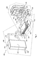
- Apparatus 200 includes a liquid management components generally designated 220, a temperature control system 400 that is associated with a heat sink arrangement 240.
- Fig. 2 depicts the liquid management components 220 in greater detail. Specifically Peltier thermoelectric cooling elements 250 are visible mounted in direct thermal communication with the upper three of six flattened pipes 300 and 302. There are also corresponding elements that are mounted in direct thermal communication with the lower three of said flattened pipes. In the depicted exemplary embodiment, which is configured for cooling, electric leads 252 are connected to a power source (not pictured) so that a cold side of Peltier elements 250 contacts pipes 300 and/or 302. A hot side of Peltier devices 250 faces upwards in the drawing. Depicted exemplary liquid management components also include a reservoir 222, a reservoir inlet 224 and a pump 228. During use pump 228 circulates water through pipes 230 and 232 so that there is an exchange between reservoir 222 and temperature control system 400. Chilled water can be drawn from reservoir 222 via exit port 226.
- Peltier thermoelectric cooling elements 250 ( Fig. 2B ) and the opposite one (not shown) define between them a cooling zone 252 that accommodates the flattened pipes 230 and 232.
- Element 250 and its opposite ones are mounted in direct thermal communication with flattened pipes 300 and 302 and serve to cool fluid flowing through the pipes.
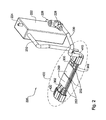
- the thermoelectric cooling element is a in thermal communication with the heat absorption module 610 and its counterpart (not shown) associated with the opposite thermoelectric elements. Module 610 is cooled by a supply of coolant fluid.
- the coolant fluid flows from reservoir 242 via pipe 243 to an inner lumen of module 610 and out through pipes 246 and 345 to a heat dissipation unit (depicted as fan 260) and back to reservoir 242 for recirculation.
- Cooling fluid pump 248 may be installed at any point-in the recirculation path.
- module 610 is cooled by a flow of cooling fluid which is not recycled.
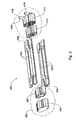
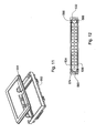
- Fig. 3 is an exploded view of an exemplary conduit system 402 that defines a liquid flow path between inlet port 416 and outlet port 418. It includes a plurality of flattened pipe segments (six in this exemplary embodiment) 300 and 302. In the depicted embodiment, pipes 302 are connected in series so that their inner lumens form a continuous flow path.
- An exemplary connector element 410 includes a fluid inlet port 416 and a fluid outlet port 418.
- Connector element 410 composed of an inner connector element 412 and an outer connector element 414, is one exemplary way to provide flow communication between inner lumens of pipes 300/302. Each of these ports is in flow communication with an inner lumen of one of the pipes.
- Connector element 420 is provided at the other end of the pipe segments, having an inner connector element 422 and an outer connector element 424.
- the flow path through pipes 300/302 is a continuous serpentine path from port 416 to 418 through the six depicted pipes 300 and 302 and caps 410 and 420.
- the flow communication between ports 416 and 418 and one of the pipe segments and between the pipe segments is provided through appropriate channeling arrangements within the connector elements 410 and 420.
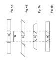
- flattened pipe segments 300,302 have an inner lumen characterized by a Width to Height (W: H) aspect ratio of at least 2:1.
- W: H Width to Height
- increasing W provides more surface to contact Peltier unit 250.
- Fig. 4 depicts pipes 300 and 302 as substantially rectangular in cross section
- Figs. 4A, 4B, 5A and 5B show that a large W:H ration can be achieved using other cross sectional shapes.
- the continuous flow path through lumens of the pipes, provided through the channeling arrangement in the connector elements can be configured differently.
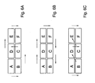
- Figs. 6A, 6B and 6C depict three exemplary flow paths through an arrangement of six pipes shown in schematic cross-section. There three exemplary flow paths are depicted by arrows in a self-explanatory manner.
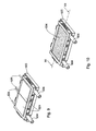
- the liquid cooling system 500 includes a temperature control module 502, with a liquid inlet 504 and a liquid outlet 506, flanked by two heat-absorption modules 510 and 512, all components held together and held together by screws 514.
- a temperature control module 502 with a liquid inlet 504 and a liquid outlet 506, flanked by two heat-absorption modules 510 and 512, all components held together and held together by screws 514.
- disposed between each of modules 510 and 512 and module 502 are two sets of cooling elements 520 and 522, each, in this exemplary embodiment, including two Peltier elements 524, with associated electric leads 526, connected to powering module (not shown).
- sets with two Peltier elements are but an example and the sets of cooling elements may include one or any number of a plurality of Peltier elements. In this particular example all Peltier elements are the same, it being understood that in some other embodiments the Peltier elements may differ from each other in their shape, dimension, as well as in their cooling capacity.
- the two sets of cooling elements define between them a cooling zone 530, accommodating a heat exchange chamber 532.
- the liquid inlet 504 and outlet 506 are in flow communication with the interior of chamber 532.
- the chamber 532 is defined between first and second heat conducting walls 534 and 536 and side walls 538 and 540 that are integral part of the channel-forming block 550, shown in Figs. 13A-13C and that will be described further below.
- Channel-forming block 550 and the two heat-conducting walls 534,536 are held together by two frame elements 552 and 554 that are seen in an exploded view in Fig. 11 and that are snap-assembled by cooperating fastening members designated collectively as 560.
- Channel-forming block 550 has two circumferential grooves 562 and 564, one on each side, which accommodate O-rings 566, 568. As can best be seen in Fig. 12 , a fluid-tight engagement is obtained between the walls 534,536 and the block 550 to thereby defined a confined fluid-tight chamber within the block 550.
- block 550 is patterned on both its inner surfaces 570 and 572. Once fitted between heat conducting walls 534,536 the patterned surfaces define a 3-dimensional, curvilinear flow-path, which will be further detailed below.
- Block 550 has a main divider panel 574, which essentially divides the chamber into two compartments at opposite sides of panel 574 between the panels and heat conducting walls 534,536. Extending from the main divider panel 574 towards the respective walls 534,536 are two arrays of auxiliary panels 576 and 578, thre former extends from side wall 538 toward the opposite side wall leaving a clearance; and the latter extends fully between the side walls.
- auxiliary panels pattern the inner surfaces of block 550 to define U-shaped channel segments 580, each with two ends 582 having each an opening 584 providing flow communication between the ends of U-shaped channel segments in the two faces of the block.
- the 3-dimensional, serpentine flow-path so formed is shown by the arrows in Figs. 13A-13C in a self explanatory manner.
- a flow-path of successive U-shaped channel segments is formed alternating between such segments in the two compartments.
- Inlet 504 and outlet 506 are in flow communication with two respective end channel segments 586 and 588, which are linear (and not U-shaped) leading between the inlet and outlet to openings 584.
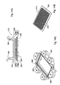
- the module comprises a block 590 that defines a coolant fluid inlet 592 and a coolant fluid outlet 594, which is in flow communication with lumen 596 defined by recess 598 in block 590 and panel 600 of metal block 602.
- Block 590 has a groove 604, tracing the circumference of recess 598, accommodating an O-ring 606 which cooperates with panel 600 to seal lumen 596 in a fluid-tight manner.
- Metal block 602 typically made of copper, includes a plurality of spikes 610 that provide a large heat exchange surface for the coolant liquid flowing through the lumen 596 as represented by the block arrow in Fig. 14A .
- panel 600 When assembled, as can be seen in Fig. 8 , panel 600 bears against the external surface of Peltier elements 520, thereby transporting the generated heat to the spikes, which is then removed by the coolant fluid flowing into a refrigeration unit, for example of the kind shown in Fig. 1 .
Landscapes
- Engineering & Computer Science (AREA)
- Physics & Mathematics (AREA)
- Mechanical Engineering (AREA)
- Thermal Sciences (AREA)
- General Engineering & Computer Science (AREA)
- Chemical & Material Sciences (AREA)
- Combustion & Propulsion (AREA)
- Devices That Are Associated With Refrigeration Equipment (AREA)
- Devices For Dispensing Beverages (AREA)
- Control Of Temperature (AREA)
Claims (15)
- Temperatur-Steuer-/Regelsystem (400, 500) zum Regulieren einer Temperatur einer Flüssigkeit bei ihrem Strömen durch das System, umfassend:einen ersten Satz von einem oder mehreren Temperatur-Steuer-/Regelelementen (250, 520), welche gegenüber einem zweiten Satz von einem oder mehreren Temperatur-Steuer-/Regelelementen (522) angeordnet sind, wobei der erste und der zweite Satz zwischen ihnen eine Temperatur-Steuer-/Regelzone (252, 530) definieren; und gekennzeichnet durchein Leitungssystem (402), welches einen einzelnen Strömungsweg durch die Temperatur-Steuer-/Regelzone von einem Flüssigkeitszufluss (416, 504) zu einem Flüssigkeitsausfluss (418, 506) führend definiert, wobei der Flüssigkeits-Strömungsweg derart eingerichtet ist, dass der Strömungsweg abwechselnd erste (586) und zweite Segmente (588) aufweist, wobei ein oder mehrere erste Segmente in der Nähe von und in wärmeleitender Verbindung mit dem ersten Satz sind, und ein oder mehrere zweite Segmente in der Nähe von und in wärmeleitender Verbindung mit dem zweiten Satz sind.
- System nach Anspruch 1, wobei das Leitungssystem zwei oder mehr den Zufluss und Ausfluss verbindende Strömungswege definiert.
- System nach Anspruch 1 oder 2, wobei der Strömungsweg eine schlangenartige Geometrie aufweist.
- System nach einem der Ansprüche 1 - 3, wobei die Temperatur-Steuer-/Regelelemente thermoelektrische Kühlelemente sind.
- System nach Anspruch 4, wobei die thermoelektrischen Kühlelemente planare Peltier-Elemente mit gegenüberliegenden kalten und heißen Flächen sind, wobei die kalten Flächen der Elemente die Temperatur-Steuer-/Regelzone auskleiden.
- System nach einem der Ansprüche 1 - 5, umfassend eine Wärmetauschkammer (532), welche zwischen einer ersten in wärmeleitender Verbindung mit dem ersten Satz von Temperatur-Steuer-/Regelelementen angeordneten wärmeleitenden Wand (534), einer zweiten in wärmeleitender Verbindung mit dem zweiten Satz von Temperatur-Steuer-/Regelelementen angeordneten wärmeleitenden Wand (536) und Seitenwänden (538, 540) definiert ist; Flüssigkeitseinlass (504) und Flüssigkeitsauslass (506); eine innerhalb der Kammer gebildete Anordnung von Kanälen, welche innerhalb der einen oder mehreren durchgehenden, von dem Einlass zu dem Auslass führenden Strömungswege gebildet ist, wobei eine ersten Gruppe aus einem oder mehreren der Kanäle benachbart zu und in wärmeleitender Verbindung mit der ersten Wand ist und eine zweite Gruppe aus einem oder mehreren der Kanäle benachbart zu und in wärmeleitender Verbindung mit der zweiten Wand ist.
- System nach Anspruch 6, wobei die Kanäle durch innerhalb der Kammern angeordneter Trennplatten gebildet sind.
- System nach Anspruch 6 oder 7, wobei wenigstens einige der Kanäle der ersten Gruppe entlang dem Strömungsweg abwechselnd mit Kanälen der zweiten Gruppe angeordnet sind.
- System nach Anspruch 6, wobei die Wärmetauschkammer eine zwischen den beiden wärmeleitenden Wänden (534, 536) und sich im Wesentlichen parallel dazu erstreckende Haupt-Trennplatte (574) umfasst, um die Kammer in ein erstes Abteil benachbart zu der ersten Wand und ein zweites Abteil benachbart zu der zweiten Wand aufzuteilen; wobei jedes der Abteile durch sich von der Haupt-Trennplatte zu den wärmeleitenden Wänden erstreckende und im Wesentlichen U-förmige Kanalsegmente (580) mit zwei Enden (582) definierende Hilfs-Platten (576, 578) geteilt ist; wobei eine Öffnung (584) in den Haupt-Trennplatten gebildet ist, um Enden der U-förmigen Kanalsegmente in dem ersten Abteil mit Enden eines U-förmigen Kanalsegments in dem zweiten Abteil zu verbinden, um dadurch einen Strömungsweg des U-förmigen Kanalsegments von dem Einlass zu dem Auslass zu bilden.
- System nach einem der Ansprüche 1 - 5, umfassend eine erste Gruppe (300) und eine zweite Gruppe (302) von rohrförmigen Leitungssegmenten, welche aus einem wärmeleitenden Material hergestellt sind, jedes mit einem rechteckigen Querschnitt und sich durch die Temperatur-Steuer-/Regelzone erstreckend, wobei die Segmente der ersten Gruppe proximal zu und in wärmeleitende Verbindung mit Temperatur-Steuer-/Regelelementen des ersten Satzes sind und der zweiten Gruppe proximal zu und in wärmeleitende Verbindung mit Temperatur-Steuer-/Regelelementen des zweiten Satzes sind.
- System nach Anspruch 10, wobei Enden der rohrförmigen Segmente in Verbindungselemente (410, 420) eingepasst sind, welche zwischen sich Strömungswege definieren, welche die Segmente verbinden.
- System nach einem der Ansprüche 6 - 11, wobei die Temperatur-Steuer-/Regelelemente aus thermoelektrischen Elementen und Peltier-Elementen ausgewählt sind.
- System nach Anspruch 12, wobei den thermoelektrischen Elementen eine Wärmesenken-Anordnung (240) zum Transport und zur Abstrahlung von durch die Elemente erzeugter Wärme zugeordnet ist.
- System nach Anspruch 13, wobei die Wärmesenken-Anordnung ein abgeschlossenes Wärmetransport-Leitungssystem umfasst, welches eine zwischen ein Wärmeabsorptionsmodul (610) eingepasste Kühlflüssigkeit enthält, welche in einer Wärmeübertragungs-Verbindung mit dem einen oder den mehreren thermoelektrischen Elementen und einem Wärmeabstrahlungs-Modul (260) ist.
- Vorrichtung zum Abgeben einer temperaturgesteuerten/-geregelten Flüssigkeit, umfassend ein Getränke-Kühlsystem nach einem der Ansprüche 1 - 14.
Applications Claiming Priority (2)
| Application Number | Priority Date | Filing Date | Title |
|---|---|---|---|
| US24071009P | 2009-09-09 | 2009-09-09 | |
| PCT/IL2010/000740 WO2011030339A2 (en) | 2009-09-09 | 2010-09-07 | Temperature control system for a liquid |
Publications (2)
| Publication Number | Publication Date |
|---|---|
| EP2467660A2 EP2467660A2 (de) | 2012-06-27 |
| EP2467660B1 true EP2467660B1 (de) | 2015-06-17 |
Family
ID=43732889
Family Applications (1)
| Application Number | Title | Priority Date | Filing Date |
|---|---|---|---|
| EP10768815.2A Active EP2467660B1 (de) | 2009-09-09 | 2010-09-07 | Temperatursteuerungssystem für eine flüssigkeit |
Country Status (12)
| Country | Link |
|---|---|
| US (1) | US8955336B2 (de) |
| EP (1) | EP2467660B1 (de) |
| JP (1) | JP2013504731A (de) |
| KR (1) | KR20120099638A (de) |
| CN (1) | CN102395850B (de) |
| AU (1) | AU2010293841B2 (de) |
| BR (1) | BR112012005293A2 (de) |
| CA (1) | CA2771874A1 (de) |
| MX (1) | MX2012002338A (de) |
| RU (1) | RU2527505C2 (de) |
| WO (1) | WO2011030339A2 (de) |
| ZA (1) | ZA201201319B (de) |
Families Citing this family (19)
| Publication number | Priority date | Publication date | Assignee | Title |
|---|---|---|---|---|
| IL217851A (en) | 2011-02-08 | 2013-03-24 | Strauss Water Ltd | Beverage dispenser with a removable filter and a removable source beverage tank |
| MX2013006864A (es) | 2011-02-28 | 2013-07-29 | Sistema dispensador de bebidas. | |
| TWI447337B (zh) * | 2011-08-23 | 2014-08-01 | Ind Tech Res Inst | 飲水機 |
| TWI502158B (zh) | 2012-05-28 | 2015-10-01 | Ind Tech Res Inst | 飲水機及其所使用之熱電熱泵裝置 |
| DE102012211259A1 (de) * | 2012-06-29 | 2014-01-02 | Behr Gmbh & Co. Kg | Thermoelektrische Temperiereinheit |
| CA2880508C (en) | 2012-09-13 | 2016-12-13 | Strauss Water Ltd. | Beverage dispensing apparatus with a carbonation system |
| CN104245602B (zh) | 2012-09-21 | 2017-10-27 | 捷通国际有限公司 | 用于水处理系统的选择性水温部件 |
| FR3007999B1 (fr) | 2013-07-03 | 2015-07-17 | 10 Vins | Procede et installation pour la preparation a la degustation de boisson, en particulier de vin |
| CA2933264A1 (en) | 2014-02-06 | 2015-08-13 | Strauss Water Ltd. | Carbonation unit |
| DE102014208362A1 (de) * | 2014-05-05 | 2015-11-05 | MAHLE Behr GmbH & Co. KG | Kombinierter Ein- und Auslasssammler für eine thermoelektrische Temperiereinrichtung |
| WO2016012521A1 (en) | 2014-07-23 | 2016-01-28 | Biotech Trentino S.P.A. | Apparatus for the cooling of a drinking liquid, in particular drinking water, with innovative cooling system with peltier effect |
| WO2016179215A1 (en) * | 2015-05-05 | 2016-11-10 | Tokitae Llc | Refrigeration devices including temperature-controlled container systems |
| US9440839B1 (en) | 2016-01-05 | 2016-09-13 | Cleland Sales Corporation | Preferential distribution of cooling capacity |
| US9738505B2 (en) | 2016-01-05 | 2017-08-22 | Cleland Sales Corporation | Preferential distribution of cooling capacity |
| US10946358B2 (en) * | 2018-08-16 | 2021-03-16 | Beijing Aerospace Propulsion Institute | Skid-mounted depressurizing system |
| IT202100015299A1 (it) * | 2021-06-11 | 2022-12-11 | Irca Spa | Dispositivo, in particolare flow through heater, per riscaldare o raffreddare un flusso di liquido, in particolare acqua, per la preparazione di bevande |
| CN115297681A (zh) * | 2022-08-03 | 2022-11-04 | 台达电子企业管理(上海)有限公司 | 车载功率装置与热管理系统 |
| EP4152906A1 (de) * | 2022-08-25 | 2023-03-22 | Ovh | Kühlanordnung und verfahren zum kühlen von mehreren wärmeerzeugenden komponenten |
| CN120333029B (zh) * | 2025-06-19 | 2025-11-04 | 广东栗子科技有限公司 | 一种制冷水设备 |
Family Cites Families (31)
| Publication number | Priority date | Publication date | Assignee | Title |
|---|---|---|---|---|
| US2058098A (en) * | 1934-04-23 | 1936-10-20 | Hamilton Mfg Co | Cooling and dispensing system |
| US2612357A (en) * | 1947-11-10 | 1952-09-30 | Spacarb Inc | Refrigeration and carbonation unit |
| US2771752A (en) * | 1954-10-18 | 1956-11-27 | Schlitz Brewing Co J | Beer cooling apparatus |
| US2871675A (en) * | 1957-01-25 | 1959-02-03 | Richard T Cornelius | Beverage cooler and dispenser |
| US3982406A (en) * | 1975-11-28 | 1976-09-28 | General Motors Corporation | Refrigerator water storage and dispensing system with water filter |
| US4313491A (en) * | 1978-06-30 | 1982-02-02 | Molitor Industries, Inc. | Coiled heat exchanger |
| US4523697A (en) | 1979-07-11 | 1985-06-18 | Cadbury Schweppes Limited | Liquid dispensing package |
| US4617807A (en) * | 1985-07-08 | 1986-10-21 | Booth, Inc. | Involute coil cold plate |
| US5209069A (en) | 1991-05-06 | 1993-05-11 | Grindmaster Corporation | Compact thermoelectrically cooled beverage dispenser |
| US5285718A (en) | 1992-07-16 | 1994-02-15 | Newco Enterprises, Incorporated | Combination beverage brewer with cold water supply |
| US5732563A (en) * | 1993-09-22 | 1998-03-31 | Imi Cornelius Inc. | Electronically controlled beverage dispenser |
| US5634343A (en) | 1994-01-24 | 1997-06-03 | Alko Group, Ltd. | Beverage cooling dispenser |
| US5501077A (en) | 1994-05-27 | 1996-03-26 | Springwell Dispensers, Inc. | Thermoelectric water chiller |
| CN1110395A (zh) * | 1995-01-24 | 1995-10-18 | 华中理工大学 | 热电式饮料速冻机 |
| CN1118059A (zh) * | 1995-06-30 | 1996-03-06 | 华中理工大学 | 热电制冷饮料速冻机 |
| GB9516486D0 (en) | 1995-08-11 | 1995-10-11 | Jones Timothy R T | Cooling apparatus |
| RU2121635C1 (ru) | 1997-09-08 | 1998-11-10 | Купцова Валентина Сергеевна | Установка для получения горячей и охлажденной питьевой воды |
| RU2154782C2 (ru) | 1998-01-22 | 2000-08-20 | Общество с ограниченной ответственностью МАК-БЭТ | Система охлаждения напитков |
| US6237345B1 (en) | 1998-04-17 | 2001-05-29 | Home Pure L.L.C. | Water cooler and dispenser |
| US6286720B1 (en) * | 1999-06-04 | 2001-09-11 | Lancer Partnership, Ltd. | Beverage dispenser with an improved cooling chamber configuration |
| JP2001031198A (ja) | 1999-07-21 | 2001-02-06 | Nas Toa Co Ltd | 飲料注出装置 |
| JP2001348093A (ja) | 2000-06-02 | 2001-12-18 | Nas Toa Co Ltd | 飲料サーバー |
| US6370884B1 (en) * | 2001-03-30 | 2002-04-16 | Maher I. Kelada | Thermoelectric fluid cooling cartridge |
| WO2003035536A2 (en) * | 2001-10-19 | 2003-05-01 | Manitowoc Foodservice Companies, Inc. | Beverage dispenser with integral ice maker |
| US20030188540A1 (en) * | 2002-04-03 | 2003-10-09 | John Van Winkle | Cooling system for a beverage dispenser |
| US20040025516A1 (en) * | 2002-08-09 | 2004-02-12 | John Van Winkle | Double closed loop thermoelectric heat exchanger |
| NZ540478A (en) | 2002-11-29 | 2007-11-30 | Inbev Sa | Alcohol beverage dispensing apparatus with Peltier cooling unit and thermal bridge |
| GB2398064B (en) | 2003-02-05 | 2006-02-22 | Ebac Ltd | Chilled liquid dispensers |
| US7024882B2 (en) * | 2003-09-16 | 2006-04-11 | William Scott Carmichael | Cooler with ordered refilling |
| US20060075761A1 (en) | 2004-10-07 | 2006-04-13 | Kitchens Mark C | Apparatus for cooled or heated on demand drinking water and process for making same |
| US20060096300A1 (en) | 2004-10-27 | 2006-05-11 | Fred Reinstein | Water dispenser having thermoelectric cooling chips |
-
2010
- 2010-09-07 RU RU2012113560/13A patent/RU2527505C2/ru not_active IP Right Cessation
- 2010-09-07 US US13/394,667 patent/US8955336B2/en active Active
- 2010-09-07 CN CN201080001666.9A patent/CN102395850B/zh active Active
- 2010-09-07 WO PCT/IL2010/000740 patent/WO2011030339A2/en not_active Ceased
- 2010-09-07 CA CA2771874A patent/CA2771874A1/en not_active Abandoned
- 2010-09-07 JP JP2012528499A patent/JP2013504731A/ja active Pending
- 2010-09-07 BR BR112012005293A patent/BR112012005293A2/pt not_active IP Right Cessation
- 2010-09-07 AU AU2010293841A patent/AU2010293841B2/en not_active Ceased
- 2010-09-07 KR KR1020127008126A patent/KR20120099638A/ko not_active Withdrawn
- 2010-09-07 EP EP10768815.2A patent/EP2467660B1/de active Active
- 2010-09-07 MX MX2012002338A patent/MX2012002338A/es not_active Application Discontinuation
-
2012
- 2012-02-22 ZA ZA2012/01319A patent/ZA201201319B/en unknown
Also Published As
| Publication number | Publication date |
|---|---|
| HK1163239A1 (zh) | 2012-09-07 |
| WO2011030339A2 (en) | 2011-03-17 |
| WO2011030339A3 (en) | 2011-10-13 |
| BR112012005293A2 (pt) | 2016-03-22 |
| ZA201201319B (en) | 2014-07-30 |
| CN102395850B (zh) | 2016-01-20 |
| AU2010293841A1 (en) | 2012-03-15 |
| KR20120099638A (ko) | 2012-09-11 |
| CA2771874A1 (en) | 2011-03-17 |
| US8955336B2 (en) | 2015-02-17 |
| AU2010293841B2 (en) | 2013-11-28 |
| MX2012002338A (es) | 2012-07-10 |
| RU2012113560A (ru) | 2013-10-20 |
| JP2013504731A (ja) | 2013-02-07 |
| EP2467660A2 (de) | 2012-06-27 |
| RU2527505C2 (ru) | 2014-09-10 |
| US20120167597A1 (en) | 2012-07-05 |
| CN102395850A (zh) | 2012-03-28 |
Similar Documents
| Publication | Publication Date | Title |
|---|---|---|
| EP2467660B1 (de) | Temperatursteuerungssystem für eine flüssigkeit | |
| US20080010999A1 (en) | Device for cooling food | |
| EP2791598A1 (de) | Bedarfsabhängiger getränkekühler | |
| KR101435107B1 (ko) | 열전소자를 이용한 블록 형태로 탈부착이 가능한 열전소자를 이용한 교체형 정수기 | |
| US10107548B2 (en) | Heat transfer device | |
| US20060075761A1 (en) | Apparatus for cooled or heated on demand drinking water and process for making same | |
| CN209801916U (zh) | 水冷循环饮用液体半导体制冷系统及制冷设备 | |
| KR101823554B1 (ko) | 정수기 냉각장치 | |
| IL218274A (en) | Liquid Tertile Control System | |
| US12055348B2 (en) | Heat exchange apparatus and method of manufacturing the same | |
| KR20190093936A (ko) | 냉수 공급 시스템, 이를 포함하는 음용수 공급장치 및 제어 방법 | |
| KR20180080022A (ko) | 냉온 매트장치 | |
| HK1163239B (en) | Temperature control system for a liquid | |
| CN112629149B (zh) | 一种用于制冷或加热液体的设备 | |
| JP2009002543A (ja) | 冷水供給装置 | |
| JP6643302B2 (ja) | 飲料ディスペンサー | |
| KR20080097038A (ko) | 정수기용 순간 냉각 장치 | |
| KR20180080019A (ko) | 냉온 매트장치 | |
| JP2009174753A (ja) | 熱交換器及びヒートポンプ給湯機 | |
| JP2006057891A (ja) | 冷却液体製造装置 | |
| CN209944833U (zh) | 家用可拆分式冰箱组件及冰箱 | |
| JPH0734307Y2 (ja) | ペルチェ効果を利用した冷水器における水路構造 | |
| KR20250132042A (ko) | 냉수 생성 장치 | |
| KR102562278B1 (ko) | 냉수 공급 시스템, 이를 포함하는 음용수 공급장치 및 제어 방법 | |
| KR20180080017A (ko) | 냉온 매트장치 |
Legal Events
| Date | Code | Title | Description |
|---|---|---|---|
| PUAI | Public reference made under article 153(3) epc to a published international application that has entered the european phase |
Free format text: ORIGINAL CODE: 0009012 |
|
| 17P | Request for examination filed |
Effective date: 20120322 |
|
| AK | Designated contracting states |
Kind code of ref document: A2 Designated state(s): AL AT BE BG CH CY CZ DE DK EE ES FI FR GB GR HR HU IE IS IT LI LT LU LV MC MK MT NL NO PL PT RO SE SI SK SM TR |
|
| AX | Request for extension of the european patent |
Extension state: BA ME RS |
|
| 17Q | First examination report despatched |
Effective date: 20140701 |
|
| REG | Reference to a national code |
Ref country code: DE Ref legal event code: R079 Ref document number: 602010025322 Country of ref document: DE Free format text: PREVIOUS MAIN CLASS: F25D0031000000 Ipc: F25B0021020000 |
|
| RIC1 | Information provided on ipc code assigned before grant |
Ipc: F25B 21/02 20060101AFI20150212BHEP Ipc: F25B 21/04 20060101ALI20150212BHEP Ipc: F25D 31/00 20060101ALI20150212BHEP |
|
| GRAP | Despatch of communication of intention to grant a patent |
Free format text: ORIGINAL CODE: EPIDOSNIGR1 |
|
| INTG | Intention to grant announced |
Effective date: 20150324 |
|
| GRAS | Grant fee paid |
Free format text: ORIGINAL CODE: EPIDOSNIGR3 |
|
| GRAA | (expected) grant |
Free format text: ORIGINAL CODE: 0009210 |
|
| AK | Designated contracting states |
Kind code of ref document: B1 Designated state(s): AL AT BE BG CH CY CZ DE DK EE ES FI FR GB GR HR HU IE IS IT LI LT LU LV MC MK MT NL NO PL PT RO SE SI SK SM TR |
|
| AX | Request for extension of the european patent |
Extension state: BA ME RS |
|
| REG | Reference to a national code |
Ref country code: GB Ref legal event code: FG4D |
|
| REG | Reference to a national code |
Ref country code: CH Ref legal event code: EP |
|
| REG | Reference to a national code |
Ref country code: AT Ref legal event code: REF Ref document number: 732172 Country of ref document: AT Kind code of ref document: T Effective date: 20150715 |
|
| REG | Reference to a national code |
Ref country code: IE Ref legal event code: FG4D |
|
| REG | Reference to a national code |
Ref country code: DE Ref legal event code: R096 Ref document number: 602010025322 Country of ref document: DE |
|
| REG | Reference to a national code |
Ref country code: FR Ref legal event code: PLFP Year of fee payment: 6 |
|
| PG25 | Lapsed in a contracting state [announced via postgrant information from national office to epo] |
Ref country code: HR Free format text: LAPSE BECAUSE OF FAILURE TO SUBMIT A TRANSLATION OF THE DESCRIPTION OR TO PAY THE FEE WITHIN THE PRESCRIBED TIME-LIMIT Effective date: 20150617 Ref country code: LT Free format text: LAPSE BECAUSE OF FAILURE TO SUBMIT A TRANSLATION OF THE DESCRIPTION OR TO PAY THE FEE WITHIN THE PRESCRIBED TIME-LIMIT Effective date: 20150617 Ref country code: NO Free format text: LAPSE BECAUSE OF FAILURE TO SUBMIT A TRANSLATION OF THE DESCRIPTION OR TO PAY THE FEE WITHIN THE PRESCRIBED TIME-LIMIT Effective date: 20150917 Ref country code: FI Free format text: LAPSE BECAUSE OF FAILURE TO SUBMIT A TRANSLATION OF THE DESCRIPTION OR TO PAY THE FEE WITHIN THE PRESCRIBED TIME-LIMIT Effective date: 20150617 |
|
| PGFP | Annual fee paid to national office [announced via postgrant information from national office to epo] |
Ref country code: GB Payment date: 20150930 Year of fee payment: 6 |
|
| REG | Reference to a national code |
Ref country code: AT Ref legal event code: MK05 Ref document number: 732172 Country of ref document: AT Kind code of ref document: T Effective date: 20150617 |
|
| REG | Reference to a national code |
Ref country code: LT Ref legal event code: MG4D Ref country code: NL Ref legal event code: MP Effective date: 20150617 |
|
| PG25 | Lapsed in a contracting state [announced via postgrant information from national office to epo] |
Ref country code: BG Free format text: LAPSE BECAUSE OF FAILURE TO SUBMIT A TRANSLATION OF THE DESCRIPTION OR TO PAY THE FEE WITHIN THE PRESCRIBED TIME-LIMIT Effective date: 20150917 Ref country code: GR Free format text: LAPSE BECAUSE OF FAILURE TO SUBMIT A TRANSLATION OF THE DESCRIPTION OR TO PAY THE FEE WITHIN THE PRESCRIBED TIME-LIMIT Effective date: 20150918 Ref country code: LV Free format text: LAPSE BECAUSE OF FAILURE TO SUBMIT A TRANSLATION OF THE DESCRIPTION OR TO PAY THE FEE WITHIN THE PRESCRIBED TIME-LIMIT Effective date: 20150617 |
|
| PGFP | Annual fee paid to national office [announced via postgrant information from national office to epo] |
Ref country code: FR Payment date: 20150928 Year of fee payment: 6 |
|
| PG25 | Lapsed in a contracting state [announced via postgrant information from national office to epo] |
Ref country code: EE Free format text: LAPSE BECAUSE OF FAILURE TO SUBMIT A TRANSLATION OF THE DESCRIPTION OR TO PAY THE FEE WITHIN THE PRESCRIBED TIME-LIMIT Effective date: 20150617 |
|
| PG25 | Lapsed in a contracting state [announced via postgrant information from national office to epo] |
Ref country code: PT Free format text: LAPSE BECAUSE OF FAILURE TO SUBMIT A TRANSLATION OF THE DESCRIPTION OR TO PAY THE FEE WITHIN THE PRESCRIBED TIME-LIMIT Effective date: 20151019 Ref country code: CZ Free format text: LAPSE BECAUSE OF FAILURE TO SUBMIT A TRANSLATION OF THE DESCRIPTION OR TO PAY THE FEE WITHIN THE PRESCRIBED TIME-LIMIT Effective date: 20150617 Ref country code: ES Free format text: LAPSE BECAUSE OF FAILURE TO SUBMIT A TRANSLATION OF THE DESCRIPTION OR TO PAY THE FEE WITHIN THE PRESCRIBED TIME-LIMIT Effective date: 20150617 Ref country code: IS Free format text: LAPSE BECAUSE OF FAILURE TO SUBMIT A TRANSLATION OF THE DESCRIPTION OR TO PAY THE FEE WITHIN THE PRESCRIBED TIME-LIMIT Effective date: 20151017 Ref country code: AT Free format text: LAPSE BECAUSE OF FAILURE TO SUBMIT A TRANSLATION OF THE DESCRIPTION OR TO PAY THE FEE WITHIN THE PRESCRIBED TIME-LIMIT Effective date: 20150617 Ref country code: PL Free format text: LAPSE BECAUSE OF FAILURE TO SUBMIT A TRANSLATION OF THE DESCRIPTION OR TO PAY THE FEE WITHIN THE PRESCRIBED TIME-LIMIT Effective date: 20150617 Ref country code: RO Free format text: LAPSE BECAUSE OF NON-PAYMENT OF DUE FEES Effective date: 20150617 Ref country code: SK Free format text: LAPSE BECAUSE OF FAILURE TO SUBMIT A TRANSLATION OF THE DESCRIPTION OR TO PAY THE FEE WITHIN THE PRESCRIBED TIME-LIMIT Effective date: 20150617 |
|
| REG | Reference to a national code |
Ref country code: DE Ref legal event code: R097 Ref document number: 602010025322 Country of ref document: DE |
|
| PLBE | No opposition filed within time limit |
Free format text: ORIGINAL CODE: 0009261 |
|
| STAA | Information on the status of an ep patent application or granted ep patent |
Free format text: STATUS: NO OPPOSITION FILED WITHIN TIME LIMIT |
|
| PG25 | Lapsed in a contracting state [announced via postgrant information from national office to epo] |
Ref country code: MC Free format text: LAPSE BECAUSE OF FAILURE TO SUBMIT A TRANSLATION OF THE DESCRIPTION OR TO PAY THE FEE WITHIN THE PRESCRIBED TIME-LIMIT Effective date: 20150617 Ref country code: DK Free format text: LAPSE BECAUSE OF FAILURE TO SUBMIT A TRANSLATION OF THE DESCRIPTION OR TO PAY THE FEE WITHIN THE PRESCRIBED TIME-LIMIT Effective date: 20150617 Ref country code: IT Free format text: LAPSE BECAUSE OF FAILURE TO SUBMIT A TRANSLATION OF THE DESCRIPTION OR TO PAY THE FEE WITHIN THE PRESCRIBED TIME-LIMIT Effective date: 20150617 Ref country code: LU Free format text: LAPSE BECAUSE OF FAILURE TO SUBMIT A TRANSLATION OF THE DESCRIPTION OR TO PAY THE FEE WITHIN THE PRESCRIBED TIME-LIMIT Effective date: 20150907 |
|
| REG | Reference to a national code |
Ref country code: CH Ref legal event code: PL |
|
| 26N | No opposition filed |
Effective date: 20160318 |
|
| REG | Reference to a national code |
Ref country code: IE Ref legal event code: MM4A |
|
| PG25 | Lapsed in a contracting state [announced via postgrant information from national office to epo] |
Ref country code: LI Free format text: LAPSE BECAUSE OF NON-PAYMENT OF DUE FEES Effective date: 20150930 Ref country code: CH Free format text: LAPSE BECAUSE OF NON-PAYMENT OF DUE FEES Effective date: 20150930 Ref country code: IE Free format text: LAPSE BECAUSE OF NON-PAYMENT OF DUE FEES Effective date: 20150907 |
|
| PG25 | Lapsed in a contracting state [announced via postgrant information from national office to epo] |
Ref country code: SI Free format text: LAPSE BECAUSE OF FAILURE TO SUBMIT A TRANSLATION OF THE DESCRIPTION OR TO PAY THE FEE WITHIN THE PRESCRIBED TIME-LIMIT Effective date: 20150617 |
|
| PG25 | Lapsed in a contracting state [announced via postgrant information from national office to epo] |
Ref country code: BE Free format text: LAPSE BECAUSE OF FAILURE TO SUBMIT A TRANSLATION OF THE DESCRIPTION OR TO PAY THE FEE WITHIN THE PRESCRIBED TIME-LIMIT Effective date: 20150617 |
|
| PG25 | Lapsed in a contracting state [announced via postgrant information from national office to epo] |
Ref country code: MT Free format text: LAPSE BECAUSE OF FAILURE TO SUBMIT A TRANSLATION OF THE DESCRIPTION OR TO PAY THE FEE WITHIN THE PRESCRIBED TIME-LIMIT Effective date: 20150617 |
|
| GBPC | Gb: european patent ceased through non-payment of renewal fee |
Effective date: 20160907 |
|
| PG25 | Lapsed in a contracting state [announced via postgrant information from national office to epo] |
Ref country code: HU Free format text: LAPSE BECAUSE OF FAILURE TO SUBMIT A TRANSLATION OF THE DESCRIPTION OR TO PAY THE FEE WITHIN THE PRESCRIBED TIME-LIMIT; INVALID AB INITIO Effective date: 20100907 Ref country code: SM Free format text: LAPSE BECAUSE OF FAILURE TO SUBMIT A TRANSLATION OF THE DESCRIPTION OR TO PAY THE FEE WITHIN THE PRESCRIBED TIME-LIMIT Effective date: 20150617 |
|
| PG25 | Lapsed in a contracting state [announced via postgrant information from national office to epo] |
Ref country code: NL Free format text: LAPSE BECAUSE OF FAILURE TO SUBMIT A TRANSLATION OF THE DESCRIPTION OR TO PAY THE FEE WITHIN THE PRESCRIBED TIME-LIMIT Effective date: 20150617 Ref country code: SE Free format text: LAPSE BECAUSE OF FAILURE TO SUBMIT A TRANSLATION OF THE DESCRIPTION OR TO PAY THE FEE WITHIN THE PRESCRIBED TIME-LIMIT Effective date: 20150617 Ref country code: CY Free format text: LAPSE BECAUSE OF FAILURE TO SUBMIT A TRANSLATION OF THE DESCRIPTION OR TO PAY THE FEE WITHIN THE PRESCRIBED TIME-LIMIT Effective date: 20150617 |
|
| REG | Reference to a national code |
Ref country code: FR Ref legal event code: ST Effective date: 20170531 |
|
| PG25 | Lapsed in a contracting state [announced via postgrant information from national office to epo] |
Ref country code: FR Free format text: LAPSE BECAUSE OF NON-PAYMENT OF DUE FEES Effective date: 20160930 Ref country code: GB Free format text: LAPSE BECAUSE OF NON-PAYMENT OF DUE FEES Effective date: 20160907 |
|
| PG25 | Lapsed in a contracting state [announced via postgrant information from national office to epo] |
Ref country code: TR Free format text: LAPSE BECAUSE OF FAILURE TO SUBMIT A TRANSLATION OF THE DESCRIPTION OR TO PAY THE FEE WITHIN THE PRESCRIBED TIME-LIMIT Effective date: 20150617 |
|
| PG25 | Lapsed in a contracting state [announced via postgrant information from national office to epo] |
Ref country code: MK Free format text: LAPSE BECAUSE OF FAILURE TO SUBMIT A TRANSLATION OF THE DESCRIPTION OR TO PAY THE FEE WITHIN THE PRESCRIBED TIME-LIMIT Effective date: 20150617 |
|
| PG25 | Lapsed in a contracting state [announced via postgrant information from national office to epo] |
Ref country code: AL Free format text: LAPSE BECAUSE OF FAILURE TO SUBMIT A TRANSLATION OF THE DESCRIPTION OR TO PAY THE FEE WITHIN THE PRESCRIBED TIME-LIMIT Effective date: 20150617 |
|
| PGFP | Annual fee paid to national office [announced via postgrant information from national office to epo] |
Ref country code: DE Payment date: 20191129 Year of fee payment: 10 |
|
| REG | Reference to a national code |
Ref country code: DE Ref legal event code: R119 Ref document number: 602010025322 Country of ref document: DE |
|
| PG25 | Lapsed in a contracting state [announced via postgrant information from national office to epo] |
Ref country code: DE Free format text: LAPSE BECAUSE OF NON-PAYMENT OF DUE FEES Effective date: 20210401 |