EP2467592B1 - High pressure fuel pump - Google Patents
High pressure fuel pump Download PDFInfo
- Publication number
- EP2467592B1 EP2467592B1 EP10728193.3A EP10728193A EP2467592B1 EP 2467592 B1 EP2467592 B1 EP 2467592B1 EP 10728193 A EP10728193 A EP 10728193A EP 2467592 B1 EP2467592 B1 EP 2467592B1
- Authority
- EP
- European Patent Office
- Prior art keywords
- pump housing
- housing
- housing part
- pump
- pressure fuel
- Prior art date
- Legal status (The legal status is an assumption and is not a legal conclusion. Google has not performed a legal analysis and makes no representation as to the accuracy of the status listed.)
- Active
Links
- 239000000446 fuel Substances 0.000 title claims description 14
- 238000007789 sealing Methods 0.000 claims description 12
- 239000000463 material Substances 0.000 claims description 5
- 238000002485 combustion reaction Methods 0.000 claims description 4
- 230000005489 elastic deformation Effects 0.000 claims description 4
- 230000000694 effects Effects 0.000 claims description 2
- 230000004308 accommodation Effects 0.000 claims 1
- 238000003825 pressing Methods 0.000 description 9
- 230000015572 biosynthetic process Effects 0.000 description 4
- 238000004519 manufacturing process Methods 0.000 description 3
- 238000003860 storage Methods 0.000 description 3
- 230000000712 assembly Effects 0.000 description 2
- 238000000429 assembly Methods 0.000 description 2
- 239000000314 lubricant Substances 0.000 description 2
- 238000004891 communication Methods 0.000 description 1
- 230000008878 coupling Effects 0.000 description 1
- 238000010168 coupling process Methods 0.000 description 1
- 238000005859 coupling reaction Methods 0.000 description 1
- 238000011161 development Methods 0.000 description 1
- 230000018109 developmental process Effects 0.000 description 1
- 239000002283 diesel fuel Substances 0.000 description 1
- 239000002360 explosive Substances 0.000 description 1
- 238000000034 method Methods 0.000 description 1
Images
Classifications
-
- F—MECHANICAL ENGINEERING; LIGHTING; HEATING; WEAPONS; BLASTING
- F02—COMBUSTION ENGINES; HOT-GAS OR COMBUSTION-PRODUCT ENGINE PLANTS
- F02M—SUPPLYING COMBUSTION ENGINES IN GENERAL WITH COMBUSTIBLE MIXTURES OR CONSTITUENTS THEREOF
- F02M59/00—Pumps specially adapted for fuel-injection and not provided for in groups F02M39/00 -F02M57/00, e.g. rotary cylinder-block type of pumps
- F02M59/44—Details, components parts, or accessories not provided for in, or of interest apart from, the apparatus of groups F02M59/02 - F02M59/42; Pumps having transducers, e.g. to measure displacement of pump rack or piston
- F02M59/48—Assembling; Disassembling; Replacing
-
- F—MECHANICAL ENGINEERING; LIGHTING; HEATING; WEAPONS; BLASTING
- F04—POSITIVE - DISPLACEMENT MACHINES FOR LIQUIDS; PUMPS FOR LIQUIDS OR ELASTIC FLUIDS
- F04B—POSITIVE-DISPLACEMENT MACHINES FOR LIQUIDS; PUMPS
- F04B1/00—Multi-cylinder machines or pumps characterised by number or arrangement of cylinders
- F04B1/04—Multi-cylinder machines or pumps characterised by number or arrangement of cylinders having cylinders in star- or fan-arrangement
- F04B1/0404—Details or component parts
-
- F—MECHANICAL ENGINEERING; LIGHTING; HEATING; WEAPONS; BLASTING
- F04—POSITIVE - DISPLACEMENT MACHINES FOR LIQUIDS; PUMPS FOR LIQUIDS OR ELASTIC FLUIDS
- F04B—POSITIVE-DISPLACEMENT MACHINES FOR LIQUIDS; PUMPS
- F04B53/00—Component parts, details or accessories not provided for in, or of interest apart from, groups F04B1/00 - F04B23/00 or F04B39/00 - F04B47/00
- F04B53/16—Casings; Cylinders; Cylinder liners or heads; Fluid connections
-
- F—MECHANICAL ENGINEERING; LIGHTING; HEATING; WEAPONS; BLASTING
- F04—POSITIVE - DISPLACEMENT MACHINES FOR LIQUIDS; PUMPS FOR LIQUIDS OR ELASTIC FLUIDS
- F04B—POSITIVE-DISPLACEMENT MACHINES FOR LIQUIDS; PUMPS
- F04B9/00—Piston machines or pumps characterised by the driving or driven means to or from their working members
- F04B9/02—Piston machines or pumps characterised by the driving or driven means to or from their working members the means being mechanical
- F04B9/04—Piston machines or pumps characterised by the driving or driven means to or from their working members the means being mechanical the means being cams, eccentrics or pin-and-slot mechanisms
- F04B9/042—Piston machines or pumps characterised by the driving or driven means to or from their working members the means being mechanical the means being cams, eccentrics or pin-and-slot mechanisms the means being cams
-
- F—MECHANICAL ENGINEERING; LIGHTING; HEATING; WEAPONS; BLASTING
- F16—ENGINEERING ELEMENTS AND UNITS; GENERAL MEASURES FOR PRODUCING AND MAINTAINING EFFECTIVE FUNCTIONING OF MACHINES OR INSTALLATIONS; THERMAL INSULATION IN GENERAL
- F16C—SHAFTS; FLEXIBLE SHAFTS; ELEMENTS OR CRANKSHAFT MECHANISMS; ROTARY BODIES OTHER THAN GEARING ELEMENTS; BEARINGS
- F16C35/00—Rigid support of bearing units; Housings, e.g. caps, covers
- F16C35/02—Rigid support of bearing units; Housings, e.g. caps, covers in the case of sliding-contact bearings
Definitions
- the invention relates to a high-pressure fuel pump of an internal combustion engine with the features of the preamble of claim 1.
- Such high pressure pumps are well known in the art. They are used in motor vehicles in particular to promote fuel, preferably diesel fuel, in a high-pressure accumulator, from where the fuel is injected under high pressure into the combustion chamber of the internal combustion engine.
- a high-pressure pump has a drive shaft with a cam or eccentric drive, by means of which a pump piston of at least one pump element is driven to a stroke movement. In the suction stroke of the pump piston fuel is sucked from a low pressure region and compressed in the delivery stroke of the pump piston in the pump working chamber, then to be supplied under high pressure standing the high-pressure accumulator.
- the high-pressure pump should be simple and therefore inexpensive to manufacture.
- the proposed high-pressure fuel pump has a pump housing in which is received for actuating at least one pump housing arranged in the pump element, a drive shaft with a cam or Exzentertrieb and is rotatably mounted about a drive shaft longitudinal axis.
- the pump housing comprises a housing part with a bearing bore.
- the housing part is connected to the pump housing via a frictional press connection, wherein the frictional press connection is formed in that the housing part has at least one portion which has a radial excess relative to a recess of the pump housing, in which the housing part is inserted.
- the press connection is preferably designed such that axial forces introduced via the drive shaft can also be accommodated.
- a screw is thus unnecessary, so that the attachment of the housing part can be done without screws on the pump housing.
- the formation of a flange is unnecessary, so the total material and thus Weight can be saved. Furthermore, eliminates the costly production of holes for receiving the mounting screws, so that overall simplifies the production and thus made more cost-effective.
- the housing part to form the frictional press connection a first portion a and a second portion b with radial excess relative to the recess of the pump housing, so that two press dressings are formed for frictional connection of the housing part with the pump housing.
- the first section a and the second section b are arranged spaced from one another in the axial direction relative to the drive shaft longitudinal axis.
- a large axial distance allows alignment of the housing part over a large length in the axial direction and thus ensures the Koaxialtmaschine of the housing part to the pump housing.
- the axial distance is therefore preferably chosen as large as possible.
- the frictional connection of the housing part with the pump housing via two axially spaced-apart press dressings also has the advantage that between the two sections a and b can be formed with radial excess a usable as a return groove annulus.
- a return bore for returning the bearing lubricant quantity into the system return flows into this annular space.
- the return bore may be formed as a radial bore or obliquely extending in a wall region of the housing part.
- An annular space as a return groove, that is a circumferential return groove has the advantage that even with a different angular position of the return bores in the housing part and in the pump housing the connection to the system return is guaranteed.
- the circumferential return groove is sealed by the further inside pressing connection of the section a with respect to the pump interior. This can be dispensed with the arrangement of a sealing ring. If leaks nevertheless occur, no serious effects are to be expected since the leakage takes place inside the pump.
- the radial excess of the first portion a of the housing part with respect to the recess of the pump housing differs from that radial excess of the second section b.
- the radial excess of the second portion b is greater than that of the first section a selected.
- the press connection in the region of the second section b also has a sealing function.
- the press connection can therefore replace a sealing ring for sealing the annular space from the outside.
- the radial oversize and the axial extension of the section a and / or the section b for producing a press connection are selected such that the minimum pressing force is> 5 kN and a common axial compressive force of about 1 kN can be accommodated.
- an annular groove is therefore preferably provided in the pump housing in the region of at least one press connection, which causes an elastic deformation of the pump housing and thus a decoupling in the region of the press connection.
- the annular groove provided for decoupling the pump housing is preferably arranged coaxially to the recess of the pump housing, in which the housing part is inserted.
- the annular groove extends from an end face of the pump housing substantially axially and is advantageously equipped with a notch-sensitive radius.
- a corresponding annular groove may also be formed in an end face of the housing part in order to counteract undesired deformations. If the arrangement of a plain bearing bush in the bearing bore of the housing part is provided, this may be cylindrical or formed as a collar bushing.
- annular groove is used for decoupling the pump housing, its axial extent is preferably chosen to be greater than the axial extent of the respective pressing area, the relief of which is provided by the annular groove. That is, the axial extent of the annular groove is preferably selected to be larger than the axial extent of the sections a or b with radial oversize. As a result, an uneven surface pressure in the longitudinal direction can be avoided. Wieterhin preferably the axial extent of the annular groove is at least 20% greater than the axial extent of the respective pressing range selected.
- an interlocking connection of the housing part to the pump housing is additionally provided for axially securing the housing part within the recess of the pump housing.
- the positive connection can be effected for example by at least one screw or at least one pin.
- the at least one screw or the at least one pin is guided perpendicular to the drive shaft longitudinal axis.
- an explosive or retaining ring can be used to produce a positive connection. Due to the additional positive connection, the high-pressure pump is also suitable for applications with particularly high requirements.
- the housing part and the pump housing made of the same material, so that the housing part and the pump housing have the same values in terms of Young's modulus and thermal expansion coefficient.
- An operational release of at least one press connection can thus be largely excluded.
- An additional positive connection is therefore usually unnecessary.
- any sealing function is permanently ensured in a pressing area. If different materials are used to produce the housing part and the pump housing, it must be ensured, especially if the housing part is fastened to the pump housing via at least one press connection, that the minimum pressing force is sufficient to ensure the holding function over the entire operating temperature range.
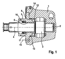
- the in the Fig. 1 illustrated and known from the prior art high-pressure pump comprises a pump housing 1, in which for receiving and rotatable mounting of a drive shaft 2 about a drive shaft longitudinal axis 4, a flange-shaped housing part 5 is added. To form a sliding bearing a plain bearing bush 11 is inserted in a bearing bore 6 of the housing part 5. The drive shaft 2 is guided through the plain bearing bushing 11 and held at the end in a further bearing arrangement designed as a slide bearing in the pump housing 1. Between the two slide bearings, the drive shaft 2 has a cam drive 3 for actuating a pump piston (not shown) of at least one pump element (also not shown) for conveying fuel.
- the housing part 5 is struck axially on the pump housing 1 via its flange 14.
- the flange 14 is screwed by at least one screw 15 with the pump housing.
- 4 or 6 screws 15 are arranged at the same angular distance from one another in the flange 14 for fastening the housing part 5.
- the screws 15 cause a positive connection through which axial forces introduced via the drive shaft 2 can be accommodated.
- Via a cylindrical projection on the flange 14, the housing part 5 is also supported in the radial direction in a recess 8 of the pump housing 1.
- At least one sealing ring 13 is arranged to prevent the escape of a certain Lagerschmiermenge.
- a corresponding function has a shaft seal 16, which seals the bearing gap between the drive shaft 2 and the housing part 5 to the outside.
- annular groove 12 is formed in an end face of the housing part 5, which ensures a certain elastic deformability of the housing part 5 in the edge region of the bearing.
- the elastic deformability brought about by the annular groove 12 is particularly advantageous when high transverse forces from the cam drive 3 act on the drive shaft 2 and thus lead to a tilting of the drive shaft 2 with respect to the drive shaft longitudinal axis 4. In such a case, the edge regions of the bearing experience a high load, which, however, can be reduced by a corresponding elastic deformation.
- a erfidnungsdorfe high-pressure pump differs from the high-pressure pump described above in that the housing part 5 is frictionally connected to the pump housing 1 via a press connection 7, wherein the frictional press connection is produced in that the housing part 5 in at least one section a, b, a radial excess relative to the recess 8 of the pump housing 1 has, in which the housing part 5 is received.
- a screwing of the housing part 5 with the pump housing 1 is thus unnecessary, so that the formation of a flange 14 is not required. This saves material and weight.
- the housing part 5 of the embodiments of Figures 2 and 3 is therefore substantially hollow cylindrical.
- a press connection 7 is considered to be sufficient over only a radially oversized portion a for fixing the housing part 5 on the pump housing 1, the embodiment with two press dressings for the reasons mentioned below is preferred.
- the housing part 5 has two sections a and b, which have a radial excess with respect to the recess 8 of the pump housing 1.
- a press connection 7 is produced in sections a and b.
- the sections a and b are axially spaced from one another on the housing part 5, so that an annular space 9 is formed between the sections a and b.
- the annular space 9 is used as a return groove to supply via a return bore 10 a certain amount of bearing lubricant back to a system return (not shown).
- the return bore 10 is designed as a radial bore.
- section b Opposite the pump interior of the annular space 9 is sealed by the press connection 7 of the section a, the radial excess is dimensioned such that the press connection 7 at the same time exerts a sealing function.
- section b has no axial excess sufficient for the exercise of a sealing function, so that the annular space 9 is sealed to the outside via a sealing ring 13.
- Such a sealing ring 13 is dispensable, although the radial excess of the portion b relative to the recess 8 of the pump housing 1 is raised to a corresponding level.
- the sealing of the drive shaft 2 relative to the housing part 5 takes over a shaft seal 16th
- FIG. 2 In the embodiment of the FIG. 2 is in the bearing bore 6 of the housing part 5 a collar bushing used as a plain bearing bush 11.
- the housing part 5 in this area has an annular groove 12 introduced on the front side, on account of which the edge region of the housing part 5 can deform elastically. Deformation of the plain bearing bush is prevented, so that the bearing capacity of the bearing is still ensured.
- annular groove 12 may also be formed on an end face of the pump housing 1.
- the annular groove 12 compensates in the present example, the interference pressure of the press connection 7 of the section b, by allowing an elastic deformation of the pump housing 1.
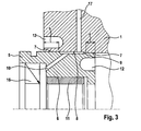
- FIG. 3 continues to differ from that of the FIG. 2 by the plain bearing bush 11 is cylindrical and not designed as a collar bushing.
- a collar portion 18 may be formed on the housing part 5.
- the return bore 10 is not designed as a radial bore, but running obliquely. About the annulus 10, the return bore 10 is in communication with a housing bore 17, which in turn is connected to the system return.
Landscapes
- Engineering & Computer Science (AREA)
- General Engineering & Computer Science (AREA)
- Mechanical Engineering (AREA)
- Chemical & Material Sciences (AREA)
- Combustion & Propulsion (AREA)
- Details And Applications Of Rotary Liquid Pumps (AREA)
- Fuel-Injection Apparatus (AREA)
- Details Of Reciprocating Pumps (AREA)
Description
Die Erfindung betrifft eine Kraftstoffhochdruckpumpe einer Brennkraftmaschine mit den Merkmalen des Oberbegriffes des Anspruchs 1.The invention relates to a high-pressure fuel pump of an internal combustion engine with the features of the preamble of claim 1.
Derartige Hochdruckpumpen sind aus dem Stand der Technik hinlänglich bekannt. Sie werden in Kraftfahrzeugen insbesondere dazu eingesetzt, Kraftstoff, vorzugsweise Dieselkraftstoff, in einen Hochdruckspeicher zu fördern, von wo aus der Kraftstoff unter hohem Druck in den Brennraum der Brennkraftmaschine eingespritzt wird. Hierzu weist eine solche Hochdruckpumpe eine Antriebswelle mit einem Nocken- oder Exzentertrieb auf, mittels derer ein Pumpenkolben wenigstens eines Pumpenelementes zu einer Hubbewegung angetrieben wird. Im Saughub des Pumpenkolbens wird Kraftstoff aus einem Niederdruckbereich angesaugt und im Förderhub des Pumpenkolbens im Pumpenarbeitsraum verdichtet, um dann unter hohem Druck stehend dem Hochdruckspeicher zugeführt zu werden.Such high pressure pumps are well known in the art. They are used in motor vehicles in particular to promote fuel, preferably diesel fuel, in a high-pressure accumulator, from where the fuel is injected under high pressure into the combustion chamber of the internal combustion engine. For this purpose, such a high-pressure pump has a drive shaft with a cam or eccentric drive, by means of which a pump piston of at least one pump element is driven to a stroke movement. In the suction stroke of the pump piston fuel is sucked from a low pressure region and compressed in the delivery stroke of the pump piston in the pump working chamber, then to be supplied under high pressure standing the high-pressure accumulator.
Aufgrund der hohen Förderdrücke besteht bei derartigen Pumpen regelmäßig das Problem, dass große Kräfte, und zwar radial als auch axial wirksame Kräfte in Bezug auf die Antriebswellenlängsachse, auf die Antriebswelle einwirken, welche durch die Lageranordnungen der Antriebswelle aufgenommen werden müssen. Um bei Auftreten hoher Radialkräfte und einer damit einhergehenden Schrägstellung der Antriebswelle hohe Kantenpressungen in den Randbereichen der Lageranordnungen zu verhindern wird beispielsweise in der Offenlegungsschrift
Aus der
Ausgehend von einer gattungsgemäßen Hochdruckpumpe der vorstehend genannten Art ist es Aufgabe der vorliegenden Erfindung, eine Hochdruckpumpe mit einer verbesserten Lageranordnung der Antriebswelle zu schaffen. Insbesondere soll die Hochdruckpumpe einfach und damit kostengünstig herzustellen sein.Starting from a generic high-pressure pump of the aforementioned type, it is an object of the present invention to provide a high-pressure pump with an improved bearing arrangement of the drive shaft. In particular, the high-pressure pump should be simple and therefore inexpensive to manufacture.
Zur Lösung der Aufgabe wird eine Hochdruckpumpe mit den Merkmalen des Anspruchs 1 vorgeschlagen. Vorteilhafte Weiterbildungen der Erfindung werden in den Unteransprüchen angegeben.To solve the problem, a high pressure pump with the features of claim 1 is proposed. Advantageous developments of the invention are specified in the subclaims.
Die vorgeschlagene Kraftstoffhochdruckpumpe weist ein Pumpengehäuse auf, in dem zur Betätigung wenigstens eines im Pumpengehäuse angeordneten Pumpenelementes eine Antriebswelle mit einem Nocken- oder Exzentertrieb aufgenommen und drehbar um eine Antriebswellenlängsachse gelagert ist. Zur Aufnahme und drehbaren Lagerung der Antriebswelle umfasst das Pumpengehäuse ein Gehäuseteil mit einer Lagerbohrung. Das Gehäuseteil ist über eine reibschlüssige Pressverbindung mit dem Pumpengehäuse verbunden, wobei die reibschlüssige Pressverbindung dadurch ausgebildet wird, dass das Gehäuseteil wenigstens einen Abschnitt besitzt, der ein radiales Übermaß gegenüber einer Ausnehmung des Pumpengehäuses besitzt, in welche das Gehäuseteil eingesetzt ist. Dabei ist die Pressverbindung vorzugsweise derart ausgelegt, dass hierüber auch über die Antriebswelle eingeleitete Axialkräfte aufgenommen werden können. Eine Schraubverbindung ist damit entbehrlich, so dass die Befestigung des Gehäuseteils am Pumpengehäuse schraubenlos erfolgen kann. Auch die Ausbildung eines Flansches ist entbehrlich, so das insgesamt Material und damit Gewicht eingespart werden kann. Ferner entfällt die aufwendige Herstellung von Bohrungen zur Aufnahme der Befestigungsschrauben, so dass insgesamt die Herstellung vereinfacht und damit kostengünstiger gestaltet wird.The proposed high-pressure fuel pump has a pump housing in which is received for actuating at least one pump housing arranged in the pump element, a drive shaft with a cam or Exzentertrieb and is rotatably mounted about a drive shaft longitudinal axis. For receiving and rotatable mounting of the drive shaft, the pump housing comprises a housing part with a bearing bore. The housing part is connected to the pump housing via a frictional press connection, wherein the frictional press connection is formed in that the housing part has at least one portion which has a radial excess relative to a recess of the pump housing, in which the housing part is inserted. In this case, the press connection is preferably designed such that axial forces introduced via the drive shaft can also be accommodated. A screw is thus unnecessary, so that the attachment of the housing part can be done without screws on the pump housing. The formation of a flange is unnecessary, so the total material and thus Weight can be saved. Furthermore, eliminates the costly production of holes for receiving the mounting screws, so that overall simplifies the production and thus made more cost-effective.
Erfindungsgemäß besitzt das Gehäuseteil zur Ausbildung der reibschlüssigen Pressverbindung einen ersten Abschnitt a und einen zweiten Abschnitt b mit radialem Übermaß gegenüber der Ausnehmung des Pumpengehäuses, so dass zwei Pressverbände zur reibschlüssigen Verbindung des Gehäuseteils mit dem Pumpengehäuse ausgebildet werden. Dabei sind der erste Abschnitt a und der zweite Abschnitt b in axialer Richtung bezogen auf die Antriebswellenlängsachse zueinander beabstandet angeordnet. Ein großer axialer Abstand ermöglicht eine Ausrichtung des Gehäuseteils über eine große Länge in axialer Richtung und gewährleistet somit die Koaxialtität des Gehäuseteils zum Pumpengehäuse. In entsprechender Weise ist der axiale Abstand daher bevorzugt möglichst groß gewählt.According to the invention has the housing part to form the frictional press connection a first portion a and a second portion b with radial excess relative to the recess of the pump housing, so that two press dressings are formed for frictional connection of the housing part with the pump housing. In this case, the first section a and the second section b are arranged spaced from one another in the axial direction relative to the drive shaft longitudinal axis. A large axial distance allows alignment of the housing part over a large length in the axial direction and thus ensures the Koaxialtität of the housing part to the pump housing. In a corresponding manner, the axial distance is therefore preferably chosen as large as possible.
Die reibschlüssige Verbindung des Gehäuseteils mit dem Pumpengehäuse über zwei axial zueinander beabstandete Pressverbände weist zudem den Vorteil auf, dass zwischen den beiden Abschnitten a und b mit radialem Übermaß ein als Rücklaufnut nutzbarer Ringraum ausgebildet werden kann. Erfindungsgemäß mündet in diesen Ringraum eine Rücklaufbohrung zur Rückführung der Lagerschmiermenge in den Systemrücklauf. Die Rücklaufbohrung kann als Radialbohrung oder schräg verlaufend in einem Wandungsbereich des Gehäuseteils ausgebildet sein. Ein Ringraum als Rücklaufnut, das heißt eine umlaufende Rücklaufnut, besitzt den Vorteil, dass auch bei einer unterschiedlichen Winkellage der Rücklaufbohrungen im Gehäuseteil und im Pumpengehäuse der Anschluss an den Systemrücklauf gewährleistet ist. Bevorzugt wird die umlaufende Rücklaufnut durch die weiter innen liegende Pressverbindung des Abschnitts a gegenüber dem Pumpeninnenraum abgedichtet. Dadurch kann auf die Anordnung eines Dichtringes verzichtet werden. Sollten dennoch Undichtigkeiten auftreten, sind keine schwerwiegenden Auswirkungen zu erwarten, da die Leckage pumpenintern erfolgt.The frictional connection of the housing part with the pump housing via two axially spaced-apart press dressings also has the advantage that between the two sections a and b can be formed with radial excess a usable as a return groove annulus. According to the invention, a return bore for returning the bearing lubricant quantity into the system return flows into this annular space. The return bore may be formed as a radial bore or obliquely extending in a wall region of the housing part. An annular space as a return groove, that is a circumferential return groove, has the advantage that even with a different angular position of the return bores in the housing part and in the pump housing the connection to the system return is guaranteed. Preferably, the circumferential return groove is sealed by the further inside pressing connection of the section a with respect to the pump interior. This can be dispensed with the arrangement of a sealing ring. If leaks nevertheless occur, no serious effects are to be expected since the leakage takes place inside the pump.
Vorzugsweise unterscheidet sich das radiale Übermaß des ersten Abschnitts a des Gehäuseteils gegenüber der Ausnehmung des Pumpengehäuses von dem radialen Übermaß des zweiten Abschnitts b. Weiterhin vorzugsweise ist das radiale Übermaß des zweiten Abschnitts b größer als das des ersten Abschnitts a gewählt. Durch eine entsprechende Ausbildung der Abschnitte a und b wird zum Einen eine ausreichende Pressverbindung in beiden Abschnitten sichergestellt, zum Anderen der Einpressvorgang erleichtert.Preferably, the radial excess of the first portion a of the housing part with respect to the recess of the pump housing differs from that radial excess of the second section b. Further preferably, the radial excess of the second portion b is greater than that of the first section a selected. By a corresponding design of the sections a and b, on the one hand, a sufficient press connection is ensured in both sections, on the other hand, the press-fitting process is facilitated.
Vorteilhafterweise besitzt die Pressverbindung im Bereich des zweiten Abschnitts b ebenfalls eine Dichtfunktion. Bei Anwendungen mit geringen Anforderungen, das heißt geringen, auf die Antriebswelle einwirkenden Kräften, kann die Pressverbindung demnach einen Dichtring zur Abdichtung des Ringraumes gegenüber dem Außenraum ersetzen.Advantageously, the press connection in the region of the second section b also has a sealing function. For applications with low requirements, that is low, acting on the drive shaft forces, the press connection can therefore replace a sealing ring for sealing the annular space from the outside.
Vorzugsweise sind das radiale Übermaß und die axiale Erstreckung des Abschnitts a und/oder des Abschnitts b zur Herstellung einer Pressverbindung derart gewählt, dass die Mindestpresskraft > 5 kN beträgt und eine gängige Axialpresskraft von etwa 1 kN aufgenommen werden kann.Preferably, the radial oversize and the axial extension of the section a and / or the section b for producing a press connection are selected such that the minimum pressing force is> 5 kN and a common axial compressive force of about 1 kN can be accommodated.
Aufgrund des Pressübermaßes kann es im Bereich der Pressverbindung zu einer unerwünschten Verformung der Lagerbohrung sowie hieran angrenzender Bauteile kommen. Zur Ausbildung eines Gleitlagers kann beispielsweise eine Gleitlagerbuchse in der Lagerbohrung aufgenommen sein, so dass das Pressübermaß eine Verformung der Lagerbuchse bewirken kann. Dadurch kann ggf. die Tragfähigkeit des Lagers herabgesetzt werden. Zur Vermeidung derartiger Verformungen ist daher bevorzugt im Pumpengehäuse im Bereich wenigstens einer Pressverbindung eine Ringnut vorgesehen, die eine elastische Verformung des Pumpengehäuses und damit eine Entkopplung im Bereich der Pressverbindung bewirkt. Somit sind hohe Haltekräfte ohne plastische Verformung angrenzender Bauteile und ohne Spannbildung im Pressbereich realisierbar. Aufgrund der Entkopplung kann die Presskraft sogar noch weiter angehoben werden.Due to the excess pressure, there may be an undesirable deformation of the bearing bore and adjoining components in the region of the press connection. To form a sliding bearing, for example, a plain bearing bush can be accommodated in the bearing bore, so that the interference pressure can cause a deformation of the bearing bush. As a result, if necessary, the bearing capacity of the bearing can be reduced. To avoid such deformations, an annular groove is therefore preferably provided in the pump housing in the region of at least one press connection, which causes an elastic deformation of the pump housing and thus a decoupling in the region of the press connection. Thus, high holding forces without plastic deformation of adjacent components and without clamping formation in the pressing area can be realized. Due to the decoupling, the pressing force can be raised even further.
Gemäß einer bevorzugten Ausführungsform ist die zur Entkopplung des Pumpengehäuses vorgesehene Ringnut vorzugsweise koaxial zur Ausnehmung des Pumpengehäuses angeordnet, in der das Gehäuseteil eingesetzt ist. Die Ringnut erstreckt sich von einer Stirnfläche des Pumpengehäuses aus im Wesentlichen axial und ist vorteilhafterweise mit einem kerbunempfindlichen Radius ausgestattet. Alternativ oder ergänzend kann auch in einer Stirnfläche des Gehäuseteils eine entsprechende Ringnut ausgebildet sein, um unerwünschten Verformungen entgegen zu wirken. Sofern die Anordnung einer Gleitlagerbuchse in der Lager bohrung des Gehäuseteils vorgesehen ist, kann diese zylinderförmig oder als Bundbuchse ausgebildet sein.According to a preferred embodiment, the annular groove provided for decoupling the pump housing is preferably arranged coaxially to the recess of the pump housing, in which the housing part is inserted. The annular groove extends from an end face of the pump housing substantially axially and is advantageously equipped with a notch-sensitive radius. Alternatively or additionally, a corresponding annular groove may also be formed in an end face of the housing part in order to counteract undesired deformations. If the arrangement of a plain bearing bush in the bearing bore of the housing part is provided, this may be cylindrical or formed as a collar bushing.
Kommt eine Ringnut zur Entkopplung des Pumpengehäuses zum Einsatz, ist vorzugsweise deren axiale Erstreckung größer als die axiale Erstreckung des jeweiligen Pressbereiches gewählt, zu deren Entlastung die Ringnut beiträgt. Das heißt, dass die axiale Erstreckung der Ringnut vorzugsweise größer als die axiale Erstreckung der Abschnitte a oder b mit radialem Übermaß gewählt ist. Dadurch kann eine ungleiche Flächenpressung in Längsrichtung vermieden werden. Wieterhin vorzugweise ist die axiale Erstreckung der Ringnut mindestens 20% größer als die axiale Erstreckung des jeweiligen Pressbereiches gewählt.If an annular groove is used for decoupling the pump housing, its axial extent is preferably chosen to be greater than the axial extent of the respective pressing area, the relief of which is provided by the annular groove. That is, the axial extent of the annular groove is preferably selected to be larger than the axial extent of the sections a or b with radial oversize. As a result, an uneven surface pressure in the longitudinal direction can be avoided. Wieterhin preferably the axial extent of the annular groove is at least 20% greater than the axial extent of the respective pressing range selected.
Gemäß einer bevorzugten Ausführungsform ist zur axialen Lagesicherung des Gehäuseteils innerhalb der Ausnehmung des Pumpengehäuses zusätzlich eine formschlüssige Verbindung des Gehäuseteils mit dem Pumpengehäuse vorgesehen. Die formschlüssige Verbindung kann beispielsweise durch wenigstens eine Schraube oder wenigstens einen Stift bewirkt werden. Vorzugsweise ist die wenigstens eine Schraube oder der wenigstens eine Stift senkrecht zur Antriebswellenlängsachse geführt. Alternativ kann zur Herstellung einer formschlüssigen Verbindung auch ein Spreng- oder Sicherungsring eingesetzt werden. Aufgrund der zusätzlichen formschlüssigen Verbindung ist die Hochdruckpumpe auch für Anwendungen mit besonders hohen Anforderungen geeignet.According to a preferred embodiment, an interlocking connection of the housing part to the pump housing is additionally provided for axially securing the housing part within the recess of the pump housing. The positive connection can be effected for example by at least one screw or at least one pin. Preferably, the at least one screw or the at least one pin is guided perpendicular to the drive shaft longitudinal axis. Alternatively, an explosive or retaining ring can be used to produce a positive connection. Due to the additional positive connection, the high-pressure pump is also suitable for applications with particularly high requirements.
Vorteilhafterweise bestehen das Gehäuseteil und das Pumpengehäuse aus dem gleichen Werkstoff, so dass das Gehäuseteil und das Pumpengehäuse die gleichen Werte hinsichtlich E-Modul und Temperaturausdehnungskoeffizient aufweisen. Ein betriebsbedingtes Lösen der wenigstens einen Pressverbindung kann damit weitestgehend ausgeschlossen werden. Eine zusätzliche formschlüssige Verbindung ist demnach in der Regel entbehrlich. Zudem bleibt eine etwaige Dichtfunktion in einem Pressbereich dauerhaft gewährleistet. Werden unterschiedliche Werkstoffe zur Herstellung des Gehäuseteils und des Pumpengehäuses verwendet, muss - insbesondere bei alleiniger Befestigung des Gehäuseteils am Pumpengehäuse über wenigstens eine Pressverbindung - sichergestellt sein, dass die Mindestpresskraft ausreicht, um die Haltefunktion übder den gesamten Bereich der Betriebstemperatur zu gewährleisten.Advantageously, the housing part and the pump housing made of the same material, so that the housing part and the pump housing have the same values in terms of Young's modulus and thermal expansion coefficient. An operational release of at least one press connection can thus be largely excluded. An additional positive connection is therefore usually unnecessary. In addition, any sealing function is permanently ensured in a pressing area. If different materials are used to produce the housing part and the pump housing, it must be ensured, especially if the housing part is fastened to the pump housing via at least one press connection, that the minimum pressing force is sufficient to ensure the holding function over the entire operating temperature range.
Ausführungsbeispiele der Erfindung werden nachfolgend anhand der Zeichnungen näher erläutert. Es zeigen:
-
Fig. 1 einen Teilschnitt durch eine bekannte Hochdruckpumpe im Bereich der Lagerung der Antriebswelle, -
Fig. 2 einen Teilschnitt durch eine erfindungsgmäße Hochdruckpumpe mit vergrößerter Darstellung des Lagerbereiches und -
Fig. 3 einen Teilschnitt durch eine alternative Ausführungsform einer erfindungsgemäßen Hochdruckpumpe mit vergrößerter Darstellung des Lagerbereiches.
-
Fig. 1 a partial section through a known high pressure pump in the storage area of the drive shaft, -
Fig. 2 a partial section through a erfindungsgmäße high pressure pump with an enlarged view of the storage area and -
Fig. 3 a partial section through an alternative embodiment of a high pressure pump according to the invention with an enlarged view of the storage area.
Die in der
Das Gehäuseteil 5 ist über seinen Flansch 14 axial am Pumpengehäuse 1 angeschlagen. Zur Befestigung wird der Flansch 14 über wenigstens eine Schraube 15 mit dem Pumpengehäuse verschraubt. Üblicherweise sind 4 oder 6 Schrauben 15 im gleichen Winkelabstand zueinander im Flansch 14 zur Befestigung des Gehäuseteils 5 angeordnet. Die Schrauben 15 bewirken eine formschlüssige Verbindung, durch welche über die Antriebswelle 2 eingeleitete Axialkräfte aufgenommen werden können. Über einen zylinderförmigen Ansatz am Flansch 14 ist das Gehäuseteil 5 zudem in radialer Richtung in einer Ausnehmung 8 des Pumpengehäuses 1 abgestützt.The
Zwischen der Ausnehmung 8 des Pumpengehäuses 1 und dem Gehäuseteil 5 ist wenigstens ein Dichtring 13 angeordnet, der den Austritt einer gewissen Lagerschmiermenge verhindern soll. Eine entsprechende Funktion besitzt ein Wellendichtring 16, der den Lagerspalt zwischen der Antriebswelle 2 und dem Gehäuseteil 5 nach außen abdichtet.Between the
De Weiteren ist in einer Stirnfläche des Gehäuseteils 5 eine Ringnut 12 ausgebildet, die eine gewisse elastische Verformbarkeit des Gehäuseteils 5 im Randbereich des Lagers gewährleistet. Die durch die Ringnut 12 bewirkte elastische Verformbarkeit ist insbesondere dann von Vorteil, wenn hohe Querkräfte aus dem Nockentrieb 3 auf die Antriebswelle 2 wirken und somit zu einem Verkippen der Antriebswelle 2 gegenüber der Antriebswellenlängsachse 4 führten. In einem solchen Fall erfahren die Randbereiche des Lagers eine hohe Belastung, die jedoch durch eine entsprechende elastische Verformung herabgesetzt werden kann.De Furthermore, an
Eine erfidnungsgemäße Hochdruckpumpe entsprechend der
Gleichwohl die Ausbildung einer Pressverbindung 7 über lediglich einen ein radiales Übermaß aufweisenden Abschnitt a zur Befestigung des Gehäuseteils 5 am Pumpengehäuse 1 als ausreichend angesehen wird, wird die Ausführung mit zwei Pressverbänden aus den nachfolgend genannten Gründen bevorzugt.Although the formation of a press connection 7 is considered to be sufficient over only a radially oversized portion a for fixing the
Bei dem ersten, in
Bei dem Ausführungsbeispiel der
Wie in dem zweiten Ausführungsbeispiel der
Das Ausführungsbeispiel der
Die verschiedenen, in Zusammenhang mit den Ausführungsbeispielen der
Claims (7)
- High-pressure fuel pump of an internal combustion engine, having a pump housing (1) in which, for the actuation of at least one pump element arranged in the pump housing (1), a drive shaft (2) with a cam or eccentric drive (3) is accommodated and mounted so as to be rotatable about a drive shaft longitudinal axis (4), wherein the pump housing (1), for the accommodation and rotational mounting of the drive shaft (2), comprises a housing part (5) with a bearing bore (6) which is connected to the pump housing (1) by means of a frictionally locking press-fit connection (7),
wherein the housing part (5) has a first portion (a) and a second portion (b) with a radial oversize in relation to a recess (8), into which the housing part (5) is inserted, of the pump housing (1) in order to form the frictionally locking press-fit connection (7), wherein the first portion (a) and the second portion (b) are spaced apart from one another in an axial direction in relation to the drive shaft longitudinal axis (4),
characterized in that an annular chamber (9) into which a return bore (10) opens out remains, as a return groove, between the two portions (a, b). - High-pressure fuel pump according to Claim 1, characterized in that the radial oversize of the first portion (a) and of the second portion (b) of the housing part (5) in relation to the recess (8) of the pump housing (1) differ, wherein the radial oversize of the second portion (b) is preferably selected to be larger.
- High-pressure fuel pump according to one of the preceding claims,
characterized in that the press-fit connection in the region of the second portion (b) also has a sealing function. - High-pressure fuel pump according to one of the preceding claims,
characterized in that, to prevent deformation of the bearing bore (6) of the housing part (5) or of a plain bearing bushing (11) arranged in the bearing bore (6), an annular groove (12) is provided in the pump housing (1) in the region of at least one press-fit connection (7), which annular groove effects an elastic deformation of the pump housing (1) and thus a decoupling in the region of the press-fit connection (7), wherein the annular groove (12) is preferably arranged coaxially with respect to the recess (8) of the pump housing (1) and is provided with a notch-insensitive radius. - High-pressure fuel pump according to Claim 4,
characterized in that the axial extent of the annular groove (12) in the pump housing (1) is selected to be greater than the axial extent of the respective portion (a, b) with a radial oversize, wherein the axial extent of the annular groove (12) is preferably selected to be at least 20% larger. - High-pressure fuel pump according to one of the preceding claims, characterized in that, for the axial securing of the housing part (5) in position within the recess (8) of the pump housing (1), a positively locking connection of the housing part (5) to the pump housing (1) is additionally provided.
- High-pressure fuel pump according to one of the preceding claims, characterized in that the housing part (5) and the pump housing (1) are composed of the same material.
Applications Claiming Priority (2)
| Application Number | Priority Date | Filing Date | Title |
|---|---|---|---|
| DE200910028795 DE102009028795A1 (en) | 2009-08-21 | 2009-08-21 | High-pressure fuel pump |
| PCT/EP2010/058914 WO2011020635A1 (en) | 2009-08-21 | 2010-06-23 | High-pressure fuel pump |
Publications (2)
| Publication Number | Publication Date |
|---|---|
| EP2467592A1 EP2467592A1 (en) | 2012-06-27 |
| EP2467592B1 true EP2467592B1 (en) | 2013-08-14 |
Family
ID=42670439
Family Applications (1)
| Application Number | Title | Priority Date | Filing Date |
|---|---|---|---|
| EP10728193.3A Active EP2467592B1 (en) | 2009-08-21 | 2010-06-23 | High pressure fuel pump |
Country Status (7)
| Country | Link |
|---|---|
| EP (1) | EP2467592B1 (en) |
| JP (1) | JP5379307B2 (en) |
| KR (1) | KR101694571B1 (en) |
| CN (1) | CN102483017B (en) |
| DE (1) | DE102009028795A1 (en) |
| RU (1) | RU2556954C2 (en) |
| WO (1) | WO2011020635A1 (en) |
Families Citing this family (3)
| Publication number | Priority date | Publication date | Assignee | Title |
|---|---|---|---|---|
| DE102012210184A1 (en) * | 2012-06-18 | 2013-12-19 | Robert Bosch Gmbh | High pressure pump for a fuel injection system |
| EP3411588B1 (en) * | 2016-02-02 | 2019-11-27 | Wärtsilä Finland Oy | Bearing arrangement |
| DE102018216850A1 (en) * | 2018-10-01 | 2020-04-02 | Robert Bosch Gmbh | High pressure fuel pump with a connector |
Family Cites Families (12)
| Publication number | Priority date | Publication date | Assignee | Title |
|---|---|---|---|---|
| US5215449A (en) * | 1991-12-05 | 1993-06-01 | Stanadyne Automotive Corp. | Distributor type fuel injection pump |
| US5688110A (en) * | 1995-06-02 | 1997-11-18 | Stanadyne Automotive Corp. | Fuel pump arrangement having cam driven low and high pressure reciprocating plunger pump units |
| DE19916376A1 (en) * | 1999-04-12 | 2000-10-19 | Mannesmann Rexroth Ag | Pump housing |
| JP3875441B2 (en) * | 2000-01-26 | 2007-01-31 | 三菱電機株式会社 | High pressure fuel pump |
| KR100362808B1 (en) * | 2000-04-21 | 2002-11-27 | 삼성광주전자 주식회사 | Resin molded brushless direct current motor and method of manufacturing the same |
| DE10029431A1 (en) * | 2000-06-15 | 2001-12-20 | Siemens Ag | Fuel pump boring system has second boring extended to a hemispherical endface beyond boring intersection and with cylindrical part also beyond intersection. |
| DE10221305A1 (en) * | 2002-05-14 | 2003-11-27 | Bosch Gmbh Robert | Radial piston pump for fuel injection system with improved high pressure resistance |
| DE10259178A1 (en) * | 2002-12-18 | 2004-07-08 | Robert Bosch Gmbh | High pressure pump for a fuel injection device of an internal combustion engine |
| JP4614740B2 (en) * | 2004-11-17 | 2011-01-19 | パナソニック株式会社 | Spindle motor |
| DE102006051332A1 (en) | 2006-10-31 | 2008-05-08 | Robert Bosch Gmbh | Feed pump, in particular for the promotion of diesel fuel with improved storage of the drive shaft |
| DE102007048853A1 (en) * | 2007-10-11 | 2009-04-16 | Robert Bosch Gmbh | Flange of a high pressure fuel pump |
| DE102008007224A1 (en) * | 2008-02-01 | 2009-08-06 | Continental Automotive Gmbh | Pump arrangement for promotion of fluid, and for system, has three housing modules, where housing module has section with diameter and passage recess for inserting drive shaft |
-
2009
- 2009-08-21 DE DE200910028795 patent/DE102009028795A1/en not_active Withdrawn
-
2010
- 2010-06-23 JP JP2012525100A patent/JP5379307B2/en not_active Expired - Fee Related
- 2010-06-23 WO PCT/EP2010/058914 patent/WO2011020635A1/en active Application Filing
- 2010-06-23 CN CN201080037048.XA patent/CN102483017B/en active Active
- 2010-06-23 KR KR1020127004316A patent/KR101694571B1/en active IP Right Grant
- 2010-06-23 RU RU2012110484/06A patent/RU2556954C2/en active
- 2010-06-23 EP EP10728193.3A patent/EP2467592B1/en active Active
Also Published As
| Publication number | Publication date |
|---|---|
| JP2013502523A (en) | 2013-01-24 |
| DE102009028795A1 (en) | 2011-02-24 |
| KR101694571B1 (en) | 2017-01-17 |
| WO2011020635A1 (en) | 2011-02-24 |
| RU2556954C2 (en) | 2015-07-20 |
| EP2467592A1 (en) | 2012-06-27 |
| CN102483017B (en) | 2014-10-29 |
| JP5379307B2 (en) | 2013-12-25 |
| CN102483017A (en) | 2012-05-30 |
| KR20120046750A (en) | 2012-05-10 |
| RU2012110484A (en) | 2013-10-27 |
Similar Documents
| Publication | Publication Date | Title |
|---|---|---|
| DE102004063074B4 (en) | Piston pump, in particular high-pressure fuel pump for an internal combustion engine | |
| DE10161715A1 (en) | Electrical power steering for motor vehicle has hydraulic pressure biasing device, coupling for connecting drive shaft to worm and pivotable bearing in coupling region | |
| EP3421802B1 (en) | Gas pump with pressure relief for reducing start-up torque | |
| DE102016218909A1 (en) | Roller tappet for a piston pump, piston pump | |
| EP2467592B1 (en) | High pressure fuel pump | |
| AT519652B1 (en) | Sealing device and hydraulic piston with sealing device | |
| WO2020136269A1 (en) | Rotary pump with axial compensation, outlet seal for a pump, and pre-assembled pump unit | |
| EP1929154B1 (en) | Piston pump | |
| WO2003100293A1 (en) | Hydraulic tensioning device | |
| EP3903006A1 (en) | Rotary pump with axial compensation, outlet seal for a pump, and pre-assembled pump unit | |
| WO2012080340A1 (en) | High-pressure pump | |
| WO2010118903A1 (en) | Piston pump having cam drive, particularly a fuel pump | |
| WO2007138093A1 (en) | Adjustable displacement pump | |
| EP2207958B1 (en) | Radial piston pump comprising a prismatic base body for a fuel injection system | |
| WO2011098314A1 (en) | High-pressure fuel pump | |
| DE102009028997A1 (en) | Fuel high-pressure pump for internal-combustion engine, has pump housing, in which drive shaft is gripped with cam or eccentric drive for operating pump element arranged in pump housing | |
| WO2018069134A1 (en) | Roller tappet for a piston pump, piston pump | |
| DE102020203529B3 (en) | Arrangement and method for producing an arrangement for a high-pressure fuel pump and high-pressure fuel pump for a motor vehicle | |
| EP4314560A1 (en) | Internal gear fluid machine and method for producing an internal gear fluid machine | |
| EP2872778B1 (en) | High-pressure pump | |
| EP1515883A1 (en) | Motor/pump unit, especially for antislip brake systems | |
| DE102015210798B4 (en) | High-pressure fuel pump | |
| DE102016203543B3 (en) | Pump piston for a piston high-pressure fuel pump and piston high-pressure fuel pump | |
| WO2023110485A1 (en) | Piston pump, in particular high-pressure fuel pump for an internal combustion engine | |
| DE102022213122A1 (en) | Piston pump, in particular high-pressure fuel pump for a fuel system of an internal combustion engine |
Legal Events
| Date | Code | Title | Description |
|---|---|---|---|
| PUAI | Public reference made under article 153(3) epc to a published international application that has entered the european phase |
Free format text: ORIGINAL CODE: 0009012 |
|
| 17P | Request for examination filed |
Effective date: 20120321 |
|
| AK | Designated contracting states |
Kind code of ref document: A1 Designated state(s): AL AT BE BG CH CY CZ DE DK EE ES FI FR GB GR HR HU IE IS IT LI LT LU LV MC MK MT NL NO PL PT RO SE SI SK SM TR |
|
| DAX | Request for extension of the european patent (deleted) | ||
| GRAP | Despatch of communication of intention to grant a patent |
Free format text: ORIGINAL CODE: EPIDOSNIGR1 |
|
| INTG | Intention to grant announced |
Effective date: 20130426 |
|
| GRAS | Grant fee paid |
Free format text: ORIGINAL CODE: EPIDOSNIGR3 |
|
| GRAA | (expected) grant |
Free format text: ORIGINAL CODE: 0009210 |
|
| AK | Designated contracting states |
Kind code of ref document: B1 Designated state(s): AL AT BE BG CH CY CZ DE DK EE ES FI FR GB GR HR HU IE IS IT LI LT LU LV MC MK MT NL NO PL PT RO SE SI SK SM TR |
|
| REG | Reference to a national code |
Ref country code: GB Ref legal event code: FG4D Free format text: NOT ENGLISH |
|
| REG | Reference to a national code |
Ref country code: CH Ref legal event code: EP Ref country code: AT Ref legal event code: REF Ref document number: 627019 Country of ref document: AT Kind code of ref document: T Effective date: 20130815 |
|
| REG | Reference to a national code |
Ref country code: IE Ref legal event code: FG4D Free format text: LANGUAGE OF EP DOCUMENT: GERMAN |
|
| REG | Reference to a national code |
Ref country code: DE Ref legal event code: R096 Ref document number: 502010004383 Country of ref document: DE Effective date: 20131010 |
|
| REG | Reference to a national code |
Ref country code: NL Ref legal event code: VDEP Effective date: 20130814 |
|
| REG | Reference to a national code |
Ref country code: LT Ref legal event code: MG4D |
|
| PG25 | Lapsed in a contracting state [announced via postgrant information from national office to epo] |
Ref country code: NO Free format text: LAPSE BECAUSE OF FAILURE TO SUBMIT A TRANSLATION OF THE DESCRIPTION OR TO PAY THE FEE WITHIN THE PRESCRIBED TIME-LIMIT Effective date: 20131114 Ref country code: SE Free format text: LAPSE BECAUSE OF FAILURE TO SUBMIT A TRANSLATION OF THE DESCRIPTION OR TO PAY THE FEE WITHIN THE PRESCRIBED TIME-LIMIT Effective date: 20130814 Ref country code: LT Free format text: LAPSE BECAUSE OF FAILURE TO SUBMIT A TRANSLATION OF THE DESCRIPTION OR TO PAY THE FEE WITHIN THE PRESCRIBED TIME-LIMIT Effective date: 20130814 Ref country code: PT Free format text: LAPSE BECAUSE OF FAILURE TO SUBMIT A TRANSLATION OF THE DESCRIPTION OR TO PAY THE FEE WITHIN THE PRESCRIBED TIME-LIMIT Effective date: 20131216 Ref country code: CY Free format text: LAPSE BECAUSE OF FAILURE TO SUBMIT A TRANSLATION OF THE DESCRIPTION OR TO PAY THE FEE WITHIN THE PRESCRIBED TIME-LIMIT Effective date: 20130828 Ref country code: IS Free format text: LAPSE BECAUSE OF FAILURE TO SUBMIT A TRANSLATION OF THE DESCRIPTION OR TO PAY THE FEE WITHIN THE PRESCRIBED TIME-LIMIT Effective date: 20131214 Ref country code: HR Free format text: LAPSE BECAUSE OF FAILURE TO SUBMIT A TRANSLATION OF THE DESCRIPTION OR TO PAY THE FEE WITHIN THE PRESCRIBED TIME-LIMIT Effective date: 20130814 |
|
| PG25 | Lapsed in a contracting state [announced via postgrant information from national office to epo] |
Ref country code: LV Free format text: LAPSE BECAUSE OF FAILURE TO SUBMIT A TRANSLATION OF THE DESCRIPTION OR TO PAY THE FEE WITHIN THE PRESCRIBED TIME-LIMIT Effective date: 20130814 Ref country code: GR Free format text: LAPSE BECAUSE OF FAILURE TO SUBMIT A TRANSLATION OF THE DESCRIPTION OR TO PAY THE FEE WITHIN THE PRESCRIBED TIME-LIMIT Effective date: 20131115 Ref country code: PL Free format text: LAPSE BECAUSE OF FAILURE TO SUBMIT A TRANSLATION OF THE DESCRIPTION OR TO PAY THE FEE WITHIN THE PRESCRIBED TIME-LIMIT Effective date: 20130814 Ref country code: FI Free format text: LAPSE BECAUSE OF FAILURE TO SUBMIT A TRANSLATION OF THE DESCRIPTION OR TO PAY THE FEE WITHIN THE PRESCRIBED TIME-LIMIT Effective date: 20130814 Ref country code: SI Free format text: LAPSE BECAUSE OF FAILURE TO SUBMIT A TRANSLATION OF THE DESCRIPTION OR TO PAY THE FEE WITHIN THE PRESCRIBED TIME-LIMIT Effective date: 20130814 |
|
| PG25 | Lapsed in a contracting state [announced via postgrant information from national office to epo] |
Ref country code: CY Free format text: LAPSE BECAUSE OF FAILURE TO SUBMIT A TRANSLATION OF THE DESCRIPTION OR TO PAY THE FEE WITHIN THE PRESCRIBED TIME-LIMIT Effective date: 20130814 |
|
| PG25 | Lapsed in a contracting state [announced via postgrant information from national office to epo] |
Ref country code: DK Free format text: LAPSE BECAUSE OF FAILURE TO SUBMIT A TRANSLATION OF THE DESCRIPTION OR TO PAY THE FEE WITHIN THE PRESCRIBED TIME-LIMIT Effective date: 20130814 Ref country code: SK Free format text: LAPSE BECAUSE OF FAILURE TO SUBMIT A TRANSLATION OF THE DESCRIPTION OR TO PAY THE FEE WITHIN THE PRESCRIBED TIME-LIMIT Effective date: 20130814 Ref country code: RO Free format text: LAPSE BECAUSE OF FAILURE TO SUBMIT A TRANSLATION OF THE DESCRIPTION OR TO PAY THE FEE WITHIN THE PRESCRIBED TIME-LIMIT Effective date: 20130814 Ref country code: CZ Free format text: LAPSE BECAUSE OF FAILURE TO SUBMIT A TRANSLATION OF THE DESCRIPTION OR TO PAY THE FEE WITHIN THE PRESCRIBED TIME-LIMIT Effective date: 20130814 Ref country code: NL Free format text: LAPSE BECAUSE OF FAILURE TO SUBMIT A TRANSLATION OF THE DESCRIPTION OR TO PAY THE FEE WITHIN THE PRESCRIBED TIME-LIMIT Effective date: 20130814 Ref country code: EE Free format text: LAPSE BECAUSE OF FAILURE TO SUBMIT A TRANSLATION OF THE DESCRIPTION OR TO PAY THE FEE WITHIN THE PRESCRIBED TIME-LIMIT Effective date: 20130814 |
|
| PG25 | Lapsed in a contracting state [announced via postgrant information from national office to epo] |
Ref country code: IT Free format text: LAPSE BECAUSE OF FAILURE TO SUBMIT A TRANSLATION OF THE DESCRIPTION OR TO PAY THE FEE WITHIN THE PRESCRIBED TIME-LIMIT Effective date: 20130814 Ref country code: ES Free format text: LAPSE BECAUSE OF FAILURE TO SUBMIT A TRANSLATION OF THE DESCRIPTION OR TO PAY THE FEE WITHIN THE PRESCRIBED TIME-LIMIT Effective date: 20130814 |
|
| PLBE | No opposition filed within time limit |
Free format text: ORIGINAL CODE: 0009261 |
|
| STAA | Information on the status of an ep patent application or granted ep patent |
Free format text: STATUS: NO OPPOSITION FILED WITHIN TIME LIMIT |
|
| 26N | No opposition filed |
Effective date: 20140515 |
|
| REG | Reference to a national code |
Ref country code: DE Ref legal event code: R097 Ref document number: 502010004383 Country of ref document: DE Effective date: 20140515 |
|
| PG25 | Lapsed in a contracting state [announced via postgrant information from national office to epo] |
Ref country code: MC Free format text: LAPSE BECAUSE OF FAILURE TO SUBMIT A TRANSLATION OF THE DESCRIPTION OR TO PAY THE FEE WITHIN THE PRESCRIBED TIME-LIMIT Effective date: 20130814 Ref country code: LU Free format text: LAPSE BECAUSE OF FAILURE TO SUBMIT A TRANSLATION OF THE DESCRIPTION OR TO PAY THE FEE WITHIN THE PRESCRIBED TIME-LIMIT Effective date: 20140623 |
|
| REG | Reference to a national code |
Ref country code: CH Ref legal event code: PL |
|
| GBPC | Gb: european patent ceased through non-payment of renewal fee |
Effective date: 20140623 |
|
| REG | Reference to a national code |
Ref country code: IE Ref legal event code: MM4A |
|
| REG | Reference to a national code |
Ref country code: FR Ref legal event code: ST Effective date: 20150227 |
|
| PG25 | Lapsed in a contracting state [announced via postgrant information from national office to epo] |
Ref country code: LI Free format text: LAPSE BECAUSE OF NON-PAYMENT OF DUE FEES Effective date: 20140630 Ref country code: CH Free format text: LAPSE BECAUSE OF NON-PAYMENT OF DUE FEES Effective date: 20140630 Ref country code: IE Free format text: LAPSE BECAUSE OF NON-PAYMENT OF DUE FEES Effective date: 20140623 |
|
| PG25 | Lapsed in a contracting state [announced via postgrant information from national office to epo] |
Ref country code: FR Free format text: LAPSE BECAUSE OF NON-PAYMENT OF DUE FEES Effective date: 20140630 Ref country code: GB Free format text: LAPSE BECAUSE OF NON-PAYMENT OF DUE FEES Effective date: 20140623 |
|
| PG25 | Lapsed in a contracting state [announced via postgrant information from national office to epo] |
Ref country code: MT Free format text: LAPSE BECAUSE OF FAILURE TO SUBMIT A TRANSLATION OF THE DESCRIPTION OR TO PAY THE FEE WITHIN THE PRESCRIBED TIME-LIMIT Effective date: 20130814 |
|
| PG25 | Lapsed in a contracting state [announced via postgrant information from national office to epo] |
Ref country code: SM Free format text: LAPSE BECAUSE OF FAILURE TO SUBMIT A TRANSLATION OF THE DESCRIPTION OR TO PAY THE FEE WITHIN THE PRESCRIBED TIME-LIMIT Effective date: 20130814 |
|
| PG25 | Lapsed in a contracting state [announced via postgrant information from national office to epo] |
Ref country code: BG Free format text: LAPSE BECAUSE OF FAILURE TO SUBMIT A TRANSLATION OF THE DESCRIPTION OR TO PAY THE FEE WITHIN THE PRESCRIBED TIME-LIMIT Effective date: 20130814 |
|
| PG25 | Lapsed in a contracting state [announced via postgrant information from national office to epo] |
Ref country code: BE Free format text: LAPSE BECAUSE OF FAILURE TO SUBMIT A TRANSLATION OF THE DESCRIPTION OR TO PAY THE FEE WITHIN THE PRESCRIBED TIME-LIMIT Effective date: 20140630 Ref country code: HU Free format text: LAPSE BECAUSE OF FAILURE TO SUBMIT A TRANSLATION OF THE DESCRIPTION OR TO PAY THE FEE WITHIN THE PRESCRIBED TIME-LIMIT; INVALID AB INITIO Effective date: 20100623 Ref country code: TR Free format text: LAPSE BECAUSE OF FAILURE TO SUBMIT A TRANSLATION OF THE DESCRIPTION OR TO PAY THE FEE WITHIN THE PRESCRIBED TIME-LIMIT Effective date: 20130814 |
|
| REG | Reference to a national code |
Ref country code: AT Ref legal event code: MM01 Ref document number: 627019 Country of ref document: AT Kind code of ref document: T Effective date: 20150623 |
|
| PG25 | Lapsed in a contracting state [announced via postgrant information from national office to epo] |
Ref country code: AT Free format text: LAPSE BECAUSE OF NON-PAYMENT OF DUE FEES Effective date: 20150623 |
|
| PG25 | Lapsed in a contracting state [announced via postgrant information from national office to epo] |
Ref country code: MK Free format text: LAPSE BECAUSE OF FAILURE TO SUBMIT A TRANSLATION OF THE DESCRIPTION OR TO PAY THE FEE WITHIN THE PRESCRIBED TIME-LIMIT Effective date: 20130814 |
|
| PG25 | Lapsed in a contracting state [announced via postgrant information from national office to epo] |
Ref country code: AL Free format text: LAPSE BECAUSE OF FAILURE TO SUBMIT A TRANSLATION OF THE DESCRIPTION OR TO PAY THE FEE WITHIN THE PRESCRIBED TIME-LIMIT Effective date: 20130814 |
|
| PGFP | Annual fee paid to national office [announced via postgrant information from national office to epo] |
Ref country code: DE Payment date: 20230817 Year of fee payment: 14 |