EP2466602A1 - Procédé de fixation d'une corne d'arc sur un support de contact fixe dans un appareil de coupure électrique, et appareil électrique de coupure - Google Patents
Procédé de fixation d'une corne d'arc sur un support de contact fixe dans un appareil de coupure électrique, et appareil électrique de coupure Download PDFInfo
- Publication number
- EP2466602A1 EP2466602A1 EP11354056A EP11354056A EP2466602A1 EP 2466602 A1 EP2466602 A1 EP 2466602A1 EP 11354056 A EP11354056 A EP 11354056A EP 11354056 A EP11354056 A EP 11354056A EP 2466602 A1 EP2466602 A1 EP 2466602A1
- Authority
- EP
- European Patent Office
- Prior art keywords
- support
- horn
- contact
- orifice
- arc
- Prior art date
- Legal status (The legal status is an assumption and is not a legal conclusion. Google has not performed a legal analysis and makes no representation as to the accuracy of the status listed.)
- Granted
Links
- 238000000034 method Methods 0.000 title claims abstract description 17
- 239000000463 material Substances 0.000 claims abstract description 27
- 238000004080 punching Methods 0.000 claims abstract description 6
- 238000005553 drilling Methods 0.000 claims description 3
- 238000005520 cutting process Methods 0.000 abstract description 2
- 239000008188 pellet Substances 0.000 abstract 1
- 229910000831 Steel Inorganic materials 0.000 description 1
- 240000008042 Zea mays Species 0.000 description 1
- 235000005824 Zea mays ssp. parviglumis Nutrition 0.000 description 1
- 235000002017 Zea mays subsp mays Nutrition 0.000 description 1
- 239000004020 conductor Substances 0.000 description 1
- 235000005822 corn Nutrition 0.000 description 1
- 238000002788 crimping Methods 0.000 description 1
- 239000010959 steel Substances 0.000 description 1
- 238000003466 welding Methods 0.000 description 1
Images



Classifications
-
- H—ELECTRICITY
- H01—ELECTRIC ELEMENTS
- H01H—ELECTRIC SWITCHES; RELAYS; SELECTORS; EMERGENCY PROTECTIVE DEVICES
- H01H9/00—Details of switching devices, not covered by groups H01H1/00 - H01H7/00
- H01H9/30—Means for extinguishing or preventing arc between current-carrying parts
- H01H9/46—Means for extinguishing or preventing arc between current-carrying parts using arcing horns
-
- F—MECHANICAL ENGINEERING; LIGHTING; HEATING; WEAPONS; BLASTING
- F16—ENGINEERING ELEMENTS AND UNITS; GENERAL MEASURES FOR PRODUCING AND MAINTAINING EFFECTIVE FUNCTIONING OF MACHINES OR INSTALLATIONS; THERMAL INSULATION IN GENERAL
- F16B—DEVICES FOR FASTENING OR SECURING CONSTRUCTIONAL ELEMENTS OR MACHINE PARTS TOGETHER, e.g. NAILS, BOLTS, CIRCLIPS, CLAMPS, CLIPS OR WEDGES; JOINTS OR JOINTING
- F16B17/00—Connecting constructional elements or machine parts by a part of or on one member entering a hole in the other and involving plastic deformation
- F16B17/006—Connecting constructional elements or machine parts by a part of or on one member entering a hole in the other and involving plastic deformation of rods or tubes to sheets or plates
-
- F—MECHANICAL ENGINEERING; LIGHTING; HEATING; WEAPONS; BLASTING
- F16—ENGINEERING ELEMENTS AND UNITS; GENERAL MEASURES FOR PRODUCING AND MAINTAINING EFFECTIVE FUNCTIONING OF MACHINES OR INSTALLATIONS; THERMAL INSULATION IN GENERAL
- F16B—DEVICES FOR FASTENING OR SECURING CONSTRUCTIONAL ELEMENTS OR MACHINE PARTS TOGETHER, e.g. NAILS, BOLTS, CIRCLIPS, CLAMPS, CLIPS OR WEDGES; JOINTS OR JOINTING
- F16B17/00—Connecting constructional elements or machine parts by a part of or on one member entering a hole in the other and involving plastic deformation
- F16B17/008—Connecting constructional elements or machine parts by a part of or on one member entering a hole in the other and involving plastic deformation of sheets or plates mutually
-
- F—MECHANICAL ENGINEERING; LIGHTING; HEATING; WEAPONS; BLASTING
- F16—ENGINEERING ELEMENTS AND UNITS; GENERAL MEASURES FOR PRODUCING AND MAINTAINING EFFECTIVE FUNCTIONING OF MACHINES OR INSTALLATIONS; THERMAL INSULATION IN GENERAL
- F16B—DEVICES FOR FASTENING OR SECURING CONSTRUCTIONAL ELEMENTS OR MACHINE PARTS TOGETHER, e.g. NAILS, BOLTS, CIRCLIPS, CLAMPS, CLIPS OR WEDGES; JOINTS OR JOINTING
- F16B2/00—Friction-grip releasable fastenings
- F16B2/20—Clips, i.e. with gripping action effected solely by the inherent resistance to deformation of the material of the fastening
- F16B2/22—Clips, i.e. with gripping action effected solely by the inherent resistance to deformation of the material of the fastening of resilient material, e.g. rubbery material
- F16B2/24—Clips, i.e. with gripping action effected solely by the inherent resistance to deformation of the material of the fastening of resilient material, e.g. rubbery material of metal
- F16B2/241—Clips, i.e. with gripping action effected solely by the inherent resistance to deformation of the material of the fastening of resilient material, e.g. rubbery material of metal of sheet metal
Definitions
- the present invention relates to a method of fixing an arc horn on the support of a fixed contact in an electrical switchgear, said fixed contact support being bent in the shape of a U, a contact patch being fixed on the outer surface of one of the wings of the aforementioned U.
- Embodiments are known in which the contact support is of flat shape and the attachment of the contact support on the arc horn is achieved by means of screws, rivets, clips, or welding. All these elements are additional parts that are difficult to implement, given the small size of the contact carrier and the reduced space in which it is inserted into the differential switch.
- the contact support is U-shaped and, in this case, the arc horn is integrated in the contact support, which poses certain problems of congestion sometimes, which led to the return of it. new separable from the fixed contact support.
- this U-shaped embodiment there is no access to put a crimping tool between the two wings of the U of the contact support because of this U-shape.
- the present invention solves these problems and proposes a method of fixing an arc horn on a fixed contact support, of simple design, and not generating additional volume, as well as a cut-off device comprising a horn. arc and a contact support fixed to each other according to this method.
- the subject of the present invention is a method of fixing an arc horn on the support of a fixed contact in an electrical switching device, this method being characterized in that at least one embodiment is carried out.
- orifice (s) said (s) first (s) in the aforementioned fixed contact support then brings the arc horn over the contact support, and the material of the arc horn is pushed, by punching inside said first orifice (s) thus respectively creating at least one said second orifice in said arc horn, said material being introduced by one of the ends of the first orifice (s), then said material being pressed against the inner face of said said first orifice (s) without the material emerging from said orifice ( s) said (s) first (s), with its (their) end (s) opposite (s), the fixing of the fixed contact support on the arc horn being made by snap and / or rubbing and / or arching of the material of the horn horn on the inner face of the (or) orifice (s) said
- a pre-drilling is carried out in the arc horn so as to produce at least one orifice (s) said second (s) in the arc horn, said second orifice (s) being of smaller dimensions than said first orifice (s), then the arc horn is brought above the contact support by arranging the orifice (s); (s) said (s) first (s) facing the (or) orifice (s) said (s) second (s), then the material of the arc horn is pushed, by punching, to the inside the orifice (s) said (s) first (s) by one of its (their) end (s), and pressed against the inner face of said (said) orifice (s) said ( s) first (s) without the material leads to said (said) orifice (s) said (s) first (s), by its (their) end (s) opposite (s), fixing the fixed contact support (s) on the bow horn being made by hook
- the number of so-called first orifices is two, as is the number of so-called second orifices.
- the arc horn is fixed on the outer face of the wing of the U comprising the contact pad.
- the aforementioned arc horn has a semicircular opening through which said arc horn can be mounted around the above-mentioned contact pad, said contact pad consisting of a disk-shaped pad protruding on said outer face of the wing of the U, said opening being extended by a groove, on either side of which are disposed the two orifices said second said.
- the present invention also relates to an electrical switchgear device comprising a fixed contact and a movable contact, said contacts being able to be closed during normal operation of the device and to be open when a device appears. incident on the electrical line on which is placed the apparatus, said fixed contact having a contact pad mounted on a fixed support, on which fixed support is fixed an arc horn.
- this device is a differential or non-differential circuit breaker or a differential switch or not.
- a differential switch I comprising mainly and in a manner known per se, a mechanism M for opening and closing contacts, a torus 1 belonging to the part of the device intended to provide differential protection, a support 2 to slideways 3 for receiving the fixed contact supports 4 and the movable contact supports, said slide support being adapted to also support the control shaft 9 of the contacts and the mechanism M of the apparatus.
- the arc horn 8 is fixed to the support 4 of the fixed contact by a fixing method according to the invention.
- the fixed contact support 4 comprises a U-shaped part of which one of the flanges 10, 11 has on its outer face 10 a stud 12 projecting and constituting a contact pad.
- the arc horn 8 consists mainly of an L-shaped piece, comprising a first part 13 having a semicircular opening 14 opening at the free end of this part 13 and having at an opposite end, a groove 15, and a second portion 16 extending substantially perpendicular to the first portion.
- the arc horn 8 is intended to be fixed on the fixed contact support 4 by this first part 13 after the mounting the semicircular opening 14 of this first part around the aforementioned stud 12.
- two orifices 17,18 said first are made by drilling in the wing 10 of the U of the support 4 of fixed contact and two orifices 19,20 said second in the first part 13 of the arc horn 8.
- these orifices 19,20 are placed on either side of the aforementioned groove 15, these two orifices 19,20 being intended to be placed opposite the orifices 17,18 said first located on the flange 10 of the support 4 fixed contact.
- the second orifices 19, 20 have dimensions smaller than the first orifices 17, 18.
- the material does not open and is not pushed back to the edges of the orifices located on the side opposite the arc horn, in order to maintain the arc horn on the contact support. fixed.
- Another embodiment could have consisted in making two orifices in the support and not making a hole in the arc horn, but in bringing the material of the arc horn into the orifices of the support by punching.
Landscapes
- Engineering & Computer Science (AREA)
- General Engineering & Computer Science (AREA)
- Mechanical Engineering (AREA)
- Arc-Extinguishing Devices That Are Switches (AREA)
- Breakers (AREA)
- Perforating, Stamping-Out Or Severing By Means Other Than Cutting (AREA)
Abstract
Description
- La présente invention concerne un procédé de fixation d'une corne d'arc sur le support d'un contact fixe dans un appareil électrique de coupure, ledit support de contact fixe étant plié en forme de U, une pastille de contact étant fixée sur la surface extérieure de l'une des ailes du U précité.
- La fixation d'une corne d'arc en acier sur le support de contact fixe dans un appareil de coupure électrique tel un interrupteur différentiel ou un disjoncteur par exemple, est nécessaire pour fiabiliser l'opération de montage dans les glissières du boîtier de l'appareil et pour empêcher que les supports de contact ne s'emmêlent pendant l'opération de tonnelage, la corne d'arc empêchant l'emmêlage desdits supports.
- On connaît des réalisations dans lesquelles le support de contact est de forme plate et la fixation du support de contact sur la corne d'arc est réalisée par l'intermédiaire de vis, rivets, de clips, ou une soudure. Tous ces éléments constituent des pièces supplémentaires qui sont difficiles à mettre en oeuvre, compte tenu de la petite taille du porte-contact et de l'espace réduit dans lequel il est inséré dans l'interrupteur différentiel.
- Selon une autre réalisation connue, le support de contact est en forme de U et, dans ce cas, la corne d'arc est intégrée au support de contact, ce qui pose certains problèmes d'encombrement parfois, qui ont conduit à la rendre de nouveau séparable du support de contact fixe. Or, selon cette réalisation en forme de U, il n'y a pas d'accès pour mettre un outil de sertissage entre les deux ailes du U du support de contact à cause de cette forme en U.
- La présente invention résout ces problèmes et propose un procédé de fixation d'une corne d'arc sur un support de contact fixe, de conception simple, et n'engendrant pas de volume supplémentaire, ainsi qu'un appareil de coupure comportant une corne d'arc et un support de contact fixés l'un à l'autre selon ce procédé.
- A cet effet, la présente invention a pour objet un procédé de fixation d'une corne d'arc sur le support d'un contact fixe dans un appareil électrique de coupure, ce procédé étant caractérisé en ce que l'on réalise au moins un orifice(s) dit(s) premier(s) dans le support de contact fixe précité, puis on amène la corne d'arc au-dessus du support de contact, et la matière de la corne d'arc est poussée, par poinçonnage, à l'intérieur de l'(des) orifice(s) dit(s) premier(s) en créant ainsi respectivement au moins un orifice dit second dans ladite corne d'arc, ladite matière étant introduite par l'une des extrémités du(des) premier(s) orifice(s), puis ladite matière étant plaquée contre la face intérieure dudit(desdits) orifice(s) dit(s) premier(s) sans que la matière ne débouche dudit(desdits) orifice(s) dit(s) premier(s), par son (leurs) extrémité(s) opposée(s), la fixation du support de contact fixe sur la corne d'arc étant réalisée par accrochage et/ou frottage et/ou arc-boutage de la matière de la corne d'arc sur la face intérieure de l'(des) orifice(s) dit(s) premier(s) du support de contact.
- Selon une réalisation particulière de l'invention, l'on réalise un pré-perçage dans la corne d'arc de manière à réaliser au moins un orifice(s) dit second(s) dans la corne d'arc, ledit(lesdits) second(s) orifice(s) étant de dimensions plus réduites que ledit(lesdits) premier(s) orifice(s), puis on amène la corne d'arc au-dessus du support de contact en disposant l'(les) orifice(s) dit(s) premier(s) en regard de l' (des) orifice(s) dit(s) second(s), puis la matière de la corne d'arc est poussée, par poinçonnage, à l'intérieur de l'(des) orifice(s) dit(s) premier(s) par l'une de ses (de leurs) extrémité(s), et plaquée contre la face intérieure dudit(desdits) orifice(s) dit(s) premier(s) sans que la matière ne débouche dudit(desdits) orifice(s) dit(s) premier(s), par son (leurs) extrémité(s) opposée(s), la fixation du support de contact fixe sur la corne d'arc étant réalisée par accrochage et/ou frottage et/ou arc-boutage de la matière de la corne d'arc sur la face intérieure des orifices dits premiers du support de contact.
- Selon une réalisation particulière, le nombre d'orifices dits premiers est de deux, de même que le nombre d'orifices dits seconds.
- Selon une réalisation particulière, la corne d'arc est fixée sur la face extérieure de l'aile du U comportant la pastille de contact.
- Selon une caractéristique particulière, la corne d'arc précitée comporte une ouverture de forme semi-circulaire par laquelle ladite corne d'arc peut être montée autour de la pastille de contact précitée, ladite pastille de contact étant constituée par un plot en forme de disque en saillie sur ladite face extérieure de l'aile du U, ladite ouverture se prolongeant par une rainure, de part et d'autre de laquelle sont disposés les deux orifices dits seconds précités.
- La présente invention a encore pour objet un appareil de coupure électrique comportant un contact fixe et un contact mobile, lesdits contacts étant aptes à être fermés lors d'un fonctionnement normal de l'appareil et à être ouverts lors de l'apparition d'un incident sur la ligne électrique sur laquelle est placé l'appareil, ledit contact fixe comportant une pastille de contact montée sur un support fixe, sur lequel support fixe est fixée une corne d'arc.
- Selon une caractéristique particulière, cet appareil est un disjoncteur différentiel ou non ou un interrupteur différentiel ou non.
- Mais d'autres avantages et caractéristiques de l'invention apparaîtront mieux dans la description détaillée qui suit et se réfère aux dessins annexés donnés uniquement à titre d'exemple et dans lesquels :
- La
figure 1 est une vue en perspective illustrant la partie intérieure d'un interrupteur différentiel selon l'invention, la face avant de l'appareil ayant été retirée, - La
figure 2 est une vue en perspective illustrant une corne d'arc et un support de contact fixe, préalablement à leur fixation par le procédé de fixation selon l'invention, - La
figure 3 est une vue avant du support de contact, après fixation de la corne d'arc sur ledit support, - La
figure 4 est une vue en coupe selon A-A de la figure précédente, - La
figure 5 est une vue en coupe transversale d'un support appartenant à un appareil de coupure selon l'invention, ledit support comportant des glissières aptes à recevoir les supports de contact fixe sur lesquels seront fixées les cornes d'arc selon le procédé de l'invention, - La
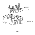
figure 6 est une vue en perspective, illustrant le support à glissières précité et le socle de l'appareil dans lequel ce support est destiné à être fixé, et - La
figure 7 est une vue en perspective du dit support à glissières, préalablement à sa mise en place dans le socle précité, - Sur la
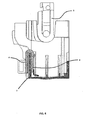
figure 1 , on voit un interrupteur différentiel I comportant principalement et de manière connue en soi, un mécanisme M d'ouverture et de fermeture de contacts, un tore 1 appartenant à la partie de l'appareil destinée à assurer la protection différentielle, un support 2 à glissières 3 destiné à recevoir les supports 4 de contact fixe et les supports de contact mobile, ledit support à glissières étant destiné à supporter également l'arbre de commande 9 des contacts et le mécanisme M de l'appareil. Une fois ces éléments montés sur le support 2 à glissières, les bornes d'entrée 5 de l'interrupteur I sont reliées électriquement aux contacts mobiles et les bornes de sortie 6 de l'interrupteur sont reliées aux extrémités libres des conducteurs primaires 7 (fig.1 ) sortant du tore 1, après quoi tout cet ensemble est monté à l'intérieur du socle S de l'appareil. - Afin d'éviter un mauvais positionnement du support 4 de contact fixe et de la corne d'arc 8 qui lui est associée dans les glissières 3 du support 2 à glissières, la corne d'arc 8 est fixée au support 4 du contact fixe par un procédé de fixation selon l'invention. Tel qu'illustré sur les
figures 2,3 et4 , le support 4 de contact fixe comporte une pièce en U dont l'une 10 des ailes 10,11 comporte sur sa face extérieure 10a un plot 12 en saillie et constituant une pastille de contact. La corne d'arc 8 est constituée principalement par une pièce en L, comportant une première partie 13 présentant une ouverture semi-circulaire 14 débouchant à l'extrémité libre de cette partie 13 et comportant à une extrémité opposée, une rainure 15, et une seconde partie 16 s'étendant sensiblement perpendiculairement à la première partie. La corne d'arc 8 est destinée à être fixée sur le support 4 de contact fixe par cette première partie 13 après le montage de l'ouverture semi-circulaire 14 de cette première partie autour du plot précité 12. A cet effet, selon une réalisation particulière de l'invention, deux orifices 17,18 dits premiers sont réalisés par perçage dans l'aile 10 du U du support 4 de contact fixe ainsi que deux orifices 19,20 dits seconds dans la première partie 13 de la corne d'arc 8. Sur la corne d'arc, ces orifices 19,20 sont placés de part et d'autre de la rainure précitée 15, ces deux orifices 19,20 étant destinés à être placés en regard des orifices 17,18 dits premiers situés sur l'aile 10 du support 4 de contact fixe. Les seconds orifices 19,20 présentent des dimensions plus petites que les premiers orifices 17,18. - Puis, on utilise deux poinçons afin de pousser la matière de la corne d'arc 8 dans les orifices 17,18 du support 4 de contact fixe, par leurs premières extrémités 17a,18a, ladite matière 21 étant plaquée contre la surface intérieure desdits premiers orifices 17,18 sans que la matière ne débouche à l'opposé desdits premiers orifices, par leurs extrémités opposées 17b,18b, tel que ceci est illustré sur la
figure 4 . - On réalise ainsi la fixation de la corne d'arc sur le support de contact fixe par accrochage, et/ou frottement et/ou arc-boutement de la matière de la corne d'arc sur la surface intérieure des orifices dits premiers orifices du support de contact fixe.
- Contrairement aux procédés habituels, la matière ne débouche pas et elle n'est pas repoussée sur les bords des orifices situés du côté opposé à la corne d'arc, afin d'assurer le maintien de la corne d'arc sur le support de contact fixe.
- Cette fixation est incomplète mais suffisante pour tenir les pièces ensemble pendant l'opération de tonnelage et pendant l'opération de montage de la corne d'arc et du support de contact fixe dans les glissières prévues dans l'interrupteur, tel qu'illustré sur la
figure 5 . - On a donc réalisé grâce à l'invention la fixation de la corne d'arc sur le support de contact fixe sans volume supplémentaire.
- C'est ainsi qu'une autre réalisation aurait pu consister à réaliser deux orifices dans le support et à ne pas réaliser de perçage dans la corne d'arc, mais à amener la matière de la corne d'arc dans les orifices du support par poinçonnage.
- Bien entendu, l'invention n'est pas limitée aux modes de réalisation décrits et illustrés qui n'ont été donnés qu'à titre d'exemple.
- Au contraire, l'invention comprend tous les équivalents techniques des moyens décrits ainsi que leurs combinaisons si celles-ci sont réalisées suivant son esprit.
Claims (6)
- Procédé de fixation d'une corne d'arc sur le support d'un contact fixe dans un appareil électrique de coupure, ledit support étant plié en forme de U, une pastille de contact étant fixée sur la surface extérieure de l'une des ailes du U précité,
caractérisé en ce que la corne d'arc précitée (8) comporte une ouverture (14) de forme semi-circulaire par laquelle ladite corne d'arc (8) peut être montée autour de la pastille de contact précitée (12), ladite pastille de contact (12) étant constituée par un plot en forme de disque en saillie sur ladite face extérieure (10a) de l'aile (10) du U, en ce que l'on réalise deux orifices dits premiers (17,18) dans le support (4) de contact fixe précité, puis on amène la corne d'arc (8) au-dessus du support de contact de telle manière que la corne d'arc soit montée autour du plot, et la matière (21) de la corne d'arc (8) est poussée, par poinçonnage, à l'intérieur des orifices dits premier(s) (17,18) en créant ainsi respectivement deux orifices dit seconds dans ladite corne d'arc, ladite matière étant introduite par l'une (17a,18a) des extrémités des premiers orifices, puis ladite matière étant plaquée contre la face intérieure desdits orifices dits premiers sans que la matière ne débouche desdits orifices dits premiers, par leurs extrémités opposées (17b,18b), la fixation du support (4) de contact fixe sur la corne d'arc (8) étant réalisée par accrochage et/ou frottage et/ou arc-boutage de la matière (21) de la corne d'arc (8) sur la face intérieure des orifices dits premiers (17,18) du support de contact (4). - Procédé de fixation selon la revendication 1, caractérisé en ce que l'on réalise un pré-perçage dans la corne d'arc (8) de manière à réaliser au moins un orifice(s) dit second(s) dans la corne d'arc, ledit(lesdits) second(s) orifice(s) étant de dimensions plus réduites que ledit(lesdits) premier(s) orifice(s), puis on amène la corne d'arc (8) au-dessus du support de contact en disposant l'(les) orifice(s) dit(s) premier(s) en regard de l' (des) orifice(s) dit(s) second(s), puis la matière (21) de la corne d'arc (8) est poussée, par poinçonnage, à l'intérieur de l'(des) orifice(s) dit(s) premier(s) (17,18) par l'une (17a,18a) de ses (de leurs) extrémité(s), et plaquée contre la face intérieure dudit(desdits) orifice(s) dit(s) premier(s) sans que la matière ne débouche dudit(desdits) orifice(s) dit(s) premier(s), par son (leurs) extrémité(s) opposée(s) (17b,18b), la fixation du support (4) de contact fixe sur la corne d'arc (8) étant réalisée par accrochage et/ou frottage et/ou arc-boutage de la matière (21) de la corne d'arc (8) sur la face intérieure des orifices dits premiers (17,18) du support de contact (4).
- Procédé de fixation selon la revendication 1 ou 2, caractérisé en ce que le nombre d'orifices dits premiers est de deux, de même que le nombre d'orifices dits seconds.
- Procédé de fixation selon l'une quelconque des revendications précédentes, caractérisé en ce que la corne d'arc (8) est fixée sur la face extérieure (10a) de l'aile (10) du U comportant la pastille de contact (12).
- Appareil de coupure électrique comportant un contact fixe et un contact mobile, lesdits contacts étant aptes à être fermés lors d'un fonctionnement normal de l'appareil et à être ouverts lors de l'apparition d'un incident sur la ligne électrique sur laquelle est placé l'appareil, ledit contact fixe comportant une pastille de contact (12) montée sur un support fixe (4), sur lequel support fixe est fixée une corne d'arc (8) selon le procédé de fixation selon l'une quelconque des revendications 1 à 4.
- Appareil de coupure électrique selon la revendication 5, caractérisé en ce que c'est un disjoncteur différentiel ou non, ou bien un interrupteur différentiel ou non.
Applications Claiming Priority (1)
| Application Number | Priority Date | Filing Date | Title |
|---|---|---|---|
| FR1004959A FR2969399B1 (fr) | 2010-12-20 | 2010-12-20 | Procede de fixation d'une corne d'arc sur un support de contact fixe dans un appareil de coupure electrique, et appareil electrique de coupure |
Publications (2)
| Publication Number | Publication Date |
|---|---|
| EP2466602A1 true EP2466602A1 (fr) | 2012-06-20 |
| EP2466602B1 EP2466602B1 (fr) | 2017-03-15 |
Family
ID=44263209
Family Applications (1)
| Application Number | Title | Priority Date | Filing Date |
|---|---|---|---|
| EP11354056.1A Active EP2466602B1 (fr) | 2010-12-20 | 2011-10-20 | Procédé de fixation d'une corne d'arc sur un support de contact fixe dans un appareil de coupure électrique, et appareil électrique de coupure |
Country Status (2)
| Country | Link |
|---|---|
| EP (1) | EP2466602B1 (fr) |
| FR (1) | FR2969399B1 (fr) |
Families Citing this family (1)
| Publication number | Priority date | Publication date | Assignee | Title |
|---|---|---|---|---|
| RU188118U1 (ru) * | 2017-09-22 | 2019-03-29 | Валерий Валерьевич Камаев | Механизм управления блокировкой тележки выдвижного элемента |
Citations (4)
| Publication number | Priority date | Publication date | Assignee | Title |
|---|---|---|---|---|
| FR2365874A1 (fr) * | 1976-09-28 | 1978-04-21 | Siemens Ag | Dispositif de contact pour disjoncteurs, en particulier pour disjoncteurs de protection de ligne |
| EP0079978A1 (fr) * | 1981-11-21 | 1983-06-01 | Sprecher & Schuh AG | Pièce de contact pour interrupteur électrique, en particulier pour interrupteur de protection |
| DE3728037A1 (de) * | 1987-08-22 | 1989-03-02 | No Sag Drahtfedern Gmbh | Verbindung zwischen zwei plattenfoermigen metallteilen |
| DE4018674A1 (de) * | 1989-10-04 | 1991-04-11 | Sprecher & Schuh Ag | Kontaktanordnung fuer ein elektrisches schaltgeraet, insbesondere fuer ein schuetz |
-
2010
- 2010-12-20 FR FR1004959A patent/FR2969399B1/fr active Active
-
2011
- 2011-10-20 EP EP11354056.1A patent/EP2466602B1/fr active Active
Patent Citations (4)
| Publication number | Priority date | Publication date | Assignee | Title |
|---|---|---|---|---|
| FR2365874A1 (fr) * | 1976-09-28 | 1978-04-21 | Siemens Ag | Dispositif de contact pour disjoncteurs, en particulier pour disjoncteurs de protection de ligne |
| EP0079978A1 (fr) * | 1981-11-21 | 1983-06-01 | Sprecher & Schuh AG | Pièce de contact pour interrupteur électrique, en particulier pour interrupteur de protection |
| DE3728037A1 (de) * | 1987-08-22 | 1989-03-02 | No Sag Drahtfedern Gmbh | Verbindung zwischen zwei plattenfoermigen metallteilen |
| DE4018674A1 (de) * | 1989-10-04 | 1991-04-11 | Sprecher & Schuh Ag | Kontaktanordnung fuer ein elektrisches schaltgeraet, insbesondere fuer ein schuetz |
Non-Patent Citations (2)
| Title |
|---|
| ANONYMOUS: "Clinchverfahren - TOX - Variopunkt II", INTERNET ARTICLE, 17 November 2008 (2008-11-17), XP002652539, Retrieved from the Internet <URL:http://web.archive.org/web/20080516050444/http://www.tox-de.com/produkte/verbindungstechnik/tox-clinch-verfahren/tox-variopunkt-ii.html> [retrieved on 20110721] * |
| KOHLMANN: "Eckold Clinching - The joining technique of the future for sheet metal and profiles", INTERNET ARTICLE, 6 October 2008 (2008-10-06), XP002652538, Retrieved from the Internet <URL:http://www.eckold.com/Portals/0/Content/PDF/PDF%20Clinchen/Eckold%20Clinching%20GB.pdf> [retrieved on 20110721] * |
Also Published As
| Publication number | Publication date |
|---|---|
| FR2969399B1 (fr) | 2013-03-08 |
| EP2466602B1 (fr) | 2017-03-15 |
| CN102568883A (zh) | 2012-07-11 |
| FR2969399A1 (fr) | 2012-06-22 |
Similar Documents
| Publication | Publication Date | Title |
|---|---|---|
| EP2867912B1 (fr) | Interrupteur électrique formant coupe-circuit à actionnement rapide | |
| EP1975971B1 (fr) | Dispositif de commande d'un appareil de protection électrique et appareil de protection électrique le comportant | |
| EP2458607B1 (fr) | Dispositif d'interverrouillage destiné à sécuriser l'accès à la boîte à câbles d'une cellule électrique et cellule électrique comportant un tel dispositif | |
| EP1796214B1 (fr) | Borne de connexion électrique et appareil électrique de coupure comportant une telle borne | |
| EP3109878B1 (fr) | Ampoule à vide et appareillage de protection électrique comportant une telle ampoule | |
| EP3487006B1 (fr) | Système électrique comprenant un appareil électrique et un module de connexion interchangeable | |
| EP2466602B1 (fr) | Procédé de fixation d'une corne d'arc sur un support de contact fixe dans un appareil de coupure électrique, et appareil électrique de coupure | |
| EP2456021A1 (fr) | Prise électrique comportant des montants latéraux mobiles en translation | |
| EP0758961B1 (fr) | Corps d'allumage pour allume-cigares, notamment de vehicule automobile | |
| FR2585198A3 (fr) | Porte-balai pour appareils electriques possedant des collecteurs, en particulier pour demarreurs, et application | |
| EP2061060B1 (fr) | Appareil électrique de coupure tel un disjoncteur ou un interrupteur | |
| EP3032562A1 (fr) | Dispositif de raccordement électrique comportant une sortie auxiliaire et appareil de commutation comportant un tel dispositif | |
| EP0773572A1 (fr) | Appareil électrique à enclenchement brusque | |
| EP0102867A1 (fr) | Dispositifs modulaires de limitation de courant | |
| FR2973559A1 (fr) | Pont de contact mobile | |
| FR2990793A1 (fr) | Disjoncteur a boitier moule | |
| FR2924531A1 (fr) | Dispositif de declenchement thermique pour appareil electrique de protection de ligne | |
| EP1683937A1 (fr) | Système de fermeture de porte d'enveloppe électrique | |
| EP1249849B1 (fr) | Appareil interrupteur électromagnétique à cassettes porte-contacts | |
| BE1004235A3 (fr) | Socle de prise de courant a obturateur escamotable et etanche. | |
| FR2626712A1 (fr) | Interrupteur electrique a coupure automatique, en particulier interrupteur differentiel | |
| EP3029704B1 (fr) | Disjoncteur différentiel | |
| EP3134910A1 (fr) | Dispositif a contact mobile sans tresse conductrice | |
| EP2575151A1 (fr) | Renforcement du mécanisme de sectionnement d'un appareil électrique multimodulaire du type disjoncteur. | |
| EP0108022A1 (fr) | Disjoncteur à sectionnement de neutre |
Legal Events
| Date | Code | Title | Description |
|---|---|---|---|
| PUAI | Public reference made under article 153(3) epc to a published international application that has entered the european phase |
Free format text: ORIGINAL CODE: 0009012 |
|
| AK | Designated contracting states |
Kind code of ref document: A1 Designated state(s): AL AT BE BG CH CY CZ DE DK EE ES FI FR GB GR HR HU IE IS IT LI LT LU LV MC MK MT NL NO PL PT RO RS SE SI SK SM TR |
|
| AX | Request for extension of the european patent |
Extension state: BA ME |
|
| 17P | Request for examination filed |
Effective date: 20121217 |
|
| 17Q | First examination report despatched |
Effective date: 20160302 |
|
| GRAP | Despatch of communication of intention to grant a patent |
Free format text: ORIGINAL CODE: EPIDOSNIGR1 |
|
| RIC1 | Information provided on ipc code assigned before grant |
Ipc: H01H 9/46 20060101AFI20161110BHEP Ipc: F16B 17/00 20060101ALI20161110BHEP Ipc: F16B 2/24 20060101ALN20161110BHEP |
|
| INTG | Intention to grant announced |
Effective date: 20161202 |
|
| GRAS | Grant fee paid |
Free format text: ORIGINAL CODE: EPIDOSNIGR3 |
|
| GRAA | (expected) grant |
Free format text: ORIGINAL CODE: 0009210 |
|
| AK | Designated contracting states |
Kind code of ref document: B1 Designated state(s): AL AT BE BG CH CY CZ DE DK EE ES FI FR GB GR HR HU IE IS IT LI LT LU LV MC MK MT NL NO PL PT RO RS SE SI SK SM TR |
|
| REG | Reference to a national code |
Ref country code: CH Ref legal event code: EP Ref country code: GB Ref legal event code: FG4D Free format text: NOT ENGLISH |
|
| REG | Reference to a national code |
Ref country code: IE Ref legal event code: FG4D Free format text: LANGUAGE OF EP DOCUMENT: FRENCH |
|
| REG | Reference to a national code |
Ref country code: AT Ref legal event code: REF Ref document number: 876332 Country of ref document: AT Kind code of ref document: T Effective date: 20170415 |
|
| REG | Reference to a national code |
Ref country code: DE Ref legal event code: R096 Ref document number: 602011035917 Country of ref document: DE |
|
| REG | Reference to a national code |
Ref country code: NL Ref legal event code: MP Effective date: 20170315 |
|
| REG | Reference to a national code |
Ref country code: LT Ref legal event code: MG4D |
|
| PG25 | Lapsed in a contracting state [announced via postgrant information from national office to epo] |
Ref country code: LT Free format text: LAPSE BECAUSE OF FAILURE TO SUBMIT A TRANSLATION OF THE DESCRIPTION OR TO PAY THE FEE WITHIN THE PRESCRIBED TIME-LIMIT Effective date: 20170315 Ref country code: GR Free format text: LAPSE BECAUSE OF FAILURE TO SUBMIT A TRANSLATION OF THE DESCRIPTION OR TO PAY THE FEE WITHIN THE PRESCRIBED TIME-LIMIT Effective date: 20170616 Ref country code: FI Free format text: LAPSE BECAUSE OF FAILURE TO SUBMIT A TRANSLATION OF THE DESCRIPTION OR TO PAY THE FEE WITHIN THE PRESCRIBED TIME-LIMIT Effective date: 20170315 Ref country code: HR Free format text: LAPSE BECAUSE OF FAILURE TO SUBMIT A TRANSLATION OF THE DESCRIPTION OR TO PAY THE FEE WITHIN THE PRESCRIBED TIME-LIMIT Effective date: 20170315 Ref country code: NO Free format text: LAPSE BECAUSE OF FAILURE TO SUBMIT A TRANSLATION OF THE DESCRIPTION OR TO PAY THE FEE WITHIN THE PRESCRIBED TIME-LIMIT Effective date: 20170615 |
|
| REG | Reference to a national code |
Ref country code: AT Ref legal event code: MK05 Ref document number: 876332 Country of ref document: AT Kind code of ref document: T Effective date: 20170315 |
|
| PG25 | Lapsed in a contracting state [announced via postgrant information from national office to epo] |
Ref country code: RS Free format text: LAPSE BECAUSE OF FAILURE TO SUBMIT A TRANSLATION OF THE DESCRIPTION OR TO PAY THE FEE WITHIN THE PRESCRIBED TIME-LIMIT Effective date: 20170315 Ref country code: BG Free format text: LAPSE BECAUSE OF FAILURE TO SUBMIT A TRANSLATION OF THE DESCRIPTION OR TO PAY THE FEE WITHIN THE PRESCRIBED TIME-LIMIT Effective date: 20170615 Ref country code: LV Free format text: LAPSE BECAUSE OF FAILURE TO SUBMIT A TRANSLATION OF THE DESCRIPTION OR TO PAY THE FEE WITHIN THE PRESCRIBED TIME-LIMIT Effective date: 20170315 Ref country code: SE Free format text: LAPSE BECAUSE OF FAILURE TO SUBMIT A TRANSLATION OF THE DESCRIPTION OR TO PAY THE FEE WITHIN THE PRESCRIBED TIME-LIMIT Effective date: 20170315 |
|
| PG25 | Lapsed in a contracting state [announced via postgrant information from national office to epo] |
Ref country code: NL Free format text: LAPSE BECAUSE OF FAILURE TO SUBMIT A TRANSLATION OF THE DESCRIPTION OR TO PAY THE FEE WITHIN THE PRESCRIBED TIME-LIMIT Effective date: 20170315 |
|
| REG | Reference to a national code |
Ref country code: FR Ref legal event code: PLFP Year of fee payment: 7 |
|
| PG25 | Lapsed in a contracting state [announced via postgrant information from national office to epo] |
Ref country code: SK Free format text: LAPSE BECAUSE OF FAILURE TO SUBMIT A TRANSLATION OF THE DESCRIPTION OR TO PAY THE FEE WITHIN THE PRESCRIBED TIME-LIMIT Effective date: 20170315 Ref country code: EE Free format text: LAPSE BECAUSE OF FAILURE TO SUBMIT A TRANSLATION OF THE DESCRIPTION OR TO PAY THE FEE WITHIN THE PRESCRIBED TIME-LIMIT Effective date: 20170315 Ref country code: ES Free format text: LAPSE BECAUSE OF FAILURE TO SUBMIT A TRANSLATION OF THE DESCRIPTION OR TO PAY THE FEE WITHIN THE PRESCRIBED TIME-LIMIT Effective date: 20170315 Ref country code: AT Free format text: LAPSE BECAUSE OF FAILURE TO SUBMIT A TRANSLATION OF THE DESCRIPTION OR TO PAY THE FEE WITHIN THE PRESCRIBED TIME-LIMIT Effective date: 20170315 Ref country code: IT Free format text: LAPSE BECAUSE OF FAILURE TO SUBMIT A TRANSLATION OF THE DESCRIPTION OR TO PAY THE FEE WITHIN THE PRESCRIBED TIME-LIMIT Effective date: 20170315 Ref country code: RO Free format text: LAPSE BECAUSE OF FAILURE TO SUBMIT A TRANSLATION OF THE DESCRIPTION OR TO PAY THE FEE WITHIN THE PRESCRIBED TIME-LIMIT Effective date: 20170315 Ref country code: CZ Free format text: LAPSE BECAUSE OF FAILURE TO SUBMIT A TRANSLATION OF THE DESCRIPTION OR TO PAY THE FEE WITHIN THE PRESCRIBED TIME-LIMIT Effective date: 20170315 |
|
| PG25 | Lapsed in a contracting state [announced via postgrant information from national office to epo] |
Ref country code: PL Free format text: LAPSE BECAUSE OF FAILURE TO SUBMIT A TRANSLATION OF THE DESCRIPTION OR TO PAY THE FEE WITHIN THE PRESCRIBED TIME-LIMIT Effective date: 20170315 Ref country code: IS Free format text: LAPSE BECAUSE OF FAILURE TO SUBMIT A TRANSLATION OF THE DESCRIPTION OR TO PAY THE FEE WITHIN THE PRESCRIBED TIME-LIMIT Effective date: 20170715 Ref country code: SM Free format text: LAPSE BECAUSE OF FAILURE TO SUBMIT A TRANSLATION OF THE DESCRIPTION OR TO PAY THE FEE WITHIN THE PRESCRIBED TIME-LIMIT Effective date: 20170315 Ref country code: PT Free format text: LAPSE BECAUSE OF FAILURE TO SUBMIT A TRANSLATION OF THE DESCRIPTION OR TO PAY THE FEE WITHIN THE PRESCRIBED TIME-LIMIT Effective date: 20170717 |
|
| REG | Reference to a national code |
Ref country code: DE Ref legal event code: R097 Ref document number: 602011035917 Country of ref document: DE |
|
| PLBE | No opposition filed within time limit |
Free format text: ORIGINAL CODE: 0009261 |
|
| STAA | Information on the status of an ep patent application or granted ep patent |
Free format text: STATUS: NO OPPOSITION FILED WITHIN TIME LIMIT |
|
| PG25 | Lapsed in a contracting state [announced via postgrant information from national office to epo] |
Ref country code: DK Free format text: LAPSE BECAUSE OF FAILURE TO SUBMIT A TRANSLATION OF THE DESCRIPTION OR TO PAY THE FEE WITHIN THE PRESCRIBED TIME-LIMIT Effective date: 20170315 |
|
| 26N | No opposition filed |
Effective date: 20171218 |
|
| PG25 | Lapsed in a contracting state [announced via postgrant information from national office to epo] |
Ref country code: SI Free format text: LAPSE BECAUSE OF FAILURE TO SUBMIT A TRANSLATION OF THE DESCRIPTION OR TO PAY THE FEE WITHIN THE PRESCRIBED TIME-LIMIT Effective date: 20170315 |
|
| PG25 | Lapsed in a contracting state [announced via postgrant information from national office to epo] |
Ref country code: MC Free format text: LAPSE BECAUSE OF FAILURE TO SUBMIT A TRANSLATION OF THE DESCRIPTION OR TO PAY THE FEE WITHIN THE PRESCRIBED TIME-LIMIT Effective date: 20170315 |
|
| REG | Reference to a national code |
Ref country code: CH Ref legal event code: PL |
|
| GBPC | Gb: european patent ceased through non-payment of renewal fee |
Effective date: 20171020 |
|
| REG | Reference to a national code |
Ref country code: IE Ref legal event code: MM4A |
|
| PG25 | Lapsed in a contracting state [announced via postgrant information from national office to epo] |
Ref country code: GB Free format text: LAPSE BECAUSE OF NON-PAYMENT OF DUE FEES Effective date: 20171020 Ref country code: CH Free format text: LAPSE BECAUSE OF NON-PAYMENT OF DUE FEES Effective date: 20171031 Ref country code: LU Free format text: LAPSE BECAUSE OF NON-PAYMENT OF DUE FEES Effective date: 20171020 Ref country code: LI Free format text: LAPSE BECAUSE OF NON-PAYMENT OF DUE FEES Effective date: 20171031 |
|
| REG | Reference to a national code |
Ref country code: BE Ref legal event code: MM Effective date: 20171031 |
|
| PG25 | Lapsed in a contracting state [announced via postgrant information from national office to epo] |
Ref country code: BE Free format text: LAPSE BECAUSE OF NON-PAYMENT OF DUE FEES Effective date: 20171031 |
|
| PG25 | Lapsed in a contracting state [announced via postgrant information from national office to epo] |
Ref country code: MT Free format text: LAPSE BECAUSE OF FAILURE TO SUBMIT A TRANSLATION OF THE DESCRIPTION OR TO PAY THE FEE WITHIN THE PRESCRIBED TIME-LIMIT Effective date: 20170315 |
|
| PG25 | Lapsed in a contracting state [announced via postgrant information from national office to epo] |
Ref country code: IE Free format text: LAPSE BECAUSE OF NON-PAYMENT OF DUE FEES Effective date: 20171020 |
|
| PG25 | Lapsed in a contracting state [announced via postgrant information from national office to epo] |
Ref country code: HU Free format text: LAPSE BECAUSE OF FAILURE TO SUBMIT A TRANSLATION OF THE DESCRIPTION OR TO PAY THE FEE WITHIN THE PRESCRIBED TIME-LIMIT; INVALID AB INITIO Effective date: 20111020 |
|
| PG25 | Lapsed in a contracting state [announced via postgrant information from national office to epo] |
Ref country code: CY Free format text: LAPSE BECAUSE OF NON-PAYMENT OF DUE FEES Effective date: 20170315 |
|
| PG25 | Lapsed in a contracting state [announced via postgrant information from national office to epo] |
Ref country code: MK Free format text: LAPSE BECAUSE OF FAILURE TO SUBMIT A TRANSLATION OF THE DESCRIPTION OR TO PAY THE FEE WITHIN THE PRESCRIBED TIME-LIMIT Effective date: 20170315 |
|
| PG25 | Lapsed in a contracting state [announced via postgrant information from national office to epo] |
Ref country code: TR Free format text: LAPSE BECAUSE OF FAILURE TO SUBMIT A TRANSLATION OF THE DESCRIPTION OR TO PAY THE FEE WITHIN THE PRESCRIBED TIME-LIMIT Effective date: 20170315 |
|
| PG25 | Lapsed in a contracting state [announced via postgrant information from national office to epo] |
Ref country code: AL Free format text: LAPSE BECAUSE OF FAILURE TO SUBMIT A TRANSLATION OF THE DESCRIPTION OR TO PAY THE FEE WITHIN THE PRESCRIBED TIME-LIMIT Effective date: 20170315 |
|
| PGFP | Annual fee paid to national office [announced via postgrant information from national office to epo] |
Ref country code: DE Payment date: 20241029 Year of fee payment: 14 |
|
| PGFP | Annual fee paid to national office [announced via postgrant information from national office to epo] |
Ref country code: FR Payment date: 20241025 Year of fee payment: 14 |