EP2466552A1 - Système d'information à bord doté d'une antenne mobile - Google Patents
Système d'information à bord doté d'une antenne mobile Download PDFInfo
- Publication number
- EP2466552A1 EP2466552A1 EP11191192A EP11191192A EP2466552A1 EP 2466552 A1 EP2466552 A1 EP 2466552A1 EP 11191192 A EP11191192 A EP 11191192A EP 11191192 A EP11191192 A EP 11191192A EP 2466552 A1 EP2466552 A1 EP 2466552A1
- Authority
- EP
- European Patent Office
- Prior art keywords
- housing
- mobile radio
- radio antenna
- antenna
- information system
- Prior art date
- Legal status (The legal status is an assumption and is not a legal conclusion. Google has not performed a legal analysis and makes no representation as to the accuracy of the status listed.)
- Granted
Links
- 238000009434 installation Methods 0.000 claims description 17
- PEZNEXFPRSOYPL-UHFFFAOYSA-N (bis(trifluoroacetoxy)iodo)benzene Chemical compound FC(F)(F)C(=O)OI(OC(=O)C(F)(F)F)C1=CC=CC=C1 PEZNEXFPRSOYPL-UHFFFAOYSA-N 0.000 claims description 4
- 239000003989 dielectric material Substances 0.000 claims description 3
- 230000005540 biological transmission Effects 0.000 description 5
- 239000004020 conductor Substances 0.000 description 4
- 238000011161 development Methods 0.000 description 4
- 230000018109 developmental process Effects 0.000 description 4
- 230000010354 integration Effects 0.000 description 3
- 238000004026 adhesive bonding Methods 0.000 description 2
- 230000001413 cellular effect Effects 0.000 description 2
- 230000000694 effects Effects 0.000 description 2
- 239000002184 metal Substances 0.000 description 2
- 210000002105 tongue Anatomy 0.000 description 2
- 238000004891 communication Methods 0.000 description 1
- 230000008878 coupling Effects 0.000 description 1
- 238000010168 coupling process Methods 0.000 description 1
- 238000005859 coupling reaction Methods 0.000 description 1
- 238000001514 detection method Methods 0.000 description 1
- 238000004519 manufacturing process Methods 0.000 description 1
- 230000007246 mechanism Effects 0.000 description 1
- 238000010295 mobile communication Methods 0.000 description 1
- 239000012811 non-conductive material Substances 0.000 description 1
- 230000005855 radiation Effects 0.000 description 1
- 238000005476 soldering Methods 0.000 description 1
Images


Classifications
-
- H—ELECTRICITY
- H04—ELECTRIC COMMUNICATION TECHNIQUE
- H04B—TRANSMISSION
- H04B1/00—Details of transmission systems, not covered by a single one of groups H04B3/00 - H04B13/00; Details of transmission systems not characterised by the medium used for transmission
-
- G—PHYSICS
- G07—CHECKING-DEVICES
- G07C—TIME OR ATTENDANCE REGISTERS; REGISTERING OR INDICATING THE WORKING OF MACHINES; GENERATING RANDOM NUMBERS; VOTING OR LOTTERY APPARATUS; ARRANGEMENTS, SYSTEMS OR APPARATUS FOR CHECKING NOT PROVIDED FOR ELSEWHERE
- G07C7/00—Details or accessories common to the registering or indicating apparatus of groups G07C3/00 and G07C5/00
-
- H—ELECTRICITY
- H01—ELECTRIC ELEMENTS
- H01Q—ANTENNAS, i.e. RADIO AERIALS
- H01Q1/00—Details of, or arrangements associated with, antennas
- H01Q1/12—Supports; Mounting means
- H01Q1/22—Supports; Mounting means by structural association with other equipment or articles
- H01Q1/24—Supports; Mounting means by structural association with other equipment or articles with receiving set
-
- H—ELECTRICITY
- H01—ELECTRIC ELEMENTS
- H01Q—ANTENNAS, i.e. RADIO AERIALS
- H01Q9/00—Electrically-short antennas having dimensions not more than twice the operating wavelength and consisting of conductive active radiating elements
- H01Q9/04—Resonant antennas
- H01Q9/0407—Substantially flat resonant element parallel to ground plane, e.g. patch antenna
- H01Q9/0421—Substantially flat resonant element parallel to ground plane, e.g. patch antenna with a shorting wall or a shorting pin at one end of the element
Definitions
- the present invention relates to an on-board information system with a mobile radio antenna for detecting at least one vehicle-relevant variable.
- On-board information systems in particular tachographs, toll collection devices or so-called universal onboard units, which combine the functions of tachographs and toll collection devices, must meet increasingly stringent technical requirements.
- the coupling of such a device with a device for receiving mobile radio offers new applications that allow improved communication between a built in a vehicle, such as a truck, on-board information system and various transmitters or receivers.
- EP 1 538 572 A2 a road user registration device, in which the detection device can be inserted into the housing of a digital tachograph and can transmit data to an external receiver via a mobile radio module.
- a disadvantage of the prior art is that while a mobile radio receiver may be integrated into a housing of an on-board information system, a mobile radio antenna is usually mounted outside the housing at a different position of the vehicle in order to ensure a sufficiently strong reception. Electrically conductive parts of the housing can influence the mobile radio antenna during reception and transmission in such a way that the signal strength at the mobile radio antenna is too low.
- An attachment of the mobile antenna outside the housing is also disadvantageous, since this addition to a mounting of the mobile antenna an additional wired or wireless Connection between the mobile antenna and housed in the housing of the onboard information system mobile communication module must be made.
- the mobile radio antenna In order to install a mobile radio antenna in an interior of a vehicle, the mobile radio antenna may not have too large dimensions and must show a very good transmitting and receiving performance, which is not reduced by other components.
- the present invention is therefore based on the object to develop an on-board information system which avoids the disadvantages mentioned.
- An on-board information system which is designed to detect at least one vehicle-relevant variable, comprises a housing which can be installed in a vehicle interior, a mobile radio module and a mobile radio antenna, wherein the mobile radio antenna is placed in a recess of the housing.
- the radiating surface of the mobile radio antenna is hereby spaced from the housing.
- the recess serves to receive the mobile radio antenna in such a way that no edges of the mobile radio antenna protrude, but a conclusion as flush as possible with the rest of the housing is achieved.
- the mobile radio antenna is thus positioned on the one hand on the housing of the on-board information system, so that the placement of the mobile radio antenna in the recess of the housing forms a compact unit that is easy to install in the vehicle interior.
- by spacing a radiating surface from the housing it is achieved that the radiating and receiving characteristic of the mobile radio antenna is good enough Even with a build-up within the vehicle interior to provide sufficient performance.
- Opposite known from the prior art on-board information systems offers a solution of the invention has the advantage to combine all required for the reception of mobile components in a housing, so that the resulting unit is easily and quickly in vehicles and expandable and at the mobile antenna no longer must be positioned separately at a different position of the vehicle.
- an electrically conductive component of the housing of the on-board information system and the radiating surface of the mobile radio antenna can have a distance of at least 50% of an overall height of the mobile radio antenna.
- the distance of the radiating surface of the mobile radio antenna to an electrically conductive component is at least 100% of the total height of the mobile radio antenna. This distance of at least 50% of the total height of the mobile radio antenna ensures that the mobile radio antenna is still compact with the housing can be built, since the dimensions are kept small, but also a sufficient distance to electrically conductive components of the housing, which is the performance of the mobile antenna influence negatively.
- a further advantageous embodiment provides that the mobile radio antenna in the form of a PIFA antenna, so a "Planar Inverted F-Shaped Antenna" may be present.
- a PIFA antenna generally has a flat configuration consisting of a radiating surface and a ground plane arranged substantially parallel thereto, which are connected to one another by a short-circuit connection, as well as a feed line for the radiating surface.
- Such antennas have a very good performance with low manufacturing and installation costs, at the same time are the common dimensions of such an antenna suitable for installation in a vehicle interior.
- the mobile radio antenna can be mounted on an outer side of the housing.
- the mobile radio antenna can be connected directly to the housing.
- the recess for receiving the mobile radio antenna advantageously has a substantially closed surface.
- the mobile radio antenna can be easily mounted on the housing.
- a hole in the surface of the housing may be provided for the recess.
- the mobile radio antenna may have dimensions which are smaller or equal dimensions of the recess of the housing.
- the mobile radio antenna terminates flush with the housing without affecting its dimensions.
- a further advantageous embodiment provides that one foot of the mobile radio antenna can be connected to an electrically conductive part of the housing.
- the foot of the mobile radio antenna which is designed as a non-radiating part of the antenna, can thus be connected very well flat with an electrical ground of the housing and thus the mobile radio antenna can develop its full power.
- the bearing surface of the foot on the case and the foot itself can be used in particular advantageously have approximately the same size, which allows a particularly space-saving positioning.
- an attachment of the mobile radio antenna directly on the housing is advantageous, since thus no antenna power is absorbed by the housing.
- the mobile radio antenna can be mounted on a side of the housing facing away from the vehicle interior after installation.
- space is created for an operating unit on the side of the housing facing the vehicle interior, while at the same time the mobile radio antenna is integrated.
- the housing may have a cover of dielectric material, for example a plastic.
- the housing is protected against mechanical damage, but at the same time ensured by the dielectric material that there is no shielding by a conductive material.
- the mobile radio antenna can be protected by such a cover, without affecting the transmission and reception performance.
- the cover can ensure that the housing and cover flush and thus form a compact unit that can be easily installed without obstruction by protruding parts or edges.
- a further advantageous embodiment provides that the housing can be installed in a shaft with dimensions according to a standard ISO 7736.
- the housing corresponds to a standard size for installation in consoles of a vehicle, for example in a radio tray.
- the housing of the on-board information system can thus be easily and easily installed in models from different manufacturers.
- the mobile radio antenna can be connected to a cable, in particular a coaxial cable, wherein the cable can be guided by a recess located in the foot of the mobile radio antenna in the housing.
- an on-board information system with the features mentioned in a vehicle can be used as a tachograph, in particular as a digital tachograph, and / or as a toll collection device, wherein a combination of the features of tachograph and toll collection device is referred to by a universal onboard unit.
- a technical extension of these devices is achieved.
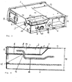
- Fig. 1 represents a housing 1 of a board information system according to the invention in a perspective rear view, ie the side of the housing 1 shown is facing away from an installation a vehicle interior or covered by a drive bay.
- the onboard information system is a digital tachograph in the case shown, but it can also be designed as a conventional tachograph, toll collection device or as a universal onboard unit.
- the installation can be carried out in different vehicle types, both in passenger cars and in trucks.
- the dimensions of the housing 1 are selected according to a standard ISO 7736 or DIN 75490, so that installation in shafts, such as radio shafts in the instrument panel of a vehicle, is easily possible with a variety of models from different manufacturers.
- the housing 1 consists of a conductive material, in the present case a metal, and has a recess 3 on an upper side 13 of an outer side 7.
- the housing 1 may also consist of an electrically non-conductive material.
- a housing height 18 is 50 mm in the illustrated embodiment.
- the housing 1 has a continuous surface, which is integrally connected to the housing 1.
- the recess 3 has a bearing surface 17 arranged parallel to an upper side 13 of the housing 1 for a foot of a mobile radio antenna, which is connected to the upper side 13 of the housing 1 by beveled flanks.
- the recess 3 has beveled edges, on the one hand to ensure a sufficient distance between a mobile radio antenna and the housing 1. On the other hand, space is still provided by the bevelled edges in the interior of the housing 1 for the installation of further modules or components.
- the flanks extend in the embodiment shown at an angle of 45 °, but there are other angles, preferably in the range between 30 ° and 60 °, possible.
- the recess 3 is located at the edge of the housing 1, but the recess 3 can also be located centrally in the housing 1.
- the recess 3 may also be parallelepiped-shaped, that is to say have no beveled flanks or alternatively also have a bevelled flank on at least one side and a right-angled flank on at least one other side.
- a single section of the housing 1 in the form of a hole is included as a recess 3 of the invention, in which case a mobile radio antenna is placed in the resulting recess.
- the on-board information system also comprises a mobile radio module, which in Fig. 1 is not shown, since it is located in the interior of the housing 1 and is covered by this.
- the recess 3 is excluded from an upper side 13 of the housing 1, but can also on a in Fig. 1 not visible underside lie.
- the surface of the recess 3 is formed as a closed surface, wherein the support surface 17 of a mobile radio antenna has the same dimensions as a foot of a mobile radio antenna, the dimensions may also be larger than an antenna base.
- a mobile radio antenna is facing away from the vehicle interior after installation Side mounted to allow the installation of display and control elements at the front, however, the recess 3 for a mobile radio antenna can be made at any position of the housing 1, ie also on a vehicle interior facing side.
- the recess 3 contains a passage 14, by means of which a mobile radio antenna placed in the recess 3 can be connected to components integrated in the interior of the housing 1.
- the recess 3 has at least one receptacle 15 for connecting a cover 9 to the recess 3.
- a plurality of receptacles 15 are included for better attachment.
- the receptacles 15 are designed in the illustrated case for receiving locking tongues of a cover 9, but it can also be provided a screw for fixing the cover 9 with the housing 1.
- the receptacles 15 have a maximum distance of 50 mm in order to avoid long edges, since these edges act as antennas and thus can interfere with the reception of the mobile radio antenna 2.
- the housing 1 has at least one outbreak 16 for attaching the housing 1 to a fastening device of the vehicle interior, for example by screwing a threaded bolt, or for electrical contact with other components positioned in the vehicle interior.
- Fig. 2 an embodiment of a mobile radio antenna 2 is shown.
- the mobile radio antenna 2 is designed as a PIFA antenna, that is to say as a "Planar Inverted F-Shaped Antenna".
- a radiating surface 4 with a foot 8 is electrically connected by a connecting element 12, which serves as a short-circuit line.
- Radiant surface 4 and foot 8 are arranged parallel to each other, a Total height 6 results as a distance between an upper side of the radiating surface 4 and an underside of the foot 8 which is not visible here.
- the mobile radio antenna 2 is made of an electrically conductive material, in particular a metal.
- the mobile phone antenna which can be inserted into the recess 3 can also be realized in a different design, for example as a patch antenna.
- the mobile radio antenna 2 As a feed line or for connection to the mobile radio module or other modules that may be placed in the housing 1, the mobile radio antenna 2 comprises a cable 10, in this case a coaxial cable, which is guided by a recess 11 contained in the foot 8 of the mobile radio antenna 2 becomes.
- the cable 10 can be soldered, screwed or clamped to the mobile radio antenna 2, in particular to the connecting element 12 or the radiating surface 4.
- a recess 11 corresponding to implementation 14 for the cable 10 is included on the surface of the recess 3, a recess 11 corresponding to implementation 14 for the cable 10 is included.
- the recess 11 may, as in the case shown, be a hole in the foot 8, but also a recess on an edge of the foot 8.
- the recess 11 is only slightly larger in diameter than the diameter of the cable 10 and of smaller or equal diameter the implementation 14. If the diameter of the bushing 14 is greater than the diameter of the recess 11, for example, an antenna plug can be pushed through to one end of the cable 10.
- the performance of the mobile antenna 2 is increased, while the cable 10 almost completely fills the larger recess 11 and thus no negative effect on the performance takes place as a not filled by the cable 10 part of the recess 14 is covered by the foot 8.
- This design increases the performance of the mobile radio antenna 2, while the cable 10 almost completely fills the only slightly larger recess 11 and thus there is no negative effect on the power.
- the mobile radio antenna 2 is suitable for receiving various mobile radio signals, for example signals according to the GSM, the GPRS, the UMTS or another standard.
- the dimensions of the mobile radio antenna 2 are smaller than or equal to the dimensions of the recess 3. This ensures that the mobile antenna 2 does not protrude from the housing 1 and thus installation in the vehicle interior can be made easier.
- Fig. 3 is the in Fig. 2 shown mobile radio antenna 2 on an outer side 7 of in Fig. 1 shown housing 1 of the onboard information system mounted in the recess 3.
- the foot 8 of the mobile radio antenna 2 is in this case connected in a planar manner to the outside 7 of the housing 1, so that a ground connection between the base 8 serving as the ground surface of the mobile radio antenna 2 and a ground surface of the housing 1, which is given by the electrically conductive outer side 7 of the housing 1 , is ensured.
- the cable 10 is guided through the recess 11 and the passage 14 into the interior of the housing 1.
- the connection of the antenna can be done by riveting, soldering, screwing or gluing.
- the dimensions of the mobile radio antenna 2 are smaller or equal to the dimensions of the recess 3.
- the housing 1 can be installed in a shaft with dimensions according to ISO 7736 or DIN 75490.
- the upper side of the radiating surface 4 is at the same height as the upper side 13 of the housing 1 or slightly below the upper side 13.
- the radiating surface 4 of the mobile radio antenna 2 is mounted at a distance 5 from the surface of the recess 3.
- the distance 5 is in the illustrated case about 100% of the total height 6 of the mobile radio antenna 2, so that radiation is not hindered and is the same on both the longitudinal and on the transverse side of the radiating surface 4.
- the distance 5 does not have to be the same on all sides, provided that in each case the said minimum distance is not undershot. Consequently a higher variability in the integration of other modules in the interior of the housing 1 is achieved.
- the foot 8 covers with its surface from the bushing 14 in the housing 1, so that the performance of the mobile antenna 2 is not degraded by a larger diameter of the bushing 14 than the diameter of the recess 11.
- the radiating surface 4 of the mobile antenna 2 on the one hand does not protrude beyond the dimensions of the housing 1, to ensure easy installation, but on the other hand, a sufficient distance. 5 to an electrically conductive part of the housing 1 and a positioning as close as possible to the outside 7 of the housing 1 has.
- a correspondingly good transmission and reception characteristics of the mobile radio antenna 2 is achieved in a compact design.
- Fig. 4 is a section through the housing 1 parallel to the back of the housing 1 shown.
- the cable 10 is connected to the mobile radio antenna 2 and is guided through a recess 11 in the foot 8 of the mobile radio antenna 2 and the bushing 14 into the interior of the housing 1.
- the recess 3 has chamfered flanks, to ensure a distance 5, which, as already explained, about 100% of the total height 6 of the mobile radio antenna 2, between the radiating surface 4 and the housing 1.
- the foot 8 of the mobile radio antenna 2 is mounted flush with a surface of the recess 3.
- the dimensions of the foot 8 and the bearing surface of the foot 8 on the recess 3 have substantially the same size on. As a result, a good contact can be realized in a small footprint.
- the mobile radio antenna 2 is protected by a cover 9 against mechanical damage.
- the cover 9 has locking tongues, which are introduced into the receptacles 15 and engage therein.
- a reliable connection can be made, the cover 9 can also be easily solved.
- an attachment of the cover 9 by screws, a magnetic connection, gluing, riveting or other connection mechanisms may be provided.
- the rest of the housing 1 can be protected by a cover against mechanical damage.
- the cover 9 is made of a dielectric, that is not or only weakly electrically conductive material, in the present case of plastic, in order to avoid a negative influence on the transmission and reception characteristics of the mobile radio antenna 2.
- the cover 9 touches in the illustrated embodiment, the radiating surface 4 of the mobile radio antenna 2, but it is also conceivable to allow a gap between the two parts.
- the cover 9 continues the upper side 13 of the housing 1 flush, so that a flat surface is formed, but the cover 9 can also be below the upper side 13 of the housing 1, so that a step or slope between the cover 9 and top 13 is formed. This results in a substantially cuboid housing 1 with cover 9, which is easy to install and remove.
- Fig. 5 shows a section through the housing 1 perpendicular to the back of the housing 1. Also in this figure, the distance 5 between radiating surface 4 and housing 1, in particular an electrically conductive component of the housing 1, about 100% of the total height 6 of the mobile antenna. 2
- the cable 10 is in direct contact with a connecting element 12 between radiating surface 4 and foot 8 and is guided by the recess 11 located on this connecting element 12 into the interior of the housing 1.
- the cover 9 in turn covers the entire recess 3, including the mobile radio antenna 2, thus ensuring a flush connection to the outside 7 of the housing 1.
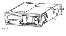
- Fig. 6 is from the same perspective as in Fig. 1 the housing 1 of the onboard information system shown.
- the mobile radio antenna 2 is now hidden under the cover 9.
- the cover 9 provides a flush connection to the shape of the housing 1, so that even with cover 9, the dimensions are suitable for installation in a shaft according to ISO 7736 or DIN 75490.
- the distance between the cellular antenna 2 and other electrically conductive parts of other built-in devices that may cover the cellular antenna 2 should be at least 20 mm to provide sufficient signals receive and send.
- Fig. 7 shows the front, so after installation a vehicle interior facing side of in Fig. 6 in a rear view illustrated housing 1 of the onboard information system.
- a housing 1 with integrated mobile radio antenna 2 of an on-board information system it is possible to obtain a compact housing 1 suitable for installation in different vehicle types without the installation of additional modules or external antennas.
- an exchange by the standard dimensions can be carried out easily and quickly.
Landscapes
- Physics & Mathematics (AREA)
- General Physics & Mathematics (AREA)
- Engineering & Computer Science (AREA)
- Computer Networks & Wireless Communication (AREA)
- Signal Processing (AREA)
- Support Of Aerials (AREA)
- Fittings On The Vehicle Exterior For Carrying Loads, And Devices For Holding Or Mounting Articles (AREA)
Applications Claiming Priority (1)
| Application Number | Priority Date | Filing Date | Title |
|---|---|---|---|
| DE102010055206A DE102010055206A1 (de) | 2010-12-20 | 2010-12-20 | Bordinformationssystem mit Mobilfunkantenne |
Publications (2)
| Publication Number | Publication Date |
|---|---|
| EP2466552A1 true EP2466552A1 (fr) | 2012-06-20 |
| EP2466552B1 EP2466552B1 (fr) | 2018-07-25 |
Family
ID=45217305
Family Applications (1)
| Application Number | Title | Priority Date | Filing Date |
|---|---|---|---|
| EP11191192.1A Active EP2466552B1 (fr) | 2010-12-20 | 2011-11-29 | Système d'information à bord doté d'une antenne mobile |
Country Status (6)
| Country | Link |
|---|---|
| US (1) | US20120188132A1 (fr) |
| EP (1) | EP2466552B1 (fr) |
| CN (1) | CN102542633A (fr) |
| BR (1) | BRPI1106966B1 (fr) |
| DE (1) | DE102010055206A1 (fr) |
| RU (1) | RU2599617C2 (fr) |
Families Citing this family (6)
| Publication number | Priority date | Publication date | Assignee | Title |
|---|---|---|---|---|
| US20140011465A1 (en) * | 2012-07-05 | 2014-01-09 | Delphi Technologies, Inc. | Molded conductive plastic antenna |
| CN103345783A (zh) * | 2013-06-28 | 2013-10-09 | 成都众易通科技有限公司 | 一种方便对排布线路的行驶记录仪的壳体结构 |
| JP6503911B2 (ja) | 2015-06-17 | 2019-04-24 | マツダ株式会社 | 車両用情報通信システム |
| KR101892027B1 (ko) | 2016-05-18 | 2018-08-27 | 현대자동차주식회사 | 내장형 rf 안테나를 구비한 dtg 장치 |
| EP4071930A1 (fr) | 2021-04-08 | 2022-10-12 | Continental Automotive Technologies GmbH | Ensemble antenne et véhicule |
| DE102022201514A1 (de) * | 2022-02-14 | 2023-08-17 | Continental Automotive Technologies GmbH | Stabförmige Kommunikationseinheit und Tachographensystem mit einer Kommunikationseinheit |
Citations (7)
| Publication number | Priority date | Publication date | Assignee | Title |
|---|---|---|---|---|
| EP0604338A1 (fr) * | 1992-12-23 | 1994-06-29 | France Telecom | Antenne large bande à encombrement réduit, et dispositf d'émission/réception correspondant |
| DE20108778U1 (de) * | 2001-05-25 | 2001-08-02 | Mannesmann Vdo Ag | Gehäuse für ein in einem Fahrzeug verwendbares Gerät zur automatischen Ermittlung von Straßenbenutzungsgebühren |
| US20030107521A1 (en) * | 2001-05-15 | 2003-06-12 | Masaaki Matsuura | Room mirror with built-in antenna |
| US20050057904A1 (en) * | 2003-09-16 | 2005-03-17 | Masayuki Nakabuchi | Navigation system incorporating antenna |
| EP1538572A2 (fr) | 2003-12-02 | 2005-06-08 | Siemens Aktiengesellschaft | Dispositif de détection intégré pour péage routier |
| US20060017646A1 (en) * | 2004-07-21 | 2006-01-26 | Denso Corporation | Transceiver-integrated antenna |
| DE102009005045A1 (de) * | 2009-01-13 | 2010-07-15 | Wilhelm Sihn Jr. Gmbh & Co. Kg | Patchantenne |
Family Cites Families (10)
| Publication number | Priority date | Publication date | Assignee | Title |
|---|---|---|---|---|
| JP2705392B2 (ja) * | 1991-09-04 | 1998-01-28 | 日本電気株式会社 | 携帯無線機 |
| RU2221277C1 (ru) * | 2003-04-22 | 2004-01-10 | Общество с ограниченной ответственностью "Альтоника" | Система регистрации и восстановления параметров движения транспортного средства |
| DE60303713T2 (de) * | 2003-07-15 | 2006-08-24 | Siemens Ag | Bauteilträger |
| DE10357799B4 (de) * | 2003-12-10 | 2006-11-23 | Siemens Ag | Adaptersystem |
| SE528017C2 (sv) * | 2004-02-02 | 2006-08-08 | Amc Centurion Ab | Antennanordning och bärbar radiokommunikationsanordning innefattande sådan antennanordning |
| US7142980B1 (en) * | 2004-04-29 | 2006-11-28 | Garmin Ltd. | Vehicle dash-mounted navigation device |
| US20070067088A1 (en) * | 2005-09-16 | 2007-03-22 | Kwang Baig | In-vehicle multifunctional information device |
| DE102007024729A1 (de) * | 2007-05-25 | 2008-11-27 | Continental Automotive Gmbh | Elektrisches Gerät mit einer Datenträgerverriegelungseinrichtung und Verfahren zum Entriegeln eines Datenträgers |
| RU82495U1 (ru) * | 2008-10-15 | 2009-04-27 | Открытое акционерное общество "Российский институт радионавигации и времени" | Цифровой тахограф |
| EP2182471A1 (fr) * | 2008-11-03 | 2010-05-05 | Schreiner Group GmbH & Co. KG | Etiquette de transpondeur sur une surface métallique et procédé destiné à l'agencement d'une étiquette de transpondeur sur une surface métallique |
-
2010
- 2010-12-20 DE DE102010055206A patent/DE102010055206A1/de not_active Withdrawn
-
2011
- 2011-11-29 EP EP11191192.1A patent/EP2466552B1/fr active Active
- 2011-12-19 RU RU2011151949/07A patent/RU2599617C2/ru not_active IP Right Cessation
- 2011-12-20 CN CN201110430835.7A patent/CN102542633A/zh active Pending
- 2011-12-20 US US13/331,924 patent/US20120188132A1/en not_active Abandoned
- 2011-12-20 BR BRPI1106966-0A patent/BRPI1106966B1/pt active IP Right Grant
Patent Citations (7)
| Publication number | Priority date | Publication date | Assignee | Title |
|---|---|---|---|---|
| EP0604338A1 (fr) * | 1992-12-23 | 1994-06-29 | France Telecom | Antenne large bande à encombrement réduit, et dispositf d'émission/réception correspondant |
| US20030107521A1 (en) * | 2001-05-15 | 2003-06-12 | Masaaki Matsuura | Room mirror with built-in antenna |
| DE20108778U1 (de) * | 2001-05-25 | 2001-08-02 | Mannesmann Vdo Ag | Gehäuse für ein in einem Fahrzeug verwendbares Gerät zur automatischen Ermittlung von Straßenbenutzungsgebühren |
| US20050057904A1 (en) * | 2003-09-16 | 2005-03-17 | Masayuki Nakabuchi | Navigation system incorporating antenna |
| EP1538572A2 (fr) | 2003-12-02 | 2005-06-08 | Siemens Aktiengesellschaft | Dispositif de détection intégré pour péage routier |
| US20060017646A1 (en) * | 2004-07-21 | 2006-01-26 | Denso Corporation | Transceiver-integrated antenna |
| DE102009005045A1 (de) * | 2009-01-13 | 2010-07-15 | Wilhelm Sihn Jr. Gmbh & Co. Kg | Patchantenne |
Also Published As
| Publication number | Publication date |
|---|---|
| CN102542633A (zh) | 2012-07-04 |
| DE102010055206A1 (de) | 2012-06-21 |
| US20120188132A1 (en) | 2012-07-26 |
| RU2599617C2 (ru) | 2016-10-10 |
| RU2011151949A (ru) | 2013-06-27 |
| BRPI1106966A2 (pt) | 2013-04-02 |
| EP2466552B1 (fr) | 2018-07-25 |
| BRPI1106966B1 (pt) | 2021-10-26 |
Similar Documents
| Publication | Publication Date | Title |
|---|---|---|
| EP2466682B1 (fr) | Système d'information à bord doté d'une antenne destinée à la réception de données de géolocalisation par satellite | |
| DE102012208303B4 (de) | Antennenmodul mit Sende- und Empfangsantennenelement | |
| DE102009051605B4 (de) | Hochintegrierte Multiband-Finnenantenne für ein Fahrzeug | |
| EP2466552B1 (fr) | Système d'information à bord doté d'une antenne mobile | |
| DE19713929A1 (de) | Sende-Empfangs-Einrichtung | |
| EP1024552A2 (fr) | Antenne pour terminaux de radiocommunication sans fil | |
| DE19922699C2 (de) | Antenne mit wenigstens einem Vertikalstrahler | |
| DE112018004509T5 (de) | In fahrzeugkarosserie eingebettete antennenvorrichtung | |
| DE112008001688T5 (de) | Antennensystem für die Fernsteuerung einer Anwendung im Automobilbereich | |
| DE102012016862A1 (de) | Fahrzeugkamera mit integrierter HF-Antenne und Kraftfahrzeug | |
| EP3304641B1 (fr) | Module antenne pour véhicule automobile | |
| WO2002063334A2 (fr) | Radar | |
| WO2000014824A1 (fr) | Antenne radiotelephonique mobile | |
| DE10346847B4 (de) | Mikrowellenantenne | |
| DE602006000047T2 (de) | Planare Antennenanordnung | |
| DE202007000962U1 (de) | Miniaturantenne für einen Dachgepäckträger eines Kraftfahrzeugs | |
| DE10359223A1 (de) | Fahrzeugscheibenantenne | |
| DE112010005219T5 (de) | Signalübertragungsvorrichtung und tragbare Funkkommunikationsvorrichtung, die solch eine Signalübertragungsvorrichtung aufweist | |
| DE10229409A1 (de) | Funkschlüssel | |
| DE19961387A1 (de) | Radarsensor | |
| DE19742084A1 (de) | Vorrichtung für eine Antenne | |
| EP3330733B1 (fr) | Capteur radar pour un véhicule et procédé d'assemblage d'un capteur radar | |
| EP3331100B1 (fr) | Dispositif de raccordement pour un substrat céramique pourvu d'une antenne radar, capteur radar pour un véhicule et procédé de montage d'un capteur radar | |
| EP3370087B1 (fr) | Unité embarquée pour un véhicule automobile pourvue d'une antenne gnss et d'un dispositif de réception gnss permettant de déterminer la position du véhicule automobile | |
| AT10686U1 (de) | Mobiles elektrisches gerät für fahrzeuge |
Legal Events
| Date | Code | Title | Description |
|---|---|---|---|
| PUAI | Public reference made under article 153(3) epc to a published international application that has entered the european phase |
Free format text: ORIGINAL CODE: 0009012 |
|
| AK | Designated contracting states |
Kind code of ref document: A1 Designated state(s): AL AT BE BG CH CY CZ DE DK EE ES FI FR GB GR HR HU IE IS IT LI LT LU LV MC MK MT NL NO PL PT RO RS SE SI SK SM TR |
|
| AX | Request for extension of the european patent |
Extension state: BA ME |
|
| 17P | Request for examination filed |
Effective date: 20121220 |
|
| 17Q | First examination report despatched |
Effective date: 20161222 |
|
| GRAP | Despatch of communication of intention to grant a patent |
Free format text: ORIGINAL CODE: EPIDOSNIGR1 |
|
| INTG | Intention to grant announced |
Effective date: 20180226 |
|
| GRAS | Grant fee paid |
Free format text: ORIGINAL CODE: EPIDOSNIGR3 |
|
| GRAA | (expected) grant |
Free format text: ORIGINAL CODE: 0009210 |
|
| AK | Designated contracting states |
Kind code of ref document: B1 Designated state(s): AL AT BE BG CH CY CZ DE DK EE ES FI FR GB GR HR HU IE IS IT LI LT LU LV MC MK MT NL NO PL PT RO RS SE SI SK SM TR |
|
| REG | Reference to a national code |
Ref country code: GB Ref legal event code: FG4D Free format text: NOT ENGLISH |
|
| REG | Reference to a national code |
Ref country code: CH Ref legal event code: EP |
|
| REG | Reference to a national code |
Ref country code: AT Ref legal event code: REF Ref document number: 1022578 Country of ref document: AT Kind code of ref document: T Effective date: 20180815 |
|
| REG | Reference to a national code |
Ref country code: IE Ref legal event code: FG4D Free format text: LANGUAGE OF EP DOCUMENT: GERMAN |
|
| REG | Reference to a national code |
Ref country code: DE Ref legal event code: R096 Ref document number: 502011014498 Country of ref document: DE |
|
| REG | Reference to a national code |
Ref country code: SE Ref legal event code: TRGR |
|
| REG | Reference to a national code |
Ref country code: NL Ref legal event code: MP Effective date: 20180725 |
|
| REG | Reference to a national code |
Ref country code: LT Ref legal event code: MG4D |
|
| PG25 | Lapsed in a contracting state [announced via postgrant information from national office to epo] |
Ref country code: NL Free format text: LAPSE BECAUSE OF FAILURE TO SUBMIT A TRANSLATION OF THE DESCRIPTION OR TO PAY THE FEE WITHIN THE PRESCRIBED TIME-LIMIT Effective date: 20180725 |
|
| PG25 | Lapsed in a contracting state [announced via postgrant information from national office to epo] |
Ref country code: PL Free format text: LAPSE BECAUSE OF FAILURE TO SUBMIT A TRANSLATION OF THE DESCRIPTION OR TO PAY THE FEE WITHIN THE PRESCRIBED TIME-LIMIT Effective date: 20180725 Ref country code: LT Free format text: LAPSE BECAUSE OF FAILURE TO SUBMIT A TRANSLATION OF THE DESCRIPTION OR TO PAY THE FEE WITHIN THE PRESCRIBED TIME-LIMIT Effective date: 20180725 Ref country code: RS Free format text: LAPSE BECAUSE OF FAILURE TO SUBMIT A TRANSLATION OF THE DESCRIPTION OR TO PAY THE FEE WITHIN THE PRESCRIBED TIME-LIMIT Effective date: 20180725 Ref country code: FI Free format text: LAPSE BECAUSE OF FAILURE TO SUBMIT A TRANSLATION OF THE DESCRIPTION OR TO PAY THE FEE WITHIN THE PRESCRIBED TIME-LIMIT Effective date: 20180725 Ref country code: BG Free format text: LAPSE BECAUSE OF FAILURE TO SUBMIT A TRANSLATION OF THE DESCRIPTION OR TO PAY THE FEE WITHIN THE PRESCRIBED TIME-LIMIT Effective date: 20181025 Ref country code: NO Free format text: LAPSE BECAUSE OF FAILURE TO SUBMIT A TRANSLATION OF THE DESCRIPTION OR TO PAY THE FEE WITHIN THE PRESCRIBED TIME-LIMIT Effective date: 20181025 Ref country code: GR Free format text: LAPSE BECAUSE OF FAILURE TO SUBMIT A TRANSLATION OF THE DESCRIPTION OR TO PAY THE FEE WITHIN THE PRESCRIBED TIME-LIMIT Effective date: 20181026 Ref country code: IS Free format text: LAPSE BECAUSE OF FAILURE TO SUBMIT A TRANSLATION OF THE DESCRIPTION OR TO PAY THE FEE WITHIN THE PRESCRIBED TIME-LIMIT Effective date: 20181125 |
|
| PG25 | Lapsed in a contracting state [announced via postgrant information from national office to epo] |
Ref country code: HR Free format text: LAPSE BECAUSE OF FAILURE TO SUBMIT A TRANSLATION OF THE DESCRIPTION OR TO PAY THE FEE WITHIN THE PRESCRIBED TIME-LIMIT Effective date: 20180725 Ref country code: LV Free format text: LAPSE BECAUSE OF FAILURE TO SUBMIT A TRANSLATION OF THE DESCRIPTION OR TO PAY THE FEE WITHIN THE PRESCRIBED TIME-LIMIT Effective date: 20180725 Ref country code: ES Free format text: LAPSE BECAUSE OF FAILURE TO SUBMIT A TRANSLATION OF THE DESCRIPTION OR TO PAY THE FEE WITHIN THE PRESCRIBED TIME-LIMIT Effective date: 20180725 Ref country code: AL Free format text: LAPSE BECAUSE OF FAILURE TO SUBMIT A TRANSLATION OF THE DESCRIPTION OR TO PAY THE FEE WITHIN THE PRESCRIBED TIME-LIMIT Effective date: 20180725 |
|
| REG | Reference to a national code |
Ref country code: DE Ref legal event code: R097 Ref document number: 502011014498 Country of ref document: DE |
|
| PG25 | Lapsed in a contracting state [announced via postgrant information from national office to epo] |
Ref country code: CZ Free format text: LAPSE BECAUSE OF FAILURE TO SUBMIT A TRANSLATION OF THE DESCRIPTION OR TO PAY THE FEE WITHIN THE PRESCRIBED TIME-LIMIT Effective date: 20180725 Ref country code: IT Free format text: LAPSE BECAUSE OF FAILURE TO SUBMIT A TRANSLATION OF THE DESCRIPTION OR TO PAY THE FEE WITHIN THE PRESCRIBED TIME-LIMIT Effective date: 20180725 Ref country code: RO Free format text: LAPSE BECAUSE OF FAILURE TO SUBMIT A TRANSLATION OF THE DESCRIPTION OR TO PAY THE FEE WITHIN THE PRESCRIBED TIME-LIMIT Effective date: 20180725 Ref country code: EE Free format text: LAPSE BECAUSE OF FAILURE TO SUBMIT A TRANSLATION OF THE DESCRIPTION OR TO PAY THE FEE WITHIN THE PRESCRIBED TIME-LIMIT Effective date: 20180725 |
|
| PG25 | Lapsed in a contracting state [announced via postgrant information from national office to epo] |
Ref country code: SK Free format text: LAPSE BECAUSE OF FAILURE TO SUBMIT A TRANSLATION OF THE DESCRIPTION OR TO PAY THE FEE WITHIN THE PRESCRIBED TIME-LIMIT Effective date: 20180725 Ref country code: DK Free format text: LAPSE BECAUSE OF FAILURE TO SUBMIT A TRANSLATION OF THE DESCRIPTION OR TO PAY THE FEE WITHIN THE PRESCRIBED TIME-LIMIT Effective date: 20180725 Ref country code: SM Free format text: LAPSE BECAUSE OF FAILURE TO SUBMIT A TRANSLATION OF THE DESCRIPTION OR TO PAY THE FEE WITHIN THE PRESCRIBED TIME-LIMIT Effective date: 20180725 |
|
| PLBE | No opposition filed within time limit |
Free format text: ORIGINAL CODE: 0009261 |
|
| STAA | Information on the status of an ep patent application or granted ep patent |
Free format text: STATUS: NO OPPOSITION FILED WITHIN TIME LIMIT |
|
| REG | Reference to a national code |
Ref country code: CH Ref legal event code: PL |
|
| 26N | No opposition filed |
Effective date: 20190426 |
|
| GBPC | Gb: european patent ceased through non-payment of renewal fee |
Effective date: 20181129 |
|
| PG25 | Lapsed in a contracting state [announced via postgrant information from national office to epo] |
Ref country code: LU Free format text: LAPSE BECAUSE OF NON-PAYMENT OF DUE FEES Effective date: 20181129 Ref country code: MC Free format text: LAPSE BECAUSE OF FAILURE TO SUBMIT A TRANSLATION OF THE DESCRIPTION OR TO PAY THE FEE WITHIN THE PRESCRIBED TIME-LIMIT Effective date: 20180725 |
|
| REG | Reference to a national code |
Ref country code: BE Ref legal event code: MM Effective date: 20181130 |
|
| REG | Reference to a national code |
Ref country code: IE Ref legal event code: MM4A |
|
| PG25 | Lapsed in a contracting state [announced via postgrant information from national office to epo] |
Ref country code: CH Free format text: LAPSE BECAUSE OF NON-PAYMENT OF DUE FEES Effective date: 20181130 Ref country code: LI Free format text: LAPSE BECAUSE OF NON-PAYMENT OF DUE FEES Effective date: 20181130 Ref country code: SI Free format text: LAPSE BECAUSE OF FAILURE TO SUBMIT A TRANSLATION OF THE DESCRIPTION OR TO PAY THE FEE WITHIN THE PRESCRIBED TIME-LIMIT Effective date: 20180725 |
|
| PG25 | Lapsed in a contracting state [announced via postgrant information from national office to epo] |
Ref country code: IE Free format text: LAPSE BECAUSE OF NON-PAYMENT OF DUE FEES Effective date: 20181129 |
|
| PG25 | Lapsed in a contracting state [announced via postgrant information from national office to epo] |
Ref country code: BE Free format text: LAPSE BECAUSE OF NON-PAYMENT OF DUE FEES Effective date: 20181130 |
|
| PG25 | Lapsed in a contracting state [announced via postgrant information from national office to epo] |
Ref country code: GB Free format text: LAPSE BECAUSE OF NON-PAYMENT OF DUE FEES Effective date: 20181129 |
|
| REG | Reference to a national code |
Ref country code: AT Ref legal event code: MM01 Ref document number: 1022578 Country of ref document: AT Kind code of ref document: T Effective date: 20181129 |
|
| PG25 | Lapsed in a contracting state [announced via postgrant information from national office to epo] |
Ref country code: AT Free format text: LAPSE BECAUSE OF NON-PAYMENT OF DUE FEES Effective date: 20181129 Ref country code: MT Free format text: LAPSE BECAUSE OF FAILURE TO SUBMIT A TRANSLATION OF THE DESCRIPTION OR TO PAY THE FEE WITHIN THE PRESCRIBED TIME-LIMIT Effective date: 20180725 |
|
| PG25 | Lapsed in a contracting state [announced via postgrant information from national office to epo] |
Ref country code: TR Free format text: LAPSE BECAUSE OF FAILURE TO SUBMIT A TRANSLATION OF THE DESCRIPTION OR TO PAY THE FEE WITHIN THE PRESCRIBED TIME-LIMIT Effective date: 20180725 |
|
| PG25 | Lapsed in a contracting state [announced via postgrant information from national office to epo] |
Ref country code: PT Free format text: LAPSE BECAUSE OF FAILURE TO SUBMIT A TRANSLATION OF THE DESCRIPTION OR TO PAY THE FEE WITHIN THE PRESCRIBED TIME-LIMIT Effective date: 20180725 |
|
| PG25 | Lapsed in a contracting state [announced via postgrant information from national office to epo] |
Ref country code: HU Free format text: LAPSE BECAUSE OF FAILURE TO SUBMIT A TRANSLATION OF THE DESCRIPTION OR TO PAY THE FEE WITHIN THE PRESCRIBED TIME-LIMIT; INVALID AB INITIO Effective date: 20111129 Ref country code: MK Free format text: LAPSE BECAUSE OF NON-PAYMENT OF DUE FEES Effective date: 20180725 Ref country code: CY Free format text: LAPSE BECAUSE OF FAILURE TO SUBMIT A TRANSLATION OF THE DESCRIPTION OR TO PAY THE FEE WITHIN THE PRESCRIBED TIME-LIMIT Effective date: 20180725 |
|
| REG | Reference to a national code |
Ref country code: DE Ref legal event code: R081 Ref document number: 502011014498 Country of ref document: DE Owner name: CONTINENTAL AUTOMOTIVE TECHNOLOGIES GMBH, DE Free format text: FORMER OWNER: CONTINENTAL AUTOMOTIVE GMBH, 30165 HANNOVER, DE |
|
| P01 | Opt-out of the competence of the unified patent court (upc) registered |
Effective date: 20230522 |
|
| PGFP | Annual fee paid to national office [announced via postgrant information from national office to epo] |
Ref country code: SE Payment date: 20231120 Year of fee payment: 13 Ref country code: FR Payment date: 20231120 Year of fee payment: 13 Ref country code: DE Payment date: 20231130 Year of fee payment: 13 |