EP2466153A1 - Electrohydraulic control device - Google Patents
Electrohydraulic control device Download PDFInfo
- Publication number
- EP2466153A1 EP2466153A1 EP10195694A EP10195694A EP2466153A1 EP 2466153 A1 EP2466153 A1 EP 2466153A1 EP 10195694 A EP10195694 A EP 10195694A EP 10195694 A EP10195694 A EP 10195694A EP 2466153 A1 EP2466153 A1 EP 2466153A1
- Authority
- EP
- European Patent Office
- Prior art keywords
- control
- pressure
- valve
- line
- working
- Prior art date
- Legal status (The legal status is an assumption and is not a legal conclusion. Google has not performed a legal analysis and makes no representation as to the accuracy of the status listed.)
- Granted
Links
Images

Classifications
-
- F—MECHANICAL ENGINEERING; LIGHTING; HEATING; WEAPONS; BLASTING
- F15—FLUID-PRESSURE ACTUATORS; HYDRAULICS OR PNEUMATICS IN GENERAL
- F15B—SYSTEMS ACTING BY MEANS OF FLUIDS IN GENERAL; FLUID-PRESSURE ACTUATORS, e.g. SERVOMOTORS; DETAILS OF FLUID-PRESSURE SYSTEMS, NOT OTHERWISE PROVIDED FOR
- F15B11/00—Servomotor systems without provision for follow-up action; Circuits therefor
- F15B11/02—Systems essentially incorporating special features for controlling the speed or actuating force of an output member
- F15B11/024—Systems essentially incorporating special features for controlling the speed or actuating force of an output member by means of differential connection of the servomotor lines, e.g. regenerative circuits
-
- F—MECHANICAL ENGINEERING; LIGHTING; HEATING; WEAPONS; BLASTING
- F15—FLUID-PRESSURE ACTUATORS; HYDRAULICS OR PNEUMATICS IN GENERAL
- F15B—SYSTEMS ACTING BY MEANS OF FLUIDS IN GENERAL; FLUID-PRESSURE ACTUATORS, e.g. SERVOMOTORS; DETAILS OF FLUID-PRESSURE SYSTEMS, NOT OTHERWISE PROVIDED FOR
- F15B11/00—Servomotor systems without provision for follow-up action; Circuits therefor
- F15B11/003—Systems with load-holding valves
-
- F—MECHANICAL ENGINEERING; LIGHTING; HEATING; WEAPONS; BLASTING
- F15—FLUID-PRESSURE ACTUATORS; HYDRAULICS OR PNEUMATICS IN GENERAL
- F15B—SYSTEMS ACTING BY MEANS OF FLUIDS IN GENERAL; FLUID-PRESSURE ACTUATORS, e.g. SERVOMOTORS; DETAILS OF FLUID-PRESSURE SYSTEMS, NOT OTHERWISE PROVIDED FOR
- F15B2211/00—Circuits for servomotor systems
- F15B2211/30—Directional control
- F15B2211/305—Directional control characterised by the type of valves
- F15B2211/30505—Non-return valves, i.e. check valves
- F15B2211/30515—Load holding valves
-
- F—MECHANICAL ENGINEERING; LIGHTING; HEATING; WEAPONS; BLASTING
- F15—FLUID-PRESSURE ACTUATORS; HYDRAULICS OR PNEUMATICS IN GENERAL
- F15B—SYSTEMS ACTING BY MEANS OF FLUIDS IN GENERAL; FLUID-PRESSURE ACTUATORS, e.g. SERVOMOTORS; DETAILS OF FLUID-PRESSURE SYSTEMS, NOT OTHERWISE PROVIDED FOR
- F15B2211/00—Circuits for servomotor systems
- F15B2211/30—Directional control
- F15B2211/31—Directional control characterised by the positions of the valve element
- F15B2211/3105—Neutral or centre positions
- F15B2211/3111—Neutral or centre positions the pump port being closed in the centre position, e.g. so-called closed centre
-
- F—MECHANICAL ENGINEERING; LIGHTING; HEATING; WEAPONS; BLASTING
- F15—FLUID-PRESSURE ACTUATORS; HYDRAULICS OR PNEUMATICS IN GENERAL
- F15B—SYSTEMS ACTING BY MEANS OF FLUIDS IN GENERAL; FLUID-PRESSURE ACTUATORS, e.g. SERVOMOTORS; DETAILS OF FLUID-PRESSURE SYSTEMS, NOT OTHERWISE PROVIDED FOR
- F15B2211/00—Circuits for servomotor systems
- F15B2211/30—Directional control
- F15B2211/31—Directional control characterised by the positions of the valve element
- F15B2211/3122—Special positions other than the pump port being connected to working ports or the working ports being connected to the return line
- F15B2211/3127—Floating position connecting the working ports and the return line
-
- F—MECHANICAL ENGINEERING; LIGHTING; HEATING; WEAPONS; BLASTING
- F15—FLUID-PRESSURE ACTUATORS; HYDRAULICS OR PNEUMATICS IN GENERAL
- F15B—SYSTEMS ACTING BY MEANS OF FLUIDS IN GENERAL; FLUID-PRESSURE ACTUATORS, e.g. SERVOMOTORS; DETAILS OF FLUID-PRESSURE SYSTEMS, NOT OTHERWISE PROVIDED FOR
- F15B2211/00—Circuits for servomotor systems
- F15B2211/30—Directional control
- F15B2211/31—Directional control characterised by the positions of the valve element
- F15B2211/3144—Directional control characterised by the positions of the valve element the positions being continuously variable, e.g. as realised by proportional valves
-
- F—MECHANICAL ENGINEERING; LIGHTING; HEATING; WEAPONS; BLASTING
- F15—FLUID-PRESSURE ACTUATORS; HYDRAULICS OR PNEUMATICS IN GENERAL
- F15B—SYSTEMS ACTING BY MEANS OF FLUIDS IN GENERAL; FLUID-PRESSURE ACTUATORS, e.g. SERVOMOTORS; DETAILS OF FLUID-PRESSURE SYSTEMS, NOT OTHERWISE PROVIDED FOR
- F15B2211/00—Circuits for servomotor systems
- F15B2211/30—Directional control
- F15B2211/32—Directional control characterised by the type of actuation
- F15B2211/329—Directional control characterised by the type of actuation actuated by fluid pressure
Definitions
- the invention relates to an electro-hydraulic control device specified in the preamble of claim no. 1 Art.
- the two working flow 2/2-Druckregelsitz valves hold in the closed state, the load and are applied according to the desired control functions in opening direction Druckvortician 11, with a control pressure in the second and third positions of a control pressure supply for the two proportional pressure pilot controls the four-position Wegeschieberventils is tapped via the way slide valve.
- Four-position multi-way slide valves are structurally complex and expensive. The response to a readjustment is hesitant.
- the energy balance of the electro-hydraulic control device is unfavorable.
- a linkage of the electro-hydraulic control device for example with a central computer, for example via a CAN bus system, is not readily possible.
- the invention has for its object to provide an electro-hydraulic control device of the type mentioned, which is structurally simple, quick response and universally suitable for different control tasks of double-acting hydraulic motors.
- the floating position in the neutral position is adjustable by simultaneously energizing both proportional pressure pilot controls, a cost-effective and quickly responding three-position slide valve with a neutral position open to the tank is sufficient in order nevertheless to be able to perform all required control functions.
- both proportional pressure pilot controls is easy to control on the control side to be able to adjust the floating position without fourth position of the three-position directional spool valve.
- a black / white magnetic switching valve is additionally provided in the control circuit of the two working flow 2/2-Druckregelsitzventile over which the floating position is indirectly adjustable with twice applied control pressure from the control pressure supply.
- each of two belonging to the control circuit of the two working flow 2/2 Druckregelsitzventile control line is connected to a provided on the three-position directional control valve tap a proportional pressure pilot.
- a proportional pressure pilot About the tap of the derived from the proportional pressure pilot control from the pressure level of the control pressure supply actual control pressure for individually operating the working flow 2/2 Druckregelsitzventile be used, and also to adjust the floating position.
- the three-position directional spool valve is of conventional design, for example, type PSL (for a constant-pressure pump as a pressure source) or PSV (for a control pump as a pressure source) of the applicant in other fields of technology, for example crane hydraulics and the like.
- PSL constant-pressure pump as a pressure source
- PSV for a control pump as a pressure source
- the only modification to the common types is to provide a tap each to a channel or control chamber in which a pressure-reducing valve actuated by a proportional solenoid proportionally generates the actual slide actuating pressure from the pressure level of the control pressure supply.
- a short-circuit line with two opposing check valves is provided between the two control lines, branches off from the between the check valves to one of the control lines, a branch line containing a hydraulically releasable check valve.
- the unlock line of the check valve is then connected to the other control line.
- each of the control line leading to the opening direction pressure pilot control of a normally-open 2/2 pressure control poppet valve includes a shuttle valve. From each shuttle valve performs an auxiliary control line to that working line in which the other working current 2/2-Druckregelsitzventil is arranged so that, for example, the two working flow 2/2-Druckregelsitzventile for setting the floating position on their reverse direction Druckvorticianungen cross pressure relieved and / or are also controllable.
- common black / white magnetic switching valve is between the two acted upon in the floating position with control pressure from the control pressure supply working current 2/2-Druckregelsitzventilen one with a connection with the black / White solenoid valve and with another connection connected to the tank, pressure-controlled 3/4-pressure control valve provided.
- This pressure control valve has a central position in which it shuts off the tank and connects control line branches to the working flow 2/2 pressure regulating seat valves.
- solenoid valve is between the two, with adjusted floating position with control pressure from one of the taps acted upon working current 2/2-Druckregelsitzventilen a via a hydraulic pilot-operated check valve with a tap and with a further connection to the tank connected, pressure-controlled 3/4-pressure control valve provided.
- This pressure control valve has a central position, in which control line branches are connected to the two working flow 2/2-Druckregelsitzventilen each other and via a throttle with the tank.
- the unlock line of the check valve is connected to the other control line to unlock the check valve with tapped off at the other tap control pressure.
- a short-circuit connection with a shuttle valve is provided between the two working current 2/2-Druckregelsitzventilen.
- the shuttle valve is centrally connected to a load pressure signal circuit, which is relieved in the neutral position of the three-position directional spool valve via a throttle to the tank so that the opening direction Druckvortician, if not by simultaneous energization of both proportional pressure pilot controls the float position is set via the load pressure signal circuit to the tank be relieved.
- electrohydraulic control devices can be used, for example, for working machines, agricultural machines or the like, which can be equipped with hydraulically operated tools, a hoist and / or a hydro-pneumatic axle suspension, and in which a floating position of the hydraulic motor is required, in which the hydraulic motor is passive and with connected to the tank.
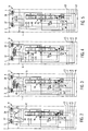
- a multi-line distributor function block 1 includes a three-position directional spool valve W with a feed regulator 13, a tank line 12 to a tank R, a pressure line 11 to a pressure source P, control lines 7, 8 (control pressures Pst) to a control pressure supply 6 in the block 5, and a load pressure signal circuit 14 for a load pressure signal LS.
- the block 2 for example, is placed on top of the block 1, contains in each embodiment of Fig. 1 to 5 in working lines 9, 10 for double-acting or acted upon hydraulic motor M respectively a working flow 2/2-Druckregelsitzventil 3, 4 (a kind of pressure-controlled load-holding valve with leak-free blocking position) for controlling indicated at A, B working currents.
- the block 5 illustrates a possible design of a control pressure supply 6, in which from the pressure line 11 via a pressure reducing valve, a substantially constant pressure level in the control lines 7, 8 (control pressure Pst) is adjustable.
- the control pressure supply 6 could alternatively have its own pressure source, or draw pressure from elsewhere.
- a control pressure of about 30-40 bar is generated via the control pressure supply 6 from a working pressure of up to 300 bar, which serves primarily to actuate the three-position directional spool valve W proportionally.
- the three-position directional spool valve W is formed with a neutral position O, in which both working lines 9, 10 are connected to each other and to the tank line 12, wherein in the neutral position O and the load pressure signal circuit 14 may be relieved to the tank line 12.
- the neutral position O is set, for example via a spring assembly 17 which engages a spool, not shown.
- the three-position directional spool valve W has two proportional pressure controls 15, 16, each with a proportional solenoid 18, 20 and, for example, a pressure reducing valve 19, 21, and a tap 22, 23 per proportional pressure pilot 15, 16, at which the actual of the Proportional pressure pilot control 15, 16 for the spool piston Actuating pressure (Pst1, Pst2) via one of two control lines 24, 25 in the block 2 is transferable.
- each working flow 2/2 pressure regulating seat valve 3, 4 has a blocking direction pressure pilot 26 with a pilot line branching from a working line 9, 10 and an opening direction pressure pilot 27, 28 (acting against a control spring).
- Opening direction Druckvortician 27, 28 extends a short-circuit line 29, in which two opposing check valves 30 are arranged, each of which locks in the direction of a connected therebetween branch line 31 leading to the control line 24 and includes a pilot operated check valve 32.
- An unlock line 33 of the check valve 32 is connected to the other control line 25.
- the embodiment of the electro-hydraulic control devices in Fig. 2 is different from that of Fig. 1 by a different equipment of the block 2.
- the two control lines 24, 25 of the taps 22, 23 each connected to a shuttle valve 34, 35.
- Each shuttle valve 34, 35 is centrally connected to an opening direction pressure pilot 27, 28 of the two working current 2/2 Druckregelsitzventile 3, 4.
- the embodiment of the electro-hydraulic control device in Fig. 3 is different from those of Fig. 1 and 2 by other features of the blocks 1, 2.
- block 2 is the opening direction pressure pilot controls 27, 28 of the two working flow 2/2 Druckregelsitzventile 3, 4 together assigned a 3/4 pressure control valve 42, the two sides of the control lines 24, 25th is pressure-controlled.
- the opening direction pressure pilot controls 27, 28 are connected to each other and to an output of a black / white solenoid switching valve 40 included in an auxiliary control line 38.
- the auxiliary control line 38 leads, for example, to a control line 8 in block 1 and is thus connected to the control pressure supply 6.
- a connection connected to a tank line 41 is blocked in the 3/4-pressure control valve.
- a second input of the black / white magnetic switching valve 40 is also connected to the tank line 41.
- the tank line 41 and the auxiliary control line 38 is provided.
- the black / white solenoid switching valve has two inputs connected to the auxiliary control line 38 and the tank line 41.
- the embodiment of the electro-hydraulic control device H in Fig. 4 is the of Fig. 3 Similarly, that is, the block 2 includes a two pilot control lines 24, 25 each pressure-controlled 3/4-pressure control valve 43 which is formed with a center position in which a connection to the tank line 41 via a throttle 44 is continuous. To another port of the 3/4-pressure control valve, a branch line 45 is connected, which branches off from the control line 25 and contains the pilot-operated check valve 32, the unlock line 46 is connected to the control line 24.
- the embodiment of the electro-hydraulic control device H in Fig. 5 is the of Fig. 1 similar.
- an auxiliary control line 48 is provided, which branches off via a shuttle valve 47 from the load pressure signal circuit 14 and leads to a shuttle valve 49 in the block 2, which is arranged in the short-circuit line 29 between the two opening direction Druckvortician 27, 28.
- the load pressure signal circuit 14 is relieved via a throttle 50 in the neutral position O of the three-position directional spool valve W to the tank line 12.
- both proportional pressure pilot controls 15, 16 are de-energized and the neutral position O is set.
- the load of the hydraulic motor M is held by the blocking working flow 2/2-Druckregelsitz valves 3, 4, since the control lines 24, 25 are depressurized.
- the proportional magnet 18 is energized (PE01), so that the second position b is set, which connects the pressure line 11 with the working line 9.
- the working line 10 is then connected to the tank R.
- the actual control pressure Pst1 which transmits the control line 24 to the opening direction pressure pilot 27 of the working flow 2/2-Druckregelsitzventils 3 so that it assumes a proportional open position.
- the opening direction pressure pilot control 28 of the other working flow 2/2 pressure regulating seat valve 4 is isolated via the left check valve 30. Also, the check valve 32 holds its blocking position, since in the Entsperr Arthur 33 and the control line 25 no control pressure is applied.
- the proportional solenoid 20 is energized to adjust the first position a, in which the pressure line 11 is connected to the working line 10, whereas the working line 9 with the Tank R.
- the actual control pressure Pst2 tapped in the control line 25 via the tap 23 is transmitted to the opening direction pressure pilot control 28 of the working flow 2/2 pressure regulating seat valve 4, which is proportionally turned on.
- the check valve 32 is unlocked via the unlock line 33.
- the opening direction pressure pilot 27 remains over the in Fig. 1 right non-return valve 30 isolated.
- both proportional solenoids 18, 20 are energized simultaneously and similarly, so that the three-position directional spool valve W occupies either the neutral position O or is held therein, but in both control lines 24, 25 equal control pressures are fed (Pst1, Pst2) acting on both opening-direction pressure pilot controls 27, 28 and driving both working-current 2/2 pressure-regulating poppet valves so that both sides of the hydraulic motor M are connected to each other and to the tank R.
- Pst1, Pst2 both opening-direction pressure pilot controls 27, 28
- the control pressure Pst1, Pst2 can be proportionally controlled in each control line 24, 25, for example at a control pressure level of about 30-40 bar in the control lines 7, 8 with about 3 bar to 25 bar.
- the energization of the proportional solenoid 18, 20 for adjusting the floating position is the same, but can be individually stronger or weaker to make the switching of the working flow 2/2-Druckregelsitzventile 3, 4 harder or softer as desired.
- control pressures Pst1 and Pst2 in the control lines 24, 25 from the taps 22, 23 are also used for pressure precontrol of the 3/4 pressure control valve 42.
- the control pressure Pst2 In the position a with energization of the proportional solenoid 20 of the three-position directional spool valve W is in the control line 25, the control pressure Pst2, so that the 3/4 pressure control valve 42 is brought into a position in which the opening direction pressure pilot control 28 is applied to the control pressure Pst2 is and alsêtt the working flow 2/2-Druckregelsitzventil 4, so that via the working line 10 hydraulic medium is fed into the hydraulic motor M.
- both proportional solenoids 18, 20 are energized similarly, so that the control pressures Pst1 and Pst2 hold the 3/4 pressure control valve 42 in the middle position shown, in which case first the opening direction pressure pilot controls 27, 28 via the Black / white magnetic switching valve 39 (black / white magnet 40 without current) to the tank line 41 are relieved.
- the floating position can be adjusted without energization of the two proportional solenoids 18, 20 only via the operation of the black / white magnetic switching valve 39 from the control pressure supply 6, since the 3/4 pressure control valve 42 at unpressurized control lines 24, 25 by springs in the middle position is held.
- the actuation of the opening direction pressure pilot controls 27, 28 via the proportional solenoids 18, 20 or 18 or 20 may be proportionally controlled using the pressure regulating function of the 3/4 pressure control valve 42, that is, for example between sharp and mild.
- a 3/4 pressure control valve 43 is provided with spring-centered position, in the middle position both opening direction pressure pilot controls 27, 28 are connected to each other and via a throttle 44 to the tank line 41 and thus relieved.
- the pilot-operated check valve 32 is in the blocking position, so then possibly in the control line 25 adjacent control pressure Pst2 is not transmitted to the left port of the 3/4 pressure control valve 43, but the 3/4 Pressure control valve 43 is proportionally set to a position in which the control line 25 is connected to the opening direction pressure pilot control 28 of the working flow 2/2-Druckregelsitzventils 4 and auf Strukturt this.
- the opening direction pressure pilot 27 is further depressurized, so that the working flow 2/2-Druckregelsitzventil 3 keeps its blocking position.
- the reverse control function results when only the control line 24 contains control pressure Pst1, although then the check valve 32 is unlocked via the unlock line 46. Only the left working flow 2/2 pressure regulating seat valve 3 is opened proportionally.
- both proportional solenoids 18, 20 are energized in a similar manner, so that control voltages Pst1 and Pst2 are present in both control lines 24, 25 and the check valve 32 is opened.
- the 3/4 pressure control valve 43 retains its center position shown.
- Both opening direction pressure pilot controls 27, 28 are acted upon by the control pressure Pst2, so that both working flow 2/2-Druckregelsitz valves 3, 4 are controlled proportionally.
- the pilot-operated check valve 32 is suitably provided with an unlock-pre-discharge function (not shown) to achieve a favorable duty ratio, for example, up to 1:30 or less (for example, between the release pressure and the lock pressure).
Landscapes
- Engineering & Computer Science (AREA)
- Physics & Mathematics (AREA)
- Fluid Mechanics (AREA)
- Mechanical Engineering (AREA)
- General Engineering & Computer Science (AREA)
- Fluid-Pressure Circuits (AREA)
Abstract
Description
Die Erfindung betrifft eine elektrohydraulische Steuervorrichtung der im Oberbegriff des Patentanspruchs Nr. 1 angegebenen Art.The invention relates to an electro-hydraulic control device specified in the preamble of claim no. 1 Art.
Bei aus
Der Erfindung liegt die Aufgabe zugrunde, eine elektrohydraulische Steuervorrichtung der eingangs genannten Art anzugeben, die baulich einfacher, schnell ansprechend und universell für unterschiedliche Steueraufgaben von doppeltwirkenden Hydromotoren geeignet ist.The invention has for its object to provide an electro-hydraulic control device of the type mentioned, which is structurally simple, quick response and universally suitable for different control tasks of double-acting hydraulic motors.
Die gestellte Aufgabe wird mit den Merkmalen des Patentanspruchs 1 gelöst.The stated object is achieved with the features of claim 1.
Da erfindungsgemäß die Schwimmstellung in der Neutralstellung durch gleichzeitiges Bestromen beider Proportional-Druckvorsteuerungen einstellbar ist, genügt ein kostengünstiges und schnell ansprechendes Dreistellungs-Schieberventil mit zum Tank offener Neutralstellung, um dennoch alle erforderlichen Steuerfunktionen durchführen zu können.Since, according to the invention, the floating position in the neutral position is adjustable by simultaneously energizing both proportional pressure pilot controls, a cost-effective and quickly responding three-position slide valve with a neutral position open to the tank is sufficient in order nevertheless to be able to perform all required control functions.
Die gleichzeitige Bestromung, zweckmäßig mit gleichem Stromwert, beider Proportional-Druckvorsteuerungen ist steuerungsseitig einfach beherrschbar, um ohne vierte Stellung des Dreistellungs-Wegeschieberventils die Schwimmstellung einstellen zu können.The simultaneous energization, expedient with the same current value, both proportional pressure pilot controls is easy to control on the control side to be able to adjust the floating position without fourth position of the three-position directional spool valve.
Bei einer zweckmäßigen Ausführungsform ist zusätzlich im Steuerkreis der beiden Arbeitsstrom-2/2-Druckregelsitzventile ein Schwarz/Weiß-Magnetschaltventil vorgesehen, über das die Schwimmstellung indirekt mit zweifach aufgebrachtem Steuerdruck aus der Steuerdruckversorgung einstellbar ist. Die gleichzeitige Bestromung beider Proportional-Druckvorsteuerungen und des Magnetschaltventils steuert für die Schwimmstellung beide Arbeitsstrom-2/2-Druckregelsitzventile auf und verbindet somit beide Arbeitsleitungen mit dem Tank.In an expedient embodiment, a black / white magnetic switching valve is additionally provided in the control circuit of the two working
Bei einer zweckmäßigen Ausführungsform ist jede von zwei zum Steuerkreis der beiden Arbeitsstrom-2/2-Druckregelsitzventile gehörende Steuerleitung an eine am Dreistellungs-Wegeschieberventil vorgesehene Anzapfung einer Proportional-Druckvorsteuerung angeschlossen. Über die Anzapfung kann der von der Proportional-Druckvorsteuerung aus dem Druckniveau der Steuerdruckversorgung abgeleitete tatsächliche Steuerdruck zum individuellen Betätigen der Arbeitsstrom-2/2-Druckregelsitzventile eingesetzt werden, und auch zur Einstellung der Schwimmstellung.In an expedient embodiment, each of two belonging to the control circuit of the two working
Das Dreistellungs-Wegeschieberventil ist von auf anderen Gebieten der Technik, zum Beispiel Kranhydraulik und dergleichen, üblicher Ausbildung, beispielweise der Typ PSL (für eine Konstantpumpe als Druckquelle) oder PSV (für eine Regelpumpe als Druckquelle) der Anmelderin. Die einzige Modifikation gegenüber den gängigen Typen besteht darin, jeweils eine Anzapfung zu einem Kanal oder einer Steuerkammer vorzusehen, in welchem bzw. welcher ein von einem Proportionalmagneten betätigtes Druckminderventil den tatsächlichen Schieber-Betätigungsdruck aus dem Druckniveau der Steuerdruckversorgung proportional generiert. Auf diese Weise ist eine proportionale Betätigung der Arbeitsstrom-2/2-Druckregelsitzventile allein über die Proportionalmagneten der Proportional-Druckvorsteuerungen des Dreistellungs-Wegeschieberventils möglich, was besonders günstig ist, wenn die elektrohydraulische Steuervorrichtung beispielsweise in ein CAN-Bussystem eingegliedert ist. Die Modifikation der gängigen Typen der Dreistelllungs-Wegeschieberventile ist baulich einfach. Die Anzapfungen können, falls nicht benötigt, durch Stopfen verschlossen werden.The three-position directional spool valve is of conventional design, for example, type PSL (for a constant-pressure pump as a pressure source) or PSV (for a control pump as a pressure source) of the applicant in other fields of technology, for example crane hydraulics and the like. The only modification to the common types is to provide a tap each to a channel or control chamber in which a pressure-reducing valve actuated by a proportional solenoid proportionally generates the actual slide actuating pressure from the pressure level of the control pressure supply. In this way, a proportional actuation of the working
Zweckmäßig wird somit zum direkten Einstellen der Schwimmstellung mittels der Steuerdrücke von beiden gleichzeitig bestromten Proportional-Druckvorsteuerungen jede Steuerleitung von der Anzapfung direkt an die Öffnungsrichtungs-Druckvorsteuerung eines Arbeitsstrom-2/2-Druckregelsitzventils angeschlossen.Appropriately, therefore, for direct adjustment of the floating position by means of the control pressures of both simultaneously energized proportional pressure pilot controls each control line from the tap directly connected to the opening direction pressure pilot control of a working
Bei einer weiteren Ausführungsform ist zwischen beiden Steuerleitungen eine Kurzschlussleitung mit zwei gegensinnigen Rückschlagventilen vorgesehen, von der zwischen den Rückschlagventilen zu einer der Steuerleitungen eine Zweigleitung abzweigt, die ein hydraulisch entsperrbares Rückschlagventil enthält. Die Entsperrleitung des Rückschlagventils wird dann an die andere Steuerleitung angeschlossen. Auf diese Weise lässt sich sicher stellen, dass die beiden Öffnungsrichtungs-Druckvorsteuerungen der Arbeitsstrom-2/2-Druckregelsitzventile zum Einstellen zumindest der Schwimmstellung exakt gleich druckbeaufschlagt werden.In another embodiment, a short-circuit line with two opposing check valves is provided between the two control lines, branches off from the between the check valves to one of the control lines, a branch line containing a hydraulically releasable check valve. The unlock line of the check valve is then connected to the other control line. In this way it can be ensured that the two opening direction Druckvorsteuerungen the working
Bei einer weiteren Ausführungsform enthält eine jede der zur Öffnungsrichtungs-Druckvorsteuerung ein Arbeitsstrom-2/2-Druckregelsitzventils führende Steuerleitung ein Wechselventil. Von jedem Wechselventil führt eine Hilfssteuerleitung zu derjenigen Arbeitsleitung, in der das andere Arbeitstrom-2/2-Druckregelsitzventil angeordnet ist, sodass beispielsweise die beiden Arbeitsstrom-2/2-Druckregelsitzventile für die Einstellung der Schwimmstellung an ihren Sperrrichtungs-Druckvorsteuerungen überkreuz druckentlastbar und/oder auch steuerbar sind.In another embodiment, each of the control line leading to the opening direction pressure pilot control of a normally-open 2/2 pressure control poppet valve includes a shuttle valve. From each shuttle valve performs an auxiliary control line to that working line in which the other working current 2/2-Druckregelsitzventil is arranged so that, for example, the two working
Bei einer weiteren zweckmäßigen Ausführungsform mit dem den beiden Arbeitstrom-2/2-Druckregelsitzventilen gemeinsamen Schwarz/Weiß-Magnetschaltventil ist zwischen den beiden, in der Schwimmstellung mit Steuerdruck aus der Steuerdruckversorgung beaufschlagbaren Arbeitsstrom-2/2-Druckregelsitzventilen ein mit einem Anschluss mit dem Schwarz/Weiß-Magnetschaltventil und mit einem anderen Anschluss mit dem Tank verbundenes, druckvorgesteuertes 3/4-Druckregelventil vorgesehen. Dieses Druckregelventil weist eine Mittelstellung auf, in der es zum Tank absperrt und Steuerleitungszweige zu den Arbeitstrom-2/2-Druckregelsitzventilen verbindet.In a further expedient embodiment with the two working current 2/2 pressure regulating seat valves common black / white magnetic switching valve is between the two acted upon in the floating position with control pressure from the control pressure supply working current 2/2-Druckregelsitzventilen one with a connection with the black / White solenoid valve and with another connection connected to the tank, pressure-controlled 3/4-pressure control valve provided. This pressure control valve has a central position in which it shuts off the tank and connects control line branches to the working
Bei einer weiteren Ausführungsvariante ohne gemeinsames Schwarz/Weiß-Magnetschaltventil ist zwischen den beiden, bei eingestellter Schwimmstellung mit Steuerdruck aus einer der Anzapfungen beaufschlagten Arbeitstrom-2/2-Druckregelsitzventilen ein über ein hydraulisch entsperrbares Rückschlagventil mit der einen Anzapfung und mit einem weiteren Anschluss mit dem Tank verbundenes, druckvorgesteuertes 3/4-Druckregelventil vorgesehen. Dieses Druckregelventil weist eine Mittelstellung auf, in welcher Steuerleitungszweige zu den beiden Arbeitsstrom-2/2-Druckregelsitzventilen miteinander und über eine Drossel auch mit dem Tank verbunden sind. Die Entsperrleitung des Rückschlagventils ist an die jeweils andere Steuerleitung angeschlossen, um das Rückschlagventil mit an der anderen Anzapfung abgegriffenem Steuerdruck zu entsperren.In a further embodiment without common black / white solenoid valve is between the two, with adjusted floating position with control pressure from one of the taps acted upon working current 2/2-Druckregelsitzventilen a via a hydraulic pilot-operated check valve with a tap and with a further connection to the tank connected, pressure-controlled 3/4-pressure control valve provided. This pressure control valve has a central position, in which control line branches are connected to the two working
Bei einer weiteren zweckmäßigen Ausführungsform ist zwischen den beiden Arbeitstrom-2/2-Druckregelsitzventilen eine Kurzschlussverbindung mit einem Wechselventil vorgesehen. Das Wechselventil ist mittig an einen Lastdrucksignalkreis angeschlossen, der in der Neutralstellung des Dreistellungs-Wegeschieberventils über eine Drossel zum Tank entlastet ist, sodass die Öffnungsrichtungs-Druckvorsteuerungen, falls nicht durch gleichzeitige Bestromung beider Proportional-Druckvorsteuerungen die Schwimmstellung eingestellt ist, über den Lastdrucksignalkreis zum Tank entlastet werden.In a further expedient embodiment, a short-circuit connection with a shuttle valve is provided between the two working current 2/2-Druckregelsitzventilen. The shuttle valve is centrally connected to a load pressure signal circuit, which is relieved in the neutral position of the three-position directional spool valve via a throttle to the tank so that the opening direction Druckvorsteuerungen, if not by simultaneous energization of both proportional pressure pilot controls the float position is set via the load pressure signal circuit to the tank be relieved.
Anhand der Zeichnung werden Ausführungsformen des Erfindungsgegenstandes erläutert. Es zeigen:
- Fig. 1
- ein Blockschaltbild einer ersten Ausführungsform einer elektrohydraulischen Steuervorrichtung für einen doppeltwirkenden Hydromotor,
- Fig. 2
- ein Blockschaltbild einer weiteren Ausführungsform,
- Fig. 3
- ein Blockschaltbild einer weiteren Ausführungsform,
- Fig. 4
- ein Blockschaltbild einer weiteren Ausführungsform, und
- Fig. 5
- ein Blockschaltbild einer weiteren Ausführungsform.
- Fig. 1
- 1 is a block diagram of a first embodiment of an electro-hydraulic control device for a double-acting hydraulic motor,
- Fig. 2
- a block diagram of another embodiment,
- Fig. 3
- a block diagram of another embodiment,
- Fig. 4
- a block diagram of another embodiment, and
- Fig. 5
- a block diagram of another embodiment.
Die nachfolgend erläuterten elektrohydraulischen Steuervorrichtungen sind beispielsweise für Arbeitsmaschinen, Landmaschinen oder dergleichen verwendbar, die mit hydraulisch betätigten Werkzeugen, einem Hubwerk und/oder einer hydropneumatischen Achsfederung ausgestatten seien können, und bei denen eine Schwimmstellung des Hydromotors benötigt wird, in welcher der Hydromotor passiv und mit dem Tank verbunden ist.The electrohydraulic control devices explained below can be used, for example, for working machines, agricultural machines or the like, which can be equipped with hydraulically operated tools, a hoist and / or a hydro-pneumatic axle suspension, and in which a floating position of the hydraulic motor is required, in which the hydraulic motor is passive and with connected to the tank.
Die in den
In der Ausführungsform in
Der Block 2, der z.B. oben auf den Block 1 aufgesetzt ist, enthält in jeder Ausführungsform der
Der Block 5 verdeutlicht eine mögliche Bauweise einer Steuerdruckversorgung 6, bei der aus der Druckleitung 11 über ein Druckreduzierventil ein weitgehend konstantes Druckniveau in den Steuerleitungen 7, 8 (Steuerdruck Pst) einstellbar ist. Die Steuerdruckversorgung 6 könnte alternativ eine eigene Druckquelle aufweisen, oder Druck von anderer Stelle beziehen. Beispielweise wird über die Steuerdruckversorgung 6 aus einem Arbeitsdruck von bis zu 300 bar ein Steuerdruck von etwa 30 ― 40 bar erzeugt, der primär dazu dient, dass Dreistellungs-Wegeschieberventil W proportional zu betätigen.The block 5 illustrates a possible design of a
Das Dreistellungs-Wegeschieberventil W ist mit einer Neutralstellung O ausgebildet, in der beide Arbeitsleitungen 9, 10 miteinander und mit der Tankleitung 12 verbunden sind, wobei in der Neutralstellung O auch der Lastdrucksignalkreis 14 zur Tankleitung 12 entlastet sein kann. Die Neutralstellung O wird beispielweise über eine Federanordnung 17 eingestellt, die an einem nicht gezeigten Schieberkolben angreift. Das Dreistellungs-Wegeschieberventil W weist zwei Proportional-Drucksteuerungen 15, 16, jeweils mit einem Proportionalmagneten 18, 20 und beispielsweise einem Druckminderventil 19, 21 auf, sowie eine Anzapfung 22, 23 pro Proportional-Druckvorsteuerung 15, 16, an der der tatsächlich von der Proportional-Druckvorsteuerung 15, 16 für den Schieberkolben eingesteuerte Betätigungsdruck (Pst1, Pst2) über je eine von zwei Steuerleitungen 24, 25 in den Block 2 übertragbar ist.The three-position directional spool valve W is formed with a neutral position O, in which both working
Im Block 2 weist jedes Arbeitsstrom-2/2-Druckregelsitzventil 3, 4 eine Sperrrichtungs-Druckvorsteuerung 26 mit einer von einer Arbeitsleitung 9, 10 abzweigenden Vorsteuerleitung sowie eine Öffnungsrichtungs-Druckvorsteuerung 27, 28 (gegen eine Regelfeder wirkend) auf. Zwischen Öffnungsrichtungs-Druckvorsteuerungen 27, 28 verläuft eine Kurzschlussleitung 29, in der zwei gegensinnige Rückschlagventile 30 angeordnet sind, deren jedes in Richtung zu einer dazwischen angeschlossenen Zweigleitung 31 sperrt, die zu der Steuerleitung 24 führt und ein entsperrbares Rückschlagventil 32 enthält. Eine Entsperrleitung 33 des Rückschlagventils 32 ist an die andere Steuerleitung 25 angeschlossen.In
Die Ausführungsform der elektrohydraulischen Steuervorrichtungen in
Die Ausführungsform der elektrohydraulischen Steuervorrichtung in
Die Ausführungsform der elektrohydraulischen Steuervorrichtung H in
Die Ausführungsform der elektrohydraulischen Steuervorrichtung H in
In der in
Um über die Arbeitsleitung 10 Hydraulikmedium in den Hydromotor M einzuspeisen, wird, ausgehend von der Neutralstellung O, der Proportionalmagnet 20 bestromt, um die erste Stellung a einzustellen, in der die Druckleitung 11 mit der Arbeitsleitung 10 verbunden ist, hingegen die Arbeitsleitung 9 mit dem Tank R. Der in der Steuerleitung 25 über die Anzapfung 23 abgegriffene, tatsächliche Steuerdruck Pst2 wird an die Öffnungsrichtungs-Druckvorsteuerung 28 des Arbeitsstrom-2/2-Druckregelsitzventils 4 übertragen, das proportional aufgesteuert wird. Über die Entsperrleitung 33 wird zwar das Rückschlagventil 32 entsperrt. Da jedoch die Steuerleitung 24 keinen Steuerdruck enthält, bleibt die Öffnungsrichtungs-Druckvorsteuerung 27 über das in
Um die Schwimmstellung des Hydromotors M einzustellen, werden beide Proportionalmagneten 18, 20 gleichzeitig und gleichartig bestromt, sodass das Dreistellungs-Wegeschieberventil W entweder die Neutralstellung O einnimmt oder in dieser gehalten wird, jedoch in beiden Steuerleitungen 24, 25 gleiche Steuerdrücke eingespeist werden (Pst1, Pst2), die an beiden Öffnungsrichtungs-Druckvorsteuerungen 27, 28 wirken und beide Arbeitsstrom-2/2-Druckregelsitzventile aufsteuern, sodass beide Seiten des Hydromotors M miteinander und mit dem Tank R verbunden sind. Über die Entsperrleitung 33 wird auch das Rückschlagventil 23 entsperrt, so dass sich zusätzlich der Steuerdruck in der Steuerleitung 24 über die beiden dann öffnenden Rückschlagventile 30 aus der Zweigleitung 31 gleichmäßig verteilt.In order to adjust the floating position of the hydraulic motor M, both
Der Steuerdruck Pst1, Pst2 kann in jeder Steuerleitung 24, 25 proportional eingesteuert werden, beispielsweise bei einem Steuerdruckniveau von etwa 30 ― 40 bar in den Steuerleitungen 7, 8 mit etwa 3 bar bis 25 bar. Die Bestromung der Proportionalmagneten, 18, 20 zum Einstellen der Schwimmstellung ist zwar gleich, kann aber individuell stärker oder schwächer gewählt werden, um die Umschaltung der Arbeitsstrom-2/2-Druckregelsitzventile 3, 4 nach Wunsch härter oder weicher vorzunehmen.The control pressure Pst1, Pst2 can be proportionally controlled in each
Bei der Ausführungsform in
In der Ausführungsform in
Um die Schwimmstellung für den Hydromotor M einzustellen, werden beide Proportionalmagneten 18, 20 gleichartig bestromt, so dass die Steuerdrücke Pst1 und Pst2 das 3/4-Druckregelventil 42 in der gezeigten Mittelstellung halten, wobei hier zunächst die Öffnungsrichtungs-Druckvorsteuerungen 27, 28 über das Schwarz/Weiß-Magnetschaltventil 39 (Schwarz/Weiß-Magnet 40 unbestromt) zur Tankleitung 41 entlastet sind. Erst wenn der Schwarz/Weiß-Magnet 40 bestromt wird und das Magnetschaltventil 39 in die andere Stellung umschaltet, wird die Verbindung zur Tankleitung 41 blockiert und wird gleichzeitig die Steuerleitung 38 über den linken Eingang des Magnetschaltventils 39 mit beiden Öffnungsrichtungs-Druckvorsteuerungen 27, 28 verbunden, so dass beide Arbeitsstrom-2/2-Druckregelsitzventile 3, 4 mittels des Steuerdrucks Pst der Steuerdruckversorgung 6 aufgesteuert werden und beide Arbeitsleitungen 9, 10 im Dreistellungs-Wegeschieberventil W miteinander und mit dem Tank R verbunden sind (Schwimmstellung). Bei dieser Ausführungsform kann ferner die Schwimmstellung ohne Bestromung der beiden Proportionalmagneten 18, 20 nur über die Betätigung des Schwarz/Weiß-Magnetschaltventils 39 aus der Steuerdruckversorgung 6 eingestellt werden, da das 3/4-Druckregelventil 42 bei drucklosen Steuerleitungen 24, 25 durch Federn in der Mittelstellung gehalten ist. Ferner lässt sich die Beaufschlagung der Öffnungsrichtungs-Druckvorsteuerungen 27, 28 über die Proportionalmagneten 18, 20 oder 18 oder 20 unter Nutzen der Druckregelfunktion des 3/4-Druckregelventils 42 proportional steuern, das heißt, zum Beispiel zwischen scharf und mild variieren.In order to adjust the floating position for the hydraulic motor M, both
In der Ausführungsform der elektrohydraulischen Steuervorrichtung H in
In der Ausführungsform in
In den Ausführungsformen der
Claims (10)
Priority Applications (1)
| Application Number | Priority Date | Filing Date | Title |
|---|---|---|---|
| EP20100195694 EP2466153B1 (en) | 2010-12-17 | 2010-12-17 | Electrohydraulic control device |
Applications Claiming Priority (1)
| Application Number | Priority Date | Filing Date | Title |
|---|---|---|---|
| EP20100195694 EP2466153B1 (en) | 2010-12-17 | 2010-12-17 | Electrohydraulic control device |
Publications (2)
| Publication Number | Publication Date |
|---|---|
| EP2466153A1 true EP2466153A1 (en) | 2012-06-20 |
| EP2466153B1 EP2466153B1 (en) | 2013-08-14 |
Family
ID=43902983
Family Applications (1)
| Application Number | Title | Priority Date | Filing Date |
|---|---|---|---|
| EP20100195694 Not-in-force EP2466153B1 (en) | 2010-12-17 | 2010-12-17 | Electrohydraulic control device |
Country Status (1)
| Country | Link |
|---|---|
| EP (1) | EP2466153B1 (en) |
Cited By (3)
| Publication number | Priority date | Publication date | Assignee | Title |
|---|---|---|---|---|
| EP2696080A1 (en) | 2012-08-09 | 2014-02-12 | HAWE Hydraulik SE | Commande électro-hydraulique |
| EP2799722A1 (en) | 2013-05-03 | 2014-11-05 | HAWE Hydraulik SE | Hydraulic control device and logic element |
| US10900562B2 (en) * | 2015-12-07 | 2021-01-26 | Kubota Corporation | Hydraulic system of work machine and work machine |
Citations (6)
| Publication number | Priority date | Publication date | Assignee | Title |
|---|---|---|---|---|
| EP1281872A1 (en) | 2001-08-04 | 2003-02-05 | Robert Bosch Gmbh | Electrohydraulic device for controlling a bouble acting engine |
| DE10340506A1 (en) * | 2003-09-03 | 2005-04-07 | Sauer-Danfoss Aps | Valve arrangement and hydraulic drive |
| DE102005005314A1 (en) | 2004-12-20 | 2006-06-22 | Bosch Rexroth Aktiengesellschaft | Valve arrangement and method for controlling a double-acting consumer |
| WO2007019712A1 (en) * | 2005-08-19 | 2007-02-22 | Bucher Hydraulics Ag | Circuit for controlling a double-action hydraulic drive cylinder |
| EP2031256A2 (en) | 2007-08-29 | 2009-03-04 | Robert Bosch GmbH | Lifting device and method for operating a lifting device |
| EP2071195A2 (en) * | 2007-12-10 | 2009-06-17 | Volvo Construction Equipment Holding Sweden AB | Hydraulic circuit with load holding valves operated by external pilot pressure |
-
2010
- 2010-12-17 EP EP20100195694 patent/EP2466153B1/en not_active Not-in-force
Patent Citations (6)
| Publication number | Priority date | Publication date | Assignee | Title |
|---|---|---|---|---|
| EP1281872A1 (en) | 2001-08-04 | 2003-02-05 | Robert Bosch Gmbh | Electrohydraulic device for controlling a bouble acting engine |
| DE10340506A1 (en) * | 2003-09-03 | 2005-04-07 | Sauer-Danfoss Aps | Valve arrangement and hydraulic drive |
| DE102005005314A1 (en) | 2004-12-20 | 2006-06-22 | Bosch Rexroth Aktiengesellschaft | Valve arrangement and method for controlling a double-acting consumer |
| WO2007019712A1 (en) * | 2005-08-19 | 2007-02-22 | Bucher Hydraulics Ag | Circuit for controlling a double-action hydraulic drive cylinder |
| EP2031256A2 (en) | 2007-08-29 | 2009-03-04 | Robert Bosch GmbH | Lifting device and method for operating a lifting device |
| EP2071195A2 (en) * | 2007-12-10 | 2009-06-17 | Volvo Construction Equipment Holding Sweden AB | Hydraulic circuit with load holding valves operated by external pilot pressure |
Cited By (4)
| Publication number | Priority date | Publication date | Assignee | Title |
|---|---|---|---|---|
| EP2696080A1 (en) | 2012-08-09 | 2014-02-12 | HAWE Hydraulik SE | Commande électro-hydraulique |
| EP2799722A1 (en) | 2013-05-03 | 2014-11-05 | HAWE Hydraulik SE | Hydraulic control device and logic element |
| US10900562B2 (en) * | 2015-12-07 | 2021-01-26 | Kubota Corporation | Hydraulic system of work machine and work machine |
| US11644098B2 (en) | 2015-12-07 | 2023-05-09 | Kubota Corporation | Hydraulic system of work machine and work machine |
Also Published As
| Publication number | Publication date |
|---|---|
| EP2466153B1 (en) | 2013-08-14 |
Similar Documents
| Publication | Publication Date | Title |
|---|---|---|
| DE102004050294B3 (en) | Hydraulic valve arrangement | |
| EP1915538B1 (en) | Circuit for controlling a double-action hydraulic drive cylinder | |
| DE102006003414B3 (en) | Hydraulic circuit arrangement | |
| DE10138389A1 (en) | Electro-hydraulic device for controlling a double-acting motor | |
| EP3759357A1 (en) | Valve arrangement for supplying a hydraulic consumer with pressure medium | |
| EP3018364B1 (en) | Control device with sliding piston | |
| EP3584450B1 (en) | Agricultural or civil engineering working machine with a load signal control system of a hydraulic system of an attachment | |
| EP2320094A2 (en) | Valve assembly | |
| EP2466153B1 (en) | Electrohydraulic control device | |
| EP2268927A1 (en) | Control arrangement for controlling a control valve | |
| DE102004025322A1 (en) | Hydraulic valve arrangement | |
| EP0115590A2 (en) | Hydraulic control device | |
| DE19548943B4 (en) | valve assembly | |
| EP2157319B1 (en) | Hydraulic device for a hydro motor | |
| EP2466154B1 (en) | Electrohydraulic control device | |
| EP0823559B1 (en) | Hydraulic control device | |
| EP2597209B1 (en) | Electronic-hydraulic hoisting gear regulation system | |
| EP3135924B1 (en) | Hydraulic device | |
| EP3398418A1 (en) | Hydraulic system of a machine usable in agriculture or civil engineering | |
| EP2896839B1 (en) | Device for locking and pressure adjustment | |
| AT396618B (en) | HYDRAULIC THREE-WAY CONTINUOUS VALVE FOR BLOCK INSTALLATION | |
| DE4418881A1 (en) | Electrohydraulic control system and control valve for farm vehicle lifting gear | |
| DE102017102307B3 (en) | Motor vehicle with open passenger compartment | |
| EP2597210B1 (en) | Electrohydraulic control device | |
| EP4130493B1 (en) | Hydraulic control assembly |
Legal Events
| Date | Code | Title | Description |
|---|---|---|---|
| PUAI | Public reference made under article 153(3) epc to a published international application that has entered the european phase |
Free format text: ORIGINAL CODE: 0009012 |
|
| 17P | Request for examination filed |
Effective date: 20110610 |
|
| AK | Designated contracting states |
Kind code of ref document: A1 Designated state(s): AL AT BE BG CH CY CZ DE DK EE ES FI FR GB GR HR HU IE IS IT LI LT LU LV MC MK MT NL NO PL PT RO RS SE SI SK SM TR |
|
| AX | Request for extension of the european patent |
Extension state: BA ME |
|
| 17Q | First examination report despatched |
Effective date: 20120629 |
|
| GRAP | Despatch of communication of intention to grant a patent |
Free format text: ORIGINAL CODE: EPIDOSNIGR1 |
|
| RIN1 | Information on inventor provided before grant (corrected) |
Inventor name: STOENNER, CHRISTOPH Inventor name: MACIT, RECEP Inventor name: HEUSSER, MARTIN |
|
| GRAS | Grant fee paid |
Free format text: ORIGINAL CODE: EPIDOSNIGR3 |
|
| GRAA | (expected) grant |
Free format text: ORIGINAL CODE: 0009210 |
|
| AK | Designated contracting states |
Kind code of ref document: B1 Designated state(s): AL AT BE BG CH CY CZ DE DK EE ES FI FR GB GR HR HU IE IS IT LI LT LU LV MC MK MT NL NO PL PT RO RS SE SI SK SM TR |
|
| REG | Reference to a national code |
Ref country code: GB Ref legal event code: FG4D Free format text: NOT ENGLISH |
|
| REG | Reference to a national code |
Ref country code: AT Ref legal event code: REF Ref document number: 627029 Country of ref document: AT Kind code of ref document: T Effective date: 20130815 Ref country code: CH Ref legal event code: EP |
|
| REG | Reference to a national code |
Ref country code: IE Ref legal event code: FG4D Free format text: LANGUAGE OF EP DOCUMENT: GERMAN |
|
| REG | Reference to a national code |
Ref country code: DE Ref legal event code: R096 Ref document number: 502010004347 Country of ref document: DE Effective date: 20131010 |
|
| REG | Reference to a national code |
Ref country code: NL Ref legal event code: VDEP Effective date: 20130814 |
|
| REG | Reference to a national code |
Ref country code: LT Ref legal event code: MG4D |
|
| PG25 | Lapsed in a contracting state [announced via postgrant information from national office to epo] |
Ref country code: SE Free format text: LAPSE BECAUSE OF FAILURE TO SUBMIT A TRANSLATION OF THE DESCRIPTION OR TO PAY THE FEE WITHIN THE PRESCRIBED TIME-LIMIT Effective date: 20130814 Ref country code: CY Free format text: LAPSE BECAUSE OF FAILURE TO SUBMIT A TRANSLATION OF THE DESCRIPTION OR TO PAY THE FEE WITHIN THE PRESCRIBED TIME-LIMIT Effective date: 20130828 Ref country code: HR Free format text: LAPSE BECAUSE OF FAILURE TO SUBMIT A TRANSLATION OF THE DESCRIPTION OR TO PAY THE FEE WITHIN THE PRESCRIBED TIME-LIMIT Effective date: 20130814 Ref country code: NO Free format text: LAPSE BECAUSE OF FAILURE TO SUBMIT A TRANSLATION OF THE DESCRIPTION OR TO PAY THE FEE WITHIN THE PRESCRIBED TIME-LIMIT Effective date: 20131114 Ref country code: IS Free format text: LAPSE BECAUSE OF FAILURE TO SUBMIT A TRANSLATION OF THE DESCRIPTION OR TO PAY THE FEE WITHIN THE PRESCRIBED TIME-LIMIT Effective date: 20131214 Ref country code: LT Free format text: LAPSE BECAUSE OF FAILURE TO SUBMIT A TRANSLATION OF THE DESCRIPTION OR TO PAY THE FEE WITHIN THE PRESCRIBED TIME-LIMIT Effective date: 20130814 Ref country code: PT Free format text: LAPSE BECAUSE OF FAILURE TO SUBMIT A TRANSLATION OF THE DESCRIPTION OR TO PAY THE FEE WITHIN THE PRESCRIBED TIME-LIMIT Effective date: 20131216 |
|
| PG25 | Lapsed in a contracting state [announced via postgrant information from national office to epo] |
Ref country code: LV Free format text: LAPSE BECAUSE OF FAILURE TO SUBMIT A TRANSLATION OF THE DESCRIPTION OR TO PAY THE FEE WITHIN THE PRESCRIBED TIME-LIMIT Effective date: 20130814 Ref country code: FI Free format text: LAPSE BECAUSE OF FAILURE TO SUBMIT A TRANSLATION OF THE DESCRIPTION OR TO PAY THE FEE WITHIN THE PRESCRIBED TIME-LIMIT Effective date: 20130814 Ref country code: SI Free format text: LAPSE BECAUSE OF FAILURE TO SUBMIT A TRANSLATION OF THE DESCRIPTION OR TO PAY THE FEE WITHIN THE PRESCRIBED TIME-LIMIT Effective date: 20130814 Ref country code: PL Free format text: LAPSE BECAUSE OF FAILURE TO SUBMIT A TRANSLATION OF THE DESCRIPTION OR TO PAY THE FEE WITHIN THE PRESCRIBED TIME-LIMIT Effective date: 20130814 Ref country code: GR Free format text: LAPSE BECAUSE OF FAILURE TO SUBMIT A TRANSLATION OF THE DESCRIPTION OR TO PAY THE FEE WITHIN THE PRESCRIBED TIME-LIMIT Effective date: 20131115 |
|
| PG25 | Lapsed in a contracting state [announced via postgrant information from national office to epo] |
Ref country code: CY Free format text: LAPSE BECAUSE OF FAILURE TO SUBMIT A TRANSLATION OF THE DESCRIPTION OR TO PAY THE FEE WITHIN THE PRESCRIBED TIME-LIMIT Effective date: 20130814 |
|
| PG25 | Lapsed in a contracting state [announced via postgrant information from national office to epo] |
Ref country code: EE Free format text: LAPSE BECAUSE OF FAILURE TO SUBMIT A TRANSLATION OF THE DESCRIPTION OR TO PAY THE FEE WITHIN THE PRESCRIBED TIME-LIMIT Effective date: 20130814 Ref country code: RO Free format text: LAPSE BECAUSE OF FAILURE TO SUBMIT A TRANSLATION OF THE DESCRIPTION OR TO PAY THE FEE WITHIN THE PRESCRIBED TIME-LIMIT Effective date: 20130814 Ref country code: DK Free format text: LAPSE BECAUSE OF FAILURE TO SUBMIT A TRANSLATION OF THE DESCRIPTION OR TO PAY THE FEE WITHIN THE PRESCRIBED TIME-LIMIT Effective date: 20130814 Ref country code: NL Free format text: LAPSE BECAUSE OF FAILURE TO SUBMIT A TRANSLATION OF THE DESCRIPTION OR TO PAY THE FEE WITHIN THE PRESCRIBED TIME-LIMIT Effective date: 20130814 Ref country code: SK Free format text: LAPSE BECAUSE OF FAILURE TO SUBMIT A TRANSLATION OF THE DESCRIPTION OR TO PAY THE FEE WITHIN THE PRESCRIBED TIME-LIMIT Effective date: 20130814 Ref country code: CZ Free format text: LAPSE BECAUSE OF FAILURE TO SUBMIT A TRANSLATION OF THE DESCRIPTION OR TO PAY THE FEE WITHIN THE PRESCRIBED TIME-LIMIT Effective date: 20130814 |
|
| PG25 | Lapsed in a contracting state [announced via postgrant information from national office to epo] |
Ref country code: ES Free format text: LAPSE BECAUSE OF FAILURE TO SUBMIT A TRANSLATION OF THE DESCRIPTION OR TO PAY THE FEE WITHIN THE PRESCRIBED TIME-LIMIT Effective date: 20130814 |
|
| PLBE | No opposition filed within time limit |
Free format text: ORIGINAL CODE: 0009261 |
|
| STAA | Information on the status of an ep patent application or granted ep patent |
Free format text: STATUS: NO OPPOSITION FILED WITHIN TIME LIMIT |
|
| BERE | Be: lapsed |
Owner name: HAWE HYDRAULIK SE Effective date: 20131231 |
|
| 26N | No opposition filed |
Effective date: 20140515 |
|
| REG | Reference to a national code |
Ref country code: DE Ref legal event code: R097 Ref document number: 502010004347 Country of ref document: DE Effective date: 20140515 |
|
| PG25 | Lapsed in a contracting state [announced via postgrant information from national office to epo] |
Ref country code: LU Free format text: LAPSE BECAUSE OF FAILURE TO SUBMIT A TRANSLATION OF THE DESCRIPTION OR TO PAY THE FEE WITHIN THE PRESCRIBED TIME-LIMIT Effective date: 20131217 |
|
| REG | Reference to a national code |
Ref country code: IE Ref legal event code: MM4A |
|
| PG25 | Lapsed in a contracting state [announced via postgrant information from national office to epo] |
Ref country code: IE Free format text: LAPSE BECAUSE OF NON-PAYMENT OF DUE FEES Effective date: 20131217 Ref country code: BE Free format text: LAPSE BECAUSE OF NON-PAYMENT OF DUE FEES Effective date: 20131231 |
|
| PG25 | Lapsed in a contracting state [announced via postgrant information from national office to epo] |
Ref country code: MC Free format text: LAPSE BECAUSE OF FAILURE TO SUBMIT A TRANSLATION OF THE DESCRIPTION OR TO PAY THE FEE WITHIN THE PRESCRIBED TIME-LIMIT Effective date: 20130814 |
|
| PG25 | Lapsed in a contracting state [announced via postgrant information from national office to epo] |
Ref country code: SM Free format text: LAPSE BECAUSE OF FAILURE TO SUBMIT A TRANSLATION OF THE DESCRIPTION OR TO PAY THE FEE WITHIN THE PRESCRIBED TIME-LIMIT Effective date: 20130814 |
|
| PG25 | Lapsed in a contracting state [announced via postgrant information from national office to epo] |
Ref country code: TR Free format text: LAPSE BECAUSE OF FAILURE TO SUBMIT A TRANSLATION OF THE DESCRIPTION OR TO PAY THE FEE WITHIN THE PRESCRIBED TIME-LIMIT Effective date: 20130814 |
|
| PG25 | Lapsed in a contracting state [announced via postgrant information from national office to epo] |
Ref country code: MK Free format text: LAPSE BECAUSE OF FAILURE TO SUBMIT A TRANSLATION OF THE DESCRIPTION OR TO PAY THE FEE WITHIN THE PRESCRIBED TIME-LIMIT Effective date: 20130814 Ref country code: BG Free format text: LAPSE BECAUSE OF FAILURE TO SUBMIT A TRANSLATION OF THE DESCRIPTION OR TO PAY THE FEE WITHIN THE PRESCRIBED TIME-LIMIT Effective date: 20130814 Ref country code: RS Free format text: LAPSE BECAUSE OF FAILURE TO SUBMIT A TRANSLATION OF THE DESCRIPTION OR TO PAY THE FEE WITHIN THE PRESCRIBED TIME-LIMIT Effective date: 20131114 Ref country code: HU Free format text: LAPSE BECAUSE OF FAILURE TO SUBMIT A TRANSLATION OF THE DESCRIPTION OR TO PAY THE FEE WITHIN THE PRESCRIBED TIME-LIMIT; INVALID AB INITIO Effective date: 20101217 |
|
| REG | Reference to a national code |
Ref country code: CH Ref legal event code: PL |
|
| GBPC | Gb: european patent ceased through non-payment of renewal fee |
Effective date: 20141217 |
|
| PG25 | Lapsed in a contracting state [announced via postgrant information from national office to epo] |
Ref country code: MT Free format text: LAPSE BECAUSE OF FAILURE TO SUBMIT A TRANSLATION OF THE DESCRIPTION OR TO PAY THE FEE WITHIN THE PRESCRIBED TIME-LIMIT Effective date: 20130814 |
|
| PG25 | Lapsed in a contracting state [announced via postgrant information from national office to epo] |
Ref country code: CH Free format text: LAPSE BECAUSE OF NON-PAYMENT OF DUE FEES Effective date: 20141231 Ref country code: LI Free format text: LAPSE BECAUSE OF NON-PAYMENT OF DUE FEES Effective date: 20141231 Ref country code: GB Free format text: LAPSE BECAUSE OF NON-PAYMENT OF DUE FEES Effective date: 20141217 |
|
| REG | Reference to a national code |
Ref country code: FR Ref legal event code: PLFP Year of fee payment: 6 |
|
| PGFP | Annual fee paid to national office [announced via postgrant information from national office to epo] |
Ref country code: FR Payment date: 20151221 Year of fee payment: 6 |
|
| PGFP | Annual fee paid to national office [announced via postgrant information from national office to epo] |
Ref country code: IT Payment date: 20151230 Year of fee payment: 6 |
|
| REG | Reference to a national code |
Ref country code: DE Ref legal event code: R082 Ref document number: 502010004347 Country of ref document: DE Representative=s name: GROSSE, SCHUMACHER, KNAUER, VON HIRSCHHAUSEN, DE |
|
| REG | Reference to a national code |
Ref country code: AT Ref legal event code: MM01 Ref document number: 627029 Country of ref document: AT Kind code of ref document: T Effective date: 20151217 |
|
| PG25 | Lapsed in a contracting state [announced via postgrant information from national office to epo] |
Ref country code: AT Free format text: LAPSE BECAUSE OF NON-PAYMENT OF DUE FEES Effective date: 20151217 |
|
| REG | Reference to a national code |
Ref country code: FR Ref legal event code: ST Effective date: 20170831 |
|
| PG25 | Lapsed in a contracting state [announced via postgrant information from national office to epo] |
Ref country code: FR Free format text: LAPSE BECAUSE OF NON-PAYMENT OF DUE FEES Effective date: 20170102 Ref country code: IT Free format text: LAPSE BECAUSE OF NON-PAYMENT OF DUE FEES Effective date: 20161217 |
|
| REG | Reference to a national code |
Ref country code: DE Ref legal event code: R082 Ref document number: 502010004347 Country of ref document: DE Representative=s name: GROSSE, SCHUMACHER, KNAUER, VON HIRSCHHAUSEN, DE Ref country code: DE Ref legal event code: R081 Ref document number: 502010004347 Country of ref document: DE Owner name: HAWE HYDRAULIK SE, DE Free format text: FORMER OWNER: HAWE HYDRAULIK SE, 81673 MUENCHEN, DE |
|
| PG25 | Lapsed in a contracting state [announced via postgrant information from national office to epo] |
Ref country code: AL Free format text: LAPSE BECAUSE OF FAILURE TO SUBMIT A TRANSLATION OF THE DESCRIPTION OR TO PAY THE FEE WITHIN THE PRESCRIBED TIME-LIMIT Effective date: 20130814 |
|
| PGFP | Annual fee paid to national office [announced via postgrant information from national office to epo] |
Ref country code: DE Payment date: 20181212 Year of fee payment: 9 |
|
| REG | Reference to a national code |
Ref country code: DE Ref legal event code: R119 Ref document number: 502010004347 Country of ref document: DE |
|
| PG25 | Lapsed in a contracting state [announced via postgrant information from national office to epo] |
Ref country code: DE Free format text: LAPSE BECAUSE OF NON-PAYMENT OF DUE FEES Effective date: 20200701 |
|
| P01 | Opt-out of the competence of the unified patent court (upc) registered |
Effective date: 20230523 |