EP2320094A2 - Valve assembly - Google Patents
Valve assembly Download PDFInfo
- Publication number
- EP2320094A2 EP2320094A2 EP10188785A EP10188785A EP2320094A2 EP 2320094 A2 EP2320094 A2 EP 2320094A2 EP 10188785 A EP10188785 A EP 10188785A EP 10188785 A EP10188785 A EP 10188785A EP 2320094 A2 EP2320094 A2 EP 2320094A2
- Authority
- EP
- European Patent Office
- Prior art keywords
- control
- valve
- pressure
- consumer
- pilot
- Prior art date
- Legal status (The legal status is an assumption and is not a legal conclusion. Google has not performed a legal analysis and makes no representation as to the accuracy of the status listed.)
- Granted
Links
- 238000005086 pumping Methods 0.000 abstract 1
- 239000012530 fluid Substances 0.000 description 16
- 230000011664 signaling Effects 0.000 description 16
- 230000001276 controlling effect Effects 0.000 description 5
- 238000010586 diagram Methods 0.000 description 4
- 239000010720 hydraulic oil Substances 0.000 description 3
- 240000002834 Paulownia tomentosa Species 0.000 description 2
- 235000010678 Paulownia tomentosa Nutrition 0.000 description 2
- 244000007853 Sarothamnus scoparius Species 0.000 description 2
- 230000000903 blocking effect Effects 0.000 description 2
- 238000010276 construction Methods 0.000 description 2
- 239000003921 oil Substances 0.000 description 2
- 230000002411 adverse Effects 0.000 description 1
- 239000003638 chemical reducing agent Substances 0.000 description 1
- 230000000295 complement effect Effects 0.000 description 1
- 230000003247 decreasing effect Effects 0.000 description 1
- 230000008030 elimination Effects 0.000 description 1
- 238000003379 elimination reaction Methods 0.000 description 1
- 210000003746 feather Anatomy 0.000 description 1
- 230000004941 influx Effects 0.000 description 1
- 230000010354 integration Effects 0.000 description 1
- 230000007257 malfunction Effects 0.000 description 1
- 239000013641 positive control Substances 0.000 description 1
- 230000001105 regulatory effect Effects 0.000 description 1
- 238000010408 sweeping Methods 0.000 description 1
- 238000011144 upstream manufacturing Methods 0.000 description 1
Images


Classifications
-
- F—MECHANICAL ENGINEERING; LIGHTING; HEATING; WEAPONS; BLASTING
- F15—FLUID-PRESSURE ACTUATORS; HYDRAULICS OR PNEUMATICS IN GENERAL
- F15B—SYSTEMS ACTING BY MEANS OF FLUIDS IN GENERAL; FLUID-PRESSURE ACTUATORS, e.g. SERVOMOTORS; DETAILS OF FLUID-PRESSURE SYSTEMS, NOT OTHERWISE PROVIDED FOR
- F15B11/00—Servomotor systems without provision for follow-up action; Circuits therefor
- F15B11/006—Hydraulic "Wheatstone bridge" circuits, i.e. with four nodes, P-A-T-B, and on-off or proportional valves in each link
-
- F—MECHANICAL ENGINEERING; LIGHTING; HEATING; WEAPONS; BLASTING
- F15—FLUID-PRESSURE ACTUATORS; HYDRAULICS OR PNEUMATICS IN GENERAL
- F15B—SYSTEMS ACTING BY MEANS OF FLUIDS IN GENERAL; FLUID-PRESSURE ACTUATORS, e.g. SERVOMOTORS; DETAILS OF FLUID-PRESSURE SYSTEMS, NOT OTHERWISE PROVIDED FOR
- F15B2211/00—Circuits for servomotor systems
- F15B2211/30—Directional control
- F15B2211/305—Directional control characterised by the type of valves
- F15B2211/3056—Assemblies of multiple valves
- F15B2211/30565—Assemblies of multiple valves having multiple valves for a single output member, e.g. for creating higher valve function by use of multiple valves like two 2/2-valves replacing a 5/3-valve
- F15B2211/30575—Assemblies of multiple valves having multiple valves for a single output member, e.g. for creating higher valve function by use of multiple valves like two 2/2-valves replacing a 5/3-valve in a Wheatstone Bridge arrangement (also half bridges)
-
- F—MECHANICAL ENGINEERING; LIGHTING; HEATING; WEAPONS; BLASTING
- F15—FLUID-PRESSURE ACTUATORS; HYDRAULICS OR PNEUMATICS IN GENERAL
- F15B—SYSTEMS ACTING BY MEANS OF FLUIDS IN GENERAL; FLUID-PRESSURE ACTUATORS, e.g. SERVOMOTORS; DETAILS OF FLUID-PRESSURE SYSTEMS, NOT OTHERWISE PROVIDED FOR
- F15B2211/00—Circuits for servomotor systems
- F15B2211/30—Directional control
- F15B2211/31—Directional control characterised by the positions of the valve element
- F15B2211/3144—Directional control characterised by the positions of the valve element the positions being continuously variable, e.g. as realised by proportional valves
-
- F—MECHANICAL ENGINEERING; LIGHTING; HEATING; WEAPONS; BLASTING
- F15—FLUID-PRESSURE ACTUATORS; HYDRAULICS OR PNEUMATICS IN GENERAL
- F15B—SYSTEMS ACTING BY MEANS OF FLUIDS IN GENERAL; FLUID-PRESSURE ACTUATORS, e.g. SERVOMOTORS; DETAILS OF FLUID-PRESSURE SYSTEMS, NOT OTHERWISE PROVIDED FOR
- F15B2211/00—Circuits for servomotor systems
- F15B2211/30—Directional control
- F15B2211/32—Directional control characterised by the type of actuation
- F15B2211/329—Directional control characterised by the type of actuation actuated by fluid pressure
-
- F—MECHANICAL ENGINEERING; LIGHTING; HEATING; WEAPONS; BLASTING
- F15—FLUID-PRESSURE ACTUATORS; HYDRAULICS OR PNEUMATICS IN GENERAL
- F15B—SYSTEMS ACTING BY MEANS OF FLUIDS IN GENERAL; FLUID-PRESSURE ACTUATORS, e.g. SERVOMOTORS; DETAILS OF FLUID-PRESSURE SYSTEMS, NOT OTHERWISE PROVIDED FOR
- F15B2211/00—Circuits for servomotor systems
- F15B2211/60—Circuit components or control therefor
- F15B2211/605—Load sensing circuits
- F15B2211/6051—Load sensing circuits having valve means between output member and the load sensing circuit
- F15B2211/6054—Load sensing circuits having valve means between output member and the load sensing circuit using shuttle valves
Definitions
- the present invention relates to a valve assembly for the - in particular load-independent - control of at least one consumer such as a hydraulic cylinder, a hydraulic motor or the like.
- Applications for such a valve assembly are particularly in the field of agricultural machinery with hydraulically driven or adjustable units or construction equipment.
- Such a valve assembly which has two hydraulically controlled control edges between two consumer-side connections, a pump and a tank connection, which connect the pump connection and the tank connection with each of the consumer-side connections.
- the control edges between the pressure port and the consumer-side ports are arbitrarily controllable. When one of them is opened, high pressure passes through a check valve to a first one of the consumer-side ports.
- the control edge between the second consumer-side terminal and the tank terminal has a control input which is connected to the output of the first control edge, so that when opening the first control edge at the Output occurring high pressure causes the second control edge also to open.
- hydraulic oil flows to a first chamber of a double-acting consumer, hydraulic oil flow from a second chamber of the consumer via the second consumer-side terminal and the second control edge to the tank.
- two check valves are provided between the first and second control edge and the two consumer-side ports. Since the entire influx of hydraulic oil to the load must pass through one of the two check valves, the pressure drop that occurs thereby adversely affects the efficiency of a hydraulic machine using the known valve group.
- the known valve assembly can be used for load pressure independent supply of a consumer by the load flowing to the load load at the input of one of the check valves and fed via a load pressure signaling line a compensator on the pump side connection of the valve assembly and optionally a regulator of the pump.
- a compensator on the pump side connection of the valve assembly and optionally a regulator of the pump.
- the pressure on the load pressure signaling line must be reliably equal to the tank pressure despite possible high pressures in other parts of the valve assembly.
- the first and second control edges controlling the flow of the pressurized fluid between the pump port and the consumer-side ports are each combined as a main control edge in a directional control valve with an auxiliary control edge, the auxiliary control edge of each directional control valve in the locked state of the main control edge over the load pressure signaling line Leakage oil return connects to the tank.
- the main control edges of the directional control valves must be generously dimensioned to allow the entire flow of oil between pump and consumer to pass with a slight pressure drop.
- the integration of the auxiliary control edges in these directional control valves increases their space requirements even further.
- An object of the invention is to provide a valve assembly for driving at least one consumer, in which internal pressure losses are minimized and thus enables operation of the consumer with high efficiency.
- the object is achieved by providing a valve assembly with two consumer-side terminals, a pump and a tank connection and four each hydraulically controlled via a control terminal control edges, of which a first pump port and the first consumer-side port, the second pump port and the second consumer-side connection, the third the first consumer-side connection and the tank connection and the fourth the second consumer side Connection and the tank connection connects, a first and a second pilot valve for driving the control terminals of each two of the control edges are provided.
- control edges are connected in parallel with an output of the first pilot valve and the control ports of the second and third control edges are connected in parallel with an output of the second pilot valve to simultaneously open the first and fourth control edges, and so on To drive a double-acting consumer in a first direction, or to open the second and third control edge and drive the consumer in the opposite direction.
- a float position of the consumer in which it is movable under a force acting on it from the outside, can be realized by respectively assigning a first and a second switching valve to the first and second control edges the first or control edge selectively connects to the first and second pilot valve or to the tank connection.
- a first and a second switching valve to the first and second control edges the first or control edge selectively connects to the first and second pilot valve or to the tank connection.
- the switching valves may be changeover valves or directional control valves. If the switching valves are designed as directional control valves, in particular the first directional control valve can selectively connect to one of the control terminals of its two associated control edges, in particular the first and third control edge, while the second directional control valve, the second pilot valve with either one of the control terminals of its two associated control edges, in particular the second and fourth control edge connects.
- a pressure output by the first pilot valve can be forwarded via the first directional control valve, on the one hand, to the third control edge in order to prevent hydraulic fluid from flowing away from the first control valve allow consumer-side connection to the tank connection, and at the same time enable the second directional control valve in a position in which it passes a present at the output of the second pilot valve pressure to the control input of the second control edge, so as to an inflow of hydraulic fluid to the consumer via the second consumer-side connection enable.
- a required for switching the first and second switching valve output pressure of the pilot valves is preferably lower than the output pressure required to open the control edges.
- the two switching valves each have a second control input to which one of its outputs is returned, so that the pressure prevailing at the output counteracts the pressure applied to the first control input pressure.
- This recirculated at the second control input pressure can secure the switching valve in the position which it assumes even in a depressurized state, despite a pressure applied to the first control input, so that at the same time pressurizing both switching valves that do not change their switching position.
- the pilot valves are preferably designed as proportional pressure reducing valves.
- an individual pressure compensator controlled by the pressure prevailing at one of the consumer-side connections is preferably inserted between the pump connection and the first and second control edges.
- the highest pressure applied to the consumer-side connections can be forwarded to the individual pressure balance, without thereby changing the pressure present at the other consumer-side connection.
- the check valves prevent a flow of pressurized fluid from one consumer-side port to the other via the load pressure signaling line and thus an unwilling yielding of the consumer under an external load. Unlocking one of the check valve makes it possible to transmit a decreasing pressure correctly from a consumer-side port to the individual pressure compensator.
- the unlockable check valves are advantageously arranged to connect the control port of the individual pressure compensator with the tank connection in the locked state. Since the pilot-operated check valves only have to cope with a small fraction of the throughput that runs over the first to fourth control edges, these pilot-operated check valves can be dimensioned small, and correspondingly little space requires the implementation of a connection of the control terminal of the individual pressure compensator with the tank connection via the unlockable check valves.
- a check valve integrated in the individual pressure compensator makes it possible, in the event of a failure of the pump, to avoid a sudden drop in pressure at the connections on the consumer side and thus an uncontrolled movement of the load under load.
- Subject of the invention is also a tractor with a valve assembly of the type described above, to which a hydraulically adjustable or driven unit such as a plow or a mower can be connected.
- Fig. 1 shows a hydraulic diagram of a valve assembly according to a first embodiment of the invention, which may be attached to the front or rear of a tractor, for example, as consumer a control cylinder or a hydraulic motor of a replaceable front or rear aggregate such as a sweeping broom, a snow blade, a plow to connect a multi-part mower or the like.
- the valve assembly shown in the figure is connected to four lines shown in the lower part of the figure as parallel lines, namely a coming from a pump not shown here high pressure line P, leading to a tank unpressurised line T, a control pressure line Px and a load pressure signaling line LS ,
- Several copies of the valve assembly can be connected in parallel to the four lines P, T. Px, LS, possibly to several consumers of a connected unit to supply or drive the unit in several degrees of freedom or control.
- a branch P1 originating from the high-pressure line P extends via an individual pressure compensator C5 controlled by the pressure present on the load pressure signaling line LS to two hydraulically piloted directional valves C1 and C2 reset by a spring.
- Two consumer-side ports A, B are connected to outputs of the two-way valves C1, C2.
- the directional control valves are designed in seat construction and arranged so that their valve body is pressed in each case by an overpressure on the consumer-side connection against its seat.
- the directional control valves C1, C2 are therefore absolutely tight against a high pressure at one of the consumer-side ports, which may occur when an external load acts on a connected consumer, e.g. to a hydraulic cylinder that holds a plow connected to the tractor for road or shunting in a raised position from the ground or presses it against the ground to keep the ploughshare at a desired depth when plowing.
- Two further directional control valves C3, C4 connect the consumer-side ports A, B with the unpressurized line T.
- the directional valves C1 to C4 are in Fig. 1 all shown closed.
- a chamber of a double-acting consumer connected to the connection point A, B can be supplied with hydraulic fluid at the connection A. while from a second chamber of the consumer, the corresponding amount flows through the port B.
- the directional control valves C2, C3 are open, hydraulic fluid flows via the connection B to the consumer, and via the connection A, it flows back to the tank.
- the passage area of the directional control valves C1 to C4 is a continuous function of a control pressure applied to a control port c1 to c4 of each directional control valve.
- Two proportional pressure reducing valves Y1, Y2 serve as pilot valves for generating this control pressure.
- the pressure reducing valves Y1, Y2 are connected to the control pressure line Px and the unpressurized line T and each have a controlled connection y1, y2, the pressure of which is continuously adjustable electrically between the pressures of the lines Px and T.
- the pressure reducing valve Y1 controls the pressure on a pilot line 1 connecting control ports c1, c4 of the valves C1, and C4; the pressure reducing valve Y2 controls in an analogous manner via a pilot control line 2, the valves C2 and C3.
- Unlockable check valves R1, R2 each have a control port r1 and r2, respectively, connected to the pilot control line 1 and 2, an inlet connected to the fuel-side port A and B, and two outlets connected to the unpressurized line T or via line branches LS1 and LS2 and a shuttle valve W1 are connected to the load pressure signaling line LS.
- a second change-over valve W2 inserted in the load-pressure signaling line LS allows either the pressure shown in the figure at the control port c5 of the individual pressure compensator C5 or that connected to the lines P, T, Px, LS shown in parallel in FIG Switch valve assembly for controlling an external pump supplying the line P.
- the pressure on the pilot control line 1 increases, and the directional control valves C1, C4 open in proportion to this pressure.
- the output pressure of the pressure compensator C5 is therefore at the port A, while via the port B pressurized fluid can flow to the tank.
- the high pressure on the pilot control line 1 leads to switching of the directional control valve R1 into a position in which it connects the connection A to the branch LS1 and at the same time interrupts the connection of the branch LS1 to the unpressurized line T.
- the load pressure signaling line LS thus carries the pressure prevailing at port A.
- the pressure compensator C5 regulates in a conventional manner that through them from the pump to the port A running fluid flow such that there is a constant pressure difference between the output of the pressure compensator C5 and its connected to the load pressure signaling line LS control input.
- This pressure difference is substantially equal to the pressure drop at the control edge of the directional control valve C1, and there is a direct linear relationship between the opening cross section at the control edge of the directional control valve C1 and the volume flow supplied to the consumer via the connection A.
- Fig. 2 shows a schematic section through the pilot-operated check valve R1 or R2 according to a preferred embodiment.
- a hole is formed with multi-stepped diameter.
- a movable piston 11 is housed in a large part of this hole, on the right side of the Fig. 2 .
- a rear side 12 of the piston 11 is exposed to the pressure of the control pressure line Px; a front side 13 of the piston defines a chamber 14 connected to the non-pressurized line T.
- An insert 15 screwed into the bore of the housing 10 has a recess 16 of the piston front side 13 engaging projection 17.
- the projection 17 centers a coil spring 18 which drives the piston 11 against the control pressure acting on its rear side 12 to the right.
- the insert 15 comprises an axial bore 19 and at least three radial bores 20, 21, 22 intersecting the axial bore 19.
- the bore 20 opens into the chamber 14, the bore 21 is connected to one of the branches LS1 or LS2 of the load pressure signaling line LS, and the bore 22 with one of the consumer-side terminals A and B in the bore 19, a mandrel 23 is axially displaceable.
- a mandrel 23 is axially displaceable.
- In the in Fig. 2 shown position is a narrow tip 24 of the mandrel in a bore 20, 21 connecting portion of the axial bore 19, so that the load pressure signaling line LS is connected to the chamber 14 and is held at tank pressure.
- the ball 26 and the valve seat 27 thus form a check valve capable of maintaining a high pressure at port A or B, even when the load pressure sensing line LS and with it the bore 21 is depressurized.
- the cross-section of the piston 11 is many times greater than the diameter of the ball 26, so that a relatively low control pressure on the piston rear side 12 is sufficient to release the ball 26 from its seat 27, even if this by a high Pressure on the device-side connection against the seat 27 is pressed.
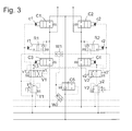
- Fig. 3 shows a valve assembly according to a second embodiment of the invention.
- the lines P, T, Px, Ls, the valves C1 to C4, Y1, Y2 and R1, R2 and the individual pressure compensator C5 are the same as in Fig. 1 and will not be explained again.
- a major difference between the design of the Fig. 3 and those of Fig. 1 are additional directional valves V1, V2.
- the directional control valve V1 connects the controlled port y1 of the pressure reducing valve Y1 with control terminals c3, v2 of the directional control valves C3 and V2 and the control terminals c1, r1 of the directional control valves C1, R1 with the unpressurized line T.
- the directional control valve V1 is switchable to a position in which it Control terminals c1, r1 with the pressure reducing valve Y1 and the control terminals c3, v2 with the non-pressurized line T connects.
- both pressure-reducing valves Y1, Y2 are closed, the directional control valves C1 to C4 are also blocked.
- the pressure reducing valve Y1 is opened and the pressure at its controlled port y1 rises, this first leads to the opening of C3 so that pressurized fluid can flow away from the consumer via the consumer side port A and to switch from V2 to its high pressure state.
- the pressure reducing valve Y2 is opened, this leads to the opening of C2, so that high pressure appears on the consumer side port B.
- R2 switches, so that this high pressure spreads to the load pressure signaling line LS and controls the operation of the individual pressure compensator C5.
- a load-independent regulated pressure fluid flow over port B to the consumer, and a complementary current returns from the consumer via port A to the tank.
- the Fig. 3 shows two control inputs to the directional valves V1, V2, an input v1 and v2, which, as mentioned above, is connected to an output of the respective other directional valve V2 or V1, and an input v1 'or v2', via which Output pressure of each directional valve V1, V2 is returned to it itself.
- both pressure reducing valves Y1, Y2 are simultaneously opened, the influences of the pressures at these two control ports v1 and v1 'and v2 and v2' cancel each other, and the directional valves V1, V2 remain in the in Fig. 3 shown rest position.
- valves C3, C4 open valves C1, C2 remain closed.
- valve assembly of the Fig. 3 To operate a double-acting consumer, which is connected to both consumer-side terminals A, B, there is the ability to independently control two single-acting consumers when the required to switch the directional control valve V1 and V2 control pressure is lower than that for opening the directional valves C1 to C4 required.
- the control pressure required for switching over the directional control valves V1, V2 can amount to approximately 3 bar, while the directional control valves C1 to C4 only start to open at a control pressure of 5 bar or above and are completely open at a control pressure of approximately 20 bar.
- Fig. 4 shows a third embodiment of the valve assembly, which differs from that of Fig. 1 by the addition of two hydraulically controlled shuttle valves F1, F2 different.
- the shuttle valves F1, F2 are respectively connected upstream of the control ports c1, c2 of the directional control valves C1 and C2, controlled by the pressure reducing valve Y2 either with the controlled port y1 of Y1 or with the unpressurized line T or c2 controlled by Y1 with y2 or to connect with the non-pressurized line T.
- the shuttle valves F1, F2 serve as the directional valves V1, V2 of Fig. 3 to allow opening of both the flow control valves C3, C4 controlling the drain, while at the same time keeping closed the directional control valves C1, C2 controlling the inlet to the consumer, thus bringing about a floating state of the consumer.
- the shuttle valve F1 controlled via this port connects the control port c1 to y1.
- the pressure reducing valve Y1 is opened while Y2 is closed, it rises as in the embodiment of Fig. 1 the pressure at the control terminals c1 and c4, and a double-acting consumer connected to the terminals A, B are driven in a first direction.
- the directional control valves C2, C3 open, and the consumer is driven in the opposite direction.
Landscapes
- Engineering & Computer Science (AREA)
- Physics & Mathematics (AREA)
- Fluid Mechanics (AREA)
- Mechanical Engineering (AREA)
- General Engineering & Computer Science (AREA)
- Fluid-Pressure Circuits (AREA)
- Multiple-Way Valves (AREA)
- Valve Housings (AREA)
Abstract
Description
Die vorliegende Erfindung betrifft eine Ventilbaugruppe für die - insbesondere lastunabhängige - Ansteuerung wenigstens eines Verbrauchers wie etwa eines Hydraulikzylinders, eines Hydraulikmotors oder dergleichen. Anwendungen für eine solche Ventilbaugruppe liegen insbesondere auf dem Gebiet der landwirtschaftlichen Maschinen mit hydraulisch angetriebenen oder verstellbaren Aggregaten oder der Baumaschinen.The present invention relates to a valve assembly for the - in particular load-independent - control of at least one consumer such as a hydraulic cylinder, a hydraulic motor or the like. Applications for such a valve assembly are particularly in the field of agricultural machinery with hydraulically driven or adjustable units or construction equipment.
Aus
Um einen hohen Druck an den verbraucherseitigen Ausgängen aufrecht erhalten zu können, der den Verbraucher in einer eingestellten Position fixiert, auch wenn die Pumpe inaktiv ist, sind zwischen der ersten und zweiten Steuerkante und den zwei verbraucherseitigen Anschlüssen zwei Rückschlagventile vorgesehen. Da der gesamte Zustrom von Hydrauliköl zum Verbraucher eines der beiden Rückschlagventile passieren muss, beeinträchtigt der dabei auftretende Druckabfall den Wirkungsgrad einer die bekannte Ventilgruppe verwendenden hydraulischen Maschine.In order to maintain a high pressure at the consumer-side outputs, which fixes the consumer in a set position, even when the pump is inactive, two check valves are provided between the first and second control edge and the two consumer-side ports. Since the entire influx of hydraulic oil to the load must pass through one of the two check valves, the pressure drop that occurs thereby adversely affects the efficiency of a hydraulic machine using the known valve group.
Die bekannte Ventilbaugruppe kann zur lastdruckunabhängigen Versorgung eines Verbrauchers eingesetzt werden, indem der dem Verbraucher zufließende Lastdruck am Eingang eines der Rückschlagventile abgegriffen und über eine Lastdruckmeldeleitung einem Kompensator am pumpenseitigen Anschluss der Ventilbaugruppe und gegebenenfalls einem Regler der Pumpe zugeführt wird. Um in einem Ruhezustand den Kompensator zuverlässig gesperrt bzw. die Pumpe ausgeschaltet zu halten, muss der Druck auf der Lastdruckmeldeleitung zuverlässig gleich dem Tankdruck gehalten werden, trotz eventuell hoher Drücke in anderen Teilen der Ventilbaugruppe. Um dies zu gewährleisten, sind die den Strom des Druckfluids zwischen dem Pumpenanschluss und den verbraucherseitigen Anschlüssen kontrollierenden ersten und zweiten Steuerkanten mit jeweils als eine Hauptsteuerkante in einem Wegeventil mit einer Hilfssteuerkante zusammengefasst, wobei die Hilfssteuerkante jedes Wegeventils im gesperrten Zustand der Hauptsteuerkante die Lastdruckmeldeleitung über eine Leckölrückführung mit dem Tank verbindet. Die Hauptsteuerkanten der Wegeventile müssen großzügig bemessen sein, um den gesamten Ölstrom zwischen Pumpe und Verbraucher mit geringem Druckabfall passieren zu lassen. Durch die Integration der Hilfssteuerkanten in diese Wegeventile nimmt deren Platzbedarf noch weiter zu.The known valve assembly can be used for load pressure independent supply of a consumer by the load flowing to the load load at the input of one of the check valves and fed via a load pressure signaling line a compensator on the pump side connection of the valve assembly and optionally a regulator of the pump. In order to reliably shut off the compensator in an idle state or to keep the pump switched off, the pressure on the load pressure signaling line must be reliably equal to the tank pressure despite possible high pressures in other parts of the valve assembly. To ensure this, the first and second control edges controlling the flow of the pressurized fluid between the pump port and the consumer-side ports are each combined as a main control edge in a directional control valve with an auxiliary control edge, the auxiliary control edge of each directional control valve in the locked state of the main control edge over the load pressure signaling line Leakage oil return connects to the tank. The main control edges of the directional control valves must be generously dimensioned to allow the entire flow of oil between pump and consumer to pass with a slight pressure drop. The integration of the auxiliary control edges in these directional control valves increases their space requirements even further.
Eine Aufgabe der Erfindung ist, eine Ventilbaugruppe für die Ansteuerung wenigstens eines Verbrauchers zu schaffen, in der interne Druckverluste minimiert sind und die somit einen Betrieb des Verbrauchers mit hohem Wirkungsgrad ermöglicht.An object of the invention is to provide a valve assembly for driving at least one consumer, in which internal pressure losses are minimized and thus enables operation of the consumer with high efficiency.
Die Aufgabe wird gelöst, indem bei einer Ventilbaugruppe mit zwei verbraucherseitigen Anschlüssen, einem Pumpen- und einem Tankanschluss und mit vier jeweils über einen Steueranschluss hydraulisch angesteuerten Steuerkanten, von denen eine erste den Pumpenanschluss und den ersten verbraucherseitigen Anschluss, die zweite den Pumpenanschluss und den zweiten verbraucherseitigen Anschluss, die dritte den ersten verbraucherseitigen Anschluss und den Tankanschluss und die vierte den zweiten verbraucherseitigen Anschluss und den Tankanschluss verbindet, ein erstes und ein zweites Vorsteuerventil zum Ansteuern der Steueranschlüsse von je zwei der Steuerkanten vorgesehen sind. Indem somit die herkömmliche Ansteuerung der dritten und vierten Steuerkanten durch den am Ausgang der ersten und zweiten Steuerkante herrschenden Druck entfällt, sind keine Rückschlagventile mehr erforderlich, um eine Druckdifferenz zwischen einem verbraucherseitigen Anschluss und dem Steueranschluss der dritten oder vierten Steuerkante aufrecht zu erhalten. Mit dem Wegfall der Rückschlagventile entfällt auch der mit ihnen verbundene Druckabfall, was den Wirkungsgrad des Verbrauchers verbessert. Indem jedes Vorsteuerventil nicht nur eine, sondern zwei Steuerkanten steuert, kann auch die zum Betrieb der Vorsteuerventile erforderliche Durchsatz an Hydraulikfluid und infolgedessen die mit dem Betrieb der Vorsteuerventile verbundene Verlustleistung klein gehalten werden.The object is achieved by providing a valve assembly with two consumer-side terminals, a pump and a tank connection and four each hydraulically controlled via a control terminal control edges, of which a first pump port and the first consumer-side port, the second pump port and the second consumer-side connection, the third the first consumer-side connection and the tank connection and the fourth the second consumer side Connection and the tank connection connects, a first and a second pilot valve for driving the control terminals of each two of the control edges are provided. By thus eliminating the conventional control of the third and fourth control edges by the prevailing at the output of the first and second control edge pressure, no check valves are required to maintain a pressure difference between a consumer-side terminal and the control terminal of the third or fourth control edge. With the elimination of the check valves also eliminates the associated pressure drop, which improves the efficiency of the consumer. By controlling each pilot valve not only one, but two control edges, and the required to operate the pilot valves throughput of hydraulic fluid and consequently associated with the operation of the pilot valves power loss can be kept small.
Es gibt verschiedene Möglichkeiten, die Steuerkanten den Vorsteuerventilen zuzuordnen. Einer ersten, einfachen Ausgestaltung zufolge sind die Steueranschlüsse der ersten und vierten Steuerkante parallel mit einem Ausgang des ersten Vorsteuerventils und die Steueranschlüsse der zweiten und dritten Steuerkante parallel mit einem Ausgang des zweiten Vorsteuerventils verbunden, um jeweils gleichzeitig die erste und vierte Steuerkante zu öffnen und so einen doppelt wirkenden Verbraucher in einer ersten Richtung anzutreiben, oder die zweite und dritte Steuerkante zu öffnen und den Verbraucher in entgegengesetzter Richtung anzutreiben.There are several ways to assign the control edges to the pilot valves. According to a first simple embodiment, the control ports of the first and fourth control edges are connected in parallel with an output of the first pilot valve and the control ports of the second and third control edges are connected in parallel with an output of the second pilot valve to simultaneously open the first and fourth control edges, and so on To drive a double-acting consumer in a first direction, or to open the second and third control edge and drive the consumer in the opposite direction.
Einer zweiten, weiterentwickelten Ausgestaltung zufolge ist eine Schwimmstellung des Verbrauchers, in welcher er unter einer von außen auf ihn einwirkenden Kraft bewegbar ist, dadurch realisierbar, dass der ersten und der zweiten Steuerkante jeweils ein erstes bzw. zweites Schaltventil zugeordnet ist, das einen Steueranschluss der ersten bzw. Steuerkante wahlweise mit dem ersten bzw. zweiten Vorsteuerventil bzw. mit dem Tankanschluss verbindet. So kann über das erste Steuerventil je nach Stellung des zugeordneten ersten Schaltventils der Zufluss von Hydraulikfluid zu einem Verbraucher oder der Abfluss von diesem Verbraucher am ersten verbraucherseitigen Anschluss gesteuert werden. Durch koordinierte Betätigung beider Vorsteuerventile kann der Verbraucher in zwei entgegengesetzte Richtungen angetrieben werden.According to a second, further developed embodiment, a float position of the consumer, in which it is movable under a force acting on it from the outside, can be realized by respectively assigning a first and a second switching valve to the first and second control edges the first or control edge selectively connects to the first and second pilot valve or to the tank connection. Thus, via the first control valve, depending on the position of the associated first switching valve, the inflow of hydraulic fluid to a consumer or the outflow from this consumer at the first consumer-side connection can be controlled. Coordinated actuation of both pilot valves allows the consumer to be driven in two opposite directions.
Bei den Schaltventilen kann es sich um Wechselventile oder um Wegeventile handeln. Wenn die Schaltventile als Wegeventile ausgeführt sind, kann insbesondere das erste Wegeventil das erste Vorsteuerventil wahlweise mit je einem der Steueranschlüsse seiner zwei zugeordneten Steuerkanten, insbesondere der ersten und dritten Steuerkante verbinden, während das zweite Wegeventil das zweite Vorsteuerventil wahlweise mit je einem der Steueranschlüsse seiner zwei zugeordneten Steuerkanten, insbesondere der zweiten und vierten Steuerkante, verbindet. So kann zum Beispiel ein vom ersten Vorsteuerventil ausgegebener Druck über das erste Wegeventil einerseits an die dritte Steuerkante weitergegeben werden, um ein Abfließen von Hydraulikfluid vom ersten verbraucherseitigen Anschluss zum Tankanschluss zu ermöglichen, und gleichzeitig das zweite Wegeventil in eine Stellung versetzen, in der es einen am Ausgang des zweiten Vorsteuerventils bestehenden Druck an den Steuereingang der zweiten Steuerkante weitergibt, um so einen Zufluss von Hydraulikfluid zum Verbraucher über den zweiten verbraucherseitigen Anschluss zu ermöglichen.The switching valves may be changeover valves or directional control valves. If the switching valves are designed as directional control valves, in particular the first directional control valve can selectively connect to one of the control terminals of its two associated control edges, in particular the first and third control edge, while the second directional control valve, the second pilot valve with either one of the control terminals of its two associated control edges, in particular the second and fourth control edge connects. Thus, for example, a pressure output by the first pilot valve can be forwarded via the first directional control valve, on the one hand, to the third control edge in order to prevent hydraulic fluid from flowing away from the first control valve allow consumer-side connection to the tank connection, and at the same time enable the second directional control valve in a position in which it passes a present at the output of the second pilot valve pressure to the control input of the second control edge, so as to an inflow of hydraulic fluid to the consumer via the second consumer-side connection enable.
Ein zum Umschalten des ersten und zweiten Schaltventils erforderlicher Ausgangsdruck der Vorsteuerventile ist vorzugsweise niedriger als der zum Öffnen der Steuerkanten erforderliche Ausgangsdruck. So können, indem der Druck am Ausgang beider Vorsteuerventile koordiniert erhöht wird, zunächst die beiden Schaltventile geschaltet werden. Ein Umschalten der Schaltventile bei offenen Steuerkanten ist dadurch ausgeschlossen.A required for switching the first and second switching valve output pressure of the pilot valves is preferably lower than the output pressure required to open the control edges. Thus, by coordinately increasing the pressure at the outlet of both pilot valves, the two switching valves can first be switched. A switching of the switching valves at open control edges is thereby excluded.
Vorzugsweise haben die zwei Schaltventile jeweils einen zweiten Steuereingang, auf den einer ihrer Ausgänge zurückgeführt ist, so dass der an dem Ausgang herrschende Druck dem am ersten Steuereingang anliegenden Druck entgegenwirkt. Dieser am zweiten Steuereingang rückgeführte Druck kann das Schaltventil in der Stellung, die es auch in drucklosem Zustand einnimmt, trotz eines am ersten Steuereingang anliegenden Drucks sichern, so dass bei gleichzeitiger Druckbeaufschlagung beider Schaltventile diese ihre Schaltstellung nicht ändern.Preferably, the two switching valves each have a second control input to which one of its outputs is returned, so that the pressure prevailing at the output counteracts the pressure applied to the first control input pressure. This recirculated at the second control input pressure can secure the switching valve in the position which it assumes even in a depressurized state, despite a pressure applied to the first control input, so that at the same time pressurizing both switching valves that do not change their switching position.
Die Vorsteuerventile sind vorzugsweise als Proportionaldruckminderventile ausgeführt.The pilot valves are preferably designed as proportional pressure reducing valves.
Um eine lastunabhängige Steuerung eines angeschlossenen Verbrauchers zu ermöglichen, ist vorzugsweise eine durch den an einem der verbraucherseitigen Anschlüsse herrschenden Druck gesteuerte Individualdruckwaage zwischen den Pumpenanschluss und die erste und zweite Steuerkante eingefügt.In order to enable load-independent control of a connected consumer, an individual pressure compensator controlled by the pressure prevailing at one of the consumer-side connections is preferably inserted between the pump connection and the first and second control edges.
Mittels eines entsperrbaren Rückschlagventils zwischen einem Steuereingang der Individualdruckwaage und jedem verbraucherseitigen Anschluss kann der jeweils höchste an den verbraucherseitigen Anschlüssen anliegende Druck an die Individualdruckwaage weitergeleitet werden, ohne dadurch den am jeweils anderen verbraucherseitigen Anschluss vorliegenden Druck zu verändern. Bei ausgeschalteter Pumpe verhindern die Rückschlagventile einen Fluss von Druckfluid von einem verbraucherseitigen Anschluss zum anderen über die Lastdruckmeldeleitung und damit ein ungewolltes Nachgeben des Verbrauchers unter einer äußeren Last. Eine Entsperrung eines der Rückschlagventils ermöglicht es, auch einen abnehmenden Druck korrekt von einem verbraucherseitigen Anschluss zur Individualdruckwaage zu übertragen.By means of a pilot-operated check valve between a control input of the individual pressure balance and each consumer-side connection, the highest pressure applied to the consumer-side connections can be forwarded to the individual pressure balance, without thereby changing the pressure present at the other consumer-side connection. When the pump is turned off, the check valves prevent a flow of pressurized fluid from one consumer-side port to the other via the load pressure signaling line and thus an unwilling yielding of the consumer under an external load. Unlocking one of the check valve makes it possible to transmit a decreasing pressure correctly from a consumer-side port to the individual pressure compensator.
Um die Entsperrung der entsperrbaren Rückschlagventile zu steuern, kann zweckmäßigerweise ein Ausgabesignal jeweils eines der Vorsteuerventile genutzt werden.In order to control the unlocking of the pilot-operated check valves, it is expedient to use one output signal each of one of the pilot valves.
Wie bereits eingangs erwähnt, muss im Stillstand eine unkontrollierte Druckerhöhung am Steueranschluss der Individualdruckwaage verhindert werden, um eine Fehlsteuerung der Pumpe bzw. der Vorsteuerventile zu vermeiden. Um dies zu gewährleisten, sind vorteilhafterweise die entsperrbaren Rückschlagventile eingerichtet, um im Sperrzustand den Steueranschluss der Individualdruckwaage mit dem Tankanschluss zu verbinden. Da die entsperrbaren Rückschlagventile nur einen kleinen Bruchteil desjenigen Durchsatzes bewältigen müssen, der über die ersten bis vierten Steuerkanten läuft, können diese entsperrbaren Rückschlagventile klein dimensioniert sein, und dementsprechend wenig Platz erfordert auch die Implementierung einer Verbindung des Steueranschlusses der Individualdruckwaage mit dem Tankanschluss über die entsperrbaren Rückschlagventile.As already mentioned, an uncontrolled pressure increase at the control connection of the individual pressure compensator must be prevented at standstill in order to control the pump or pilot valves incorrectly to avoid. To ensure this, the unlockable check valves are advantageously arranged to connect the control port of the individual pressure compensator with the tank connection in the locked state. Since the pilot-operated check valves only have to cope with a small fraction of the throughput that runs over the first to fourth control edges, these pilot-operated check valves can be dimensioned small, and correspondingly little space requires the implementation of a connection of the control terminal of the individual pressure compensator with the tank connection via the unlockable check valves.
Ein in die Individualdruckwaage integriertes Rückschlagventil ermöglicht es, bei einem Ausfall der Pumpe einen plötzlichen Druckabfall an den verbraucherseitigen Anschlüssen und damit eine unkontrollierte Bewegung des Verbrauchers unter Last zu vermeiden.A check valve integrated in the individual pressure compensator makes it possible, in the event of a failure of the pump, to avoid a sudden drop in pressure at the connections on the consumer side and thus an uncontrolled movement of the load under load.
Erfindungsgegenstand ist auch ein Traktor mit einer Ventilbaugruppe der oben beschriebenen Art, an die ein hydraulisch verstellbares oder angetriebenes Aggregat wie etwa ein Pflug oder ein Mähwerk anschließbar ist.Subject of the invention is also a tractor with a valve assembly of the type described above, to which a hydraulically adjustable or driven unit such as a plow or a mower can be connected.
Weitere Merkmale und Vorteile der Erfindung ergeben sich aus der nachfolgenden Beschreibung von Ausführungsbeispielen unter Bezugnahme auf die beigefügten Figuren. Es zeigen:
- Fig. 1
- ein Hydraulikdiagramm einer Ventilan- ordnung gemäß einer ersten Ausgestal- tung der Erfindung;
- Fig. 2
- einen schematischen Schnitt durch eines der in
Fig. 1 gezeigten Ventile; - Fig. 3
- ein Hydraulikdiagramm einer Ventilan- ordnung gemäß einer zweiten Ausgestal- tung der Erfindung; und
- Fig. 4
- ein Hydraulikdiagramm gemäß einer drit- ten Ausgestaltung der Erfindung.
- Fig. 1
- a hydraulic diagram of a valve assembly according to a first embodiment of the invention;
- Fig. 2
- a schematic section through one of in
Fig. 1 shown valves; - Fig. 3
- a hydraulic diagram of a valve assembly according to a second embodiment of the invention; and
- Fig. 4
- a hydraulic diagram according to a third embodiment of the invention.
Eine von der Hochdruckleitung P ausgehende Verzweigung P1 verläuft über eine durch den auf der Lastdruckmeldeleitung LS anstehenden Druck gesteuerten Individualdruckwaage C5 zu zwei hydraulisch vorgesteuerten, durch eine Feder rückgestellten Wegeventilen C1 und C2. Zwei verbraucherseitige Anschlüsse A, B sind mit Ausgängen der beiden Wegeventile C1, C2 verbunden. Die Wegeventile sind in Sitzbauweise ausgeführt und so angeordnet, dass ihr Ventilkörper jeweils durch einen Überdruck am verbraucherseitigen Anschluss gegen seinen Sitz gepresst wird. Die Wegeventile C1, C2 sind daher absolut dicht gegen einen hohen Druck an einem der verbraucherseitigen Anschlüsse, der auftreten kann, wenn eine äußere Last auf einen angeschlossenen Verbraucher wirkt, z.B. auf einen Hydraulikzylinder, der einen an den Traktor angeschlossener Pflug für Straßen- oder Rangierfahrt in einer vom Boden abgehobenen Stellung hält oder ihn gegen den Boden presst, um die Pflugschar beim Pflügen in einer gewünschten Tiefe zu halten.A branch P1 originating from the high-pressure line P extends via an individual pressure compensator C5 controlled by the pressure present on the load pressure signaling line LS to two hydraulically piloted directional valves C1 and C2 reset by a spring. Two consumer-side ports A, B are connected to outputs of the two-way valves C1, C2. The directional control valves are designed in seat construction and arranged so that their valve body is pressed in each case by an overpressure on the consumer-side connection against its seat. The directional control valves C1, C2 are therefore absolutely tight against a high pressure at one of the consumer-side ports, which may occur when an external load acts on a connected consumer, e.g. to a hydraulic cylinder that holds a plow connected to the tractor for road or shunting in a raised position from the ground or presses it against the ground to keep the ploughshare at a desired depth when plowing.
Zwei weitere Wegeventile C3, C4 verbinden die verbraucherseitigen Anschlüsse A, B mit der drucklosen Leitung T.Two further directional control valves C3, C4 connect the consumer-side ports A, B with the unpressurized line T.
Die Wegeventile C1 bis C4 sind in
Zwei Proportionaldruckminderventile Y1, Y2 dienen als Vorsteuerventile zum Erzeugen dieses Steuerdrucks. Die Druckminderventile Y1, Y2 sind mit der Steuerdruckleitung Px und der drucklosen Leitung T verbunden und haben jeweils einen gesteuerten Anschluss y1, y2, dessen Druck auf elektrischem Wege zwischen den Drücken der Leitungen Px und T kontinuierlich einstellbar ist. Das Druckminderventil Y1 steuert den Druck auf einer Vorsteuerleitung 1, die Steueranschlüsse c1, c4 der Ventile C1, und C4 verbindet; das Druckminderventil Y2 steuert in analoger Weise über eine Vorsteuerleitung 2 die Ventile C2 und C3.Two proportional pressure reducing valves Y1, Y2 serve as pilot valves for generating this control pressure. The pressure reducing valves Y1, Y2 are connected to the control pressure line Px and the unpressurized line T and each have a controlled connection y1, y2, the pressure of which is continuously adjustable electrically between the pressures of the lines Px and T. The pressure reducing valve Y1 controls the pressure on a pilot line 1 connecting control ports c1, c4 of the valves C1, and C4; the pressure reducing valve Y2 controls in an analogous manner via a
Entsperrbare Rückschlagventile R1, R2 haben jeweils einen Steueranschluss r1 bzw. r2, der mit der Vorsteuerleitung 1 bzw. 2 verbunden ist, einen Einlass, der mit dem verbrauchserseitigen Anschluss A bzw. B verbunden ist, und zwei Auslässe, die mit der drucklosen Leitung T bzw. über Leitungszweige LS1 bzw. LS2 und ein Wechselventil W1 mit der Lastdruckmeldeleitung LS verbunden sind.Unlockable check valves R1, R2 each have a control port r1 and r2, respectively, connected to the
Ein zweites in die Lastdruckmeldeleitung LS eingefügtes Wechselventil W2 erlaubt es, wahlweise den am Steueranschluss c5 der Individualdruckwaage C5 der in der Fig. gezeigten Druck oder den einer anderen, zur in der Fig. gezeigten parallel an die Leitungen P, T, Px, LS geschalteten Ventilbaugruppe zum Regeln einer die Leitung P speisenden externen Pumpe durchzuschalten.A second change-over valve W2 inserted in the load-pressure signaling line LS allows either the pressure shown in the figure at the control port c5 of the individual pressure compensator C5 or that connected to the lines P, T, Px, LS shown in parallel in FIG Switch valve assembly for controlling an external pump supplying the line P.
In der in
Wenn eines der beiden Druckminderventile, zum Beispiel Y1, geöffnet wird, steigt der Druck auf der Vorsteuerleitung 1, und die Wegeventile C1, C4 öffnen proportional zu diesem Druck. Der Ausgangsdruck der Druckwaage C5 liegt somit am Anschluss A an, während über den Anschluss B Druckfluid zum Tank abfließen kann. Gleichzeitig führt der hohe Druck auf der Vorsteuerleitung 1 zum Schalten des Wegeventils R1 in eine Stellung, in der es den Anschluss A mit dem Zweig LS1 verbindet und gleichzeitig die Verbindung des Zweigs LS1 zur drucklosen Leitung T unterbricht. Die Lastdruckmeldeleitung LS führt somit den am Anschluss A herrschenden Druck. Die Druckwaage C5 regelt in an sich bekannter Weise den durch sie hindurch von der Pumpe zum Anschluss A verlaufenden Fluidstrom derart, dass sich eine konstante Druckdifferenz zwischen dem Ausgang der Druckwaage C5 und ihrem mit der Lastdruckmeldeleitung LS verbundenen Steuereingang ergibt. Diese Druckdifferenz ist im Wesentlichen gleich dem Druckabfall an der Steuerkante des Wegeventils C1, und es ergibt sich eine direkter linearer Zusammenhang zwischen dem Öffnungsquerschnitt an der Steuerkante des Wegeventils C1 und dem dem Verbraucher über den Anschluss A zugeführten Volumenstrom.When one of the two pressure reducing valves, for example Y1, is opened, the pressure on the pilot control line 1 increases, and the directional control valves C1, C4 open in proportion to this pressure. The output pressure of the pressure compensator C5 is therefore at the port A, while via the port B pressurized fluid can flow to the tank. At the same time, the high pressure on the pilot control line 1 leads to switching of the directional control valve R1 into a position in which it connects the connection A to the branch LS1 and at the same time interrupts the connection of the branch LS1 to the unpressurized line T. The load pressure signaling line LS thus carries the pressure prevailing at port A. The pressure compensator C5 regulates in a conventional manner that through them from the pump to the port A running fluid flow such that there is a constant pressure difference between the output of the pressure compensator C5 and its connected to the load pressure signaling line LS control input. This pressure difference is substantially equal to the pressure drop at the control edge of the directional control valve C1, and there is a direct linear relationship between the opening cross section at the control edge of the directional control valve C1 and the volume flow supplied to the consumer via the connection A.
Wenn aufgrund einer Störung der Pumpe der Druck auf der Hochdruckleitung P abfällt oder eine auf den Verbraucher einwirkende externe Kraft dazu führt, dass der Druck am verbraucherseitigen Anschluss A höher wird als der auf der Leitung P, dann bewirkt ein integriertes Rückschlagventil 3 eine Sperrung der Individualdruckwaage C5. Es kommt daher in diesen Fällen nicht zu einer rückläufigen Bewegung des Verbrauchers, sondern dieser verharrt in der einmal erreichten Stellung.If due to a malfunction of the pump, the pressure on the high-pressure line P drops or an external force acting on the consumer causes the pressure at the consumer-side terminal A is higher than that on the line P, then an integrated check valve 3 causes a blocking of the individual pressure compensator C5. In these cases, therefore, there is no downward movement of the consumer, but this remains in the position once reached.
Der Einsatz 15 umfasst eine axiale Bohrung 19 sowie wenigstens drei die axiale Bohrung 19 kreuzende radiale Bohrungen 20, 21, 22. Die Bohrung 20 mündet in die Kammer 14, die Bohrung 21 ist mit einem der Zweige LS1 bzw. LS2 der Lastdruckmeldeleitung LS verbunden, und die Bohrung 22 mit einem der verbraucherseitigen Anschlüsse A bzw. B. In der Bohrung 19 ist ein Dorn 23 axial verschiebbar. In der in
Unter dem Einfluss eines positiven Steuerdrucks an der Rückseite 12 des Kolbens 11 bewegt sich dieser in der Figur nach links und nimmt dabei den Dorn 23 mit. Ein Fußabschnitt 28 des Dorns 23, dessen Querschnitt exakt dem der Bohrung 19 entspricht, rückt dabei in den die Bohrungen 20, 21 verbindenden Abschnitt der axialen Bohrung 19 ein und versperrt diesen. Damit ist die Verbindung zwischen der Lastdruckmeldeleitung LS und der drucklosen Kammer 14 unterbrochen. Anschließend stößt die Spitze 24 gegen die Kugel 26 und hebt sie vom Ventilsitz 27 ab. Damit ist das Rückschlagventil entsperrt, und die Lastdruckmeldeleitung LS nimmt den am verbraucherseitigen Anschluss A oder B herrschenden Druck an. Indem der Dorn 23 zuerst die Verbindung zur Kammer 14 versperrt, bevor er das Rückschlagventil entsperrt, ist ein unkontrollierter Abfluss von Druckfluid vom verbraucherseitigen Anschluss A oder B zum Tank über das Wegeventil R1 oder R2 ausgeschlossen.Under the influence of a positive control pressure on the
Wie man sieht, ist der Querschnitt des Kolbens 11 um ein Vielfaches größer als der Durchmesser der Kugel 26, so dass ein relativ geringer Steuerdruck an der Kolbenrückseite 12 genügt, um die Kugel 26 von ihrem Sitz 27 zu lösen, auch wenn diese durch einen hohen Druck am geräteseitigen Anschluss gegen den Sitz 27 gepresst wird.As can be seen, the cross-section of the
Sind beide Druckminderventile Y1, Y2 geschlossen, so sperren auch die Wegeventile C1 bis C4. Wenn das Druckminderventil Y1 geöffnet wird und der Druck an seinem gesteuerten Anschluss y1 ansteigt, führt dies zunächst zum Öffnen von C3, so dass Druckfluid vom Verbraucher über den verbraucherseitigen Anschluss A abfließen kann, und zum Umschalten von V2 in seinen Hochdruckzustand. Wenn nun auch das Druckminderventil Y2 geöffnet wird, führt dies zum Öffnen von C2, so dass hoher Druck am verbraucherseitigen Anschluss B erscheint. Gleichzeitig schaltet R2, so dass dieser hohe Druck sich auf die Lastdruckmeldeleitung LS ausbreitet und den Betrieb der Individualdruckwaage C5 steuert. Somit fließt ein lastunabhängig geregelter Druckfluidstrom über den Anschluss B zum Verbraucher, und ein komplementärer Strom kehrt vom Verbraucher über den Anschluss A zum Tank zurück.If both pressure-reducing valves Y1, Y2 are closed, the directional control valves C1 to C4 are also blocked. When the pressure reducing valve Y1 is opened and the pressure at its controlled port y1 rises, this first leads to the opening of C3 so that pressurized fluid can flow away from the consumer via the consumer side port A and to switch from V2 to its high pressure state. Now, if the pressure reducing valve Y2 is opened, this leads to the opening of C2, so that high pressure appears on the consumer side port B. At the same time R2 switches, so that this high pressure spreads to the load pressure signaling line LS and controls the operation of the individual pressure compensator C5. Thus flows a load-independent regulated pressure fluid flow over port B to the consumer, and a complementary current returns from the consumer via port A to the tank.
Werden die Druckminderventile Y1, Y2 in umgekehrter Reihenfolge geöffnet, so erscheint Hochdruck am Anschluss A, der Anschluss B kommuniziert mit der drucklosen Leitung T, und der Verbraucher wird in entgegengesetzter Richtung angetrieben.If the pressure reducing valves Y1, Y2 are opened in the reverse order, high pressure appears at port A, port B communicates with the unpressurized line T, and the consumer is driven in the opposite direction.
Die
Alternativ zu der oben betrachteten Möglichkeit, mit der Ventilbaugruppe der
Um den Verbraucher am Anschluss A auszufahren, muss es möglich sein, C1 zu öffnen, während C2 bis C4 geschlossen bleiben. Dies gelingt, indem zunächst am gesteuerten Anschluss y2 von Y2 ein Druck von z.B. 4bar eingestellt wird. Dieser veranlasst das Wegeventil V1, umzuschalten, reicht aber noch nicht, um C4 zu öffnen. V1 verbindet nun den gesteuerten Anschluss y1 mit c1, so dass durch Öffnen von Y1 C1 geöffnet werden kann.To extend the load on port A, it must be possible to open C1 while keeping C2 to C4 closed. This is achieved by first applying a pressure of Y2 to the controlled port y2 of Y2 eg 4bar is set. This causes the directional control valve V1 to switch but is not yet enough to open C4. V1 now connects the controlled port y1 to c1 so that opening Y1 opens C1.
Dass in genau analoger Weise auch ein Verbraucher am Anschluss B gesteuert werden kann, versteht sich aufgrund der Symmetrie der Ventilbaugruppe ohne eingehende Erläuterungen.The fact that a consumer can be controlled at port B in exactly the same way is due to the symmetry of the valve assembly without detailed explanations.
Wenn zum Beispiel der gesteuerte Anschluss y2 drucklos ist, verbindet das über diesen Anschluss gesteuerte Wechselventil F1 den Steueranschluss c1 mit y1. Wenn das Druckminderventil Y1 geöffnet wird, während Y2 geschlossen ist, steigt wie bei der Ausgestaltung der
- 11
- Vorsteuerleitungpilot line
- 22
- Vorsteuerleitungpilot line
- 33
- Rückschlagventilcheck valve
- 1010
- Gehäusecasing
- 1111
- Kolbenpiston
- 1212
- Rückseiteback
- 1313
- Vorderseitefront
- 1414
- Kammerchamber
- 1515
- Einsatzcommitment
- 1616
- Aussparungrecess
- 1717
- Vorsprunghead Start
- 1818
- Schraubenfedercoil spring
- 1919
- axiale Bohrungaxial bore
- 2020
- radiale Bohrungradial bore
- 2121
- radiale Bohrungradial bore
- 2222
- radiale Bohrungradial bore
- 2323
- Dornmandrel
- 2424
- Spitzetop
- 2525
- Federfeather
- 2626
- KugelBullet
- 2727
- Ventilsitzvalve seat
- 2828
- Fußabschnittfoot section
- AA
- verbraucherseiti- ger Anschlussconsumer-side connection
- BB
- verbrauchersei- tiger AnschlussConsumer connection
- C1-C4C1-C4
- Wegeventilway valve
- C5C5
- Individualdruck- waageIndividual pressure balance
- C1-c5C1-c5
- Steueranschluss von CiControl connection of Ci
- F1, F2F1, F2
- Wechselventilshuttle valve
- PP
- HochdruckleitungHigh-pressure line
- Pxpx
- Steuerdrucklei- tungControl pressure line
- R1, R2R1, R2
- entsperrbares Rückschlagventilunlockable check valve
- r1, r2r1, r2
- Steueranschluss von R1 bzw. R2Control connection of R1 or R2
- V1, V2V1, V2
- Wegeventilway valve
- v1, v2v1, v2
- Steueranschluss von V1 bzw. V2Control connection of V1 or V2
- W1, W2W1, W2
- Wechselventilshuttle valve
- Y1, Y2Y1, Y2
- Proportional- druckminderven- tilProportional pressure reducer valve
- y1, y2y1, y2
- gesteuerter An- schluss von Y1 bzw. Y2controlled connection of Y1 or Y2
Claims (15)
Applications Claiming Priority (1)
| Application Number | Priority Date | Filing Date | Title |
|---|---|---|---|
| DE102009052257A DE102009052257A1 (en) | 2009-11-06 | 2009-11-06 | valve assembly |
Publications (3)
| Publication Number | Publication Date |
|---|---|
| EP2320094A2 true EP2320094A2 (en) | 2011-05-11 |
| EP2320094A3 EP2320094A3 (en) | 2014-08-06 |
| EP2320094B1 EP2320094B1 (en) | 2017-04-19 |
Family
ID=43852896
Family Applications (1)
| Application Number | Title | Priority Date | Filing Date |
|---|---|---|---|
| EP10188785.9A Active EP2320094B1 (en) | 2009-11-06 | 2010-10-26 | Valve assembly |
Country Status (3)
| Country | Link |
|---|---|
| EP (1) | EP2320094B1 (en) |
| DE (1) | DE102009052257A1 (en) |
| RU (1) | RU2529543C2 (en) |
Cited By (5)
| Publication number | Priority date | Publication date | Assignee | Title |
|---|---|---|---|---|
| WO2016091528A1 (en) * | 2014-12-08 | 2016-06-16 | Robert Bosch Gmbh | Hydraulic valve arrangement, hydraulic valve block with such a valve arrangement, and hydraulic drive comprising such a valve block |
| US11143211B1 (en) | 2021-01-29 | 2021-10-12 | Cnh Industrial America Llc | System and method for controlling hydraulic fluid flow within a work vehicle |
| US11261582B1 (en) | 2021-01-29 | 2022-03-01 | Cnh Industrial America Llc | System and method for controlling hydraulic fluid flow within a work vehicle using flow control valves |
| US11313388B1 (en) | 2021-01-29 | 2022-04-26 | Cnh Industrial America Llc | System and method for controlling hydraulic fluid flow within a work vehicle |
| US11530524B2 (en) | 2021-01-29 | 2022-12-20 | Cnh Industrial America Llc | System and method for controlling hydraulic fluid flow within a work vehicle |
Families Citing this family (2)
| Publication number | Priority date | Publication date | Assignee | Title |
|---|---|---|---|---|
| CN102587950B (en) * | 2012-03-09 | 2014-07-23 | 中煤北京煤矿机械有限责任公司 | Double-buffering type pushing check valve |
| DE102020002960A1 (en) | 2020-05-16 | 2021-11-18 | Hydac Fluidtechnik Gmbh | System for braking a displacement-controlled drive system |
Citations (1)
| Publication number | Priority date | Publication date | Assignee | Title |
|---|---|---|---|---|
| EP0473030A1 (en) | 1990-08-31 | 1992-03-04 | Hydrolux S.A.R.L. | Proportional 4-way seat valve |
Family Cites Families (7)
| Publication number | Priority date | Publication date | Assignee | Title |
|---|---|---|---|---|
| US4362018A (en) * | 1980-06-12 | 1982-12-07 | Kobe Steel, Ltd. | Hydraulic rotation control circuit |
| JPS6011703A (en) * | 1983-07-01 | 1985-01-22 | Hitachi Constr Mach Co Ltd | Logic valve control equipment |
| DE102004063044B4 (en) * | 2004-12-22 | 2006-12-21 | Sauer-Danfoss Aps | Hydraulic control |
| DE102005029821A1 (en) * | 2005-04-04 | 2006-10-05 | Bosch Rexroth Ag | Valve has two slides which are spring-loaded towards center of bore and share common control system which allows pressure to be applied simultaneously to their front surfaces and to their rear surfaces, which are smaller in area |
| DE202005015923U1 (en) * | 2005-09-21 | 2005-12-08 | Wessel-Hydraulik Gmbh | Hydraulic switching arrangement for supply of double acting hydraulic consumer has one proportional valve for two pilot inputs of each control valve in respective lines to consumer |
| US20080295681A1 (en) * | 2007-05-31 | 2008-12-04 | Caterpillar Inc. | Hydraulic system having an external pressure compensator |
| DE102007054134A1 (en) * | 2007-11-14 | 2009-05-20 | Hydac Filtertechnik Gmbh | Hydraulic valve device |
-
2009
- 2009-11-06 DE DE102009052257A patent/DE102009052257A1/en not_active Withdrawn
-
2010
- 2010-10-26 EP EP10188785.9A patent/EP2320094B1/en active Active
- 2010-11-01 RU RU2010144400/03A patent/RU2529543C2/en active
Patent Citations (1)
| Publication number | Priority date | Publication date | Assignee | Title |
|---|---|---|---|---|
| EP0473030A1 (en) | 1990-08-31 | 1992-03-04 | Hydrolux S.A.R.L. | Proportional 4-way seat valve |
Cited By (5)
| Publication number | Priority date | Publication date | Assignee | Title |
|---|---|---|---|---|
| WO2016091528A1 (en) * | 2014-12-08 | 2016-06-16 | Robert Bosch Gmbh | Hydraulic valve arrangement, hydraulic valve block with such a valve arrangement, and hydraulic drive comprising such a valve block |
| US11143211B1 (en) | 2021-01-29 | 2021-10-12 | Cnh Industrial America Llc | System and method for controlling hydraulic fluid flow within a work vehicle |
| US11261582B1 (en) | 2021-01-29 | 2022-03-01 | Cnh Industrial America Llc | System and method for controlling hydraulic fluid flow within a work vehicle using flow control valves |
| US11313388B1 (en) | 2021-01-29 | 2022-04-26 | Cnh Industrial America Llc | System and method for controlling hydraulic fluid flow within a work vehicle |
| US11530524B2 (en) | 2021-01-29 | 2022-12-20 | Cnh Industrial America Llc | System and method for controlling hydraulic fluid flow within a work vehicle |
Also Published As
| Publication number | Publication date |
|---|---|
| DE102009052257A1 (en) | 2011-05-12 |
| RU2010144400A (en) | 2012-05-10 |
| EP2320094A3 (en) | 2014-08-06 |
| RU2529543C2 (en) | 2014-09-27 |
| EP2320094B1 (en) | 2017-04-19 |
Similar Documents
| Publication | Publication Date | Title |
|---|---|---|
| EP1915538B1 (en) | Circuit for controlling a double-action hydraulic drive cylinder | |
| EP2320094B1 (en) | Valve assembly | |
| DE102006003414B3 (en) | Hydraulic circuit arrangement | |
| EP2488764B1 (en) | Valve system | |
| EP2294331B1 (en) | Hydraulic valve device | |
| EP2092200B1 (en) | Hydraulic two-circuit system and interconnecting valve arrangement | |
| EP3058236B1 (en) | Control apparatus | |
| EP0620371A1 (en) | Hydraulic system for supply of open or closed hydraulic functions | |
| EP2636908A2 (en) | Control assembly | |
| WO2019214887A1 (en) | Valve arrangement for supplying a hydraulic consumer with pressure medium | |
| DE102014016639A1 (en) | Hydraulic valve arrangement with control function | |
| DE3710699C1 (en) | Hydraulic control device for a consumer group | |
| WO2005015030A1 (en) | Hydraulic control system for building machinery, particularly excavators | |
| DE4119333C2 (en) | Hydrostatic drive with a hydraulic motor arranged in an open circuit | |
| DE102014016642A1 (en) | Hydraulic valve arrangement with control function | |
| EP3236085B1 (en) | Amplifier valve for a closed-center-system working hydraulic system for an agricultural or civil engineering working machine | |
| EP3436705B1 (en) | Control device | |
| EP2157320B1 (en) | Hydraulic device for a hydro motor | |
| EP3398418A1 (en) | Hydraulic system of a machine usable in agriculture or civil engineering | |
| EP2891805A2 (en) | Control assembly and a control valve for such a control assembly | |
| DE102006032908A1 (en) | Multi-way valve block with mechanical and electro-hydraulic actuators, | |
| WO1997024534A1 (en) | Valve assembly | |
| DE102016212306A1 (en) | Intermediate block and compact axle with an intermediate block | |
| DE102016105159A1 (en) | Hydraulic system of a land or building usable vehicle | |
| WO1997028374A1 (en) | Hydraulic control device for pressure medium supply to several hydraulic consumers |
Legal Events
| Date | Code | Title | Description |
|---|---|---|---|
| PUAI | Public reference made under article 153(3) epc to a published international application that has entered the european phase |
Free format text: ORIGINAL CODE: 0009012 |
|
| AK | Designated contracting states |
Kind code of ref document: A2 Designated state(s): AL AT BE BG CH CY CZ DE DK EE ES FI FR GB GR HR HU IE IS IT LI LT LU LV MC MK MT NL NO PL PT RO RS SE SI SK SM TR |
|
| AX | Request for extension of the european patent |
Extension state: BA ME |
|
| PUAL | Search report despatched |
Free format text: ORIGINAL CODE: 0009013 |
|
| AK | Designated contracting states |
Kind code of ref document: A3 Designated state(s): AL AT BE BG CH CY CZ DE DK EE ES FI FR GB GR HR HU IE IS IT LI LT LU LV MC MK MT NL NO PL PT RO RS SE SI SK SM TR |
|
| AX | Request for extension of the european patent |
Extension state: BA ME |
|
| RIC1 | Information provided on ipc code assigned before grant |
Ipc: F15B 11/00 20060101AFI20140701BHEP |
|
| 17P | Request for examination filed |
Effective date: 20150206 |
|
| RBV | Designated contracting states (corrected) |
Designated state(s): AL AT BE BG CH CY CZ DE DK EE ES FI FR GB GR HR HU IE IS IT LI LT LU LV MC MK MT NL NO PL PT RO RS SE SI SK SM TR |
|
| GRAP | Despatch of communication of intention to grant a patent |
Free format text: ORIGINAL CODE: EPIDOSNIGR1 |
|
| INTG | Intention to grant announced |
Effective date: 20170109 |
|
| GRAS | Grant fee paid |
Free format text: ORIGINAL CODE: EPIDOSNIGR3 |
|
| GRAA | (expected) grant |
Free format text: ORIGINAL CODE: 0009210 |
|
| AK | Designated contracting states |
Kind code of ref document: B1 Designated state(s): AL AT BE BG CH CY CZ DE DK EE ES FI FR GB GR HR HU IE IS IT LI LT LU LV MC MK MT NL NO PL PT RO RS SE SI SK SM TR |
|
| REG | Reference to a national code |
Ref country code: GB Ref legal event code: FG4D Free format text: NOT ENGLISH |
|
| REG | Reference to a national code |
Ref country code: CH Ref legal event code: EP |
|
| REG | Reference to a national code |
Ref country code: AT Ref legal event code: REF Ref document number: 886256 Country of ref document: AT Kind code of ref document: T Effective date: 20170515 |
|
| REG | Reference to a national code |
Ref country code: IE Ref legal event code: FG4D Free format text: LANGUAGE OF EP DOCUMENT: GERMAN |
|
| REG | Reference to a national code |
Ref country code: DE Ref legal event code: R096 Ref document number: 502010013482 Country of ref document: DE |
|
| REG | Reference to a national code |
Ref country code: NL Ref legal event code: MP Effective date: 20170419 |
|
| REG | Reference to a national code |
Ref country code: LT Ref legal event code: MG4D |
|
| PG25 | Lapsed in a contracting state [announced via postgrant information from national office to epo] |
Ref country code: NL Free format text: LAPSE BECAUSE OF FAILURE TO SUBMIT A TRANSLATION OF THE DESCRIPTION OR TO PAY THE FEE WITHIN THE PRESCRIBED TIME-LIMIT Effective date: 20170419 |
|
| PG25 | Lapsed in a contracting state [announced via postgrant information from national office to epo] |
Ref country code: HR Free format text: LAPSE BECAUSE OF FAILURE TO SUBMIT A TRANSLATION OF THE DESCRIPTION OR TO PAY THE FEE WITHIN THE PRESCRIBED TIME-LIMIT Effective date: 20170419 Ref country code: ES Free format text: LAPSE BECAUSE OF FAILURE TO SUBMIT A TRANSLATION OF THE DESCRIPTION OR TO PAY THE FEE WITHIN THE PRESCRIBED TIME-LIMIT Effective date: 20170419 Ref country code: LT Free format text: LAPSE BECAUSE OF FAILURE TO SUBMIT A TRANSLATION OF THE DESCRIPTION OR TO PAY THE FEE WITHIN THE PRESCRIBED TIME-LIMIT Effective date: 20170419 Ref country code: FI Free format text: LAPSE BECAUSE OF FAILURE TO SUBMIT A TRANSLATION OF THE DESCRIPTION OR TO PAY THE FEE WITHIN THE PRESCRIBED TIME-LIMIT Effective date: 20170419 Ref country code: GR Free format text: LAPSE BECAUSE OF FAILURE TO SUBMIT A TRANSLATION OF THE DESCRIPTION OR TO PAY THE FEE WITHIN THE PRESCRIBED TIME-LIMIT Effective date: 20170720 Ref country code: NO Free format text: LAPSE BECAUSE OF FAILURE TO SUBMIT A TRANSLATION OF THE DESCRIPTION OR TO PAY THE FEE WITHIN THE PRESCRIBED TIME-LIMIT Effective date: 20170719 |
|
| PG25 | Lapsed in a contracting state [announced via postgrant information from national office to epo] |
Ref country code: BG Free format text: LAPSE BECAUSE OF FAILURE TO SUBMIT A TRANSLATION OF THE DESCRIPTION OR TO PAY THE FEE WITHIN THE PRESCRIBED TIME-LIMIT Effective date: 20170719 Ref country code: IS Free format text: LAPSE BECAUSE OF FAILURE TO SUBMIT A TRANSLATION OF THE DESCRIPTION OR TO PAY THE FEE WITHIN THE PRESCRIBED TIME-LIMIT Effective date: 20170819 Ref country code: RS Free format text: LAPSE BECAUSE OF FAILURE TO SUBMIT A TRANSLATION OF THE DESCRIPTION OR TO PAY THE FEE WITHIN THE PRESCRIBED TIME-LIMIT Effective date: 20170419 Ref country code: PL Free format text: LAPSE BECAUSE OF FAILURE TO SUBMIT A TRANSLATION OF THE DESCRIPTION OR TO PAY THE FEE WITHIN THE PRESCRIBED TIME-LIMIT Effective date: 20170419 Ref country code: LV Free format text: LAPSE BECAUSE OF FAILURE TO SUBMIT A TRANSLATION OF THE DESCRIPTION OR TO PAY THE FEE WITHIN THE PRESCRIBED TIME-LIMIT Effective date: 20170419 Ref country code: SE Free format text: LAPSE BECAUSE OF FAILURE TO SUBMIT A TRANSLATION OF THE DESCRIPTION OR TO PAY THE FEE WITHIN THE PRESCRIBED TIME-LIMIT Effective date: 20170419 |
|
| REG | Reference to a national code |
Ref country code: DE Ref legal event code: R097 Ref document number: 502010013482 Country of ref document: DE |
|
| PG25 | Lapsed in a contracting state [announced via postgrant information from national office to epo] |
Ref country code: SK Free format text: LAPSE BECAUSE OF FAILURE TO SUBMIT A TRANSLATION OF THE DESCRIPTION OR TO PAY THE FEE WITHIN THE PRESCRIBED TIME-LIMIT Effective date: 20170419 Ref country code: DK Free format text: LAPSE BECAUSE OF FAILURE TO SUBMIT A TRANSLATION OF THE DESCRIPTION OR TO PAY THE FEE WITHIN THE PRESCRIBED TIME-LIMIT Effective date: 20170419 Ref country code: CZ Free format text: LAPSE BECAUSE OF FAILURE TO SUBMIT A TRANSLATION OF THE DESCRIPTION OR TO PAY THE FEE WITHIN THE PRESCRIBED TIME-LIMIT Effective date: 20170419 Ref country code: RO Free format text: LAPSE BECAUSE OF FAILURE TO SUBMIT A TRANSLATION OF THE DESCRIPTION OR TO PAY THE FEE WITHIN THE PRESCRIBED TIME-LIMIT Effective date: 20170419 Ref country code: EE Free format text: LAPSE BECAUSE OF FAILURE TO SUBMIT A TRANSLATION OF THE DESCRIPTION OR TO PAY THE FEE WITHIN THE PRESCRIBED TIME-LIMIT Effective date: 20170419 |
|
| PLBE | No opposition filed within time limit |
Free format text: ORIGINAL CODE: 0009261 |
|
| STAA | Information on the status of an ep patent application or granted ep patent |
Free format text: STATUS: NO OPPOSITION FILED WITHIN TIME LIMIT |
|
| PG25 | Lapsed in a contracting state [announced via postgrant information from national office to epo] |
Ref country code: IT Free format text: LAPSE BECAUSE OF FAILURE TO SUBMIT A TRANSLATION OF THE DESCRIPTION OR TO PAY THE FEE WITHIN THE PRESCRIBED TIME-LIMIT Effective date: 20170419 Ref country code: SM Free format text: LAPSE BECAUSE OF FAILURE TO SUBMIT A TRANSLATION OF THE DESCRIPTION OR TO PAY THE FEE WITHIN THE PRESCRIBED TIME-LIMIT Effective date: 20170419 |
|
| 26N | No opposition filed |
Effective date: 20180122 |
|
| PG25 | Lapsed in a contracting state [announced via postgrant information from national office to epo] |
Ref country code: MC Free format text: LAPSE BECAUSE OF FAILURE TO SUBMIT A TRANSLATION OF THE DESCRIPTION OR TO PAY THE FEE WITHIN THE PRESCRIBED TIME-LIMIT Effective date: 20170419 Ref country code: SI Free format text: LAPSE BECAUSE OF FAILURE TO SUBMIT A TRANSLATION OF THE DESCRIPTION OR TO PAY THE FEE WITHIN THE PRESCRIBED TIME-LIMIT Effective date: 20170419 |
|
| REG | Reference to a national code |
Ref country code: CH Ref legal event code: PL |
|
| GBPC | Gb: european patent ceased through non-payment of renewal fee |
Effective date: 20171026 |
|
| REG | Reference to a national code |
Ref country code: IE Ref legal event code: MM4A |
|
| REG | Reference to a national code |
Ref country code: FR Ref legal event code: ST Effective date: 20180629 |
|
| PG25 | Lapsed in a contracting state [announced via postgrant information from national office to epo] |
Ref country code: LI Free format text: LAPSE BECAUSE OF NON-PAYMENT OF DUE FEES Effective date: 20171031 Ref country code: GB Free format text: LAPSE BECAUSE OF NON-PAYMENT OF DUE FEES Effective date: 20171026 Ref country code: CH Free format text: LAPSE BECAUSE OF NON-PAYMENT OF DUE FEES Effective date: 20171031 Ref country code: LU Free format text: LAPSE BECAUSE OF NON-PAYMENT OF DUE FEES Effective date: 20171026 |
|
| REG | Reference to a national code |
Ref country code: BE Ref legal event code: MM Effective date: 20171031 |
|
| PG25 | Lapsed in a contracting state [announced via postgrant information from national office to epo] |
Ref country code: BE Free format text: LAPSE BECAUSE OF NON-PAYMENT OF DUE FEES Effective date: 20171031 Ref country code: FR Free format text: LAPSE BECAUSE OF NON-PAYMENT OF DUE FEES Effective date: 20171031 |
|
| PG25 | Lapsed in a contracting state [announced via postgrant information from national office to epo] |
Ref country code: MT Free format text: LAPSE BECAUSE OF FAILURE TO SUBMIT A TRANSLATION OF THE DESCRIPTION OR TO PAY THE FEE WITHIN THE PRESCRIBED TIME-LIMIT Effective date: 20170419 |
|
| PG25 | Lapsed in a contracting state [announced via postgrant information from national office to epo] |
Ref country code: IE Free format text: LAPSE BECAUSE OF NON-PAYMENT OF DUE FEES Effective date: 20171026 |
|
| REG | Reference to a national code |
Ref country code: AT Ref legal event code: MM01 Ref document number: 886256 Country of ref document: AT Kind code of ref document: T Effective date: 20171026 |
|
| PG25 | Lapsed in a contracting state [announced via postgrant information from national office to epo] |
Ref country code: AT Free format text: LAPSE BECAUSE OF NON-PAYMENT OF DUE FEES Effective date: 20171026 |
|
| PG25 | Lapsed in a contracting state [announced via postgrant information from national office to epo] |
Ref country code: HU Free format text: LAPSE BECAUSE OF FAILURE TO SUBMIT A TRANSLATION OF THE DESCRIPTION OR TO PAY THE FEE WITHIN THE PRESCRIBED TIME-LIMIT; INVALID AB INITIO Effective date: 20101026 |
|
| PG25 | Lapsed in a contracting state [announced via postgrant information from national office to epo] |
Ref country code: CY Free format text: LAPSE BECAUSE OF NON-PAYMENT OF DUE FEES Effective date: 20170419 |
|
| PG25 | Lapsed in a contracting state [announced via postgrant information from national office to epo] |
Ref country code: MK Free format text: LAPSE BECAUSE OF FAILURE TO SUBMIT A TRANSLATION OF THE DESCRIPTION OR TO PAY THE FEE WITHIN THE PRESCRIBED TIME-LIMIT Effective date: 20170419 |
|
| PG25 | Lapsed in a contracting state [announced via postgrant information from national office to epo] |
Ref country code: TR Free format text: LAPSE BECAUSE OF FAILURE TO SUBMIT A TRANSLATION OF THE DESCRIPTION OR TO PAY THE FEE WITHIN THE PRESCRIBED TIME-LIMIT Effective date: 20170419 |
|
| PG25 | Lapsed in a contracting state [announced via postgrant information from national office to epo] |
Ref country code: PT Free format text: LAPSE BECAUSE OF FAILURE TO SUBMIT A TRANSLATION OF THE DESCRIPTION OR TO PAY THE FEE WITHIN THE PRESCRIBED TIME-LIMIT Effective date: 20170419 |
|
| PG25 | Lapsed in a contracting state [announced via postgrant information from national office to epo] |
Ref country code: AL Free format text: LAPSE BECAUSE OF FAILURE TO SUBMIT A TRANSLATION OF THE DESCRIPTION OR TO PAY THE FEE WITHIN THE PRESCRIBED TIME-LIMIT Effective date: 20170419 |
|
| P01 | Opt-out of the competence of the unified patent court (upc) registered |
Effective date: 20230515 |
|
| PGFP | Annual fee paid to national office [announced via postgrant information from national office to epo] |
Ref country code: DE Payment date: 20231020 Year of fee payment: 14 |