EP2466084A1 - Abgassystem für ein Kraftfahrzeug und Reinigungsverfahren von Abgas, welches in einer, in besagtem Fahrzeug eingebauten, Brennkaftmaschine erzeugt wurde - Google Patents
Abgassystem für ein Kraftfahrzeug und Reinigungsverfahren von Abgas, welches in einer, in besagtem Fahrzeug eingebauten, Brennkaftmaschine erzeugt wurde Download PDFInfo
- Publication number
- EP2466084A1 EP2466084A1 EP11190356A EP11190356A EP2466084A1 EP 2466084 A1 EP2466084 A1 EP 2466084A1 EP 11190356 A EP11190356 A EP 11190356A EP 11190356 A EP11190356 A EP 11190356A EP 2466084 A1 EP2466084 A1 EP 2466084A1
- Authority
- EP
- European Patent Office
- Prior art keywords
- exhaust line
- exhaust
- upstream
- scr element
- scr1
- Prior art date
- Legal status (The legal status is an assumption and is not a legal conclusion. Google has not performed a legal analysis and makes no representation as to the accuracy of the status listed.)
- Granted
Links
Images


Classifications
-
- F—MECHANICAL ENGINEERING; LIGHTING; HEATING; WEAPONS; BLASTING
- F01—MACHINES OR ENGINES IN GENERAL; ENGINE PLANTS IN GENERAL; STEAM ENGINES
- F01N—GAS-FLOW SILENCERS OR EXHAUST APPARATUS FOR MACHINES OR ENGINES IN GENERAL; GAS-FLOW SILENCERS OR EXHAUST APPARATUS FOR INTERNAL-COMBUSTION ENGINES
- F01N3/00—Exhaust or silencing apparatus having means for purifying, rendering innocuous, or otherwise treating exhaust
- F01N3/02—Exhaust or silencing apparatus having means for purifying, rendering innocuous, or otherwise treating exhaust for cooling, or for removing solid constituents of, exhaust
- F01N3/021—Exhaust or silencing apparatus having means for purifying, rendering innocuous, or otherwise treating exhaust for cooling, or for removing solid constituents of, exhaust by means of filters
- F01N3/033—Exhaust or silencing apparatus having means for purifying, rendering innocuous, or otherwise treating exhaust for cooling, or for removing solid constituents of, exhaust by means of filters in combination with other devices
- F01N3/035—Exhaust or silencing apparatus having means for purifying, rendering innocuous, or otherwise treating exhaust for cooling, or for removing solid constituents of, exhaust by means of filters in combination with other devices with catalytic reactors
-
- F—MECHANICAL ENGINEERING; LIGHTING; HEATING; WEAPONS; BLASTING
- F01—MACHINES OR ENGINES IN GENERAL; ENGINE PLANTS IN GENERAL; STEAM ENGINES
- F01N—GAS-FLOW SILENCERS OR EXHAUST APPARATUS FOR MACHINES OR ENGINES IN GENERAL; GAS-FLOW SILENCERS OR EXHAUST APPARATUS FOR INTERNAL-COMBUSTION ENGINES
- F01N13/00—Exhaust or silencing apparatus characterised by constructional features
- F01N13/009—Exhaust or silencing apparatus characterised by constructional features having two or more separate purifying devices arranged in series
- F01N13/0093—Exhaust or silencing apparatus characterised by constructional features having two or more separate purifying devices arranged in series the purifying devices are of the same type
-
- F—MECHANICAL ENGINEERING; LIGHTING; HEATING; WEAPONS; BLASTING
- F01—MACHINES OR ENGINES IN GENERAL; ENGINE PLANTS IN GENERAL; STEAM ENGINES
- F01N—GAS-FLOW SILENCERS OR EXHAUST APPARATUS FOR MACHINES OR ENGINES IN GENERAL; GAS-FLOW SILENCERS OR EXHAUST APPARATUS FOR INTERNAL-COMBUSTION ENGINES
- F01N13/00—Exhaust or silencing apparatus characterised by constructional features
- F01N13/009—Exhaust or silencing apparatus characterised by constructional features having two or more separate purifying devices arranged in series
- F01N13/0097—Exhaust or silencing apparatus characterised by constructional features having two or more separate purifying devices arranged in series the purifying devices are arranged in a single housing
-
- F—MECHANICAL ENGINEERING; LIGHTING; HEATING; WEAPONS; BLASTING
- F01—MACHINES OR ENGINES IN GENERAL; ENGINE PLANTS IN GENERAL; STEAM ENGINES
- F01N—GAS-FLOW SILENCERS OR EXHAUST APPARATUS FOR MACHINES OR ENGINES IN GENERAL; GAS-FLOW SILENCERS OR EXHAUST APPARATUS FOR INTERNAL-COMBUSTION ENGINES
- F01N3/00—Exhaust or silencing apparatus having means for purifying, rendering innocuous, or otherwise treating exhaust
- F01N3/08—Exhaust or silencing apparatus having means for purifying, rendering innocuous, or otherwise treating exhaust for rendering innocuous
- F01N3/10—Exhaust or silencing apparatus having means for purifying, rendering innocuous, or otherwise treating exhaust for rendering innocuous by thermal or catalytic conversion of noxious components of exhaust
- F01N3/103—Oxidation catalysts for HC and CO only
-
- F—MECHANICAL ENGINEERING; LIGHTING; HEATING; WEAPONS; BLASTING
- F01—MACHINES OR ENGINES IN GENERAL; ENGINE PLANTS IN GENERAL; STEAM ENGINES
- F01N—GAS-FLOW SILENCERS OR EXHAUST APPARATUS FOR MACHINES OR ENGINES IN GENERAL; GAS-FLOW SILENCERS OR EXHAUST APPARATUS FOR INTERNAL-COMBUSTION ENGINES
- F01N3/00—Exhaust or silencing apparatus having means for purifying, rendering innocuous, or otherwise treating exhaust
- F01N3/08—Exhaust or silencing apparatus having means for purifying, rendering innocuous, or otherwise treating exhaust for rendering innocuous
- F01N3/10—Exhaust or silencing apparatus having means for purifying, rendering innocuous, or otherwise treating exhaust for rendering innocuous by thermal or catalytic conversion of noxious components of exhaust
- F01N3/18—Exhaust or silencing apparatus having means for purifying, rendering innocuous, or otherwise treating exhaust for rendering innocuous by thermal or catalytic conversion of noxious components of exhaust characterised by methods of operation; Control
- F01N3/20—Exhaust or silencing apparatus having means for purifying, rendering innocuous, or otherwise treating exhaust for rendering innocuous by thermal or catalytic conversion of noxious components of exhaust characterised by methods of operation; Control specially adapted for catalytic conversion
- F01N3/206—Adding periodically or continuously substances to exhaust gases for promoting purification, e.g. catalytic material in liquid form, NOx reducing agents
- F01N3/2066—Selective catalytic reduction [SCR]
-
- F—MECHANICAL ENGINEERING; LIGHTING; HEATING; WEAPONS; BLASTING
- F01—MACHINES OR ENGINES IN GENERAL; ENGINE PLANTS IN GENERAL; STEAM ENGINES
- F01N—GAS-FLOW SILENCERS OR EXHAUST APPARATUS FOR MACHINES OR ENGINES IN GENERAL; GAS-FLOW SILENCERS OR EXHAUST APPARATUS FOR INTERNAL-COMBUSTION ENGINES
- F01N13/00—Exhaust or silencing apparatus characterised by constructional features
- F01N13/18—Construction facilitating manufacture, assembly, or disassembly
- F01N13/1805—Fixing exhaust manifolds, exhaust pipes or pipe sections to each other, to engine or to vehicle body
- F01N13/1811—Fixing exhaust manifolds, exhaust pipes or pipe sections to each other, to engine or to vehicle body with means permitting relative movement, e.g. compensation of thermal expansion or vibration
- F01N13/1816—Fixing exhaust manifolds, exhaust pipes or pipe sections to each other, to engine or to vehicle body with means permitting relative movement, e.g. compensation of thermal expansion or vibration the pipe sections being joined together by flexible tubular elements only, e.g. using bellows or strip-wound pipes
-
- F—MECHANICAL ENGINEERING; LIGHTING; HEATING; WEAPONS; BLASTING
- F01—MACHINES OR ENGINES IN GENERAL; ENGINE PLANTS IN GENERAL; STEAM ENGINES
- F01N—GAS-FLOW SILENCERS OR EXHAUST APPARATUS FOR MACHINES OR ENGINES IN GENERAL; GAS-FLOW SILENCERS OR EXHAUST APPARATUS FOR INTERNAL-COMBUSTION ENGINES
- F01N2340/00—Dimensional characteristics of the exhaust system, e.g. length, diameter or volume of the exhaust apparatus; Spatial arrangements of exhaust apparatuses
- F01N2340/02—Distance of the exhaust apparatus to the engine or between two exhaust apparatuses
-
- F—MECHANICAL ENGINEERING; LIGHTING; HEATING; WEAPONS; BLASTING
- F01—MACHINES OR ENGINES IN GENERAL; ENGINE PLANTS IN GENERAL; STEAM ENGINES
- F01N—GAS-FLOW SILENCERS OR EXHAUST APPARATUS FOR MACHINES OR ENGINES IN GENERAL; GAS-FLOW SILENCERS OR EXHAUST APPARATUS FOR INTERNAL-COMBUSTION ENGINES
- F01N3/00—Exhaust or silencing apparatus having means for purifying, rendering innocuous, or otherwise treating exhaust
- F01N3/08—Exhaust or silencing apparatus having means for purifying, rendering innocuous, or otherwise treating exhaust for rendering innocuous
- F01N3/10—Exhaust or silencing apparatus having means for purifying, rendering innocuous, or otherwise treating exhaust for rendering innocuous by thermal or catalytic conversion of noxious components of exhaust
- F01N3/24—Exhaust or silencing apparatus having means for purifying, rendering innocuous, or otherwise treating exhaust for rendering innocuous by thermal or catalytic conversion of noxious components of exhaust characterised by constructional aspects of converting apparatus
- F01N3/28—Construction of catalytic reactors
- F01N3/2892—Exhaust flow directors or the like, e.g. upstream of catalytic device
-
- Y—GENERAL TAGGING OF NEW TECHNOLOGICAL DEVELOPMENTS; GENERAL TAGGING OF CROSS-SECTIONAL TECHNOLOGIES SPANNING OVER SEVERAL SECTIONS OF THE IPC; TECHNICAL SUBJECTS COVERED BY FORMER USPC CROSS-REFERENCE ART COLLECTIONS [XRACs] AND DIGESTS
- Y02—TECHNOLOGIES OR APPLICATIONS FOR MITIGATION OR ADAPTATION AGAINST CLIMATE CHANGE
- Y02A—TECHNOLOGIES FOR ADAPTATION TO CLIMATE CHANGE
- Y02A50/00—TECHNOLOGIES FOR ADAPTATION TO CLIMATE CHANGE in human health protection, e.g. against extreme weather
- Y02A50/20—Air quality improvement or preservation, e.g. vehicle emission control or emission reduction by using catalytic converters
-
- Y—GENERAL TAGGING OF NEW TECHNOLOGICAL DEVELOPMENTS; GENERAL TAGGING OF CROSS-SECTIONAL TECHNOLOGIES SPANNING OVER SEVERAL SECTIONS OF THE IPC; TECHNICAL SUBJECTS COVERED BY FORMER USPC CROSS-REFERENCE ART COLLECTIONS [XRACs] AND DIGESTS
- Y02—TECHNOLOGIES OR APPLICATIONS FOR MITIGATION OR ADAPTATION AGAINST CLIMATE CHANGE
- Y02T—CLIMATE CHANGE MITIGATION TECHNOLOGIES RELATED TO TRANSPORTATION
- Y02T10/00—Road transport of goods or passengers
- Y02T10/10—Internal combustion engine [ICE] based vehicles
- Y02T10/12—Improving ICE efficiencies
Definitions
- the present invention is in the field of purification of exhaust gases that produces a heat engine, equipping a motor vehicle in particular, and more particularly the treatment modalities by selective catalytic reduction of harmful components that include these exhaust gases. It relates to an exhaust line equipped with exhaust gas treatment devices for their purification prior to their discharge into the atmosphere, and an exhaust gas purification method implementing such a line of exhaust gas exhaust, including selective catalytic reduction to remove nitrogen oxides they contain.
- a heat engine equipping a vehicle is an exhaust gas producer that is released to the open air and which contain harmful components that it is necessary to treat prior to their discharge into the atmosphere.
- the vehicle is equipped with an exhaust line which comprises an exhaust gas flow duct from the engine to the outside of the motor vehicle, and various components for treating exhaust gases and purifying them beforehand. rejection.
- nitrogen oxides are known (NOx, x being equal to 1 and / or 2) which must be reduced to prevent their release to the open air. It is known to use a selective catalytic reduction system, called SCRS according to the acronym “Selective Catalytic Reduction System”, to reduce nitrogen oxides to nitrogen and water vapor.
- SCRS selective catalytic reduction system
- a reducing reagent is injected into the duct by being mixed with the exhaust gas, this mixture circulating to a specific catalyst element, called SCR element according to the acronym “Selective Catalytic Reduction”, which is disposed downstream of the injector according to the direction of flow of the exhaust gas inside the exhaust line.
- the reducing reagent comprises urea or is a precursor of urea or other similar agent.
- the urea contained inside the reducing reagent is dissociated into ammonia by pyrolysis at 120 ° C. and by hydrolysis at 180 ° C., the ammonia reducing to nitrogen and water the nitrogen oxides (NOx) contained in the exhaust gas.
- the injected reducing reagent is ammonia, which is directly exploited by the SCR element to reduce the nitrogen oxides.
- the SCR element is formed in particular of a body arranged in bread, brick or other similar body especially impregnated with a reactive agent, which may be placed upstream or downstream of a particulate filter.
- a filtration of the particles contained in the exhaust gas is likely to occur before or after the implementation of the purification of the exhaust gas by the catalytic reduction system selective SCRS.
- the upstream and downstream relative positions between the element SCR and the particulate filter on the exhaust line are chosen according to the results specifically sought and the various elements for treating the exhaust gases that comprise the exhaust line for the overall treatment of the exhaust gases.
- the concepts upstream and downstream are to be understood with regard to the flow direction of the exhaust gas along the exhaust line from the engine to the outlet of the duct on the outside environment of the vehicle.
- the harmful components to be treated in the exhaust gas are unburned hydrocarbons and carbon monoxide, which must be oxidized to prevent their release into the open air.
- an oxidation catalyst which comprises an oxidizing reagent.
- the nitrogen oxides present in the exhaust gas may be partly reduced by the oxidizing reagent contained in the oxidation catalyst during the rich fuel-mixture phases, and it is advantageous to placing the oxidation catalyst CO on the exhaust line interposed between the engine and the SCR element.
- a specific constraint lies in an implementation of the SCR element which is compatible with its implementation in cooperation with other organs necessary for the overall purification of the exhaust gases which are specifically chosen, in particular with regard to their number, their nature, their own arrangement or in cooperation, and their location on the exhaust line.
- a compromise must be found between this compatibility and the choice of the various organs used for purifying the exhaust gas, with the operating temperature of the SCR element to optimize its operation, especially with regard to the case of the double reaction to obtain dissociation of urea injected and reduction of nitrogen oxides by ammonia, or of the single reaction of reduction of nitrogen oxides by ammonia beforehand injected. It is appropriate to be able to implement one or the other case of injection of the reducing reagent from a single general organization of the exhaust line.
- Another constraint lies in the preservation and durability of the organs that make up the exhaust line. For example, it is to avoid a fouling in all or part of the exhaust pipe and / or other organs that includes the exhaust line, the risk of altering its operation with respect to the purification of exhaust gas and / or at the risk of requiring regular and / or expensive maintenance operations.
- Another constraint lies in obtaining an exhaust line for easy installation on the vehicle.
- a desirable position of the SCR element on the exhaust line is as close as possible to the output of the engine, in a so-called hot zone of the exhaust line when the exhaust gases are at a high temperature.
- the volume occupied by the SCR element must be sufficient for the implementation of the said double reaction to be obtained, which however makes its implementation close to the thermal engine difficult because of its size.
- the implementation on the vehicle of the SCR element in so-called cold zone of the exhaust line located in particular underbody of the vehicle, is then advantageous to optimize the volume of the SCR element.
- An object of the present invention is to provide an exhaust line for a heat engine fitted to a motor vehicle, the structure of which provides satisfactory compromises with respect to the previously stated constraints.
- Such an exhaust line is particularly sought compact and space-saving, simple structure and able to prevent any rejection of harmful components carried by the exhaust gas produced by the engine.
- the exhaust line is sought easily implantable on the motor vehicle and provided with chemical treatment devices and / or physical exhaust gas which are easy to install inside the exhaust line, in particular to facilitate the implementation and maintenance operations at lower costs.
- the organization of the exhaust line is sought for its implementation on various vehicles of predefined architectures, without requiring major structural modifications of the exhaust line.
- the exhaust line is sought effective for any running conditions of the motor vehicle, especially during the driving phase of the vehicle on the highway or in the acceleration phase for which a rich fuel mixture is required for the engine, with the consequence that increase in the volume of harmful agents to be treated in the exhaust gases.
- the exhaust line is sought that can be obtained at lower cost, and providing durability limiting the maintenance operations and / or replacement of the various organs it comprises. It is particularly sought to avoid at best a fouling and / or a rapid deterioration of the exhaust line.
- Another object of the present invention is to provide an effective method of treating exhaust gases for a heat engine fitted to a motor vehicle, providing satisfactory compromises with respect to all the constraints that have been stated.
- the exhaust line of the present invention is an exhaust line for the evacuation and treatment of exhaust gases produced by a heat engine equipping including a motor vehicle.
- This exhaust line comprises an exhaust gas circulation duct from the heat engine to an outlet of the exhaust line on the outside of the motor vehicle.
- the conduit is equipped with chemical and / or physical exhaust gas treatment components, including at least one particulate filter and a selective catalytic reduction system, referred to as the SCRS system.
- This system SCRS comprises an injector of a reducing reagent, provided with an outlet inside the exhaust line, and at least one catalyst element, called element SCR.
- the reducing reagent is urea or the like and the SCR element provides a reaction of dissociation of the reducing reagent and reduction of nitrogen oxides contained in the exhaust gases from ammonia got.
- the reducing reagent is ammonia directly injected into the exhaust line, in particular in the gaseous state, and the SCR element provides a reduction reaction of the nitrogen oxides by the previously injected ammonia .
- such an exhaust line is mainly recognizable in that the SCRS comprises at least two distinct SCR elements, including an upstream SCR element and a downstream SCR element, which are structurally distinct and separated from one another. other.
- the upstream SCR element and the downstream SCR element are placed in series on the duct at a distance from each other, being separated by an intermediate zone of the exhaust line.
- the particulate filter is placed on the exhaust line in the intermediate zone, being disposed between the upstream SCR element and the downstream SCR element.
- the notion of separation distance between the upstream SCR element and the downstream SCR element corresponds to a separation on the duct which corresponds to a separation between the SCR elements by the intermediate zone of the exhaust line, which receives the filter particles.
- the exhaust gases circulate the interior of this intermediate zone from one to the other of the SCR elements passing through at least the particle filter, or even an extension of the duct and / or a mixer.
- the exhaust gases are successively routed to the upstream SCR element, then to the particulate filter and to the downstream SCR SCR2 element, through which the exhaust gases circulate at respective respective temperatures.
- the upstream SCR element sprayed with the injected reducing reagent, constitutes a prior decomposition support of the reducing reagent, consisting of urea, a urea precursor or the like.
- the downstream SCR element separated from the upstream SCR element by the intermediate zone, is traversed by the exhaust gas at a significantly lower temperature. Since the downstream SCR element is at a lower temperature than that of the upstream SCR element, it will be initiated with a delay, at a temperature sufficient to perform the reduction operation of the nitrogen oxides that the gases of exhaust.
- the downstream element SCR is housed inside the housing receiving the particulate filter, to which it is juxtaposed in the direction of flow of the exhaust gases inside the housing.
- the downstream SCR element is housed inside a housing separate from that housing the particle filter.
- the upstream SCR element is housed inside the housing, together with the particulate filter and optionally the downstream SCR element.
- a mixer is likely to be interposed between the upstream SCR element and the downstream SCR element, being placed in the intermediate zone, to promote the mixing of the exhaust gases at the outlet of the upstream SCR element and to preserve the particulate filter deleterious effect caused by possible projections of ammonia they contain at the output of the upstream SCR element.
- the mixer is housed inside the housing interposed between the upstream SCR element and the particulate filter.
- the housing is in particular placed in the cold zone downstream of the exhaust line, and more particularly in the downstream volume of the exhaust line.
- the upstream SCR element is placed in hot zone upstream of the exhaust line.
- the mixer is placed in the cold zone of the exhaust line interposed between the upstream SCR element and the housing housing the particle filter, and more particularly in the cold zone located in the longitudinally median volume of the exhaust line.
- hot zone and cold zone of the exhaust line are to be considered in view of a relative difference in exhaust gas temperatures between said hot zone and cold zone of the exhaust line when they are routed from the end or upstream zone to the end or downstream zone of the exhaust line.
- the exhaust gases from the engine are at a higher temperature upstream than downstream of the exhaust line, the temperature of the exhaust gases being deemed to naturally vary downward from upstream to the downstream of the exhaust line.
- the hot zone corresponds to an upstream zone of the exhaust line close to the engine zone of the vehicle.
- the cold zone corresponds to a longitudinally median zone and a downstream zone of the exhaust line, which are located in the underbody of the vehicle.
- the outlet of the injector is advantageously placed in hot zone upstream of the exhaust line.
- the outlet of the injector is likely to be placed in the cold zone of the exhaust line, and more particularly in the cold zone located in the zone. longitudinally median of the exhaust line. Its implementation on the exhaust line is made easy, and its location in the cold zone of the exhaust line does not clutter the engine area of the vehicle on which the exhaust line is located.
- a main mixing mixer between the exhaust gas and the injected reducing reagent may be placed on the escape line downstream of the outlet of the injector.
- the injector is an injection member inside the exhaust line, and more particularly inside the conduit, of a reducing reagent in the liquid state in the form of mist. and / or in the gaseous state.
- the injector be associated with a mixer, to promote mixing between the exhaust gas and the reducing reagent.
- the presence of a mixer is incidental although preferred, the gaseous states of the exhaust gas and the reducing reagent themselves promoting their mixing.
- An oxidation catalyst is preferably placed in the hot zone upstream of the exhaust line, being disposed upstream of the upstream SCR element.
- the duct advantageously comprises a flexible zone which is formed between the upstream hot zone and the cold zone of the exhaust line.
- the invention also relates to a method of purifying exhaust gas flowing inside an exhaust line as just described.
- This method generally comprises an operation of chemical treatment of the exhaust gases by a selective catalytic reduction system SCRS capable of removing oxides of nitrogen, and an operation of sieving the exhaust gases to retain particles that they are likely to involve.
- SCRS selective catalytic reduction system
- the method advantageously comprises a homogenization operation of the exhaust gas at the outlet of the upstream SCR element, which is carried out inside the intermediate zone and / or by the mixer.
- This homogenization operation is performed in particular after the first chemical treatment operation of the exhaust gas by the upstream SCR element and prior to the operation of sieving the exhaust gas by the particulate filter.
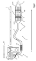
- a heat engine 1 of a motor vehicle is equipped with an exhaust line 2 to allow evacuation and treatment exhaust gases 3 produced by the engine 1 to the outside 4 of the motor vehicle.
- the exhaust line 2 has an end or upstream zone 11 in aeraulic communication with the heat engine 1, and an end or downstream zone 12 having an outward opening 4 of the vehicle.
- the concepts upstream and downstream are to be understood with regard to the direction of flow 6 of the exhaust gas 3 along the exhaust line 2, and more particularly inside a circulation duct 5 of the exhaust gases.
- exhaust 3 that includes the exhaust line 2.
- the conduit 5 channels the flow of exhaust gas 3 from the engine 1 to the outside 4 of the motor vehicle, that is to say in the open air.
- the duct 5 comprises from the heat engine 1 to the outside 4 of the motor vehicle a hot zone ZC followed by a cold zone ZF.
- hot zone ZC and cold zone ZF of the exhaust line 2 are to be considered with regard to a relative difference in temperatures of the exhaust gases 3 between said hot zone ZC and cold zone ZF of the exhaust line 2. 2 when exhausted from the upstream end 11 to the downstream end 12 of the exhaust line.
- the exhaust gases 3 are colder downstream than upstream of the exhaust line 2, due to a thermal inertia of the exhaust line 2 and its cooling provided by the outside air Surrounding the exhaust line 2.
- the hot zone ZC is located especially in the engine zone ZM of the vehicle and more particularly in a turbocharger T fitted to the engine 1.
- the cold zone ZF is located in the underbody C of the vehicle and is placed downstream of the hot zone ZC.
- This cold zone comprises an extension of the exhaust line 2 including its longitudinally median zone and its downstream zone. Although considered as a cold zone ZF, it will be understood that the longitudinally median zone and the downstream zone of the exhaust line 2 are at significantly different temperatures when the exhaust gases pass through them from the zone 3. hot ZC.
- the exhaust gases 3 contain harmful components that it is necessary to treat chemically and / or physically prior to their rejection outside the motor vehicle.
- Such an exhaust gas treatment constraint 3 is to be considered with regard to the regulations relating to the preservation of the environment, such as, for example, the EEC Directive 90 / C81 / 01 on the approval of a motor vehicle.
- Such a treatment of the exhaust gas 3 is obtained by the implementation of treatment and operating members of the exhaust line 2.
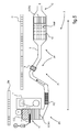
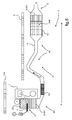
- such members comprise successively a catalyst of CO oxidation, an injector 7, incidentally a main mixer M, an upstream SCR element SCR1, incidentally a mixer M ', a particulate filter FAP and a SCR downstream element SCR2, which jointly and in combination provide a global chemical treatment and / or the physics of the exhaust 3.
- the end or downstream zone 12 of the exhaust line 2 is to be understood ending after a housing 10 housing at least the particulate filter FAP, which is placed in the cold zone ZF of the exhaust line. More particularly, the downstream end or zone 12 of the exhaust line 2 may be extended by the conduit 5 without departing from the rules that have been set forth. For example, such a downstream extension of the duct 5 is optionally provided with acoustic attenuation or screen members, or is provided to adapt the exhaust line 2 to a given vehicle architecture.
- the exhaust gases 3 contain nitrogen oxides (NOx, x being equal to 1 and / or 2) which are reduced prior to their discharge to the outside 4 of the motor vehicle.
- nitrogen oxides NOx
- x being equal to 1 and / or 2
- the duct 5 is equipped with the upstream SCR element SCR1 and the downstream SCR element SCR2. These elements SCR are successively placed in series and at a distance from one another on the conduit 5 while being separated from each other by an intermediate zone ZI of the exhaust line 2.
- the upstream SCR element SCR1 is located upstream of the downstream SCR element SCR2, the particle filter FAP being interposed between them.
- the SCR2 downstream SCR element constitutes a support for the reduction of nitrogen oxides (NOx) by ammonia from the reducing reagent which is optionally previously dissociated by the SCR1 upstream SCR element.
- the downstream SCR element SCR2 is traversed by exhaust gases which are colder than when they pass through the upstream SCR element SCR1.
- the SCR2 downstream SCR element is delayed with respect to that of the upstream SCR element SCR1, which makes it possible to optimize the chemical treatment of the gases in two successive stages and to dedicate the downstream SCR element SCR2 to the reduction of nitrogen oxides only.
- the downstream SCR element SCR2 is more particularly exploited under certain vehicle running conditions, such as on the highway or in case of acceleration for example, conditions for which the quantity of nitrogen oxides contained in the exhaust gases is increased.
- the injected reducing reagent is likely to be urea, a precursor of urea or the like.
- the upstream SCR element SCR1 provides a reaction of dissociation of the reducing reagent and reduction of nitrogen oxides contained in the exhaust gas 3 from the ammonia obtained.
- the reducing reagent is still likely to be ammonia directly injected into the exhaust line, in particular in the gaseous state, and the upstream SCR SCR1 and downstream SCR2 SCR elements provide a reduction reaction of nitrogen oxides by the ammonia previously injected.
- the ammonia is mixed with the exhaust gases to form a homogeneous mixture which flows to the particulate filter FAP and then to the upstream SCR element SCR2.
- the quality of the mixture obtained between the ammonia and the exhaust gas 3 makes it possible to preserve the particulate filter FAP from aging.
- the passage of the exhaust gases through the particulate filter FAP prior to their passage through the SCR downstream element SCR2 prevents fouling of this element and promote its ignition at low temperature of the order of 150 ° C.
- the downstream SCR element SCR2 is more particularly exploited under certain vehicle running conditions, such as on the highway or in case of acceleration for example, conditions for which the quantity of nitrogen oxides contained in the exhaust gases is increased.
- the dissociation of the global mass of the SCR element necessary for the operation of the SCRS system into at least two SCR elements respectively upstream and downstream makes it possible to confer on the multiple SCR elements of respective small volumes and to free up space in the ZM motor zone. of the vehicle.
- This released space is used to receive the oxidation catalyst CO which is advantageously placed in hot zone ZC of the exhaust line 2.
- the duct 5 comprises a flexible zone ZS which is advantageously interposed between the hot zone ZC and the cold zone ZF of the exhaust line 2. More particularly, this flexible zone ZS is formed in the longitudinally median zone of the exhaust line. 2, and more particularly downstream of the hot zone ZC which is located closest to the heat engine 1 in the situation of implantation of the exhaust line 2 on the vehicle.
- a flexible zone ZS provides the advantage of facilitating the extension and mounting of the exhaust line 2 on the vehicle, and in particular the extension of the exhaust line 2 between the engine zone ZM and the sub zone. -cash C of the vehicle.
- the provisions of the invention favoring obtaining a chemical treatment of the exhaust gas 3 by limiting the fouling of the exhaust line 2 despite the position in the cold zone ZF downstream of the particulate filter FAP, such a zone flexible ZS duct 5, deemed sensitive to fouling, is preserved and can be operated in a sustainable manner without affecting the operation of the exhaust line.
- the upstream SCR element SCR1 is housed in the housing 10 together with the particulate filter FAP and the downstream SCR element SCR2.
- the mixer M ' is housed in the housing 10, interposed between the upstream SCR element SCR1 and the particulate filter FAP, to promote the mixing of the ammonia with the exhaust gas 3 prior to their passage through the FAP particulate filter.
- the separation of the SCR element that comprises the SCRS system into two structurally distinct SCR elements separated by the intermediate zone ZI, provides a satisfactory operation of the SCRS system despite their situation in the cold zone ZF of the exhaust line 2, the downstream SCR element SCR2 being specifically dedicated to the reduction of nitrogen oxides and being preserved particles that comprise the exhaust gases that are previously sieved by the particulate filter.
- the outlet 7 'of the injector 7 is placed in a hot zone ZC, downstream close to the oxidation catalyst CO.
- the outlet 7 'of the injector 7 is placed in the cold zone ZF of the exhaust line 2, upstream of the housing 10 housing the particulate filter FAP interposed between the upstream SCR element SCR1 and the downstream SCR element SCR2 .
- the quality of the chemical treatment of the exhaust gases obtained makes it possible to place the outlet 7 'of the injector 7 in the C sub-box of the vehicle, in a location facilitating its implementation and freeing up space in the engine zone ZM deemed to be congested.
- the upstream SCR element SCR1 is placed in the hot zone ZC of the exhaust line, to promote its rapid initiation and to induce a mixing of the exhaust gas 3 mixed with the ammonia at the outlet of the element SCR1.
- This mixing is favored by a circulation of the exhaust gas 3 along the intermediate zone ZI, which extends between the hot zone ZC and cold zone ZF downstream of the exhaust line 2, in the underbody C of the vehicle. location of the exhaust line 2 on the vehicle.
- a mixer M ' may be interposed on the duct 5, in the intermediate zone ZI of the exhaust line 2, to reinforce the mix obtained.
- particulate filter FAP and the downstream SCR element SCR2 are capable of constituting a one-piece element performing the functions of filtering and reducing nitrogen oxides (NO x ).
- a unitary element may consist of a single ceramic part or the like impregnated with a reducing catalyst of nitrogen oxides.
- an auxiliary SCR element SCR3 may be interposed between the oxidation catalyst and the outlet 7 'of the injector 7.
- the processing and operating members of the exhaust line 2 which are disposed ZF cold zone are likely to be confined within a common housing, or to be distributed within several respective housings, separately or in combination.
Landscapes
- Engineering & Computer Science (AREA)
- Chemical & Material Sciences (AREA)
- Combustion & Propulsion (AREA)
- Mechanical Engineering (AREA)
- General Engineering & Computer Science (AREA)
- Chemical Kinetics & Catalysis (AREA)
- Health & Medical Sciences (AREA)
- Toxicology (AREA)
- Materials Engineering (AREA)
- Exhaust Gas After Treatment (AREA)
Applications Claiming Priority (1)
| Application Number | Priority Date | Filing Date | Title |
|---|---|---|---|
| FR1060519A FR2968711B1 (fr) | 2010-12-14 | 2010-12-14 | Ligne d'echappement pour vehicule automobile et methode d'epuration de gaz d'echappement produits par un moteur thermique equipant ce vehicule |
Publications (2)
| Publication Number | Publication Date |
|---|---|
| EP2466084A1 true EP2466084A1 (de) | 2012-06-20 |
| EP2466084B1 EP2466084B1 (de) | 2016-11-16 |
Family
ID=44259830
Family Applications (1)
| Application Number | Title | Priority Date | Filing Date |
|---|---|---|---|
| EP11190356.3A Not-in-force EP2466084B1 (de) | 2010-12-14 | 2011-11-23 | Abgassystem für ein Kraftfahrzeug |
Country Status (2)
| Country | Link |
|---|---|
| EP (1) | EP2466084B1 (de) |
| FR (1) | FR2968711B1 (de) |
Cited By (6)
| Publication number | Priority date | Publication date | Assignee | Title |
|---|---|---|---|---|
| WO2014060987A1 (en) * | 2012-10-18 | 2014-04-24 | Johnson Matthey Public Limited Company | Close-coupled scr system |
| EP2772302A1 (de) | 2013-02-27 | 2014-09-03 | Umicore AG & Co. KG | Hexagonaler Oxidationskatalysator |
| WO2017165184A1 (en) * | 2016-03-25 | 2017-09-28 | Caterpillar Inc. | Exhaust after-treatment system |
| US10823031B2 (en) | 2018-09-20 | 2020-11-03 | Faurecia Emissions Control Technologies, Usa, Llc | Method and apparatus for turbo bypass valve operation strategy for close coupled SCR |
| US10823030B2 (en) | 2018-06-11 | 2020-11-03 | Faurecia Emissions Control Technologies, Usa, Llc | Method and apparatus to control valve operation for close coupled SCR |
| JP2024150774A (ja) * | 2020-11-19 | 2024-10-23 | ヤンマーホールディングス株式会社 | ディーゼルエンジン |
Families Citing this family (1)
| Publication number | Priority date | Publication date | Assignee | Title |
|---|---|---|---|---|
| KR101777697B1 (ko) * | 2016-03-28 | 2017-09-12 | 희성촉매 주식회사 | 선택적 촉매 환원 반응용 촉매 부분 재생 장치 |
Citations (7)
| Publication number | Priority date | Publication date | Assignee | Title |
|---|---|---|---|---|
| EP0807749A2 (de) * | 1996-05-13 | 1997-11-19 | Scambia Industrial Developments Aktiengesellschaft | Abgasanlage für ein Kraftfahrzeug sowie Kraftfahrzeug |
| US6401455B1 (en) | 1997-07-24 | 2002-06-11 | Siemens Aktiengesellschaft | Exhaust emission control system for the exhaust gas of a diesel engine |
| DE10348799A1 (de) | 2002-11-21 | 2004-06-17 | Ford Global Technologies, LLC, Dearborn | Abgasnachbehandlungssysteme |
| US20070122317A1 (en) * | 2005-11-30 | 2007-05-31 | Driscoll James J | Multi-stage system for selective catalytic reduction |
| WO2008030314A1 (en) * | 2006-09-08 | 2008-03-13 | Caterpillar Inc. | Emissions reduction system |
| EP2042227A2 (de) | 2003-08-05 | 2009-04-01 | Engelhard Corporation | Emissionsbehandlungssystem und einen SCR-Filter verwendendes Verfahren |
| EP2148053A2 (de) * | 2008-07-25 | 2010-01-27 | Volkswagen AG | Katalysatoranordnung zur Reinigung eines Abgasstroms |
Family Cites Families (1)
| Publication number | Priority date | Publication date | Assignee | Title |
|---|---|---|---|---|
| US20090173063A1 (en) * | 2008-01-07 | 2009-07-09 | Boorse R Samuel | Mitigation of Particulates and NOx in Engine Exhaust |
-
2010
- 2010-12-14 FR FR1060519A patent/FR2968711B1/fr not_active Expired - Fee Related
-
2011
- 2011-11-23 EP EP11190356.3A patent/EP2466084B1/de not_active Not-in-force
Patent Citations (7)
| Publication number | Priority date | Publication date | Assignee | Title |
|---|---|---|---|---|
| EP0807749A2 (de) * | 1996-05-13 | 1997-11-19 | Scambia Industrial Developments Aktiengesellschaft | Abgasanlage für ein Kraftfahrzeug sowie Kraftfahrzeug |
| US6401455B1 (en) | 1997-07-24 | 2002-06-11 | Siemens Aktiengesellschaft | Exhaust emission control system for the exhaust gas of a diesel engine |
| DE10348799A1 (de) | 2002-11-21 | 2004-06-17 | Ford Global Technologies, LLC, Dearborn | Abgasnachbehandlungssysteme |
| EP2042227A2 (de) | 2003-08-05 | 2009-04-01 | Engelhard Corporation | Emissionsbehandlungssystem und einen SCR-Filter verwendendes Verfahren |
| US20070122317A1 (en) * | 2005-11-30 | 2007-05-31 | Driscoll James J | Multi-stage system for selective catalytic reduction |
| WO2008030314A1 (en) * | 2006-09-08 | 2008-03-13 | Caterpillar Inc. | Emissions reduction system |
| EP2148053A2 (de) * | 2008-07-25 | 2010-01-27 | Volkswagen AG | Katalysatoranordnung zur Reinigung eines Abgasstroms |
Cited By (16)
| Publication number | Priority date | Publication date | Assignee | Title |
|---|---|---|---|---|
| CN104903554B (zh) * | 2012-10-18 | 2019-04-16 | 庄信万丰股份有限公司 | 紧密耦合的scr系统 |
| RU2651917C2 (ru) * | 2012-10-18 | 2018-04-24 | Джонсон Мэтти Паблик Лимитед Компани | Близко размещенная система scr |
| WO2014060987A1 (en) * | 2012-10-18 | 2014-04-24 | Johnson Matthey Public Limited Company | Close-coupled scr system |
| GB2521576A (en) * | 2012-10-18 | 2015-06-24 | Johnson Matthey Plc | Close-coupled SCR system |
| CN104903554A (zh) * | 2012-10-18 | 2015-09-09 | 庄信万丰股份有限公司 | 紧密耦合的scr系统 |
| JP2016500786A (ja) * | 2012-10-18 | 2016-01-14 | ジョンソン、マッセイ、パブリック、リミテッド、カンパニーJohnson Matthey Publiclimited Company | 近位連結されたscrシステム |
| GB2521576B (en) * | 2012-10-18 | 2018-06-27 | Johnson Matthey Plc | Close-coupled SCR system |
| US9694322B2 (en) | 2013-02-27 | 2017-07-04 | Umicore Ag & Co. Kg | Hexagonal oxidation catalyst |
| EP2772302A1 (de) | 2013-02-27 | 2014-09-03 | Umicore AG & Co. KG | Hexagonaler Oxidationskatalysator |
| WO2014131708A1 (en) | 2013-02-27 | 2014-09-04 | Umicore Ag & Co. Kg | Hexagonal oxidation catalyst |
| US9879581B2 (en) | 2016-03-25 | 2018-01-30 | Caterpillar Inc. | After-treatment system |
| WO2017165184A1 (en) * | 2016-03-25 | 2017-09-28 | Caterpillar Inc. | Exhaust after-treatment system |
| CN108779694A (zh) * | 2016-03-25 | 2018-11-09 | 卡特彼勒公司 | 排气后处理系统 |
| US10823030B2 (en) | 2018-06-11 | 2020-11-03 | Faurecia Emissions Control Technologies, Usa, Llc | Method and apparatus to control valve operation for close coupled SCR |
| US10823031B2 (en) | 2018-09-20 | 2020-11-03 | Faurecia Emissions Control Technologies, Usa, Llc | Method and apparatus for turbo bypass valve operation strategy for close coupled SCR |
| JP2024150774A (ja) * | 2020-11-19 | 2024-10-23 | ヤンマーホールディングス株式会社 | ディーゼルエンジン |
Also Published As
| Publication number | Publication date |
|---|---|
| EP2466084B1 (de) | 2016-11-16 |
| FR2968711B1 (fr) | 2014-12-26 |
| FR2968711A1 (fr) | 2012-06-15 |
Similar Documents
| Publication | Publication Date | Title |
|---|---|---|
| EP2466084B1 (de) | Abgassystem für ein Kraftfahrzeug | |
| CN102844535B (zh) | 用于排出柴油机废气、具有氨解模块的设备 | |
| FR2964413A1 (fr) | Filtre a particules a trois revetements catalytiques | |
| EP1302232B1 (de) | Verfahren und Vorrichtung zur Reinigung eines Partikelfilters eines Autos | |
| FR2968713A1 (fr) | Ligne d'echappement pour vehicule automobile et methode d'epuration de gaz d'echappement produits par un moteur thermique equipant ce vehicule | |
| EP2529091B1 (de) | Abgasnachbehandlungsvorrichtung einer brennkraftmaschine | |
| WO2012172201A1 (fr) | Enveloppe coudee d'un ensemble de post-traitement des gaz d'echappement d'un moteur a combustion comportant deux demi-coquilles | |
| FR2971546A1 (fr) | Ligne d'echappement pour moteur a combustion, dotee d'un organe de guidage d'un melange entre des gaz d'echappement et un agent reducteur | |
| EP3153677B1 (de) | Vorrichtung zur nachbehandlung von abgasen eines verbrennungsmotors | |
| FR2968709A1 (fr) | Methode d'epuration des gaz d'echappement produits par un moteur thermique equipant un vehicule automobile | |
| FR2968710A1 (fr) | Ligne d'echappement pour vehicule automobile et methode d'epuration de gaz d'echappement produits par un moteur thermique equipant ce vehicule. | |
| EP2678536B1 (de) | Kraftfahrzeug beinhaltend eine abgasanlage wobei die akustische vorrichtung vor dem hinteradantrieb angeordnet ist | |
| EP3149300B1 (de) | Abgasnachbehandlungseinrichtung für eine brennkraftmaschine | |
| FR2968708A1 (fr) | Ligne d'echappement pour vehicule automobile et methode d'epuration de gaz d'echappement produits par un moteur thermique equipant ce vehicule | |
| EP2411648B1 (de) | Verfahren zur überwachung von schadstoffemissionen eines verbrennungsmotors | |
| FR2968712A1 (fr) | Methode d'epuration des gaz d'echappement produits par un moteur thermique equipant un vehicule automobile | |
| FR3081921A1 (fr) | Ligne d’echappement de moteur thermique comprenant un element de chauffage amont | |
| FR2940921A1 (fr) | Dispositif de traitement des gaz d'echappement d'un moteur | |
| EP2496801A1 (de) | Vorrichtung zur behandlung von abgasen aus einem fahrzeug mit einer wärmekraftmaschine | |
| EP2708709B1 (de) | Abgasanlage mit einer Vorrichtung zur Aufbereitung von umweltschädlichen Emissionen eines Wärmekraftmotors durch katalytische Reduktion, unabhängig von der an Bord befindlichen Reduktionsvorrichtung | |
| FR2955612A1 (fr) | Dispositif de post-traitement des gaz d'echappement d'un moteur a combustion | |
| EP3311013A1 (de) | Optimiertes system zur verminderung der verunreinigung von abgasen | |
| FR3019062A1 (fr) | Ensemble de depollution des gaz de combustion | |
| EP3114330A1 (de) | Dreiwegkatalysator | |
| FR2971005A1 (fr) | Ligne d'echappement pour moteur a combustion interne |
Legal Events
| Date | Code | Title | Description |
|---|---|---|---|
| PUAI | Public reference made under article 153(3) epc to a published international application that has entered the european phase |
Free format text: ORIGINAL CODE: 0009012 |
|
| AK | Designated contracting states |
Kind code of ref document: A1 Designated state(s): AL AT BE BG CH CY CZ DE DK EE ES FI FR GB GR HR HU IE IS IT LI LT LU LV MC MK MT NL NO PL PT RO RS SE SI SK SM TR |
|
| AX | Request for extension of the european patent |
Extension state: BA ME |
|
| 17P | Request for examination filed |
Effective date: 20121129 |
|
| 17Q | First examination report despatched |
Effective date: 20150206 |
|
| GRAP | Despatch of communication of intention to grant a patent |
Free format text: ORIGINAL CODE: EPIDOSNIGR1 |
|
| RIC1 | Information provided on ipc code assigned before grant |
Ipc: F01N 13/00 20100101ALI20160519BHEP Ipc: F01N 3/035 20060101AFI20160519BHEP Ipc: F01N 13/18 20100101ALI20160519BHEP Ipc: F01N 3/20 20060101ALI20160519BHEP Ipc: F01N 3/28 20060101ALI20160519BHEP Ipc: F01N 3/10 20060101ALI20160519BHEP |
|
| INTG | Intention to grant announced |
Effective date: 20160616 |
|
| GRAS | Grant fee paid |
Free format text: ORIGINAL CODE: EPIDOSNIGR3 |
|
| GRAA | (expected) grant |
Free format text: ORIGINAL CODE: 0009210 |
|
| AK | Designated contracting states |
Kind code of ref document: B1 Designated state(s): AL AT BE BG CH CY CZ DE DK EE ES FI FR GB GR HR HU IE IS IT LI LT LU LV MC MK MT NL NO PL PT RO RS SE SI SK SM TR |
|
| REG | Reference to a national code |
Ref country code: GB Ref legal event code: FG4D Free format text: NOT ENGLISH |
|
| REG | Reference to a national code |
Ref country code: CH Ref legal event code: EP |
|
| REG | Reference to a national code |
Ref country code: IE Ref legal event code: FG4D Free format text: LANGUAGE OF EP DOCUMENT: FRENCH |
|
| REG | Reference to a national code |
Ref country code: AT Ref legal event code: REF Ref document number: 846168 Country of ref document: AT Kind code of ref document: T Effective date: 20161215 |
|
| REG | Reference to a national code |
Ref country code: FR Ref legal event code: PLFP Year of fee payment: 6 |
|
| REG | Reference to a national code |
Ref country code: DE Ref legal event code: R096 Ref document number: 602011032397 Country of ref document: DE |
|
| REG | Reference to a national code |
Ref country code: DE Ref legal event code: R096 Ref document number: 602011032397 Country of ref document: DE |
|
| REG | Reference to a national code |
Ref country code: DE Ref legal event code: R084 Ref document number: 602011032397 Country of ref document: DE |
|
| PG25 | Lapsed in a contracting state [announced via postgrant information from national office to epo] |
Ref country code: LV Free format text: LAPSE BECAUSE OF FAILURE TO SUBMIT A TRANSLATION OF THE DESCRIPTION OR TO PAY THE FEE WITHIN THE PRESCRIBED TIME-LIMIT Effective date: 20161116 |
|
| REG | Reference to a national code |
Ref country code: NL Ref legal event code: MP Effective date: 20161116 |
|
| REG | Reference to a national code |
Ref country code: LT Ref legal event code: MG4D |
|
| REG | Reference to a national code |
Ref country code: AT Ref legal event code: MK05 Ref document number: 846168 Country of ref document: AT Kind code of ref document: T Effective date: 20161116 |
|
| PG25 | Lapsed in a contracting state [announced via postgrant information from national office to epo] |
Ref country code: GR Free format text: LAPSE BECAUSE OF FAILURE TO SUBMIT A TRANSLATION OF THE DESCRIPTION OR TO PAY THE FEE WITHIN THE PRESCRIBED TIME-LIMIT Effective date: 20170217 Ref country code: SE Free format text: LAPSE BECAUSE OF FAILURE TO SUBMIT A TRANSLATION OF THE DESCRIPTION OR TO PAY THE FEE WITHIN THE PRESCRIBED TIME-LIMIT Effective date: 20161116 Ref country code: NO Free format text: LAPSE BECAUSE OF FAILURE TO SUBMIT A TRANSLATION OF THE DESCRIPTION OR TO PAY THE FEE WITHIN THE PRESCRIBED TIME-LIMIT Effective date: 20170216 Ref country code: LT Free format text: LAPSE BECAUSE OF FAILURE TO SUBMIT A TRANSLATION OF THE DESCRIPTION OR TO PAY THE FEE WITHIN THE PRESCRIBED TIME-LIMIT Effective date: 20161116 Ref country code: NL Free format text: LAPSE BECAUSE OF FAILURE TO SUBMIT A TRANSLATION OF THE DESCRIPTION OR TO PAY THE FEE WITHIN THE PRESCRIBED TIME-LIMIT Effective date: 20161116 |
|
| PG25 | Lapsed in a contracting state [announced via postgrant information from national office to epo] |
Ref country code: ES Free format text: LAPSE BECAUSE OF FAILURE TO SUBMIT A TRANSLATION OF THE DESCRIPTION OR TO PAY THE FEE WITHIN THE PRESCRIBED TIME-LIMIT Effective date: 20161116 Ref country code: PT Free format text: LAPSE BECAUSE OF FAILURE TO SUBMIT A TRANSLATION OF THE DESCRIPTION OR TO PAY THE FEE WITHIN THE PRESCRIBED TIME-LIMIT Effective date: 20170316 Ref country code: RS Free format text: LAPSE BECAUSE OF FAILURE TO SUBMIT A TRANSLATION OF THE DESCRIPTION OR TO PAY THE FEE WITHIN THE PRESCRIBED TIME-LIMIT Effective date: 20161116 Ref country code: BE Free format text: LAPSE BECAUSE OF NON-PAYMENT OF DUE FEES Effective date: 20161130 Ref country code: FI Free format text: LAPSE BECAUSE OF FAILURE TO SUBMIT A TRANSLATION OF THE DESCRIPTION OR TO PAY THE FEE WITHIN THE PRESCRIBED TIME-LIMIT Effective date: 20161116 Ref country code: AT Free format text: LAPSE BECAUSE OF FAILURE TO SUBMIT A TRANSLATION OF THE DESCRIPTION OR TO PAY THE FEE WITHIN THE PRESCRIBED TIME-LIMIT Effective date: 20161116 Ref country code: PL Free format text: LAPSE BECAUSE OF FAILURE TO SUBMIT A TRANSLATION OF THE DESCRIPTION OR TO PAY THE FEE WITHIN THE PRESCRIBED TIME-LIMIT Effective date: 20161116 Ref country code: HR Free format text: LAPSE BECAUSE OF FAILURE TO SUBMIT A TRANSLATION OF THE DESCRIPTION OR TO PAY THE FEE WITHIN THE PRESCRIBED TIME-LIMIT Effective date: 20161116 |
|
| REG | Reference to a national code |
Ref country code: CH Ref legal event code: PL |
|
| REG | Reference to a national code |
Ref country code: GB Ref legal event code: 746 Effective date: 20170703 |
|
| PG25 | Lapsed in a contracting state [announced via postgrant information from national office to epo] |
Ref country code: CZ Free format text: LAPSE BECAUSE OF FAILURE TO SUBMIT A TRANSLATION OF THE DESCRIPTION OR TO PAY THE FEE WITHIN THE PRESCRIBED TIME-LIMIT Effective date: 20161116 Ref country code: RO Free format text: LAPSE BECAUSE OF FAILURE TO SUBMIT A TRANSLATION OF THE DESCRIPTION OR TO PAY THE FEE WITHIN THE PRESCRIBED TIME-LIMIT Effective date: 20161116 Ref country code: CH Free format text: LAPSE BECAUSE OF NON-PAYMENT OF DUE FEES Effective date: 20161130 Ref country code: EE Free format text: LAPSE BECAUSE OF FAILURE TO SUBMIT A TRANSLATION OF THE DESCRIPTION OR TO PAY THE FEE WITHIN THE PRESCRIBED TIME-LIMIT Effective date: 20161116 Ref country code: LI Free format text: LAPSE BECAUSE OF NON-PAYMENT OF DUE FEES Effective date: 20161130 Ref country code: SK Free format text: LAPSE BECAUSE OF FAILURE TO SUBMIT A TRANSLATION OF THE DESCRIPTION OR TO PAY THE FEE WITHIN THE PRESCRIBED TIME-LIMIT Effective date: 20161116 Ref country code: DK Free format text: LAPSE BECAUSE OF FAILURE TO SUBMIT A TRANSLATION OF THE DESCRIPTION OR TO PAY THE FEE WITHIN THE PRESCRIBED TIME-LIMIT Effective date: 20161116 |
|
| REG | Reference to a national code |
Ref country code: DE Ref legal event code: R097 Ref document number: 602011032397 Country of ref document: DE |
|
| REG | Reference to a national code |
Ref country code: IE Ref legal event code: MM4A |
|
| PG25 | Lapsed in a contracting state [announced via postgrant information from national office to epo] |
Ref country code: BG Free format text: LAPSE BECAUSE OF FAILURE TO SUBMIT A TRANSLATION OF THE DESCRIPTION OR TO PAY THE FEE WITHIN THE PRESCRIBED TIME-LIMIT Effective date: 20170216 Ref country code: IT Free format text: LAPSE BECAUSE OF FAILURE TO SUBMIT A TRANSLATION OF THE DESCRIPTION OR TO PAY THE FEE WITHIN THE PRESCRIBED TIME-LIMIT Effective date: 20161116 Ref country code: SM Free format text: LAPSE BECAUSE OF FAILURE TO SUBMIT A TRANSLATION OF THE DESCRIPTION OR TO PAY THE FEE WITHIN THE PRESCRIBED TIME-LIMIT Effective date: 20161116 |
|
| PLBE | No opposition filed within time limit |
Free format text: ORIGINAL CODE: 0009261 |
|
| STAA | Information on the status of an ep patent application or granted ep patent |
Free format text: STATUS: NO OPPOSITION FILED WITHIN TIME LIMIT |
|
| PG25 | Lapsed in a contracting state [announced via postgrant information from national office to epo] |
Ref country code: LU Free format text: LAPSE BECAUSE OF NON-PAYMENT OF DUE FEES Effective date: 20161130 Ref country code: MC Free format text: LAPSE BECAUSE OF FAILURE TO SUBMIT A TRANSLATION OF THE DESCRIPTION OR TO PAY THE FEE WITHIN THE PRESCRIBED TIME-LIMIT Effective date: 20161116 |
|
| REG | Reference to a national code |
Ref country code: FR Ref legal event code: PLFP Year of fee payment: 7 |
|
| 26N | No opposition filed |
Effective date: 20170817 |
|
| PG25 | Lapsed in a contracting state [announced via postgrant information from national office to epo] |
Ref country code: IE Free format text: LAPSE BECAUSE OF NON-PAYMENT OF DUE FEES Effective date: 20161123 Ref country code: SI Free format text: LAPSE BECAUSE OF FAILURE TO SUBMIT A TRANSLATION OF THE DESCRIPTION OR TO PAY THE FEE WITHIN THE PRESCRIBED TIME-LIMIT Effective date: 20161116 |
|
| REG | Reference to a national code |
Ref country code: BE Ref legal event code: MM Effective date: 20161130 |
|
| PG25 | Lapsed in a contracting state [announced via postgrant information from national office to epo] |
Ref country code: HU Free format text: LAPSE BECAUSE OF FAILURE TO SUBMIT A TRANSLATION OF THE DESCRIPTION OR TO PAY THE FEE WITHIN THE PRESCRIBED TIME-LIMIT; INVALID AB INITIO Effective date: 20111123 Ref country code: CY Free format text: LAPSE BECAUSE OF FAILURE TO SUBMIT A TRANSLATION OF THE DESCRIPTION OR TO PAY THE FEE WITHIN THE PRESCRIBED TIME-LIMIT Effective date: 20161116 |
|
| PG25 | Lapsed in a contracting state [announced via postgrant information from national office to epo] |
Ref country code: MK Free format text: LAPSE BECAUSE OF FAILURE TO SUBMIT A TRANSLATION OF THE DESCRIPTION OR TO PAY THE FEE WITHIN THE PRESCRIBED TIME-LIMIT Effective date: 20161116 Ref country code: IS Free format text: LAPSE BECAUSE OF FAILURE TO SUBMIT A TRANSLATION OF THE DESCRIPTION OR TO PAY THE FEE WITHIN THE PRESCRIBED TIME-LIMIT Effective date: 20161116 Ref country code: TR Free format text: LAPSE BECAUSE OF FAILURE TO SUBMIT A TRANSLATION OF THE DESCRIPTION OR TO PAY THE FEE WITHIN THE PRESCRIBED TIME-LIMIT Effective date: 20161116 |
|
| REG | Reference to a national code |
Ref country code: FR Ref legal event code: CA Effective date: 20180312 Ref country code: FR Ref legal event code: CD Owner name: PEUGEOT CITROEN AUTOMOBILES SA, FR Effective date: 20180312 |
|
| PG25 | Lapsed in a contracting state [announced via postgrant information from national office to epo] |
Ref country code: MT Free format text: LAPSE BECAUSE OF FAILURE TO SUBMIT A TRANSLATION OF THE DESCRIPTION OR TO PAY THE FEE WITHIN THE PRESCRIBED TIME-LIMIT Effective date: 20161116 |
|
| REG | Reference to a national code |
Ref country code: FR Ref legal event code: PLFP Year of fee payment: 8 |
|
| PG25 | Lapsed in a contracting state [announced via postgrant information from national office to epo] |
Ref country code: AL Free format text: LAPSE BECAUSE OF FAILURE TO SUBMIT A TRANSLATION OF THE DESCRIPTION OR TO PAY THE FEE WITHIN THE PRESCRIBED TIME-LIMIT Effective date: 20161116 |
|
| PGFP | Annual fee paid to national office [announced via postgrant information from national office to epo] |
Ref country code: GB Payment date: 20221021 Year of fee payment: 12 Ref country code: DE Payment date: 20220616 Year of fee payment: 12 |
|
| PGFP | Annual fee paid to national office [announced via postgrant information from national office to epo] |
Ref country code: FR Payment date: 20231020 Year of fee payment: 13 |
|
| REG | Reference to a national code |
Ref country code: DE Ref legal event code: R119 Ref document number: 602011032397 Country of ref document: DE |
|
| GBPC | Gb: european patent ceased through non-payment of renewal fee |
Effective date: 20231123 |
|
| PG25 | Lapsed in a contracting state [announced via postgrant information from national office to epo] |
Ref country code: DE Free format text: LAPSE BECAUSE OF NON-PAYMENT OF DUE FEES Effective date: 20240601 |
|
| PG25 | Lapsed in a contracting state [announced via postgrant information from national office to epo] |
Ref country code: GB Free format text: LAPSE BECAUSE OF NON-PAYMENT OF DUE FEES Effective date: 20231123 |
|
| PG25 | Lapsed in a contracting state [announced via postgrant information from national office to epo] |
Ref country code: GB Free format text: LAPSE BECAUSE OF NON-PAYMENT OF DUE FEES Effective date: 20231123 Ref country code: DE Free format text: LAPSE BECAUSE OF NON-PAYMENT OF DUE FEES Effective date: 20240601 |
|
| PG25 | Lapsed in a contracting state [announced via postgrant information from national office to epo] |
Ref country code: FR Free format text: LAPSE BECAUSE OF NON-PAYMENT OF DUE FEES Effective date: 20241130 |