EP2465802A2 - Yarn winding device - Google Patents
Yarn winding device Download PDFInfo
- Publication number
- EP2465802A2 EP2465802A2 EP11189514A EP11189514A EP2465802A2 EP 2465802 A2 EP2465802 A2 EP 2465802A2 EP 11189514 A EP11189514 A EP 11189514A EP 11189514 A EP11189514 A EP 11189514A EP 2465802 A2 EP2465802 A2 EP 2465802A2
- Authority
- EP
- European Patent Office
- Prior art keywords
- yarn
- guide
- traverse
- bobbin
- unit
- Prior art date
- Legal status (The legal status is an assumption and is not a legal conclusion. Google has not performed a legal analysis and makes no representation as to the accuracy of the status listed.)
- Granted
Links
Images


Classifications
-
- B—PERFORMING OPERATIONS; TRANSPORTING
- B65—CONVEYING; PACKING; STORING; HANDLING THIN OR FILAMENTARY MATERIAL
- B65H—HANDLING THIN OR FILAMENTARY MATERIAL, e.g. SHEETS, WEBS, CABLES
- B65H54/00—Winding, coiling, or depositing filamentary material
- B65H54/02—Winding and traversing material on to reels, bobbins, tubes, or like package cores or formers
- B65H54/38—Arrangements for preventing ribbon winding ; Arrangements for preventing irregular edge forming, e.g. edge raising or yarn falling from the edge
- B65H54/388—Preventing the yarn from falling off the edge of the package
-
- B—PERFORMING OPERATIONS; TRANSPORTING
- B65—CONVEYING; PACKING; STORING; HANDLING THIN OR FILAMENTARY MATERIAL
- B65H—HANDLING THIN OR FILAMENTARY MATERIAL, e.g. SHEETS, WEBS, CABLES
- B65H59/00—Adjusting or controlling tension in filamentary material, e.g. for preventing snarling; Applications of tension indicators
- B65H59/10—Adjusting or controlling tension in filamentary material, e.g. for preventing snarling; Applications of tension indicators by devices acting on running material and not associated with supply or take-up devices
- B65H59/36—Floating elements compensating for irregularities in supply or take-up of material
-
- B—PERFORMING OPERATIONS; TRANSPORTING
- B65—CONVEYING; PACKING; STORING; HANDLING THIN OR FILAMENTARY MATERIAL
- B65H—HANDLING THIN OR FILAMENTARY MATERIAL, e.g. SHEETS, WEBS, CABLES
- B65H54/00—Winding, coiling, or depositing filamentary material
- B65H54/02—Winding and traversing material on to reels, bobbins, tubes, or like package cores or formers
- B65H54/04—Winding and traversing material on to reels, bobbins, tubes, or like package cores or formers for making packages with closely-wound convolutions
-
- B—PERFORMING OPERATIONS; TRANSPORTING
- B65—CONVEYING; PACKING; STORING; HANDLING THIN OR FILAMENTARY MATERIAL
- B65H—HANDLING THIN OR FILAMENTARY MATERIAL, e.g. SHEETS, WEBS, CABLES
- B65H54/00—Winding, coiling, or depositing filamentary material
- B65H54/02—Winding and traversing material on to reels, bobbins, tubes, or like package cores or formers
- B65H54/28—Traversing devices; Package-shaping arrangements
- B65H54/30—Traversing devices; Package-shaping arrangements with thread guides reciprocating or oscillating with fixed stroke
-
- B—PERFORMING OPERATIONS; TRANSPORTING
- B65—CONVEYING; PACKING; STORING; HANDLING THIN OR FILAMENTARY MATERIAL
- B65H—HANDLING THIN OR FILAMENTARY MATERIAL, e.g. SHEETS, WEBS, CABLES
- B65H59/00—Adjusting or controlling tension in filamentary material, e.g. for preventing snarling; Applications of tension indicators
-
- B—PERFORMING OPERATIONS; TRANSPORTING
- B65—CONVEYING; PACKING; STORING; HANDLING THIN OR FILAMENTARY MATERIAL
- B65H—HANDLING THIN OR FILAMENTARY MATERIAL, e.g. SHEETS, WEBS, CABLES
- B65H67/00—Replacing or removing cores, receptacles, or completed packages at paying-out, winding, or depositing stations
- B65H67/04—Arrangements for removing completed take-up packages and or replacing by cores, formers, or empty receptacles at winding or depositing stations; Transferring material between adjacent full and empty take-up elements
- B65H67/044—Continuous winding apparatus for winding on two or more winding heads in succession
- B65H67/048—Continuous winding apparatus for winding on two or more winding heads in succession having winding heads arranged on rotary capstan head
-
- B—PERFORMING OPERATIONS; TRANSPORTING
- B65—CONVEYING; PACKING; STORING; HANDLING THIN OR FILAMENTARY MATERIAL
- B65H—HANDLING THIN OR FILAMENTARY MATERIAL, e.g. SHEETS, WEBS, CABLES
- B65H2701/00—Handled material; Storage means
- B65H2701/30—Handled filamentary material
- B65H2701/31—Textiles threads or artificial strands of filaments
- B65H2701/313—Synthetic polymer threads
- B65H2701/3132—Synthetic polymer threads extruded from spinnerets
Definitions
- the present invention relates to a yarn winding device which traverses yarns by a traverse unit and wind them onto a bobbin so as to form a package.
- a known yarn winding device has a traverse unit traversing yarns in the axial directions of bobbins and forms a package by winding yarns onto a bobbin while traversing the yarns.
- various methods of traversing yarns by the traverse unit of the yarn winding device have been known.
- Patent Document 1 Japanese Unexamined Patent Publication No.
- a cam drum traverse unit which is arranged to include a cam drum which is provided to be in parallel to the shaft of a bobbin and has a helical cam groove on the circumference and a traverse guide which reciprocates in the axial directions of the bobbin along the cam groove in response to the rotation of the cam drum.
- the traverse guide of this cam drum traverse unit moves so as to traverse yarns in the axial directions of the bobbin while sandwiching and binding the running yarns in the axial directions.
- Patent Document 2 Japanese Examined Patent Publication No. 3985/1979 ( Tokukosho 54-3985 ) ( Fig. 4 ) recites a rotating-blade-type traverse unit which has two blade-shaped traverse guides which are superposed onto each other and rotate in reverse directions.
- this traverse unit after a yarn is moved on one side in the axial directions of the bobbin by one traverse guide, the yarn is passed to the other traverse guide at the end point (i.e. an edge of the winding target range on the bobbin), and the yarn is moved to the other side in the axial directions of the bobbin by the other traverse guide.
- This Patent Document 2 aims at reducing the yarn accumulation (so-called saddle bag) at the end portions of the package.
- the technology recited in the document utilizes the yarn returning effect at the respective traversal ends, in a traverse unit which winds yarns such that a yarn guided by a traverse guide to a traversal end comes off from the traverse guide and is then engaged with another traverse guide and guided in a reverse direction.
- position regulation guides are provided at the traversal ends to arrange the speed of the yarn returning from a traversal end to be higher than the speed of the movement of the traverse guide, with the result that the yarn accumulation at the traversal ends is alleviated.
- a yarn Y is traversed while changing its form in the order of (3) ⁇ (2) ⁇ (1) ⁇ (2) ⁇ (3).
- a traverse guide 80 goes beyond the winding target range of a bobbin 81 and is reversed, the linear distance between the contact point Al of the running yarn Y with the traverse guide 80 and the contact point A2 of the running yarn Y with the bobbin 81 is short.
- the speed of winding onto the bobbin 81 i.e. the speed of supplying the yarn
- An object of the present invention is therefore to restrain the occurrence of yarn stitching by eliminating the slack in a yarn, which occurs between a bobbin and a traverse guide when the traverse guide is reversed.
- a yarn winding device of the present invention includes: a winding unit which winds a yarn onto a bobbin; a traverse unit which reciprocally moves the running yarn in axial directions of the bobbin; and a slack removal unit which removes the slack in the yarn running between the traverse guide and the bobbin, when the traverse guide is reversed.
- the yarn winding device of the present invention since the slack in a yarn running between the traverse guide and the bobbin is removed when the traverse guide is reversed, a yarn having a stable yarn form is wound at an edge of the winding target range of the bobbin, with the result that the occurrence of the yarn stitching is restrained.
- the yarn winding device is preferably arranged so that the slack removal unit is provided on a side upstream of the traverse guide in a direction in which the yarn runs, and is a resistance imparting unit which contacts the running yarn to impart, to the yarn, running resistance against the direction in which the yarn runs, when the traverse guide is reversed.
- the slack in the yarn is easily removed only by imparting running resistance against the running direction of the yarn when the traverse guide is reversed, as the tension on the yarn is increased on the side downstream of the resistance imparting unit.
- the yarn winding device preferably further includes: a fulcrum guide which is fixedly provided on the side upstream of the traverse guide in the direction in which the yarn runs; and a contact guide which is provided between the fulcrum guide and the traverse guide and functions as the resistance imparting unit, the contact guide externally contacting, in the axial directions of the bobbin, the yarn between the fulcrum guide and the traverse guide, on a line connecting the fulcrum guide with the traverse guide when the traverse guide reaches an edge of a winding target range of the bobbin.
- the yarn running between the traverse guide and the bobbin is maximally slackened when the direct distance between the contact point of the running yarn with the traverse guide and the contact point of the running yarn with the bobbin becomes the shortest, i.e., when the traverse guide reaches the edge of the winding target range of the bobbin.
- the contact guide contacts the yarn running between the fulcrum guide and the bobbin, on the line L2 (see Fig. 3 ) connecting the fulcrum guide with the traverse guide at the aforesaid position.
- the contact guide gets closer to the traversal center and away from the line L2, the angle of the yarn contacting and bended by the contact guide increases, and hence the damage onto the running yarn between the traverse guide and the bobbin becomes serious in comparison with the effect of removing the slack in the yarn.
- the contact guide contacts the yarn running between the fulcrum guide and the bobbin on the line L2, it is possible to effectively remove the slack in the yarn running between the traverse guide and the bobbin.
- the yarn winding device preferably further includes: a position change unit which changes a position of the contact guide in the axial directions of the bobbin; and a position control unit which controls the position change unit.
- the yarn winding device is preferably arranged so that the traverse unit is able to change a reversal position where the traverse guide is reversed, and the position control unit controls the position change unit so as to move the contact guide in accordance with a direction in which the reversal position of the traverse guide is changed, while the yarn is being wound onto the bobbin.
- the end faces of the package may be arranged to tilt axially outward.
- the reversal position of the traverse guide moves inward as the amount of wound yarns increases.
- the contact guide is moved inward. With this, the contact guide surely contacts the running yarn when the traverse guide is reversed, with the result that the yarn stitching is more effectively restrained.
- the yarn winding device preferably further includes: a winding control unit which controls a rotation speed of the bobbin rotated by the winding unit, the winding control unit controlling the winding unit so as to function as the slack removal unit which removes the slack in the yarn running between the traverse guide and the bobbin, by temporarily increasing the rotation speed of the bobbin when the traverse guide is reversed.
- the slack in the yarn running between the traverse guide and the bobbin is removed with less decrease in the quality of the yarn, as compared to the arrangement in which the slack is removed by imparting running resistance to the yarn.
- the yarn having the desired shape is wound at the edge of the winding target range on the bobbin, the occurrence of the yarn stitching is restrained.
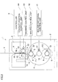
- Fig. 1 is a profile of a yarn winding device according to First Embodiment of the present invention.
- Fig. 2 is a front elevation of the yarn winding device.
- a yarn winding device 1 successively receives a plurality of yarns Y from an unillustrated spinning machine provided above.
- the yarn winding device 1 is arranged to form a plurality of packages 10 by winding the yarns Y supplied from the spinning machine onto a plurality of bobbins 9.
- the yarn winding device 1 includes components such as a main body frame 2, an elevation frame 3 provided to the main body frame 2 to be vertically movable, a disc-shaped turret 4 rotatably provided to the main body frame 2, two bobbin holders 5 (winding units) each of which is supported by the turret 4 at one end and to which a plurality of bobbins 9 are attached, a traverse unit 6 which traverses the yarn Y which is to be wound onto the bobbin 9, a contact roller 7 which is able to contact the bobbins 9 attached to the bobbin holders 5, and a controller 8 which controls the overall operation by controlling the components.
- components such as a main body frame 2, an elevation frame 3 provided to the main body frame 2 to be vertically movable, a disc-shaped turret 4 rotatably provided to the main body frame 2, two bobbin holders 5 (winding units) each of which is supported by the turret 4 at one end and to which a plurality of bobbins 9 are
- the turret 4 is disc-shaped and is rotatably attached to the main body frame 2. At two positions which are symmetrical with respect to a shaft 4a which is the rotation center of the turret 4, ends of the two bobbin holders 5 are connected, respectively.
- the two bobbin holders 5 are rotatably protrude from the turret 4.
- the two bobbin holders 5 are arranged to rotate together with the turret 4.
- To each of the two bobbin holders 5, a plurality of bobbins 9 are attached in series in the axial directions of the bobbin holder 5.
- the turret 4 is rotated about the shaft 4a by a rotation motor 31. As the turret 4 is rotated, each of the two bobbin holders 5 moves between a winding position P1 at which the bobbin holder 5 contacts the contact roller 7 and yarns Y are wound onto the bobbins 9 and a standby position P2 which is below the winding position P1 and is point-symmetrical with the winding position P1 with respect to the shaft 4a of the turret 4.
- this bobbin holder 5 at the winding position P1 is switched to the standby position P2 whereas the bobbin holder 5 at the winding position P2 is switched to the winding position P1.
- Each of the two bobbin holders 5 supported by the turret 4 is rotated by the rotation motor 32.
- the bobbin holder 5 at the winding position P1 is rotated, the yarns Y are wound onto the bobbins 9 attached to this bobbin holder 5.
- the elevation frame 3 is a long frame extending in the axial directions of the bobbin holder 5, and supported by the main body frame 2 at its base end in the longitudinal direction.
- the elevation frame 3 is connected to a rod of an unillustrated cylinder fixed to the main body frame 2, and is vertically moved (i.e. moved in the direction away from the bobbin holder 5) with respect to the main body frame 2, as the cylinder is driven.
- the traverse unit 6 is provided on the elevation frame 3 and includes components such as fulcrum guides 19, a traverse cam 20, traverse guides 21, and a traverse motor 33.
- the fulcrum guides 19 are provided around the upper end of the elevation frame 3.
- the yarns Y supplied from the spinning machine are placed onto these fulcrum guides 19, and they function as the traversal fulcrums of the yarns Y.
- the traverse cam 20 is provided to be in parallel to the bobbin holder 5 and is rotatably supported by the elevation frame 3.
- the traverse cam 20 has a helical cam groove on its circumference, and is rotated by the traverse motor 33.
- the traverse guides 21 move along the cam groove as the traverse cam 20 is rotated, and reciprocate in the axial directions of the traverse cam 20 (bobbin holder 5).
- Each traverse guide 21 is arranged to sandwich a running yarn Y by two guide portions 21a in the axial directions of the bobbin holder 5.
- the traverse guide 21 guides the yarn Y running through the fulcrum guide 19 to the contact roller 7 while traversing, by using the fulcrum guide 19 as a fulcrum, the yarn Y in the axial directions (traversing directions) of the bobbin holder 5.
- yarn stitching restraining guides 50 are provided to be able to contact the yarns Y traversed by the traverse guide 21.
- Each yarn stitching restraining guide 50 is connected to the rod of the cylinder 34 fixed to the elevation frame 3. As the cylinder 34 is driven, the yarn stitching restraining guide 50 moves in the traversing directions with respect to the elevation frame 3.
- This yarn stitching restraining guide 50 will be detailed later. It is noted that, in First Embodiment, the yarn stitching restraining guides 50 may be fixed and immovable. On the other hand, the yarn stitching restraining guide 50 must be arranged to be movable in later-described Second Embodiment.
- the elevation frame 3 is connected to a supporting frame 11, and two supporting portions 11a rotatably supporting the contact roller 7 are provided at the respective longitudinal end portions of the supporting frame 11.
- the supporting frame 11 is long along the length of the elevation frame 3. Further, the supporting frame 11 is connected to the guide plate 12 at the longitudinal end portions of the supporting frame 11, and is arranged to be vertically movable with respect to the guide plate 12 (elevation frame 3) .
- the contact roller 7 is supported by the two supporting portions 11a of the supporting frame 11 to be in parallel to the bobbin holder 5. This contact roller 7 is arranged to be able to contact the outer circumferences of the bobbins 9 attached to the bobbin holder 5 at the winding position P1 or the packages 10 formed by winding the yarns Y onto the bobbins 9.
- the contact roller 7 is rotated by the rotation of the bobbin holder 5 while applying a predetermined contact pressure onto the packages 10, so as to adjust the shape of each package 10.
- the supporting frame 11 and the contact roller 7 are guided by the guide plate 12 to change their relative positions with respect to the elevation frame 3 in the direction to approach the bobbins 9 at the winding position P1 (i.e. downward direction) or in the direction away from these bobbins 9 (i.e. upward direction).
- the controller 8 performing the overall control of the yarn winding device 1 will be described.
- the controller 8 may include components such as a CPU (Central Processing Unit), a ROM (Read Only Memory) storing various programs and data for performing the overall control of the yarn winding device 1, and a RAM (Random Access Memory) temporarily storing data processed by the CPU, and perform below-described various controls as a program stored in the ROM is executed by the CPU.
- the controller 8 may be hardware composed by various circuits including an arithmetic circuit.
- the controller 8 includes a holder switching control unit 41, a winding control unit 42, a traverse control unit 43, and a contact position control unit 44.
- the holder switching control unit 41 drives the rotation motor 31 to rotate the turret 4, so as to switch the position of each of the two bobbin holders 5 between the winding position P1 and the standby position P2.
- the winding control unit 42 drives the rotation motor 32 to rotate the bobbin holder 5 at the winding position P1, so as to wind the yarns Y onto the bobbins 9 attached to the bobbin holder 5.
- the traverse control unit 43 drives the traverse motor 33 to rotate the traverse cam 20, so as to traverse the yarn Y sandwiched between the traverse guides 21 in the traversing directions by reciprocally moving the traverse guides 21 in the traversing directions.
- the contact position control unit 44 moves the cylinder 34 so as to change the positions of the yarn stitching restraining guides 50 in the traversing directions.
- the yarn stitching restraining guides 50 may be fixed as described above and the contact position control unit 44 may be unnecessary.
- the yarn stitching restraining guides 50 must be movable and the contact position control unit 44 is necessary.
- the controller 8 includes the contact position control unit 44 for this reason.
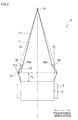
- Fig. 3 is used for illustrating the layout positions of the yarn stitching restraining guides. It is noted that the contact roller 7 is not illustrated in Fig. 3 . Furthermore, in reality, the yarn Y guided from the traverse guide 21 contacts the contact roller 7 first and then moves along its circumference and then contacts the bobbin 9. In this regard, for the sake of simplicity, the yarn Y guided from the traverse guide 21 is supposed to directly contact the bobbin 9 rather than the contact roller 7.
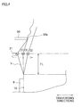
- Fig. 4 is used for illustrating the yarn forms of the yarn when the traverse guide is reversed. In Fig. 4 , the contact point between the yarn Y and the bobbin 9 gradually moves in a traversing direction when the traverse guide 21 is traversed. This movement, however, is ignored because it is very short in distance.
- two yarn stitching restraining guides 50 are provided for a single traverse unit 6 (i.e., a single yarn Y).
- An end face 50a of each of the two yarn stitching restraining guides 50 is positioned to be on the traversal center side of the line L1 connecting the traverse guide 21 at the reversal position with the fulcrum guide 19 and to be on the line L2 connecting the fulcrum guide 19 with the traverse guide 21 having reached the edge of the winding target range on the bobbin 9.
- an interval FL which is a free length of the yarn Y after the yarn Y on the traverse guide 21 is released from the traverse guide 21 and before the yarn Y contacts the bobbin 9.
- the tilt of the yarn Y in the free length interval FL is a synthetic vector of the rotation speed of the bobbin holder 5 (i.e., the speed of winding of the yarn Y onto the bobbin 9) and the traversing speed of the traverse guide 21.
- the traverse guide 21 traverses the yarn beyond the edge X1 of the winding target range of the wound yarns Y on the bobbin 9.
- the direct distance between the contact point where the running yarn Y contacts the traverse guide 21 and the contact point where the running yarn Y contacts the bobbin 9 becomes short for a moment.
- the distance becomes the shortest when the traverse guide 21 is at the same position as the edge X1 of the yarn Y wound onto the winding target range on the bobbin 9 in the axial directions of the bobbin 9 (i.e., (2) in Fig. 4 ).
- the form of the yarn Y is changed from the straight shape because the length of the yarn Y running in the free length interval between the traverse guide 21 and the bobbin 9 is unchanged, with the result that the yarn Y having an unpredictable shape is wound at the edge X1 of the winding target range on the bobbin 9 and hence the yarn stitching occurs.
- the yarn Y is traversed while changing its form in the order of (3) ⁇ (2) ⁇ (1) ⁇ (2) ⁇ (3) as shown in Fig. 4 .
- the traverse guide 21 is reversed, the running yarn Y contacts the yarn stitching restraining guide 50 and hence running resistance is imparted to the yarn Y.
- the tension on the yarn Y is increased on the downstream side (bobbin 9 side) of the part where the running resistance is imparted to the yarn Y, and consequently the slack in the yarn Y is easily removed.
- the yarn stitching restraining guide 50 can remove the slack in the yarn running between the traverse guide and the bobbin and restrain the occurrence of the yarn stitching as described above, when the yarn stitching restraining guide 50 is at least on the traversal center side of the line L1 connecting the traverse guide 21 at the reversal position (traversal end) with the fulcrum guide 19, i.e., on the traversal center side of the position where the yarn running at the traversal end starts to be slackened.
- the slack in the yarn running between the traverse guide and the bobbin is more effectively removed when the end face 50a of the yarn stitching restraining guide 50 is on the traversal center side of the line L1 and on the line L2 which connects the fulcrum guide 19 with the traverse guide 21 having reached the edge of the winding target range on the bobbin 9.
- the running resistance imparted to the yarn Y by the yarn stitching restraining guide 50 may be changed by changing the material of the guide and the surface roughness of the surface contacting the yarn Y, in addition to the layout position of the yarn stitching restraining guide 50.
- Second Embodiment of the present invention will be described.
- the yarn winding device 1 is arranged so that the yarn stitching restraining guides 50 which have been described in First Embodiment are movable.
- the positions of the yarn stitching restraining guides 50 are moved by the contact position control unit 44.
- the above-described cylinder 34 and contact position control unit 44 for moving the yarn stitching restraining guides 50 are prerequisite.
- the reversal position of the traverse guide 21 moves inward as the amount of wound yarns Y increases (L4 ⁇ L3).
- the cylinder 34 is controlled by the contact position control unit 44 so that the yarn stitching restraining guide 50 is moved inward (i.e., toward the center of the traversal width). With this, the yarn stitching restraining guide 50 surely contacts the running yarn Y when the traverse guide 21 is reversed, with the result that the yarn stitching is more effectively restrained.
- the yarn stitching is restrained by arranging the yarn stitching restraining guide 50 to be movable in accordance with the winding target range on the bobbin 9, it is possible to narrow the tapering angle to increase the total amount of the yarns wound in a single package 10, without increasing the diameter.
- the occurrence of the yarn stitching is restrained by the yarn stitching restraining guides 50.
- any arrangements may be adopted in place of the yarn stitching restraining guides 50 on condition that the slack in the yarn Y in the free length interval is removed.
- the rotation speed of the bobbin holder 5 is temporarily increased by controlling the winding control unit 42 by the rotation motor 32.
- the yarn stitching restraining guide 50 may be movably fixed to the elevation frame 3 by an unillustrated screw or the like, when it is unnecessary to move the yarn stitching restraining guide 50 during the winding of the yarns Y and the yarn stitching restraining guide 50 is moved only when, for example, the yarn type or the winding target range on the bobbin 9 is changed while the winding of the yarns Y is stopped. In this case, an operator loosens the screw, moves the yarn stitching restraining guide 50, and tightens the screw.
- the yarn stitching restraining guide 50 may be arranged to mechanically or electrically move in sync with a change in the traversal width of the traverse guide 21.
- An arm-type traverse unit is a device which reciprocally moves, in traversing directions, an arm member having a guide at its leading end by a drive motor.
Landscapes
- Engineering & Computer Science (AREA)
- Textile Engineering (AREA)
- Winding Filamentary Materials (AREA)
- Tension Adjustment In Filamentary Materials (AREA)
- Guides For Winding Or Rewinding, Or Guides For Filamentary Materials (AREA)
Abstract
Description
- The present invention relates to a yarn winding device which traverses yarns by a traverse unit and wind them onto a bobbin so as to form a package.
- A known yarn winding device has a traverse unit traversing yarns in the axial directions of bobbins and forms a package by winding yarns onto a bobbin while traversing the yarns. In this regard, various methods of traversing yarns by the traverse unit of the yarn winding device have been known. For example, Patent Document 1 (Japanese Unexamined Patent Publication No.
238645/1993 Tokukaihei 5-238645 - On the other hand, Patent Document 2 (Japanese Examined Patent Publication No.
3985/1979 Tokukosho 54-3985 Fig. 4 )) recites a rotating-blade-type traverse unit which has two blade-shaped traverse guides which are superposed onto each other and rotate in reverse directions. In this traverse unit, after a yarn is moved on one side in the axial directions of the bobbin by one traverse guide, the yarn is passed to the other traverse guide at the end point (i.e. an edge of the winding target range on the bobbin), and the yarn is moved to the other side in the axial directions of the bobbin by the other traverse guide. - This
Patent Document 2 aims at reducing the yarn accumulation (so-called saddle bag) at the end portions of the package. To achieve this object, the technology recited in the document utilizes the yarn returning effect at the respective traversal ends, in a traverse unit which winds yarns such that a yarn guided by a traverse guide to a traversal end comes off from the traverse guide and is then engaged with another traverse guide and guided in a reverse direction. More specifically, position regulation guides are provided at the traversal ends to arrange the speed of the yarn returning from a traversal end to be higher than the speed of the movement of the traverse guide, with the result that the yarn accumulation at the traversal ends is alleviated. - Both of the traversing methods of
Patent Documents - This cause of the problem will be described below with reference to
Fig. 6 . As shown inFig. 6 , a yarn Y is traversed while changing its form in the order of (3) → (2) → (1) → (2) → (3). When atraverse guide 80 goes beyond the winding target range of abobbin 81 and is reversed, the linear distance between the contact point Al of the running yarn Y with thetraverse guide 80 and the contact point A2 of the running yarn Y with thebobbin 81 is short. On the other hand, normally the speed of winding onto the bobbin 81 (i.e. the speed of supplying the yarn) is always constant even when thetraverse guide 80 is reversed. For this reason, even when the distance is short as above, the length of the yarn Y running between thetraverse guide 80 and thebobbin 81 remains the same. As a result, when thetraverse guide 80 is reversed, the yarn Y running between thetraverse guide 80 and thebobbin 81 is slackened for a moment, as indicated by (2) inFig. 6 . The inventor assumes that the yarn stitching at an edge portion tends to occur when such a slackened yarn is wound onto thebobbin 81. - An object of the present invention is therefore to restrain the occurrence of yarn stitching by eliminating the slack in a yarn, which occurs between a bobbin and a traverse guide when the traverse guide is reversed.
- A yarn winding device of the present invention includes: a winding unit which winds a yarn onto a bobbin; a traverse unit which reciprocally moves the running yarn in axial directions of the bobbin; and a slack removal unit which removes the slack in the yarn running between the traverse guide and the bobbin, when the traverse guide is reversed.
- According to the yarn winding device of the present invention, since the slack in a yarn running between the traverse guide and the bobbin is removed when the traverse guide is reversed, a yarn having a stable yarn form is wound at an edge of the winding target range of the bobbin, with the result that the occurrence of the yarn stitching is restrained.
- In addition to the above, the yarn winding device is preferably arranged so that the slack removal unit is provided on a side upstream of the traverse guide in a direction in which the yarn runs, and is a resistance imparting unit which contacts the running yarn to impart, to the yarn, running resistance against the direction in which the yarn runs, when the traverse guide is reversed.
- According to this arrangement, the slack in the yarn is easily removed only by imparting running resistance against the running direction of the yarn when the traverse guide is reversed, as the tension on the yarn is increased on the side downstream of the resistance imparting unit.
- In addition to the above, the yarn winding device preferably further includes: a fulcrum guide which is fixedly provided on the side upstream of the traverse guide in the direction in which the yarn runs; and a contact guide which is provided between the fulcrum guide and the traverse guide and functions as the resistance imparting unit, the contact guide externally contacting, in the axial directions of the bobbin, the yarn between the fulcrum guide and the traverse guide, on a line connecting the fulcrum guide with the traverse guide when the traverse guide reaches an edge of a winding target range of the bobbin.
- When no contact guide is provided, the yarn running between the traverse guide and the bobbin is maximally slackened when the direct distance between the contact point of the running yarn with the traverse guide and the contact point of the running yarn with the bobbin becomes the shortest, i.e., when the traverse guide reaches the edge of the winding target range of the bobbin. In the present invention, the contact guide contacts the yarn running between the fulcrum guide and the bobbin, on the line L2 (see
Fig. 3 ) connecting the fulcrum guide with the traverse guide at the aforesaid position. For example, as the contact guide gets closer to the traversal center and away from the line L2, the angle of the yarn contacting and bended by the contact guide increases, and hence the damage onto the running yarn between the traverse guide and the bobbin becomes serious in comparison with the effect of removing the slack in the yarn. In this regard, as the contact guide contacts the yarn running between the fulcrum guide and the bobbin on the line L2, it is possible to effectively remove the slack in the yarn running between the traverse guide and the bobbin. - In addition to the above, the yarn winding device preferably further includes: a position change unit which changes a position of the contact guide in the axial directions of the bobbin; and a position control unit which controls the position change unit.
- In addition to the above, The yarn winding device is preferably arranged so that the traverse unit is able to change a reversal position where the traverse guide is reversed, and the position control unit controls the position change unit so as to move the contact guide in accordance with a direction in which the reversal position of the traverse guide is changed, while the yarn is being wound onto the bobbin.
- For example, when a tapered-end package is formed, the end faces of the package may be arranged to tilt axially outward. In such a case, the reversal position of the traverse guide moves inward as the amount of wound yarns increases. In accordance with this movement, the contact guide is moved inward. With this, the contact guide surely contacts the running yarn when the traverse guide is reversed, with the result that the yarn stitching is more effectively restrained.
- In addition to the above, the yarn winding device preferably further includes: a winding control unit which controls a rotation speed of the bobbin rotated by the winding unit, the winding control unit controlling the winding unit so as to function as the slack removal unit which removes the slack in the yarn running between the traverse guide and the bobbin, by temporarily increasing the rotation speed of the bobbin when the traverse guide is reversed.
- According to this arrangement, by temporarily increasing the rotation speed of the bobbin when the traverse guide is reversed, the slack in the yarn running between the traverse guide and the bobbin is removed with less decrease in the quality of the yarn, as compared to the arrangement in which the slack is removed by imparting running resistance to the yarn.
- By removing the slack in the yarn between the traverse guide and the bobbin when the traverse guide is reversed, the yarn having the desired shape is wound at the edge of the winding target range on the bobbin, the occurrence of the yarn stitching is restrained.
-
-
Fig. 1 is a profile of a yarn winding device according to First Embodiment of the present invention. -
Fig. 2 is a front elevation of the yarn winding device according to First Embodiment of the present invention. -
Fig. 3 illustrates a position of a yarn stitching restraining guide. -
Fig. 4 illustrates the form of the yarn when the traverse guide is reversed. -
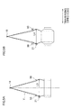
Fig. 5A illustrates a position of the yarn stitching restraining guide in relation to the winding target range of the bobbin, when the winding starts. -
Fig. 5B illustrates a position of the yarn stitching restraining guide in relation to the winding target range of the bobbin, when the winding ends. -
Fig. 6 illustrates the forms of a yarn when the traverse guide is reversed in a known case. - Now, First Embodiment of the present invention will be described.
Fig. 1 is a profile of a yarn winding device according to First Embodiment of the present invention.Fig. 2 is a front elevation of the yarn winding device. As shown inFig. 1 , ayarn winding device 1 successively receives a plurality of yarns Y from an unillustrated spinning machine provided above. Theyarn winding device 1 is arranged to form a plurality ofpackages 10 by winding the yarns Y supplied from the spinning machine onto a plurality ofbobbins 9. - As shown in
Fig. 1 andFig. 2 , theyarn winding device 1 includes components such as amain body frame 2, anelevation frame 3 provided to themain body frame 2 to be vertically movable, a disc-shaped turret 4 rotatably provided to themain body frame 2, two bobbin holders 5 (winding units) each of which is supported by theturret 4 at one end and to which a plurality ofbobbins 9 are attached, atraverse unit 6 which traverses the yarn Y which is to be wound onto thebobbin 9, acontact roller 7 which is able to contact thebobbins 9 attached to thebobbin holders 5, and acontroller 8 which controls the overall operation by controlling the components. - The
turret 4 is disc-shaped and is rotatably attached to themain body frame 2. At two positions which are symmetrical with respect to ashaft 4a which is the rotation center of theturret 4, ends of the twobobbin holders 5 are connected, respectively. The twobobbin holders 5 are rotatably protrude from theturret 4. The twobobbin holders 5 are arranged to rotate together with theturret 4. To each of the twobobbin holders 5, a plurality ofbobbins 9 are attached in series in the axial directions of thebobbin holder 5. - The
turret 4 is rotated about theshaft 4a by arotation motor 31. As theturret 4 is rotated, each of the twobobbin holders 5 moves between a winding position P1 at which thebobbin holder 5 contacts thecontact roller 7 and yarns Y are wound onto thebobbins 9 and a standby position P2 which is below the winding position P1 and is point-symmetrical with the winding position P1 with respect to theshaft 4a of theturret 4. After the yarns are wound onto thebobbins 9 attached to thebobbin holder 5 at the winding position P1 andpackages 10 are formed, thisbobbin holder 5 at the winding position P1 is switched to the standby position P2 whereas thebobbin holder 5 at the winding position P2 is switched to the winding position P1. - Each of the two
bobbin holders 5 supported by theturret 4 is rotated by therotation motor 32. As thebobbin holder 5 at the winding position P1 is rotated, the yarns Y are wound onto thebobbins 9 attached to thisbobbin holder 5. - The
elevation frame 3 is a long frame extending in the axial directions of thebobbin holder 5, and supported by themain body frame 2 at its base end in the longitudinal direction. Theelevation frame 3 is connected to a rod of an unillustrated cylinder fixed to themain body frame 2, and is vertically moved (i.e. moved in the direction away from the bobbin holder 5) with respect to themain body frame 2, as the cylinder is driven. - The
traverse unit 6 is provided on theelevation frame 3 and includes components such as fulcrum guides 19, atraverse cam 20, traverse guides 21, and atraverse motor 33. - The fulcrum guides 19 are provided around the upper end of the
elevation frame 3. The yarns Y supplied from the spinning machine are placed onto these fulcrum guides 19, and they function as the traversal fulcrums of the yarns Y. Thetraverse cam 20 is provided to be in parallel to thebobbin holder 5 and is rotatably supported by theelevation frame 3. Thetraverse cam 20 has a helical cam groove on its circumference, and is rotated by thetraverse motor 33. - The traverse guides 21 move along the cam groove as the
traverse cam 20 is rotated, and reciprocate in the axial directions of the traverse cam 20 (bobbin holder 5). Eachtraverse guide 21 is arranged to sandwich a running yarn Y by twoguide portions 21a in the axial directions of thebobbin holder 5. Thetraverse guide 21 guides the yarn Y running through thefulcrum guide 19 to thecontact roller 7 while traversing, by using thefulcrum guide 19 as a fulcrum, the yarn Y in the axial directions (traversing directions) of thebobbin holder 5. - Between the fulcrum guides 19 and the traverse guides 21 of the
traverse unit 6 of theelevation frame 3, yarn stitching restraining guides 50 are provided to be able to contact the yarns Y traversed by thetraverse guide 21. Each yarnstitching restraining guide 50 is connected to the rod of thecylinder 34 fixed to theelevation frame 3. As thecylinder 34 is driven, the yarnstitching restraining guide 50 moves in the traversing directions with respect to theelevation frame 3. This yarnstitching restraining guide 50 will be detailed later. It is noted that, in First Embodiment, the yarn stitching restraining guides 50 may be fixed and immovable. On the other hand, the yarnstitching restraining guide 50 must be arranged to be movable in later-described Second Embodiment. - The
elevation frame 3 is connected to a supporting frame 11, and two supportingportions 11a rotatably supporting thecontact roller 7 are provided at the respective longitudinal end portions of the supporting frame 11. The supporting frame 11 is long along the length of theelevation frame 3. Further, the supporting frame 11 is connected to theguide plate 12 at the longitudinal end portions of the supporting frame 11, and is arranged to be vertically movable with respect to the guide plate 12 (elevation frame 3) . - The
contact roller 7 is supported by the two supportingportions 11a of the supporting frame 11 to be in parallel to thebobbin holder 5. Thiscontact roller 7 is arranged to be able to contact the outer circumferences of thebobbins 9 attached to thebobbin holder 5 at the winding position P1 or thepackages 10 formed by winding the yarns Y onto thebobbins 9. When the yarns are wound onto thebobbins 9, thecontact roller 7 is rotated by the rotation of thebobbin holder 5 while applying a predetermined contact pressure onto thepackages 10, so as to adjust the shape of eachpackage 10. The supporting frame 11 and thecontact roller 7 are guided by theguide plate 12 to change their relative positions with respect to theelevation frame 3 in the direction to approach thebobbins 9 at the winding position P1 (i.e. downward direction) or in the direction away from these bobbins 9 (i.e. upward direction). - Now, the
controller 8 performing the overall control of theyarn winding device 1 will be described. As shown inFig. 2 , thecontroller 8 may include components such as a CPU (Central Processing Unit), a ROM (Read Only Memory) storing various programs and data for performing the overall control of theyarn winding device 1, and a RAM (Random Access Memory) temporarily storing data processed by the CPU, and perform below-described various controls as a program stored in the ROM is executed by the CPU. Alternatively, thecontroller 8 may be hardware composed by various circuits including an arithmetic circuit. - The
controller 8 includes a holderswitching control unit 41, a windingcontrol unit 42, atraverse control unit 43, and a contactposition control unit 44. - The holder
switching control unit 41 drives therotation motor 31 to rotate theturret 4, so as to switch the position of each of the twobobbin holders 5 between the winding position P1 and the standby position P2. The windingcontrol unit 42 drives therotation motor 32 to rotate thebobbin holder 5 at the winding position P1, so as to wind the yarns Y onto thebobbins 9 attached to thebobbin holder 5. - The
traverse control unit 43 drives thetraverse motor 33 to rotate thetraverse cam 20, so as to traverse the yarn Y sandwiched between the traverse guides 21 in the traversing directions by reciprocally moving the traverse guides 21 in the traversing directions. The contactposition control unit 44 moves thecylinder 34 so as to change the positions of the yarn stitching restraining guides 50 in the traversing directions. In First Embodiment, the yarn stitching restraining guides 50 may be fixed as described above and the contactposition control unit 44 may be unnecessary. On the other hand, in later-described Second Embodiment, the yarn stitching restraining guides 50 must be movable and the contactposition control unit 44 is necessary. Thecontroller 8 includes the contactposition control unit 44 for this reason. - Now, after describing the layout positions of the yarn stitching restraining guides 50, the traversing movement of the
traverse unit 6 will be described with reference toFig. 3 andFig. 4 .Fig. 3 is used for illustrating the layout positions of the yarn stitching restraining guides. It is noted that thecontact roller 7 is not illustrated inFig. 3 . Furthermore, in reality, the yarn Y guided from thetraverse guide 21 contacts thecontact roller 7 first and then moves along its circumference and then contacts thebobbin 9. In this regard, for the sake of simplicity, the yarn Y guided from thetraverse guide 21 is supposed to directly contact thebobbin 9 rather than thecontact roller 7.Fig. 4 is used for illustrating the yarn forms of the yarn when the traverse guide is reversed. InFig. 4 , the contact point between the yarn Y and thebobbin 9 gradually moves in a traversing direction when thetraverse guide 21 is traversed. This movement, however, is ignored because it is very short in distance. - As shown in
Fig. 3 , two yarn stitching restraining guides 50 are provided for a single traverse unit 6 (i.e., a single yarn Y). Anend face 50a of each of the two yarn stitching restraining guides 50 is positioned to be on the traversal center side of the line L1 connecting thetraverse guide 21 at the reversal position with thefulcrum guide 19 and to be on the line L2 connecting thefulcrum guide 19 with thetraverse guide 21 having reached the edge of the winding target range on thebobbin 9. - Between the
traverse guide 21 and thebobbin 9, there is a free length interval where the yarn Y runs in the air without any binding, i.e., an interval FL which is a free length of the yarn Y after the yarn Y on thetraverse guide 21 is released from thetraverse guide 21 and before the yarn Y contacts thebobbin 9. When the yarn Y is tensioned, usually the yarn Y in the free length interval FL straightly connects thetraverse guide 21 with thebobbin 9. The tilt of the yarn Y in the free length interval FL is a synthetic vector of the rotation speed of the bobbin holder 5 (i.e., the speed of winding of the yarn Y onto the bobbin 9) and the traversing speed of thetraverse guide 21. - When the yarn Y tilting with respect to the axial directions of the
bobbin 9 as above is wound, thetraverse guide 21 traverses the yarn beyond the edge X1 of the winding target range of the wound yarns Y on thebobbin 9. In this connection, when thetraverse guide 21 goes beyond the winding target range and reverses, the direct distance between the contact point where the running yarn Y contacts thetraverse guide 21 and the contact point where the running yarn Y contacts thebobbin 9 becomes short for a moment. In particular, the distance becomes the shortest when thetraverse guide 21 is at the same position as the edge X1 of the yarn Y wound onto the winding target range on thebobbin 9 in the axial directions of the bobbin 9 (i.e., (2) inFig. 4 ). If the yarnstitching restraining guide 50 is not provided in the case above, the form of the yarn Y is changed from the straight shape because the length of the yarn Y running in the free length interval between thetraverse guide 21 and thebobbin 9 is unchanged, with the result that the yarn Y having an unpredictable shape is wound at the edge X1 of the winding target range on thebobbin 9 and hence the yarn stitching occurs. - In the present invention, the yarn Y is traversed while changing its form in the order of (3) → (2) → (1) → (2) → (3) as shown in
Fig. 4 . When thetraverse guide 21 is reversed, the running yarn Y contacts the yarnstitching restraining guide 50 and hence running resistance is imparted to the yarn Y. As a result, the tension on the yarn Y is increased on the downstream side (bobbin 9 side) of the part where the running resistance is imparted to the yarn Y, and consequently the slack in the yarn Y is easily removed. As the form of the yarn Y in the free length interval FL immediately before being wound onto thebobbin 9 at the reversal of thetraverse guide 21 is stabilized and the yarn Y having the desired shape is wound at the edge X1 of the winding target range on thebobbin 9, the occurrence of the yarn stitching is restrained. - As such, the yarn
stitching restraining guide 50 can remove the slack in the yarn running between the traverse guide and the bobbin and restrain the occurrence of the yarn stitching as described above, when the yarnstitching restraining guide 50 is at least on the traversal center side of the line L1 connecting thetraverse guide 21 at the reversal position (traversal end) with thefulcrum guide 19, i.e., on the traversal center side of the position where the yarn running at the traversal end starts to be slackened. Furthermore, the slack in the yarn running between the traverse guide and the bobbin is more effectively removed when theend face 50a of the yarnstitching restraining guide 50 is on the traversal center side of the line L1 and on the line L2 which connects thefulcrum guide 19 with thetraverse guide 21 having reached the edge of the winding target range on thebobbin 9. This is because, for example, as theend face 50a of the yarnstitching restraining guide 50 gets closer to the traversal center and away from the line L2, the angle of the yarn Y contacting and bended by the yarnstitching restraining guide 50 increases, and hence the damage onto the running yarn Y between thetraverse guide 21 and thebobbin 9 becomes serious in comparison with the effect of removing the slack in the yarn Y. - The running resistance imparted to the yarn Y by the yarn
stitching restraining guide 50 may be changed by changing the material of the guide and the surface roughness of the surface contacting the yarn Y, in addition to the layout position of the yarnstitching restraining guide 50. - Now, Second Embodiment of the present invention will be described. In Second Embodiment, the
yarn winding device 1 is arranged so that the yarn stitching restraining guides 50 which have been described in First Embodiment are movable. The positions of the yarn stitching restraining guides 50 are moved by the contactposition control unit 44. In other words, the above-describedcylinder 34 and contactposition control unit 44 for moving the yarn stitching restraining guides 50 are prerequisite. - Now, the following will describe cases where the technology is used in three different winding methods.
- (1) When a belt-type traverse unit recited in Japanese Unexamined Patent Publication No.
2010-163275 drum traverse unit 6 of First Embodiment, the traversal width is changeable. The belt-type traverse unit reciprocates an endless belt having guides, in traversing directions by a drive motor. The traversal width of theyarn guide 4 ofPublication 1, i.e., the reversal positions of theyarn guide 4 are changeable. With this arrangement, the winding target range of the yarns Y wound onto thebobbin 9 is changed, for example, to form a tapered shape, so that a tapered-end package 10 whose end face is tilted radially outward is formed. - In such a case, as shown in
Fig. 5A and Fig. 5B , the reversal position of thetraverse guide 21 moves inward as the amount of wound yarns Y increases (L4<L3). In accordance with this movement, thecylinder 34 is controlled by the contactposition control unit 44 so that the yarnstitching restraining guide 50 is moved inward (i.e., toward the center of the traversal width). With this, the yarnstitching restraining guide 50 surely contacts the running yarn Y when thetraverse guide 21 is reversed, with the result that the yarn stitching is more effectively restrained. - In addition to the above, since the yarn stitching is restrained by arranging the yarn
stitching restraining guide 50 to be movable in accordance with the winding target range on thebobbin 9, it is possible to narrow the tapering angle to increase the total amount of the yarns wound in asingle package 10, without increasing the diameter. -
- (2) As shown in Japanese Unexamined Patent Publication No.
2010-189127 Fig. 6 ) to restrain the package end face from bulging, i.e., when the yarn layer angle is increased by increasing the traveling speed of thetraverse guide 21 by thetraverse control unit 43 shown inFig. 2 in the case of Second Embodiment, the yarnstitching restraining guide 50 is moved inward (toward the center of the traversal width) by the contactposition control unit 44 in sync with the timing to increase the yarn layer angle. -
- (3) When creeping (saddle bag prevention) is carried out by increasing or decreasing the free length interval FL, the traversal width is changed by changing the distance between the
traverse guide 21 and thepackage 10 by moving theelevation frame 3 shown inFig. 2 upward or downward. In so doing, the reversal position of the yarns Y gradually moves inward. In sync with this movement, thecylinder 34 is controlled by the contactposition control unit 44 so that the yarnstitching restraining guide 50 is moved inward (toward the center of the traversal width). An effect equal to the effect of (1) is achieved by this arrangement. - Now, various modifications of the embodiments above will be described. It is noted that the same components as in the embodiments above are denoted by the same reference numerals as in the embodiments, respectively, and the description thereof will be omitted.
- In the embodiments above, the occurrence of the yarn stitching is restrained by the yarn stitching restraining guides 50. In this regard, any arrangements may be adopted in place of the yarn stitching restraining guides 50 on condition that the slack in the yarn Y in the free length interval is removed. For example, when the
traverse guide 21 is reversed, the rotation speed of thebobbin holder 5 is temporarily increased by controlling the windingcontrol unit 42 by therotation motor 32. According to this arrangement, as compared to the arrangement of removing the slack in the yarn Y by tensioning the yarn Y by applying a running resistance to the yarn Y by the yarnstitching restraining guide 50, adverse effects on the yarn quality are alleviated when removing the slack in the yarn Y running between thetraverse guide 21 and thebobbin 9. - In addition to the above, the yarn
stitching restraining guide 50 may be movably fixed to theelevation frame 3 by an unillustrated screw or the like, when it is unnecessary to move the yarnstitching restraining guide 50 during the winding of the yarns Y and the yarnstitching restraining guide 50 is moved only when, for example, the yarn type or the winding target range on thebobbin 9 is changed while the winding of the yarns Y is stopped. In this case, an operator loosens the screw, moves the yarnstitching restraining guide 50, and tightens the screw. - While the embodiments are arranged so that the position of the yarn
stitching restraining guide 50 is changed by controlling thecylinder 34 by the contactposition control unit 44 in accordance with the traversal width of thetraverse guide 21 controlled by thetraverse control unit 43, the yarnstitching restraining guide 50 may be arranged to mechanically or electrically move in sync with a change in the traversal width of thetraverse guide 21. - In addition to the above, while the embodiments above deal with the cam drum traverse unit and the belt-type traverse unit, the present invention may be used in other types of traverse units, e.g. an arm-type traverse unit, on condition that a guide is reciprocally moved in the traversing directions. An arm-type traverse unit is a device which reciprocally moves, in traversing directions, an arm member having a guide at its leading end by a drive motor.
Claims (6)
- A yarn winding device comprising:a winding unit which winds a yarn onto a bobbin;a traverse unit which reciprocally moves the running yarn in axial directions of the bobbin; anda slack removal unit which removes the slack in the yarn running between the traverse guide and the bobbin, when the traverse guide is reversed.
- The yarn winding device according to claim 1 wherein,
the slack removal unit is provided on a side upstream of the traverse guide in a direction in which the yarn runs, and is a resistance imparting unit which contacts the running yarn to impart, to the yarn, running resistance against the direction in which the yarn runs, when the traverse guide is reversed. - The yarn winding device according to claim 1 or 2, further comprising:a fulcrum guide which is fixedly provided on the side upstream of the traverse guide in the direction in which the yarn runs; and a contact guide which is provided between the fulcrum guide and the traverse guide and functions as the resistance imparting unit,the contact guide externally contacting, in the axial directions of the bobbin, the yarn between the fulcrum guide and the traverse guide, on a line connecting the fulcrum guide with the traverse guide when the traverse guide reaches an edge of a winding target range of the bobbin.
- The yarn winding device according to one of claims 1 to 3, further comprising:a position change unit which changes a position of the contact guide in the axial directions of the bobbin; and a position control unit which controls the position change unit.
- The yarn winding device according to one of claims 1 to 4, wherein,
the traverse unit is able to change a reversal position where the traverse guide is reversed, and the position control unit controls the position change unit so as to move the contact guide in accordance with a direction in which the reversal position of the traverse guide is changed, while the yarn is being wound onto the bobbin. - The yarn winding device according to one of claims 1 to 5, further comprising:a winding control unit which controls a rotation speed of the bobbin rotated by the winding unit,the winding control unit controlling the winding unit so as to function as the slack removal unit which removes the slack in the yarn running between the traverse guide and the bobbin by temporarily increasing the rotation speed of the bobbin when the traverse guide is reversed.
Applications Claiming Priority (1)
| Application Number | Priority Date | Filing Date | Title |
|---|---|---|---|
| JP2010277848A JP5730557B2 (en) | 2010-12-14 | 2010-12-14 | Yarn winding machine |
Publications (3)
| Publication Number | Publication Date |
|---|---|
| EP2465802A2 true EP2465802A2 (en) | 2012-06-20 |
| EP2465802A3 EP2465802A3 (en) | 2013-08-21 |
| EP2465802B1 EP2465802B1 (en) | 2014-10-15 |
Family
ID=44992774
Family Applications (1)
| Application Number | Title | Priority Date | Filing Date |
|---|---|---|---|
| EP11189514.0A Active EP2465802B1 (en) | 2010-12-14 | 2011-11-17 | Yarn winding device |
Country Status (4)
| Country | Link |
|---|---|
| EP (1) | EP2465802B1 (en) |
| JP (1) | JP5730557B2 (en) |
| KR (1) | KR101518978B1 (en) |
| CN (1) | CN102530640B (en) |
Cited By (1)
| Publication number | Priority date | Publication date | Assignee | Title |
|---|---|---|---|---|
| WO2023186549A1 (en) * | 2022-04-01 | 2023-10-05 | Oerlikon Textile Gmbh & Co. Kg | Winding device for winding a spun yarn and method for winding a spun yarn |
Families Citing this family (5)
| Publication number | Priority date | Publication date | Assignee | Title |
|---|---|---|---|---|
| JP2015000777A (en) * | 2013-06-13 | 2015-01-05 | 村田機械株式会社 | Yarn winding machine |
| KR101805824B1 (en) * | 2016-04-14 | 2017-12-07 | 일진에이테크 주식회사 | Yarn winder |
| WO2020031457A1 (en) * | 2018-08-09 | 2020-02-13 | Tmtマシナリー株式会社 | Yarn winder |
| EP3865442B1 (en) * | 2018-10-09 | 2024-10-23 | TMT Machinery, Inc. | Yarn winder and package production method |
| DE102022001140A1 (en) * | 2022-04-01 | 2023-10-05 | Oerlikon Textile Gmbh & Co. Kg | Method for winding up a spinning thread and winding device for winding up a spinning thread |
Citations (4)
| Publication number | Priority date | Publication date | Assignee | Title |
|---|---|---|---|---|
| JPS543985B1 (en) | 1970-07-24 | 1979-02-28 | ||
| JPH05238645A (en) | 1992-02-28 | 1993-09-17 | Murata Mach Ltd | Filament take-up method and filament take-up machine |
| JP2010163275A (en) | 2009-01-19 | 2010-07-29 | Tmt Machinery Inc | Yarn winding apparatus, spinning winding machine using the yarn winding apparatus, yarn winding method, spinning winding method of adopting the yarn winding method and tapered end package |
| JP2010189127A (en) | 2009-02-18 | 2010-09-02 | Tmt Machinery Inc | Yarn winding machine and yarn winding method |
Family Cites Families (19)
| Publication number | Priority date | Publication date | Assignee | Title |
|---|---|---|---|---|
| FR1130106A (en) * | 1955-06-08 | 1957-01-31 | Rhodiaceta | Wire guide |
| DE1560539A1 (en) * | 1963-07-03 | 1970-01-02 | Reiners Walter Dr Ing | Device to avoid thread clipping in winding machines |
| US4090676A (en) * | 1974-03-25 | 1978-05-23 | Kamitsu Seisakusho, Ltd. | Yarn or thread guiding device |
| GB1461884A (en) * | 1974-04-02 | 1977-01-19 | Bekaert Sa Nv | Winding apparatus |
| US4007885A (en) * | 1975-06-17 | 1977-02-15 | E. I. Du Pont De Nemours And Company | Flexible traverse guide assembly |
| JPS543985A (en) * | 1977-06-10 | 1979-01-12 | Masaaki Miyanaga | Core drill |
| US4961546A (en) * | 1989-09-29 | 1990-10-09 | Platt Saco Lowell Corporation | Strand tension compensator |
| JPH03158358A (en) * | 1989-11-16 | 1991-07-08 | Toray Eng Co Ltd | Winder |
| GB9024396D0 (en) * | 1990-11-09 | 1991-01-02 | Jeftex Limited | Thread package building |
| JPH11322192A (en) * | 1998-05-14 | 1999-11-24 | Toray Ind Inc | Yarn traverse device and yarn package manufacturing method |
| JP3365975B2 (en) * | 1999-05-28 | 2003-01-14 | 東レエンジニアリング株式会社 | Yarn winding method |
| EP1126058A3 (en) * | 2000-02-17 | 2002-11-27 | Schärer Schweiter Mettler AG | Device for driving rotating components in an open-end spinning machine |
| DE10158975A1 (en) * | 2000-12-07 | 2002-06-13 | Barmag Barmer Maschf | Cruciform thread to bobbin winding process matches bobbin peripheral speed to transverse thread guide movement |
| JP4470338B2 (en) * | 2001-03-22 | 2010-06-02 | 東レ株式会社 | Traverse control method for yarn winding machine |
| JP4395828B2 (en) * | 2001-09-10 | 2010-01-13 | 村田機械株式会社 | Yarn winder with tension detector |
| EP1318097B1 (en) * | 2001-12-05 | 2010-02-24 | SSM Schärer Schweiter Mettler AG | Method and device for controlling the yarn tension in a textile machine and use of the method |
| JP4470487B2 (en) * | 2003-01-09 | 2010-06-02 | 東レ株式会社 | Yarn traverse device, yarn winding device, and method for manufacturing yarn package |
| ATE345302T1 (en) * | 2003-10-04 | 2006-12-15 | Ssm Ag | METHOD AND DEVICE FOR REGULATING THE THREAD TENSION ON A WINDING MACHINE, AND APPLICATION OF THE METHOD |
| JP4523053B2 (en) * | 2008-07-18 | 2010-08-11 | Tmtマシナリー株式会社 | Yarn winding machine |
-
2010
- 2010-12-14 JP JP2010277848A patent/JP5730557B2/en active Active
-
2011
- 2011-11-17 EP EP11189514.0A patent/EP2465802B1/en active Active
- 2011-11-18 KR KR1020110120705A patent/KR101518978B1/en active Active
- 2011-12-01 CN CN201110392496.8A patent/CN102530640B/en active Active
Patent Citations (4)
| Publication number | Priority date | Publication date | Assignee | Title |
|---|---|---|---|---|
| JPS543985B1 (en) | 1970-07-24 | 1979-02-28 | ||
| JPH05238645A (en) | 1992-02-28 | 1993-09-17 | Murata Mach Ltd | Filament take-up method and filament take-up machine |
| JP2010163275A (en) | 2009-01-19 | 2010-07-29 | Tmt Machinery Inc | Yarn winding apparatus, spinning winding machine using the yarn winding apparatus, yarn winding method, spinning winding method of adopting the yarn winding method and tapered end package |
| JP2010189127A (en) | 2009-02-18 | 2010-09-02 | Tmt Machinery Inc | Yarn winding machine and yarn winding method |
Cited By (1)
| Publication number | Priority date | Publication date | Assignee | Title |
|---|---|---|---|---|
| WO2023186549A1 (en) * | 2022-04-01 | 2023-10-05 | Oerlikon Textile Gmbh & Co. Kg | Winding device for winding a spun yarn and method for winding a spun yarn |
Also Published As
| Publication number | Publication date |
|---|---|
| EP2465802B1 (en) | 2014-10-15 |
| CN102530640B (en) | 2016-02-24 |
| KR101518978B1 (en) | 2015-05-11 |
| EP2465802A3 (en) | 2013-08-21 |
| KR20120066582A (en) | 2012-06-22 |
| CN102530640A (en) | 2012-07-04 |
| JP2012126484A (en) | 2012-07-05 |
| JP5730557B2 (en) | 2015-06-10 |
Similar Documents
| Publication | Publication Date | Title |
|---|---|---|
| EP2465802B1 (en) | Yarn winding device | |
| EP2548830B1 (en) | Spinning winder | |
| US9315358B2 (en) | Spun yarn winding device and spun yarn winding facility | |
| EP2221265B1 (en) | Yarn winding machine and yarn winding method | |
| MXPA06001926A (en) | Bobbin winding device. | |
| EP3865441B1 (en) | Yarn winding machine | |
| KR100745498B1 (en) | System for winding elastic yarn, winder for elastic yarn and method of winding elastic yarn | |
| EP3363756B1 (en) | Yarn winder | |
| JP6436751B2 (en) | Yarn winding device | |
| JP2024038600A (en) | Yarn winding machine | |
| JP2022145899A (en) | Yarn winding machine and package production method | |
| KR101675813B1 (en) | Device for adjusting yarn winding width using auxiliary guide | |
| EP4424623A1 (en) | Yarn winding machine | |
| JP7733594B2 (en) | Yarn winding machine | |
| JPS62275977A (en) | Turret type winder | |
| TWI731160B (en) | Belt-type false-twisting device | |
| JP7130365B2 (en) | Yarn guide pulley for a mechanical yarn accumulator located in the traverse triangle area in a textile machine work station producing cross-wound packages | |
| JP2000095440A (en) | Method and apparatus for switching yarn | |
| US3796383A (en) | Reciprocating yarn guide | |
| JPH10273268A (en) | How to switch yarns in the turret yarn winding machine | |
| CN116101846A (en) | Yarn tightener and textile machine work with same | |
| JP2023143807A (en) | Yarn winding machine | |
| HK1061007A1 (en) | Winder for elastomeric fibers | |
| HK1061007B (en) | Winder for elastomeric fibers |
Legal Events
| Date | Code | Title | Description |
|---|---|---|---|
| PUAI | Public reference made under article 153(3) epc to a published international application that has entered the european phase |
Free format text: ORIGINAL CODE: 0009012 |
|
| AK | Designated contracting states |
Kind code of ref document: A2 Designated state(s): AL AT BE BG CH CY CZ DE DK EE ES FI FR GB GR HR HU IE IS IT LI LT LU LV MC MK MT NL NO PL PT RO RS SE SI SK SM TR |
|
| AX | Request for extension of the european patent |
Extension state: BA ME |
|
| PUAL | Search report despatched |
Free format text: ORIGINAL CODE: 0009013 |
|
| AK | Designated contracting states |
Kind code of ref document: A3 Designated state(s): AL AT BE BG CH CY CZ DE DK EE ES FI FR GB GR HR HU IE IS IT LI LT LU LV MC MK MT NL NO PL PT RO RS SE SI SK SM TR |
|
| AX | Request for extension of the european patent |
Extension state: BA ME |
|
| RIC1 | Information provided on ipc code assigned before grant |
Ipc: B65H 54/38 20060101ALI20130716BHEP Ipc: B65H 67/048 20060101AFI20130716BHEP |
|
| 17P | Request for examination filed |
Effective date: 20131227 |
|
| RBV | Designated contracting states (corrected) |
Designated state(s): AL AT BE BG CH CY CZ DE DK EE ES FI FR GB GR HR HU IE IS IT LI LT LU LV MC MK MT NL NO PL PT RO RS SE SI SK SM TR |
|
| GRAP | Despatch of communication of intention to grant a patent |
Free format text: ORIGINAL CODE: EPIDOSNIGR1 |
|
| INTG | Intention to grant announced |
Effective date: 20140527 |
|
| GRAS | Grant fee paid |
Free format text: ORIGINAL CODE: EPIDOSNIGR3 |
|
| GRAA | (expected) grant |
Free format text: ORIGINAL CODE: 0009210 |
|
| AK | Designated contracting states |
Kind code of ref document: B1 Designated state(s): AL AT BE BG CH CY CZ DE DK EE ES FI FR GB GR HR HU IE IS IT LI LT LU LV MC MK MT NL NO PL PT RO RS SE SI SK SM TR |
|
| REG | Reference to a national code |
Ref country code: GB Ref legal event code: FG4D Ref country code: CH Ref legal event code: EP |
|
| REG | Reference to a national code |
Ref country code: IE Ref legal event code: FG4D |
|
| REG | Reference to a national code |
Ref country code: AT Ref legal event code: REF Ref document number: 691550 Country of ref document: AT Kind code of ref document: T Effective date: 20141115 |
|
| REG | Reference to a national code |
Ref country code: DE Ref legal event code: R096 Ref document number: 602011010580 Country of ref document: DE Effective date: 20141127 |
|
| REG | Reference to a national code |
Ref country code: NL Ref legal event code: VDEP Effective date: 20141015 |
|
| REG | Reference to a national code |
Ref country code: AT Ref legal event code: MK05 Ref document number: 691550 Country of ref document: AT Kind code of ref document: T Effective date: 20141015 |
|
| REG | Reference to a national code |
Ref country code: LT Ref legal event code: MG4D |
|
| PG25 | Lapsed in a contracting state [announced via postgrant information from national office to epo] |
Ref country code: NL Free format text: LAPSE BECAUSE OF FAILURE TO SUBMIT A TRANSLATION OF THE DESCRIPTION OR TO PAY THE FEE WITHIN THE PRESCRIBED TIME-LIMIT Effective date: 20141015 |
|
| PG25 | Lapsed in a contracting state [announced via postgrant information from national office to epo] |
Ref country code: FI Free format text: LAPSE BECAUSE OF FAILURE TO SUBMIT A TRANSLATION OF THE DESCRIPTION OR TO PAY THE FEE WITHIN THE PRESCRIBED TIME-LIMIT Effective date: 20141015 Ref country code: LT Free format text: LAPSE BECAUSE OF FAILURE TO SUBMIT A TRANSLATION OF THE DESCRIPTION OR TO PAY THE FEE WITHIN THE PRESCRIBED TIME-LIMIT Effective date: 20141015 Ref country code: NO Free format text: LAPSE BECAUSE OF FAILURE TO SUBMIT A TRANSLATION OF THE DESCRIPTION OR TO PAY THE FEE WITHIN THE PRESCRIBED TIME-LIMIT Effective date: 20150115 Ref country code: PT Free format text: LAPSE BECAUSE OF FAILURE TO SUBMIT A TRANSLATION OF THE DESCRIPTION OR TO PAY THE FEE WITHIN THE PRESCRIBED TIME-LIMIT Effective date: 20150216 Ref country code: IS Free format text: LAPSE BECAUSE OF FAILURE TO SUBMIT A TRANSLATION OF THE DESCRIPTION OR TO PAY THE FEE WITHIN THE PRESCRIBED TIME-LIMIT Effective date: 20150215 Ref country code: ES Free format text: LAPSE BECAUSE OF FAILURE TO SUBMIT A TRANSLATION OF THE DESCRIPTION OR TO PAY THE FEE WITHIN THE PRESCRIBED TIME-LIMIT Effective date: 20141015 |
|
| PG25 | Lapsed in a contracting state [announced via postgrant information from national office to epo] |
Ref country code: LV Free format text: LAPSE BECAUSE OF FAILURE TO SUBMIT A TRANSLATION OF THE DESCRIPTION OR TO PAY THE FEE WITHIN THE PRESCRIBED TIME-LIMIT Effective date: 20141015 Ref country code: RS Free format text: LAPSE BECAUSE OF FAILURE TO SUBMIT A TRANSLATION OF THE DESCRIPTION OR TO PAY THE FEE WITHIN THE PRESCRIBED TIME-LIMIT Effective date: 20141015 Ref country code: HR Free format text: LAPSE BECAUSE OF FAILURE TO SUBMIT A TRANSLATION OF THE DESCRIPTION OR TO PAY THE FEE WITHIN THE PRESCRIBED TIME-LIMIT Effective date: 20141015 Ref country code: AT Free format text: LAPSE BECAUSE OF FAILURE TO SUBMIT A TRANSLATION OF THE DESCRIPTION OR TO PAY THE FEE WITHIN THE PRESCRIBED TIME-LIMIT Effective date: 20141015 Ref country code: CY Free format text: LAPSE BECAUSE OF FAILURE TO SUBMIT A TRANSLATION OF THE DESCRIPTION OR TO PAY THE FEE WITHIN THE PRESCRIBED TIME-LIMIT Effective date: 20141015 Ref country code: PL Free format text: LAPSE BECAUSE OF FAILURE TO SUBMIT A TRANSLATION OF THE DESCRIPTION OR TO PAY THE FEE WITHIN THE PRESCRIBED TIME-LIMIT Effective date: 20141015 Ref country code: SE Free format text: LAPSE BECAUSE OF FAILURE TO SUBMIT A TRANSLATION OF THE DESCRIPTION OR TO PAY THE FEE WITHIN THE PRESCRIBED TIME-LIMIT Effective date: 20141015 Ref country code: GR Free format text: LAPSE BECAUSE OF FAILURE TO SUBMIT A TRANSLATION OF THE DESCRIPTION OR TO PAY THE FEE WITHIN THE PRESCRIBED TIME-LIMIT Effective date: 20150116 |
|
| PG25 | Lapsed in a contracting state [announced via postgrant information from national office to epo] |
Ref country code: BE Free format text: LAPSE BECAUSE OF NON-PAYMENT OF DUE FEES Effective date: 20141130 |
|
| REG | Reference to a national code |
Ref country code: CH Ref legal event code: PL |
|
| REG | Reference to a national code |
Ref country code: DE Ref legal event code: R097 Ref document number: 602011010580 Country of ref document: DE |
|
| PG25 | Lapsed in a contracting state [announced via postgrant information from national office to epo] |
Ref country code: DK Free format text: LAPSE BECAUSE OF FAILURE TO SUBMIT A TRANSLATION OF THE DESCRIPTION OR TO PAY THE FEE WITHIN THE PRESCRIBED TIME-LIMIT Effective date: 20141015 Ref country code: CH Free format text: LAPSE BECAUSE OF NON-PAYMENT OF DUE FEES Effective date: 20141130 Ref country code: SK Free format text: LAPSE BECAUSE OF FAILURE TO SUBMIT A TRANSLATION OF THE DESCRIPTION OR TO PAY THE FEE WITHIN THE PRESCRIBED TIME-LIMIT Effective date: 20141015 Ref country code: MC Free format text: LAPSE BECAUSE OF FAILURE TO SUBMIT A TRANSLATION OF THE DESCRIPTION OR TO PAY THE FEE WITHIN THE PRESCRIBED TIME-LIMIT Effective date: 20141015 Ref country code: LI Free format text: LAPSE BECAUSE OF NON-PAYMENT OF DUE FEES Effective date: 20141130 Ref country code: RO Free format text: LAPSE BECAUSE OF FAILURE TO SUBMIT A TRANSLATION OF THE DESCRIPTION OR TO PAY THE FEE WITHIN THE PRESCRIBED TIME-LIMIT Effective date: 20141015 Ref country code: CZ Free format text: LAPSE BECAUSE OF FAILURE TO SUBMIT A TRANSLATION OF THE DESCRIPTION OR TO PAY THE FEE WITHIN THE PRESCRIBED TIME-LIMIT Effective date: 20141015 Ref country code: EE Free format text: LAPSE BECAUSE OF FAILURE TO SUBMIT A TRANSLATION OF THE DESCRIPTION OR TO PAY THE FEE WITHIN THE PRESCRIBED TIME-LIMIT Effective date: 20141015 |
|
| PLBE | No opposition filed within time limit |
Free format text: ORIGINAL CODE: 0009261 |
|
| STAA | Information on the status of an ep patent application or granted ep patent |
Free format text: STATUS: NO OPPOSITION FILED WITHIN TIME LIMIT |
|
| REG | Reference to a national code |
Ref country code: IE Ref legal event code: MM4A |
|
| REG | Reference to a national code |
Ref country code: FR Ref legal event code: ST Effective date: 20150731 |
|
| 26N | No opposition filed |
Effective date: 20150716 |
|
| PG25 | Lapsed in a contracting state [announced via postgrant information from national office to epo] |
Ref country code: IE Free format text: LAPSE BECAUSE OF NON-PAYMENT OF DUE FEES Effective date: 20141117 |
|
| PG25 | Lapsed in a contracting state [announced via postgrant information from national office to epo] |
Ref country code: FR Free format text: LAPSE BECAUSE OF NON-PAYMENT OF DUE FEES Effective date: 20141215 |
|
| PG25 | Lapsed in a contracting state [announced via postgrant information from national office to epo] |
Ref country code: SI Free format text: LAPSE BECAUSE OF FAILURE TO SUBMIT A TRANSLATION OF THE DESCRIPTION OR TO PAY THE FEE WITHIN THE PRESCRIBED TIME-LIMIT Effective date: 20141015 |
|
| PG25 | Lapsed in a contracting state [announced via postgrant information from national office to epo] |
Ref country code: SM Free format text: LAPSE BECAUSE OF FAILURE TO SUBMIT A TRANSLATION OF THE DESCRIPTION OR TO PAY THE FEE WITHIN THE PRESCRIBED TIME-LIMIT Effective date: 20141015 |
|
| PG25 | Lapsed in a contracting state [announced via postgrant information from national office to epo] |
Ref country code: BG Free format text: LAPSE BECAUSE OF FAILURE TO SUBMIT A TRANSLATION OF THE DESCRIPTION OR TO PAY THE FEE WITHIN THE PRESCRIBED TIME-LIMIT Effective date: 20141015 |
|
| GBPC | Gb: european patent ceased through non-payment of renewal fee |
Effective date: 20151117 |
|
| PG25 | Lapsed in a contracting state [announced via postgrant information from national office to epo] |
Ref country code: TR Free format text: LAPSE BECAUSE OF FAILURE TO SUBMIT A TRANSLATION OF THE DESCRIPTION OR TO PAY THE FEE WITHIN THE PRESCRIBED TIME-LIMIT Effective date: 20141015 Ref country code: LU Free format text: LAPSE BECAUSE OF NON-PAYMENT OF DUE FEES Effective date: 20141117 Ref country code: HU Free format text: LAPSE BECAUSE OF FAILURE TO SUBMIT A TRANSLATION OF THE DESCRIPTION OR TO PAY THE FEE WITHIN THE PRESCRIBED TIME-LIMIT; INVALID AB INITIO Effective date: 20111117 Ref country code: MT Free format text: LAPSE BECAUSE OF FAILURE TO SUBMIT A TRANSLATION OF THE DESCRIPTION OR TO PAY THE FEE WITHIN THE PRESCRIBED TIME-LIMIT Effective date: 20141015 |
|
| PG25 | Lapsed in a contracting state [announced via postgrant information from national office to epo] |
Ref country code: GB Free format text: LAPSE BECAUSE OF NON-PAYMENT OF DUE FEES Effective date: 20151117 |
|
| PG25 | Lapsed in a contracting state [announced via postgrant information from national office to epo] |
Ref country code: MK Free format text: LAPSE BECAUSE OF FAILURE TO SUBMIT A TRANSLATION OF THE DESCRIPTION OR TO PAY THE FEE WITHIN THE PRESCRIBED TIME-LIMIT Effective date: 20141015 |
|
| PG25 | Lapsed in a contracting state [announced via postgrant information from national office to epo] |
Ref country code: AL Free format text: LAPSE BECAUSE OF FAILURE TO SUBMIT A TRANSLATION OF THE DESCRIPTION OR TO PAY THE FEE WITHIN THE PRESCRIBED TIME-LIMIT Effective date: 20141015 |
|
| P01 | Opt-out of the competence of the unified patent court (upc) registered |
Effective date: 20230426 |
|
| PGFP | Annual fee paid to national office [announced via postgrant information from national office to epo] |
Ref country code: DE Payment date: 20251124 Year of fee payment: 15 |
|
| PGFP | Annual fee paid to national office [announced via postgrant information from national office to epo] |
Ref country code: IT Payment date: 20251120 Year of fee payment: 15 |