EP2465770A2 - Anpassung von Flügeln für variable Wölbung zur optimalen Start- und Landekonfiguration - Google Patents
Anpassung von Flügeln für variable Wölbung zur optimalen Start- und Landekonfiguration Download PDFInfo
- Publication number
- EP2465770A2 EP2465770A2 EP11193899A EP11193899A EP2465770A2 EP 2465770 A2 EP2465770 A2 EP 2465770A2 EP 11193899 A EP11193899 A EP 11193899A EP 11193899 A EP11193899 A EP 11193899A EP 2465770 A2 EP2465770 A2 EP 2465770A2
- Authority
- EP
- European Patent Office
- Prior art keywords
- lift device
- differential
- deployable lift
- outboard
- flaps
- Prior art date
- Legal status (The legal status is an assumption and is not a legal conclusion. Google has not performed a legal analysis and makes no representation as to the accuracy of the status listed.)
- Granted
Links
- 230000033001 locomotion Effects 0.000 claims abstract description 136
- 238000000034 method Methods 0.000 claims abstract description 37
- 230000003213 activating effect Effects 0.000 claims abstract description 22
- 238000006073 displacement reaction Methods 0.000 description 22
- 238000010586 diagram Methods 0.000 description 8
- 230000008901 benefit Effects 0.000 description 7
- 230000004913 activation Effects 0.000 description 6
- 230000006870 function Effects 0.000 description 5
- 230000015654 memory Effects 0.000 description 4
- 239000000446 fuel Substances 0.000 description 3
- 230000008859 change Effects 0.000 description 2
- 230000003287 optical effect Effects 0.000 description 2
- 230000008569 process Effects 0.000 description 2
- 230000004044 response Effects 0.000 description 2
- 230000009471 action Effects 0.000 description 1
- 230000006399 behavior Effects 0.000 description 1
- 230000005540 biological transmission Effects 0.000 description 1
- 230000003247 decreasing effect Effects 0.000 description 1
- 230000001419 dependent effect Effects 0.000 description 1
- 230000003993 interaction Effects 0.000 description 1
- 238000005259 measurement Methods 0.000 description 1
- 230000004048 modification Effects 0.000 description 1
- 238000012986 modification Methods 0.000 description 1
- 239000000126 substance Substances 0.000 description 1
Images


Classifications
-
- B—PERFORMING OPERATIONS; TRANSPORTING
- B64—AIRCRAFT; AVIATION; COSMONAUTICS
- B64C—AEROPLANES; HELICOPTERS
- B64C9/00—Adjustable control surfaces or members, e.g. rudders
- B64C9/14—Adjustable control surfaces or members, e.g. rudders forming slots
- B64C9/16—Adjustable control surfaces or members, e.g. rudders forming slots at the rear of the wing
- B64C9/20—Adjustable control surfaces or members, e.g. rudders forming slots at the rear of the wing by multiple flaps
-
- B—PERFORMING OPERATIONS; TRANSPORTING
- B64—AIRCRAFT; AVIATION; COSMONAUTICS
- B64C—AEROPLANES; HELICOPTERS
- B64C13/00—Control systems or transmitting systems for actuating flying-control surfaces, lift-increasing flaps, air brakes, or spoilers
- B64C13/02—Initiating means
- B64C13/16—Initiating means actuated automatically, e.g. responsive to gust detectors
-
- B—PERFORMING OPERATIONS; TRANSPORTING
- B64—AIRCRAFT; AVIATION; COSMONAUTICS
- B64C—AEROPLANES; HELICOPTERS
- B64C9/00—Adjustable control surfaces or members, e.g. rudders
- B64C9/14—Adjustable control surfaces or members, e.g. rudders forming slots
- B64C9/22—Adjustable control surfaces or members, e.g. rudders forming slots at the front of the wing
- B64C9/24—Adjustable control surfaces or members, e.g. rudders forming slots at the front of the wing by single flap
-
- Y—GENERAL TAGGING OF NEW TECHNOLOGICAL DEVELOPMENTS; GENERAL TAGGING OF CROSS-SECTIONAL TECHNOLOGIES SPANNING OVER SEVERAL SECTIONS OF THE IPC; TECHNICAL SUBJECTS COVERED BY FORMER USPC CROSS-REFERENCE ART COLLECTIONS [XRACs] AND DIGESTS
- Y02—TECHNOLOGIES OR APPLICATIONS FOR MITIGATION OR ADAPTATION AGAINST CLIMATE CHANGE
- Y02T—CLIMATE CHANGE MITIGATION TECHNOLOGIES RELATED TO TRANSPORTATION
- Y02T50/00—Aeronautics or air transport
- Y02T50/30—Wing lift efficiency
-
- Y—GENERAL TAGGING OF NEW TECHNOLOGICAL DEVELOPMENTS; GENERAL TAGGING OF CROSS-SECTIONAL TECHNOLOGIES SPANNING OVER SEVERAL SECTIONS OF THE IPC; TECHNICAL SUBJECTS COVERED BY FORMER USPC CROSS-REFERENCE ART COLLECTIONS [XRACs] AND DIGESTS
- Y02—TECHNOLOGIES OR APPLICATIONS FOR MITIGATION OR ADAPTATION AGAINST CLIMATE CHANGE
- Y02T—CLIMATE CHANGE MITIGATION TECHNOLOGIES RELATED TO TRANSPORTATION
- Y02T50/00—Aeronautics or air transport
- Y02T50/40—Weight reduction
Definitions
- This application is directed to systems and methods for moving trailing edge high lift devices on an aircraft wing, and more particularly to moving inboard, outboard and midspan flaps differentially in order to produce better lift/drag characteristics during takeoff and landing of the aircraft.
- Trailing edge high lift devices located on the trailing edge of airplane wings, are utilized to provide lift and to reduce stalling speed of the aircraft, at the cost of increased drag.
- Trailing edge high lift devices include surfaces such as flaps, which can move from a stowed position to a deployed position.
- the flaps may include inboard flaps, located closer to the fuselage, outboard flaps, located further away from the fuselage, and midspan flaps located between inboard and outboard flaps.
- Flap control can be provided automatically by a controller within the aircraft or manually by a pilot moving a flaps lever or other control device to a desired position.
- Manual flap control is traditionally provided by setting a lever to a certain detent, which causes flaps to move to specific positions. For example, a pilot might set a flap lever to a detent such as "flaps 5", which would cause flaps to move by 25% of their full range of motion. Then, for example, a pilot might set a flap lever to a detent such as "flaps 10", which would cause flaps to move by an additional 10% of their full range of motion.
- a single power drive unit provides power equally to inboard and outboard flaps (and midspan flaps if they are present), which causes them to move to the same increment of their full range of motion. While this allows for simpler architecture, and requires only a single power drive unit, it is less than optimal. Due to wing shape, flap location, different airflow at different wing locations and other factors, the optimal amount of incremental motion between detent positions for different flap surfaces is not equivalent. Positioning the flaps to the same incremental motions during takeoff and landing therefore produces sub-optimal drag/lift tradeoffs, which leads to decreased efficiency, increased fuel costs, and increased noise behavior due to flight path.
- a "trade-off" or “compromise” position for the flap surfaces which is a position somewhere between the optimal positions for each flap surface. For example, in an aircraft having inboard, midspan and outboard flaps, if the optimal position for outboard flaps is 10% deflected, while the optimal position for midspan flaps is 13% deflected and for inboard flaps is 15% deflected, a "trade-off" position might be 12% deflection for all flaps.
- This trade-off provides best drag/lift tradeoffs, given the limitation that the inboard, midspan and outboard flaps are moved to the same increment. However, as the flaps are not in their optimal positions, further advantage could be gained by moving them differentially.
- a second method to compensate for this drawback is to have multiple independent power drive units - one for each flap surface or pair of flap surfaces. This produces the benefit that inboard and outboard flaps (and midspan flaps if present) can be optimally positioned, but requires the additional parts and space needed for multiple independent drive trains, which adds weight and complexity to the aircraft.
- the present application is directed to systems and methods for enabling better fuel efficiency during landing and take-off by differentially adjusting flap surfaces using a single power drive link.
- the system might be implemented for a wing having inboard and outboard flaps, or a wing having inboard, outboard and midspan flaps, or with any number of flap surfaces, or may be used to adjust other control surfaces as appropriate.
- the disclosed system has a controller for directing movement of flaps properly during take-off and landing.
- the controller produces optimal flap movement during takeoff and landing by properly adjusting flaps based on flap lever position.
- the system determines proper motor activation amount during take-off and landing for each flap lever position, based on current flap positions. These determinations may be made using additional information, such as aircraft speed, weight, and altitude.
- This differential adjustment will provide the benefit that flaps may be optimally positioned instead of being positioned in a "trade-off" or compromise position during take-off and landing. This will provide benefits such as fuel efficiency. Additionally, the benefits may be obtained without requiring multiple drive links.
- a method for differentially adjusting a first deployable lift device and a second deployable lift device on a wing, wherein said first deployable lift device and said second deployable lift device are coupled to a single power drive link comprises determining a first desired position for said first deployable lift device and a second desired position for said second deployable lift device, based on a desired position signal.
- a first motor is activated to move said first deployable lift device by a first total movement amount, said first total movement amount being determined by subtracting a first current position of said first deployable lift device from said first desired position.
- a second total movement amount for said second deployable lift device is determined a by subtracting a second current position of said second deployable lift device from said second desired position.
- a first differential movement amount is determined by subtracting said first movement amount from said total amount said second deployable lift device will move.
- a second motor is activated to move said second deployable lift device by first differential movement amount.
- An aircraft wing system for differentially adjusting a first deployable lift device and a second deployable lift device on a wing.
- the system comprises a first deployable lift device, a second deployable lift device, wherein said first deployable lift device and said second deployable lift device are coupled to a single power drive link, a high horsepower motor providing power to said power drive link, a first low horsepower motor, a first differential configured to receive power from said drive link and said first low horsepower motor, and to provide power to said second deployable lift device, and a controller.
- the controller is programmed to do the following: determine a first desired position for said first deployable lift device and a second desired position for said second deployable lift device, based on a desired position signal; activate said high horsepower motor to move said first deployable lift device by a first total movement amount, said first total movement amount being determined by subtracting a first current position of said first deployable lift device from said first desired position; determine a second total movement amount for said second deployable lift device by subtracting a second current position of said second deployable lift device from said second desired position; determine a first differential movement amount by subtracting said first movement amount from said total amount said second deployable lift device will move; and activate said first low horsepower motor to move said second deployable lift device by first differential movement amount.
- An aircraft employing an aircraft wing system for differentially adjusting a first deployable lift device and a second deployable lift device.
- the aircraft comprises an aircraft body, a wing having a first deployable lift device and a second deployable lift device, wherein said first deployable lift device and said second deployable lift device are coupled to a single power drive link, a high horsepower motor providing power to said power drive link, a first low horsepower motor, a first differential configured to receive power from said drive link and said first low horsepower motor, and to provide power to said second deployable lift device, and a controller.
- the controller is programmed to do the following: determine a first desired position for said first deployable lift device and a second desired position for said second deployable lift device, based on a desired position signal; activate said high horsepower motor to move said first deployable lift device by a first total movement amount, said first total movement amount being determined by subtracting a first current position of said first deployable lift device from said first desired position; determine a second total movement amount for said second deployable lift device by subtracting a second current position of said second deployable lift device from said second desired position; determine a first differential movement amount by subtracting said first movement amount from said total amount said second deployable lift device will move; and activate said first low horsepower motor to move said second deployable lift device by first differential movement amount.
- a method for differentially adjusting a first deployable lift device and a second deployable lift device on a wing comprising:
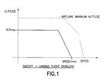
- FIG. 1 is a graph showing a typical airplane flight operating within maximum altitude and speed boundaries and the target flight operating envelope for differential control of flaps in accordance with embodiments of the system disclosed herein.
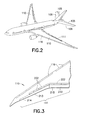
- FIG. 2 is an illustration showing an overall view of typical airplane controllable camber surfaces on wing and empennage.
- FIG. 3 is an illustration showing a detailed view of wing controllable camber surfaces, including inboard and outboard flaps.
- FIG. 4 is an illustration showing a detailed view of wing controllable camber surfaces, including inboard, outboard and midspan flaps.
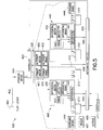
- FIG. 5 is an illustration depicting an embodiment of a control system operatively connected to and controlling inboard and outboard flap positions during take-off and landing.
- FIG. 6 is an illustration depicting an embodiment of a control system operatively connected to and controlling inboard, outboard and midspan flap positions during take-off and landing.
- FIG. 7 is an illustration of steps for activating motors, brakes and other parts within primary and differential control devices, in order to achieve differential motion of inboard flaps with respect to outboard flaps.
- FIG. 8 is an illustration of steps for activating motors, brakes and other parts within primary and differential control devices, in order to achieve differential motion of inboard flaps and midspan flaps with respect to outboard flaps.
- FIG. 9 is a block diagram depicting a control law for determining movement amount for controlling inboard and outboard flaps based on a flap lever position during take-off and landing.
- FIG. 10 is a block diagram depicting a control law for determining movement amount for controlling inboard, outboard and midspan flaps based on a flap lever position during take-off and landing.
- an exemplary embodiment is intended to operate within the flight envelope defined by the boundary parameters shown.
- the maximum altitude boundary of the flight envelope is the maximum altitude at which flaps would be deployed to increase lift for take-off and landing (ALTmax).
- the minimum altitude boundary is the altitude of the lowest airport the airplane is designed to operate from.
- the maximum speed boundaries within which the system operates is the maximum speed at which flaps would be deployed for takeoff or landing (SPEEDmax).
- SPEEDmax maximum speed at which flaps would be deployed for takeoff or landing
- the minimum speed boundary is zero knots.
- an overall view of a typical commercial airliner shows its controllable camber surfaces including wing 110, wing trailing-edge devices 111, wing leading-edge devices 116, horizontal tail 106 and tail elevators 105.
- This exemplary embodiment is operative to adjust trailing devices 111 to provide optimal settings in the take-off and landing flight envelope.
- a detailed view shows typical wing camber surfaces including wing 110, wing trailing-edge devices 111, and wing leading-edge devices 116.
- the wing trailing-edge devices 111 include inboard trailing-edge flap 212, inboard roll-control flap device 215, outboard trailing-edge flap 213, outboard roll-control flap device 214, and spoilers 222.
- Camber characteristics of the flap devices 212 and 213 and can be adjusted appropriately during take-off and landing to provide optimal efficiency.
- a detailed view shows an alternate wing 310 embodiment showing alternate wing trailing edge devices 311.
- the wing trailing-edge devices 311 include outboard trailing-edge flap 313, midspan trailing-edge flap 316 and inboard trailing-edge flap 312, as well as inboard roll-control flap device 315 and outboard roll-control flap device 314.
- the camber characteristics of the flap devices 312, 313 and 316 can be adjusted appropriately during take-off and landing to provide optimal efficiency.
- a control system 420 configured to implement the control law of the present application, for moving inboard and outboard flaps differentially within the take-off and landing flight envelope is shown and described.
- the control system 420 may be implemented, for example, to control a wing as depicted in FIG. 3 .
- Controller 423 may be an electronic or other type of control device containing memory and a microprocessor, for accepting input, processing the input, and providing output commands in response to the inputs, for controlling the motors and other devices which will adjust flap position. Controller 423 is operatively coupled to a central control device 430 and two differential control devices 440. Controller 423 receives automatic inputs 425 and operator inputs 424. Operator inputs can include a flap lever position reading 462, determined from flap lever 460. Automatic inputs can include left differential position 464, right differential position 466 and inboard flap position 468. Left differential position 464 and right differential position 466 are absolute values - that is, they represent an absolute amount that differential motors 455 have moved from a "zero" position.
- rotary sensors such as a rotary variable differential transformer, a resolver, or an optical encoder.
- Automatic inputs may also include airplane weight 467, airplane altitude 469 and airspeed 471.
- controller 423 will determine optimal movements for inboard flaps 212 and outboard flaps 213 and direct the central control device 430 and differential control devices 440 appropriately.
- Central control device 430 has primary motor 451 and alternate motor 452, each of which power a drive link 453.
- Central control device 430 also has primary brake 431 and alternate brake 432 which selectively inhibit the motion of the primary motor 451 and alternate motor 452, respectively.
- Power provided to the drive link 453 may also be transferred through differential 441 to the outboard flaps 213.
- Differential control devices 440 are provided which provide differential control for outboard flaps 213.
- Differential control device 440 preferably has a differential motor 455, differential brake 442, a differential 441, and range limiter 443.
- Range limiter 443 might be a physical device, or may be implemented in programmed instructions in controller 423 or in another control device.
- the differential motor 455 provides power to the differential 441 to create differential motion between the inboard and outboard flaps.
- the differential 441 can receive power from both differential motor 455 and drive link 453, and can distribute power to inboard flap 212, outboard flap 213, or both.
- differential 441 can include a planetary gear device or other suitable mechanical differential, or similar hydraulic or electrical device, depending on the nature of the drive link 453.
- a range limiter 443 prevents differential motion of the outboard flaps 213 relative to the inboard flaps 212 past certain fixed bounds. As stated above, this range limiting function may be implemented entirely or partially within the programming of controller 423 or other programmable control device, and need not be implemented as a separate physical structure.
- the differential brake 442 When the differential brake 442 is engaged, it prevents differential motion of the outboard flaps 213 with respect to inboard flaps 212 such that the differential control device 440 acts as a pass through gearbox with a fixed gear ratio. In this situation, inboard flaps 212 and outboard flaps 213 travel by the same amount.
- differential motor 455 can be utilized to move outboard flaps 213 differentially relative to inboard flaps 212. If primary motor 451 is providing power to drive link 453 in one direction and differential motor 455 is providing power in the same direction, then the outboard flap 213 will travel in the same direction, but farther than inboard flaps 212. If, on the other hand, primary motor 451 is providing power to drive link 453 in one direction and differential motor 455 is providing power in the opposite direction, then the outboard flap 213 will travel in the same direction, but not as far as the inboard flap 212.
- An outboard brake 444 can be used to prevent motion of the outboard section of the drive link 453, and therefore prevent motion of the outboard flaps 213 while the inboard flaps 212 are in motion. If outboard brake 444 is engaged while differential brake is disengaged and the differential motor is engaged, differential motor 455 will move inboard flaps 212 while outboard flaps 213 remain stationary. While outboard brake 444 is shown in a physically separate location, outboard brake 444 may be included within differential control device 440.
- the differential motor 455 may be a lower horsepower motor than the primary 451 and/or alternate motor 452.
- the primary motor 451 may be a high horsepower hydraulic motor, having a horsepower of 40Hp while the differential motor 455 may be a much lower horsepower electric motor of 3 Hp. It should be recognized that other types of motors may be used, and that the types described are merely exemplary. The goal of using motors having different horsepower amounts is to reduce space occupied and weight of structures on the wing.
- a control system 600 configured to implement the control law of the present application, for moving inboard, outboard and midspan flaps differentially within the take-off and landing flight envelope is shown and described.
- the control system 600 may be implemented, for example, to control a wing as depicted in FIG. 4 .
- Controller 623 may be an electronic or other type of control device containing memory and a microprocessor, for accepting input, processing the input, and providing output commands in response to the inputs, for controlling the motors and other devices which will adjust flap position.
- Controller 623 is operatively coupled to a central control device 630, midspan differential control devices 640 and outboard differential control devices 650. Controller 623 receives automatic inputs 625 and operator inputs 624. Operator inputs 625 can include a flap lever position reading 662, determined from flap lever 660. Automatic inputs can include left outboard differential position 676, right outboard differential position 680, left midspan differential position 677, right midspan differential position 679 and inboard flap position 678. As with the embodiment described with respect to FIG. 5 , the differential positions 676, 677, 679, 680 represent absolute movement of the midspan and outboard differential motors 644, 655 from an initial "zero" position.
- rotary sensors such as a rotary variable differential transformer, a resolver, or an optical encoder.
- Automatic inputs may also include airplane weight 667, airplane altitude 669 and airspeed 671.
- controller 623 will determine optimal movements for inboard flaps 312, outboard flaps 313 and midspan flaps 316 and direct the central control device 630, outboard differential control devices 640 and midspan differential control devices 650 appropriately.
- Central control device 630 has primary motor 653 and alternate motor 654, each of which power a drive link 645.
- Central control device 630 also has primary brake 631 and alternate brake 632 which selectively inhibit the motion of the primary motor 633 and alternate motor 634, respectively.
- Power provided to the drive link 645 may also be transferred to midspan flaps 316 and outboard flaps 313.
- Midspan differential control devices 650 are provided which provide differential control for midspan flaps 316 relative to inboard flaps 312.
- Midspan differential control device 650 preferably has a midspan differential motor 655, midspan differential brake 652, midspan differential 651, and midspan range limiter 653.
- Midspan range limiter 653 might be a physical device, or may be implemented in programmed instructions in controller 623 or in another control device.
- Midspan differential motor 655 provides power to the midspan differential 651 to create differential motion between the inboard flaps 312 and the midspan flaps 316. This differential motion may be transferred to outboard flaps 313 depending on the state of outboard control device 640. This will be described in further detail below, with respect to FIG. 10 .
- Midspan differential 651 can receive power from both midspan differential motor 655 and drive link 645, and can distribute power to inboard flap 312, outboard flap 313, midspan flaps 316, or any combination thereof.
- midspan differential 651 can include a planetary gear device or other suitable mechanical differential, or similar hydraulic or electrical device, depending on the nature of the drive link 653.
- Midspan range limiter 653 prevents differential motion of the midspan flaps 316 relative to the inboard flaps 312 and/or outboard flaps 313 past certain fixed bounds. As stated above, this range limiting function may be implemented entirely or partially within the programming of controller 623 or other programmable control device, and need not be implemented as a separate physical structure.
- midspan differential brake 652 When the midspan differential brake 652 is engaged, it prevents differential motion of the midspan flaps 316 with respect to inboard flaps 312 such that the midspan differential control device 650 acts as a pass through gearbox with a fixed gear ratio. In this situation, midspan flaps 316 and inboard flaps 312 travel by the same amount. Engagement of midspan differential brake 652 does not necessitate that outboard flaps 313 travel by the same amount as midspan flaps 316 or inboard flaps 312.
- midspan differential motor 655 can be utilized to move midspan flaps 316 and inboard flaps 312 differentially. If primary motor 633 is providing power to drive link 645 in one direction and midspan differential motor 655 is providing power in the same direction, then the midspan flap 316 will travel in the same direction, but farther than inboard flaps 312. If, on the other hand, primary motor 633 is providing power to drive link 645 in one direction and midspan differential motor 655 is providing power in the opposite direction, then the midspan flap 316 will travel in the same direction, but not as far as the inboard flap 312.
- Outboard differential control devices 640 are provided which provide differential control for outboard flaps 313.
- Outboard differential control device 640 preferably has an outboard differential motor 644, outboard differential brake 642, outboard differential 641, and outboard range limiter 643.
- Outboard range limiter 643 might be a physical device, or may be implemented in programmed instructions in controller 623 or in another control device
- Outboard differential motor 644 provides power to the outboard differential 641 to create differential motion between the midspan flap 316 and outboard flaps 313.
- the outboard differential 641 can receive power from both outboard differential motor 644 and drive link 645, and can distribute power to midspan differential 641, outboard flap 313 or both.
- outboard differential 641 can include a planetary gear device or other suitable mechanical differential, or similar hydraulic or electrical device, depending on the nature of the drive link 645.
- An outboard range limiter 643 prevents differential motion of the outboard flaps 313 relative to the midspan flaps 316 past certain fixed bounds.
- this range limiting function may be implemented entirely or partially within the programming of controller 623 or other programmable control device, and need not be implemented as a separate physical structure. Because midspan differential 651 can provide power to outboard flaps 313, motion of outboard flaps 313 will be dependent on the interaction between midspan differential control device 650 and primary control device 630, as described above.
- the outboard differential brake 642 When the outboard differential brake 642 is engaged, it prevents differential motion of the outboard flaps 313 with respect to midspan flaps 316 such that the outboard differential control device 640 acts as a pass through gearbox with a fixed gear ratio. In this situation, midspan flaps 316 and outboard flaps 313 travel by the same amount.
- outboard differential motor 644 can be utilized to move outboard flaps 313 differentially.
- Outboard flaps 313 can receive power both from midspan differential 651 and from outboard differential motor 644.
- An outboard brake 646 can be used to prevent motion of the outboard section of the drive link 645, and therefore prevent motion of the outboard flaps 313 while the inboard flaps 312 and/or midspan flaps 316 are in motion. If outboard brake 646 is engaged while outboard differential brake 642 is disengaged and the outboard differential motor 644 is engaged, outboard differential motor 644 can provide power to midspan flap 316 and/or inboard flap 312 while outboard flap 313 remains stationary. While outboard brake 646 is shown in a physically separate location, outboard brake 646 may be included within outboard differential control device 640.
- the midspan differential motor 655 and/or outboard differential motor 644 may be a lower horsepower motor than the primary 633 and/or alternate motor 634.
- the primary motor 633 may be a high horsepower hydraulic motor, having a horsepower of 40Hp while the midspan differential motor 655 and/or outboard differential motor 644 may be a much lower horsepower electric motor of 3 Hp.
- other types of motors may be used, and that the types described are merely exemplary. The goal of using motors having different horsepower amounts is to reduce space occupied and weight of structures on the wing.
- FIG. 7 an illustration of the steps performed for controlling outboard and inboard flaps differentially is shown. These steps may be implemented, for example, on a wing and control system as depicted in FIGS. 3 and 5 , respectively.
- the different parts are activated to bring inboard flaps 212 and outboard flaps 213 to their optimal positions.
- differential motor 455 may be activated.
- differential control devices 440 on each wing may be controlled separately, to move left and right outboard flap surfaces to different positions.
- a flap lever position changes, and provides a signal 462 to controller 423 indicating that a change in flap position is desired.
- flap lever signal 462 may come from other structures or devices, such as other physical devices used to manually command flaps, or from an automatic system which can automatically command flap position (for example, from "flap load relief” system which automatically readjusts flaps if pilot accelerates to an airspeed greater than the flap is designed for).
- step 704 new desired (or “ideal”) flap positions for inboard and outboard flaps are determined from a lookup table.
- the lookup table accepts flap lever position signal (or “desired position signal”) 462 as input, and may also accept airplane weight, airplane altitude and/or airspeed to more precisely determine ideal flap positions.
- flap lever position signal or “desired position signal”
- Other variables that can assist in determining optimal flap surface positions may be used as inputs to the lookup table—the lookup table serves the purpose of providing ideal flap surface positions, given flap lever position during takeoff and landing. Other methods of determining ideal flap positions may also be used.
- step 706 the current positions of left outboard differential motor, right outboard differential motor, and primary motor are determined.
- a gauge or other device for determining these positions may be used.
- step 708 a move increment for each motor is determined. This will be described in further detail with regard to figure 9 .
- step 710 all motors are commanded to zero speed.
- step 712 primary brake, left differential brake, right differential brake and outboard brake are released, in order to allow primary motor to power drive link 453, and to allow outboard flaps 213 to move with respect to inboard flaps 212.
- step 714 left outboard motor, right outboard motor, and primary motors are commanded to move by the amount determined in step 708.
- step 716 primary brake, left differential brake, right differential brake and outboard brake are re-engaged, preventing motion of all flap surfaces.
- FIG. 8 an illustration of the steps performed by a control law for controlling outboard, midspan and inboard flaps differentially is shown. These steps may be implemented on a wing and control system, for example, as depicted in FIGS. 4 and 6 , respectively.
- the different parts are activated to bring inboard flaps 312, midspan flaps 316 and outboard flaps 313 to their optimal positions.
- differential motors 655, 644 may be activated.
- a flap lever position changes, and provides a signal 662 to controller 623, indicating that a change in flap position is desired.
- flap lever signal 662 may come from other structures or devices, such as other physical devices used to manually command flaps, or from an automatic system which can automatically command flap position.
- step 804 new desired (or “ideal”) flap positions for inboard, midspan and outboard flaps are determined from a lookup table.
- the lookup table accepts flap lever position signal (or “desired position signal”) 662 as input, and may also accept airplane weight, airplane altitude and/or airspeed to more precisely determine ideal flap positions.
- flap lever position signal or “desired position signal”
- Other variables that can assist in determining optimal flap surface positions may be used as inputs to the lookup table—the lookup table serves the purpose of providing ideal flap surface positions, given flap lever position during takeoff and landing. Other methods of determining ideal flap positions may also be used.
- step 806 the current positions of left outboard differential motor, right outboard differential motor, left midspan motor, right midspan motor and primary motor are determined.
- a gauge or other device for determining these positions may be used.
- step 808 a move increment for each motor is determined. This will be described in further detail with regard to figure 10 .
- step 810 all motors are commanded to zero speed.
- step 812 primary brake, left outboard differential brake, right outboard differential brake, left midspan differential brake, right midspan differential brake and outboard brake are released, in order to allow primary motor to power drive link, and to allow outboard flaps, midspan flaps and inboard flaps to move with respect to each other.
- step 814 left outboard differential motor, right outboard differential motor, left midspan differential motor, right midspan differential motor, and primary motors are commanded to move by the amount determined in step 808.
- step 816 primary brake, left outboard differential brake, right outboard differential brake, left midspan differential brake, right midspan differential brake and outboard brake are re-engaged, preventing motion of all flap surfaces.
- control laws for determining displacement amounts for outboard and inboard flaps, and midspan flaps if present are disclosed.
- the control laws described herein are designed to be implemented as computer instructions carried out by controller 423 or controller 623.
- the control laws determine an amount of displacement that each of a primary motor, midspan motor, and/or outboard motor should provide to outboard, midspan, and inboard flaps.
- control laws are designed to provide an appropriate amount of movement to each motor, taking into account the fact that activation of each of the motors may move more than one flap.
- primary motor may cause inboard and outboard flaps to move, and may cause midspan flaps to move by a certain amount as well. More information relating to motion provided by each motor to each flap is described in more detail below, with respect to FIGS. 9 and 10 .
- control law contemplates that inputs will be inboard flap position and midspan and outboard differential position, other inputs to the control law could be provided. For example, instead of calculating the current outboard position 516, 1008 or current midspan position 1004, those positions could be measured and provided to the control law directly.
- FIG. 9 a functional block diagram depicting control logic for determining displacement amounts for inboard flaps 212 and outboard flaps 213 is shown.
- This functional block diagram may be used for wing, control system, and method depicted in FIGS. 3 , 5 and 7 , respectively.
- Inputs to the block diagram include a flap lever position 462, a current differential position 464, 466, and a current inboard flap position 468.
- the current flap lever position 462 is provided to a lookup table 508, which outputs an ideal outboard position 510 and ideal inboard flap position 512.
- airplane weight 467, airplane altitude 469, and/or airspeed 471 may also be provided to the lookup table 508, which will provide appropriate outputs.
- Current inboard flap position 468 is subtracted from current right differential position 464 at 514 to determine current right outboard flap position 516.
- the current right outboard flap position 516 is subtracted from ideal right outboard position 510 from the lookup table 508 at 518 to determine the total amount the right outboard flap will move 520.
- the total amount inboard flap will move 524 will be subtracted from the total amount right outboard flap will move 520 at 528.
- the output is commanded to the right differential motor at 530.
- differential motor 455 If differential motor 455 is activated while primary motor 451 is activated, power will be provided to the outboard flaps 213 by both motors. Therefore, if it is desirable to move outboard flaps 213 by a displacement amount which is greater than the displacement amount of inboard flaps 212, differential motor 455 may be activated in the same direction as, and during activation of primary motor 451.
- differential motor 455 may be activated in the opposite direction as, but still during the activation of, the primary motor 451.
- differential motor 455 need not be activated.
- differential brake 442 may be set in order to prevent differential motion of outboard flaps 213 with respect to inboard flaps 212. In this case, only primary motor 451 will be required to be activated, and it will be used to move both inboard flaps 212 and outboard flaps 213 by the same amount.
- motors 455 and 451 need not be activated simultaneously in order to provide differential motion to inboard, midspan and outboard flaps.
- Differential brakes 442 may be set to allow any or all surfaces to move together. Subsequently, differential motor 455 may be activated to provide differential motion to flaps 213.
- FIG. 10 a functional block diagram depicting control logic for determining displacement amounts for inboard flaps 312, midspan flaps 316 and outboard flaps 313 is shown.
- This functional block diagram may be used for wing, control system, and method depicted in FIGS. 4 , 6 and 8 , respectively.
- Inputs to the block diagram include a flap lever position 662, current outboard differential position 680, 676, current midspan differential position 677, 679, and a current inboard flap position 678
- "differential position” represents an absolute measurement of the motion of the corresponding differential motor, from a zero position.
- Current inboard flap position is added to current right midspan differential position at 1002, which results in current right midspan position 1004.
- Current right midspan position is added to current right outboard differential position at 1006, to provide current right outboard position 1008.
- Current right outboard position 1008 is subtracted from ideal right outboard position 1010 from the lookup table 1001 at 1012 to determine total amount right outboard flap will move 1014.
- Total amount right midspan flap will move 1020 will be subtracted from total amount right outboard flap will move 1014 at 1030 and the result will be commanded to right outboard differential motor at 485.
- midspan differential motor 655 is activated while primary motor 633 is activated, power will be provided to the midspan flaps 316 by both motors. Therefore, if it is desirable to move midspan flaps 316 by a displacement amount which is greater than the displacement amount of inboard flaps 312, midspan differential motor 655 may be activated in the same direction as, and during activation of primary motor 633.
- midspan differential motor 655 may be activated in the opposite direction as, but still during the activation of, the primary motor 633.
- midspan differential motor 655 need not be activated. Instead, midspan differential brake 652 may be set in order to prevent differential motion of midspan flaps 316 with respect to inboard flaps 312. In this case, only primary motor 633 will be required to be activated, and it will be used to move both inboard flaps 312 and midspan flaps 316 by the same amount.
- outboard differential motor 644 For motion of outboard flaps 313, outboard differential motor 644 provides motion with respect to motion provided by midspan differential 651. Therefore, if outboard differential motor 644 is activated while midspan flaps 316 are moving, outboard flaps 313 will be provided with power by both midspan differential 651 and by outboard differential motor 644, and outboard flaps 313 will move differentially with respect to midspan flaps 316.
- outboard differential motor 644 may be activated in the same direction as motion of the midspan flaps 316.
- outboard differential motor 644 may be activated in the opposite direction as motion of the midspan flaps 316.
- outboard differential motor 644 need not be activated. Instead, outboard differential brake 642 may be set in order to prevent differential motion of outboard flaps 313 with respect to midspan flaps 316.
- motors 633, 644 and 655 need not be activated simultaneously in order to provide differential motion to inboard, midspan and outboard flaps.
- Differential brakes 652, 642 may be set to allow any or all surfaces to move together. Subsequently, differential motors 644, 655 may be activated to provide differential motion to flap surfaces 316, 312.
Applications Claiming Priority (1)
| Application Number | Priority Date | Filing Date | Title |
|---|---|---|---|
| US12/968,383 US9327824B2 (en) | 2010-12-15 | 2010-12-15 | Adjustment of wings for variable camber for optimum take-off and landing |
Publications (3)
| Publication Number | Publication Date |
|---|---|
| EP2465770A2 true EP2465770A2 (de) | 2012-06-20 |
| EP2465770A3 EP2465770A3 (de) | 2017-07-19 |
| EP2465770B1 EP2465770B1 (de) | 2021-11-10 |
Family
ID=45349404
Family Applications (1)
| Application Number | Title | Priority Date | Filing Date |
|---|---|---|---|
| EP11193899.9A Active EP2465770B1 (de) | 2010-12-15 | 2011-12-15 | Anpassung von Flügeln für variable Wölbung zur optimalen Start- und Landekonfiguration |
Country Status (5)
| Country | Link |
|---|---|
| US (1) | US9327824B2 (de) |
| EP (1) | EP2465770B1 (de) |
| JP (1) | JP2012126389A (de) |
| CN (1) | CN102530241B (de) |
| CA (1) | CA2756781C (de) |
Cited By (9)
| Publication number | Priority date | Publication date | Assignee | Title |
|---|---|---|---|---|
| EP2851284A1 (de) * | 2013-09-24 | 2015-03-25 | The Boeing Company | Variables Wölbklappensystem und Verfahren |
| US9180962B2 (en) | 2013-09-24 | 2015-11-10 | The Boeing Company | Leading edge variable camber system and method |
| US9296475B2 (en) | 2013-09-24 | 2016-03-29 | The Boeing Company | System and method for reducing the stopping distance of an aircraft |
| US9327827B2 (en) | 2013-09-24 | 2016-05-03 | The Boeing Company | Leading and trailing edge device deflections during descent of an aircraft |
| US9656741B2 (en) | 2013-09-24 | 2017-05-23 | The Boeing Company | Control interface for leading and trailing edge devices |
| US9771141B2 (en) | 2013-09-24 | 2017-09-26 | The Boeing Company | Leading edge system and method for approach noise reduction |
| US9821903B2 (en) | 2014-07-14 | 2017-11-21 | The Boeing Company | Closed loop control of aircraft control surfaces |
| EP3476725A1 (de) * | 2017-10-30 | 2019-05-01 | The Boeing Company | Verfahren und systeme zur steuerung der flugzeugflugleistung |
| WO2021094245A1 (de) * | 2019-11-13 | 2021-05-20 | Deutsches Zentrum für Luft- und Raumfahrt e.V. | Verfahren und vorrichtung zum erweitern der flugenveloppe eines verkehrsflugzeugs |
Families Citing this family (11)
| Publication number | Priority date | Publication date | Assignee | Title |
|---|---|---|---|---|
| US20130145743A1 (en) * | 2011-12-08 | 2013-06-13 | Honeywell International Inc. | Case assembly with fuel driven actuation systems |
| CN105008221B (zh) * | 2013-03-06 | 2017-08-08 | 庞巴迪公司 | 飞机的高升力控制方法和系统 |
| US9359065B2 (en) * | 2013-09-24 | 2016-06-07 | The Boeing Company | System and method for optimizing performance of an aircraft |
| US9488130B2 (en) | 2013-10-17 | 2016-11-08 | Honeywell International Inc. | Variable area fan nozzle systems with improved drive couplings |
| US10401875B2 (en) | 2014-07-31 | 2019-09-03 | The Boeing Company | Electronic stopper in actuator control |
| EP3241742B1 (de) * | 2016-05-06 | 2018-12-12 | Airbus Operations S.L. | Flugzeugleitwerk |
| US10279891B2 (en) * | 2016-06-02 | 2019-05-07 | Google Llc | Software controlled stiffening of flexible aircraft |
| US10669014B2 (en) * | 2016-12-02 | 2020-06-02 | The Boeing Company | Differential for control surface actuators |
| CA3053826A1 (en) * | 2018-09-04 | 2020-03-04 | Bombardier Inc. | High-lift actuation system with clutch architecture |
| EP3650354B1 (de) * | 2018-11-12 | 2021-11-03 | Ratier-Figeac SAS | Schubregelungsanordnung |
| CN113609582B (zh) * | 2021-07-30 | 2024-02-20 | 北京航空航天大学 | 一种满足机构运动和缝道参数的增升装置位置设计方法 |
Citations (1)
| Publication number | Priority date | Publication date | Assignee | Title |
|---|---|---|---|---|
| US7494094B2 (en) | 2004-09-08 | 2009-02-24 | The Boeing Company | Aircraft wing systems for providing differential motion to deployable lift devices |
Family Cites Families (17)
| Publication number | Priority date | Publication date | Assignee | Title |
|---|---|---|---|---|
| US4106730A (en) * | 1976-10-01 | 1978-08-15 | The Boeing Company | Engine out control system for STOL aircraft |
| DE3530865A1 (de) * | 1985-08-29 | 1987-03-12 | Messerschmitt Boelkow Blohm | Antriebs- und fuehrungsvorrichtung fuer ein an einem flugzeugtragfluegel angeordnetes klappensystem |
| JP3012644B1 (ja) * | 1999-03-18 | 2000-02-28 | 株式会社コミュータヘリコプタ先進技術研究所 | サ―ボアクチュエ―タ装置および航空機操縦制御装置 |
| US6465902B1 (en) * | 2001-04-18 | 2002-10-15 | The United States Of America As Represented By The Secretary Of The Navy | Controllable camber windmill blades |
| GB0127254D0 (en) * | 2001-11-13 | 2002-01-02 | Lucas Industries Ltd | Aircraft flight surface control system |
| DE10313728B4 (de) * | 2003-03-27 | 2011-07-21 | Airbus Operations GmbH, 21129 | Klappensystem am Tragflügel eines Starrflügel-Flugzeuges |
| US20090206197A1 (en) * | 2003-04-14 | 2009-08-20 | Curtiss-Wright Controls, Inc. | Actuator and flap arrangement with actuator interconnection |
| DE10361891A1 (de) * | 2003-12-23 | 2005-08-04 | Airbus Deutschland Gmbh | Vorrichtung zur Ansteuerung und Verstellung von Klappen an Flugzeugtragflächen |
| US7338018B2 (en) * | 2005-02-04 | 2008-03-04 | The Boeing Company | Systems and methods for controlling aircraft flaps and spoilers |
| US7600715B2 (en) * | 2005-03-25 | 2009-10-13 | Nabtesco Corporation | Local backup hydraulic actuator for aircraft control systems |
| US7556224B2 (en) * | 2005-12-27 | 2009-07-07 | Honeywell International Inc. | Distributed flight control surface actuation system |
| DE102006058650B4 (de) | 2006-12-11 | 2009-11-19 | Eads Deutschland Gmbh | Tragflügel eines Flugzeugs |
| US7641152B2 (en) | 2007-04-13 | 2010-01-05 | The Boeing Company | Dynamic adjustment of wing surfaces for variable camber |
| DE102007063157A1 (de) | 2007-12-30 | 2009-07-09 | Airbus Deutschland Gmbh | System zur Betätigung von zumindest einer Stellklappe eines Flugzeugs sowie ein Verfahren zur Überprüfung des Systems |
| FR2939528B1 (fr) | 2008-12-08 | 2011-02-11 | Airbus France | Dispositif et procede de generation automatique d'un ordre de commande d'une gouverne d'aeronef |
| US8235327B2 (en) * | 2009-03-18 | 2012-08-07 | Insitu, Inc. | Adjustable servomechanism assemblies and associated systems and methods |
| DE102009017653A1 (de) * | 2009-04-16 | 2010-10-21 | Airbus Deutschland Gmbh | Hochauftriebssystem eines Flugzeugs, Flugzeugsystem und Propeller-Flugzeug mit einem Hochauftriebssystem |
-
2010
- 2010-12-15 US US12/968,383 patent/US9327824B2/en active Active
-
2011
- 2011-10-31 CA CA2756781A patent/CA2756781C/en active Active
- 2011-12-08 JP JP2011268801A patent/JP2012126389A/ja active Pending
- 2011-12-15 EP EP11193899.9A patent/EP2465770B1/de active Active
- 2011-12-15 CN CN201110434588.8A patent/CN102530241B/zh active Active
Patent Citations (2)
| Publication number | Priority date | Publication date | Assignee | Title |
|---|---|---|---|---|
| US7494094B2 (en) | 2004-09-08 | 2009-02-24 | The Boeing Company | Aircraft wing systems for providing differential motion to deployable lift devices |
| US7726610B2 (en) | 2004-09-08 | 2010-06-01 | The Boeing Company | Systems and methods for providing differential motion to wing high lift device |
Cited By (12)
| Publication number | Priority date | Publication date | Assignee | Title |
|---|---|---|---|---|
| EP2851284A1 (de) * | 2013-09-24 | 2015-03-25 | The Boeing Company | Variables Wölbklappensystem und Verfahren |
| US20150083852A1 (en) * | 2013-09-24 | 2015-03-26 | The Boeing Company | Variable camber flap system and method |
| US9180962B2 (en) | 2013-09-24 | 2015-11-10 | The Boeing Company | Leading edge variable camber system and method |
| US9193440B2 (en) | 2013-09-24 | 2015-11-24 | The Boeing Company | Variable camber flap system and method |
| US9296475B2 (en) | 2013-09-24 | 2016-03-29 | The Boeing Company | System and method for reducing the stopping distance of an aircraft |
| US9327827B2 (en) | 2013-09-24 | 2016-05-03 | The Boeing Company | Leading and trailing edge device deflections during descent of an aircraft |
| US9656741B2 (en) | 2013-09-24 | 2017-05-23 | The Boeing Company | Control interface for leading and trailing edge devices |
| US9771141B2 (en) | 2013-09-24 | 2017-09-26 | The Boeing Company | Leading edge system and method for approach noise reduction |
| US9821903B2 (en) | 2014-07-14 | 2017-11-21 | The Boeing Company | Closed loop control of aircraft control surfaces |
| EP3476725A1 (de) * | 2017-10-30 | 2019-05-01 | The Boeing Company | Verfahren und systeme zur steuerung der flugzeugflugleistung |
| US10793260B1 (en) | 2017-10-30 | 2020-10-06 | The Boeing Company | Methods and systems for controlling aircraft flight performance |
| WO2021094245A1 (de) * | 2019-11-13 | 2021-05-20 | Deutsches Zentrum für Luft- und Raumfahrt e.V. | Verfahren und vorrichtung zum erweitern der flugenveloppe eines verkehrsflugzeugs |
Also Published As
| Publication number | Publication date |
|---|---|
| US9327824B2 (en) | 2016-05-03 |
| EP2465770A3 (de) | 2017-07-19 |
| EP2465770B1 (de) | 2021-11-10 |
| CA2756781C (en) | 2016-05-31 |
| US20120153085A1 (en) | 2012-06-21 |
| CN102530241A (zh) | 2012-07-04 |
| JP2012126389A (ja) | 2012-07-05 |
| CA2756781A1 (en) | 2012-06-15 |
| CN102530241B (zh) | 2016-08-24 |
Similar Documents
| Publication | Publication Date | Title |
|---|---|---|
| US9327824B2 (en) | Adjustment of wings for variable camber for optimum take-off and landing | |
| EP2851285B1 (de) | Variables eintrittskantenkammersystem und verfahren | |
| EP1786667B2 (de) | Systeme und verfahren zur bereitstellung von differenzieller bewegung für flügelhochauftriebsvorrichtungen | |
| EP2851284B1 (de) | Variables Wölbklappensystem und Verfahren | |
| US7556224B2 (en) | Distributed flight control surface actuation system | |
| EP2851287B1 (de) | Hinterkantenaktuatorsystem und -verfahren | |
| US7701161B2 (en) | Motor balanced active user interface assembly | |
| EP2524865A1 (de) | Flugzeugflügelanordnung | |
| US20170283041A1 (en) | Aircraft | |
| EP2599712B1 (de) | Aerodynamische Tragflächenbelastungsverteilungssteuerung | |
| EP3825227B1 (de) | Minispoiler zur verbesserung der wirksamkeit von quersteuerungsflächen von flugzeugtragflächen | |
| WO2010119280A1 (en) | High lift devices for aircraft | |
| CN112238934B (zh) | 飞机、自动速度制动控制系统和用于控制飞机阻力的方法 | |
| US11396363B2 (en) | Open and closed control of actuators, which drive aerodynamic control surfaces of an aircraft | |
| CN109328163B (zh) | 用于展开相邻的后缘襟翼的方法和系统 | |
| US20190256195A1 (en) | Reducing gust loads acting on an aircraft | |
| US20220097827A1 (en) | Aircraft pitch control system with electronically geared elevator | |
| KR101885663B1 (ko) | 기계식 조종장치를 백업으로 갖는 전자식 비행제어 시스템 |
Legal Events
| Date | Code | Title | Description |
|---|---|---|---|
| PUAI | Public reference made under article 153(3) epc to a published international application that has entered the european phase |
Free format text: ORIGINAL CODE: 0009012 |
|
| 17P | Request for examination filed |
Effective date: 20111215 |
|
| AK | Designated contracting states |
Kind code of ref document: A2 Designated state(s): AL AT BE BG CH CY CZ DE DK EE ES FI FR GB GR HR HU IE IS IT LI LT LU LV MC MK MT NL NO PL PT RO RS SE SI SK SM TR |
|
| AX | Request for extension of the european patent |
Extension state: BA ME |
|
| PUAL | Search report despatched |
Free format text: ORIGINAL CODE: 0009013 |
|
| AK | Designated contracting states |
Kind code of ref document: A3 Designated state(s): AL AT BE BG CH CY CZ DE DK EE ES FI FR GB GR HR HU IE IS IT LI LT LU LV MC MK MT NL NO PL PT RO RS SE SI SK SM TR |
|
| AX | Request for extension of the european patent |
Extension state: BA ME |
|
| RIC1 | Information provided on ipc code assigned before grant |
Ipc: B64C 9/20 20060101AFI20170613BHEP |
|
| STAA | Information on the status of an ep patent application or granted ep patent |
Free format text: STATUS: EXAMINATION IS IN PROGRESS |
|
| 17Q | First examination report despatched |
Effective date: 20190131 |
|
| STAA | Information on the status of an ep patent application or granted ep patent |
Free format text: STATUS: EXAMINATION IS IN PROGRESS |
|
| GRAP | Despatch of communication of intention to grant a patent |
Free format text: ORIGINAL CODE: EPIDOSNIGR1 |
|
| STAA | Information on the status of an ep patent application or granted ep patent |
Free format text: STATUS: GRANT OF PATENT IS INTENDED |
|
| INTG | Intention to grant announced |
Effective date: 20210210 |
|
| GRAJ | Information related to disapproval of communication of intention to grant by the applicant or resumption of examination proceedings by the epo deleted |
Free format text: ORIGINAL CODE: EPIDOSDIGR1 |
|
| STAA | Information on the status of an ep patent application or granted ep patent |
Free format text: STATUS: EXAMINATION IS IN PROGRESS |
|
| GRAP | Despatch of communication of intention to grant a patent |
Free format text: ORIGINAL CODE: EPIDOSNIGR1 |
|
| STAA | Information on the status of an ep patent application or granted ep patent |
Free format text: STATUS: GRANT OF PATENT IS INTENDED |
|
| INTC | Intention to grant announced (deleted) | ||
| INTG | Intention to grant announced |
Effective date: 20210602 |
|
| GRAS | Grant fee paid |
Free format text: ORIGINAL CODE: EPIDOSNIGR3 |
|
| GRAA | (expected) grant |
Free format text: ORIGINAL CODE: 0009210 |
|
| STAA | Information on the status of an ep patent application or granted ep patent |
Free format text: STATUS: THE PATENT HAS BEEN GRANTED |
|
| AK | Designated contracting states |
Kind code of ref document: B1 Designated state(s): AL AT BE BG CH CY CZ DE DK EE ES FI FR GB GR HR HU IE IS IT LI LT LU LV MC MK MT NL NO PL PT RO RS SE SI SK SM TR |
|
| REG | Reference to a national code |
Ref country code: GB Ref legal event code: FG4D |
|
| REG | Reference to a national code |
Ref country code: AT Ref legal event code: REF Ref document number: 1445872 Country of ref document: AT Kind code of ref document: T Effective date: 20211115 Ref country code: CH Ref legal event code: EP |
|
| REG | Reference to a national code |
Ref country code: DE Ref legal event code: R096 Ref document number: 602011072075 Country of ref document: DE |
|
| REG | Reference to a national code |
Ref country code: IE Ref legal event code: FG4D |
|
| REG | Reference to a national code |
Ref country code: LT Ref legal event code: MG9D |
|
| REG | Reference to a national code |
Ref country code: NL Ref legal event code: MP Effective date: 20211110 |
|
| REG | Reference to a national code |
Ref country code: AT Ref legal event code: MK05 Ref document number: 1445872 Country of ref document: AT Kind code of ref document: T Effective date: 20211110 |
|
| PG25 | Lapsed in a contracting state [announced via postgrant information from national office to epo] |
Ref country code: RS Free format text: LAPSE BECAUSE OF FAILURE TO SUBMIT A TRANSLATION OF THE DESCRIPTION OR TO PAY THE FEE WITHIN THE PRESCRIBED TIME-LIMIT Effective date: 20211110 Ref country code: LT Free format text: LAPSE BECAUSE OF FAILURE TO SUBMIT A TRANSLATION OF THE DESCRIPTION OR TO PAY THE FEE WITHIN THE PRESCRIBED TIME-LIMIT Effective date: 20211110 Ref country code: FI Free format text: LAPSE BECAUSE OF FAILURE TO SUBMIT A TRANSLATION OF THE DESCRIPTION OR TO PAY THE FEE WITHIN THE PRESCRIBED TIME-LIMIT Effective date: 20211110 Ref country code: BG Free format text: LAPSE BECAUSE OF FAILURE TO SUBMIT A TRANSLATION OF THE DESCRIPTION OR TO PAY THE FEE WITHIN THE PRESCRIBED TIME-LIMIT Effective date: 20220210 Ref country code: AT Free format text: LAPSE BECAUSE OF FAILURE TO SUBMIT A TRANSLATION OF THE DESCRIPTION OR TO PAY THE FEE WITHIN THE PRESCRIBED TIME-LIMIT Effective date: 20211110 |
|
| PG25 | Lapsed in a contracting state [announced via postgrant information from national office to epo] |
Ref country code: IS Free format text: LAPSE BECAUSE OF FAILURE TO SUBMIT A TRANSLATION OF THE DESCRIPTION OR TO PAY THE FEE WITHIN THE PRESCRIBED TIME-LIMIT Effective date: 20220310 Ref country code: SE Free format text: LAPSE BECAUSE OF FAILURE TO SUBMIT A TRANSLATION OF THE DESCRIPTION OR TO PAY THE FEE WITHIN THE PRESCRIBED TIME-LIMIT Effective date: 20211110 Ref country code: PT Free format text: LAPSE BECAUSE OF FAILURE TO SUBMIT A TRANSLATION OF THE DESCRIPTION OR TO PAY THE FEE WITHIN THE PRESCRIBED TIME-LIMIT Effective date: 20220310 Ref country code: PL Free format text: LAPSE BECAUSE OF FAILURE TO SUBMIT A TRANSLATION OF THE DESCRIPTION OR TO PAY THE FEE WITHIN THE PRESCRIBED TIME-LIMIT Effective date: 20211110 Ref country code: NO Free format text: LAPSE BECAUSE OF FAILURE TO SUBMIT A TRANSLATION OF THE DESCRIPTION OR TO PAY THE FEE WITHIN THE PRESCRIBED TIME-LIMIT Effective date: 20220210 Ref country code: NL Free format text: LAPSE BECAUSE OF FAILURE TO SUBMIT A TRANSLATION OF THE DESCRIPTION OR TO PAY THE FEE WITHIN THE PRESCRIBED TIME-LIMIT Effective date: 20211110 Ref country code: LV Free format text: LAPSE BECAUSE OF FAILURE TO SUBMIT A TRANSLATION OF THE DESCRIPTION OR TO PAY THE FEE WITHIN THE PRESCRIBED TIME-LIMIT Effective date: 20211110 Ref country code: HR Free format text: LAPSE BECAUSE OF FAILURE TO SUBMIT A TRANSLATION OF THE DESCRIPTION OR TO PAY THE FEE WITHIN THE PRESCRIBED TIME-LIMIT Effective date: 20211110 Ref country code: GR Free format text: LAPSE BECAUSE OF FAILURE TO SUBMIT A TRANSLATION OF THE DESCRIPTION OR TO PAY THE FEE WITHIN THE PRESCRIBED TIME-LIMIT Effective date: 20220211 Ref country code: ES Free format text: LAPSE BECAUSE OF FAILURE TO SUBMIT A TRANSLATION OF THE DESCRIPTION OR TO PAY THE FEE WITHIN THE PRESCRIBED TIME-LIMIT Effective date: 20211110 |
|
| PG25 | Lapsed in a contracting state [announced via postgrant information from national office to epo] |
Ref country code: SM Free format text: LAPSE BECAUSE OF FAILURE TO SUBMIT A TRANSLATION OF THE DESCRIPTION OR TO PAY THE FEE WITHIN THE PRESCRIBED TIME-LIMIT Effective date: 20211110 Ref country code: SK Free format text: LAPSE BECAUSE OF FAILURE TO SUBMIT A TRANSLATION OF THE DESCRIPTION OR TO PAY THE FEE WITHIN THE PRESCRIBED TIME-LIMIT Effective date: 20211110 Ref country code: RO Free format text: LAPSE BECAUSE OF FAILURE TO SUBMIT A TRANSLATION OF THE DESCRIPTION OR TO PAY THE FEE WITHIN THE PRESCRIBED TIME-LIMIT Effective date: 20211110 Ref country code: EE Free format text: LAPSE BECAUSE OF FAILURE TO SUBMIT A TRANSLATION OF THE DESCRIPTION OR TO PAY THE FEE WITHIN THE PRESCRIBED TIME-LIMIT Effective date: 20211110 Ref country code: DK Free format text: LAPSE BECAUSE OF FAILURE TO SUBMIT A TRANSLATION OF THE DESCRIPTION OR TO PAY THE FEE WITHIN THE PRESCRIBED TIME-LIMIT Effective date: 20211110 Ref country code: CZ Free format text: LAPSE BECAUSE OF FAILURE TO SUBMIT A TRANSLATION OF THE DESCRIPTION OR TO PAY THE FEE WITHIN THE PRESCRIBED TIME-LIMIT Effective date: 20211110 |
|
| REG | Reference to a national code |
Ref country code: CH Ref legal event code: PL |
|
| REG | Reference to a national code |
Ref country code: DE Ref legal event code: R097 Ref document number: 602011072075 Country of ref document: DE |
|
| PG25 | Lapsed in a contracting state [announced via postgrant information from national office to epo] |
Ref country code: MC Free format text: LAPSE BECAUSE OF FAILURE TO SUBMIT A TRANSLATION OF THE DESCRIPTION OR TO PAY THE FEE WITHIN THE PRESCRIBED TIME-LIMIT Effective date: 20211110 |
|
| PLBE | No opposition filed within time limit |
Free format text: ORIGINAL CODE: 0009261 |
|
| STAA | Information on the status of an ep patent application or granted ep patent |
Free format text: STATUS: NO OPPOSITION FILED WITHIN TIME LIMIT |
|
| REG | Reference to a national code |
Ref country code: BE Ref legal event code: MM Effective date: 20211231 |
|
| 26N | No opposition filed |
Effective date: 20220811 |
|
| PG25 | Lapsed in a contracting state [announced via postgrant information from national office to epo] |
Ref country code: LU Free format text: LAPSE BECAUSE OF NON-PAYMENT OF DUE FEES Effective date: 20211215 Ref country code: IE Free format text: LAPSE BECAUSE OF NON-PAYMENT OF DUE FEES Effective date: 20211215 Ref country code: AL Free format text: LAPSE BECAUSE OF FAILURE TO SUBMIT A TRANSLATION OF THE DESCRIPTION OR TO PAY THE FEE WITHIN THE PRESCRIBED TIME-LIMIT Effective date: 20211110 |
|
| PG25 | Lapsed in a contracting state [announced via postgrant information from national office to epo] |
Ref country code: SI Free format text: LAPSE BECAUSE OF FAILURE TO SUBMIT A TRANSLATION OF THE DESCRIPTION OR TO PAY THE FEE WITHIN THE PRESCRIBED TIME-LIMIT Effective date: 20211110 Ref country code: BE Free format text: LAPSE BECAUSE OF NON-PAYMENT OF DUE FEES Effective date: 20211231 |
|
| PG25 | Lapsed in a contracting state [announced via postgrant information from national office to epo] |
Ref country code: LI Free format text: LAPSE BECAUSE OF NON-PAYMENT OF DUE FEES Effective date: 20211231 Ref country code: CH Free format text: LAPSE BECAUSE OF NON-PAYMENT OF DUE FEES Effective date: 20211231 |
|
| PG25 | Lapsed in a contracting state [announced via postgrant information from national office to epo] |
Ref country code: IT Free format text: LAPSE BECAUSE OF FAILURE TO SUBMIT A TRANSLATION OF THE DESCRIPTION OR TO PAY THE FEE WITHIN THE PRESCRIBED TIME-LIMIT Effective date: 20211110 Ref country code: HU Free format text: LAPSE BECAUSE OF FAILURE TO SUBMIT A TRANSLATION OF THE DESCRIPTION OR TO PAY THE FEE WITHIN THE PRESCRIBED TIME-LIMIT; INVALID AB INITIO Effective date: 20111215 Ref country code: CY Free format text: LAPSE BECAUSE OF FAILURE TO SUBMIT A TRANSLATION OF THE DESCRIPTION OR TO PAY THE FEE WITHIN THE PRESCRIBED TIME-LIMIT Effective date: 20211110 |
|
| P01 | Opt-out of the competence of the unified patent court (upc) registered |
Effective date: 20230516 |
|
| PGFP | Annual fee paid to national office [announced via postgrant information from national office to epo] |
Ref country code: GB Payment date: 20231227 Year of fee payment: 13 |
|
| PGFP | Annual fee paid to national office [announced via postgrant information from national office to epo] |
Ref country code: FR Payment date: 20231227 Year of fee payment: 13 |
|
| PG25 | Lapsed in a contracting state [announced via postgrant information from national office to epo] |
Ref country code: MK Free format text: LAPSE BECAUSE OF FAILURE TO SUBMIT A TRANSLATION OF THE DESCRIPTION OR TO PAY THE FEE WITHIN THE PRESCRIBED TIME-LIMIT Effective date: 20211110 |
|
| PGFP | Annual fee paid to national office [announced via postgrant information from national office to epo] |
Ref country code: DE Payment date: 20231229 Year of fee payment: 13 |