EP2465762A1 - Dérailleur de bicyclette et procédé - Google Patents
Dérailleur de bicyclette et procédé Download PDFInfo
- Publication number
- EP2465762A1 EP2465762A1 EP11009869A EP11009869A EP2465762A1 EP 2465762 A1 EP2465762 A1 EP 2465762A1 EP 11009869 A EP11009869 A EP 11009869A EP 11009869 A EP11009869 A EP 11009869A EP 2465762 A1 EP2465762 A1 EP 2465762A1
- Authority
- EP
- European Patent Office
- Prior art keywords
- cage
- chain
- mount
- axis
- front derailleur
- Prior art date
- Legal status (The legal status is an assumption and is not a legal conclusion. Google has not performed a legal analysis and makes no representation as to the accuracy of the status listed.)
- Granted
Links
- 238000000034 method Methods 0.000 title claims description 6
- 238000006073 displacement reaction Methods 0.000 description 2
- 238000012986 modification Methods 0.000 description 2
- 230000004048 modification Effects 0.000 description 2
- 230000004308 accommodation Effects 0.000 description 1
- 230000008878 coupling Effects 0.000 description 1
- 238000010168 coupling process Methods 0.000 description 1
- 238000005859 coupling reaction Methods 0.000 description 1
- 238000010586 diagram Methods 0.000 description 1
- 230000005684 electric field Effects 0.000 description 1
Images


Classifications
-
- B—PERFORMING OPERATIONS; TRANSPORTING
- B62—LAND VEHICLES FOR TRAVELLING OTHERWISE THAN ON RAILS
- B62M—RIDER PROPULSION OF WHEELED VEHICLES OR SLEDGES; POWERED PROPULSION OF SLEDGES OR SINGLE-TRACK CYCLES; TRANSMISSIONS SPECIALLY ADAPTED FOR SUCH VEHICLES
- B62M9/00—Transmissions characterised by use of an endless chain, belt, or the like
- B62M9/04—Transmissions characterised by use of an endless chain, belt, or the like of changeable ratio
- B62M9/06—Transmissions characterised by use of an endless chain, belt, or the like of changeable ratio using a single chain, belt, or the like
- B62M9/10—Transmissions characterised by use of an endless chain, belt, or the like of changeable ratio using a single chain, belt, or the like involving different-sized wheels, e.g. rear sprocket chain wheels selectively engaged by the chain, belt, or the like
- B62M9/12—Transmissions characterised by use of an endless chain, belt, or the like of changeable ratio using a single chain, belt, or the like involving different-sized wheels, e.g. rear sprocket chain wheels selectively engaged by the chain, belt, or the like the chain, belt, or the like being laterally shiftable, e.g. using a rear derailleur
- B62M9/131—Front derailleurs
- B62M9/134—Mechanisms for shifting laterally
- B62M9/1342—Mechanisms for shifting laterally characterised by the linkage mechanisms
-
- B—PERFORMING OPERATIONS; TRANSPORTING
- B62—LAND VEHICLES FOR TRAVELLING OTHERWISE THAN ON RAILS
- B62M—RIDER PROPULSION OF WHEELED VEHICLES OR SLEDGES; POWERED PROPULSION OF SLEDGES OR SINGLE-TRACK CYCLES; TRANSMISSIONS SPECIALLY ADAPTED FOR SUCH VEHICLES
- B62M9/00—Transmissions characterised by use of an endless chain, belt, or the like
- B62M9/04—Transmissions characterised by use of an endless chain, belt, or the like of changeable ratio
- B62M9/06—Transmissions characterised by use of an endless chain, belt, or the like of changeable ratio using a single chain, belt, or the like
- B62M9/10—Transmissions characterised by use of an endless chain, belt, or the like of changeable ratio using a single chain, belt, or the like involving different-sized wheels, e.g. rear sprocket chain wheels selectively engaged by the chain, belt, or the like
- B62M9/12—Transmissions characterised by use of an endless chain, belt, or the like of changeable ratio using a single chain, belt, or the like involving different-sized wheels, e.g. rear sprocket chain wheels selectively engaged by the chain, belt, or the like the chain, belt, or the like being laterally shiftable, e.g. using a rear derailleur
- B62M9/131—Front derailleurs
- B62M9/134—Mechanisms for shifting laterally
- B62M9/1344—Mechanisms for shifting laterally limiting or positioning the movement
-
- Y—GENERAL TAGGING OF NEW TECHNOLOGICAL DEVELOPMENTS; GENERAL TAGGING OF CROSS-SECTIONAL TECHNOLOGIES SPANNING OVER SEVERAL SECTIONS OF THE IPC; TECHNICAL SUBJECTS COVERED BY FORMER USPC CROSS-REFERENCE ART COLLECTIONS [XRACs] AND DIGESTS
- Y10—TECHNICAL SUBJECTS COVERED BY FORMER USPC
- Y10T—TECHNICAL SUBJECTS COVERED BY FORMER US CLASSIFICATION
- Y10T29/00—Metal working
- Y10T29/49—Method of mechanical manufacture
- Y10T29/49826—Assembling or joining
Definitions
- the present invention relates to bicycles and more particularly to a bicycle having a derailleur.
- a derailleur-type bicycle has a drive train that includes a set of front chainwheels or chainrings, a set of rear chainwheels or cogs and a chain engaged with and extending between one of the front chainrings and one of the rear cogs.
- the front chainrings are mounted to a crank axle and the rear cogs are mounted to a rear wheel hub axle.
- the chain is shifted between the front chainrings by a front derailleur and between the rear cogs by a rear derailleur.
- the rear derailleur includes a cage for laterally displacing the chain between the rear cogs.
- the cage includes side plates, a chain guide toothed pulley and a tension toothed pulley, the pulleys disposed between the side plates and engaging between a pair of links of the chain to laterally displace the chain.
- the front derailleur includes a cage having side plates spaced apart to interiorly receive a portion of the chain and contact an exterior side of the chain to displace it laterally between adjacent chainrings.
- a front derailleur for a bicycle is rotatable about a yaw axis while it moves laterally.
- the front derailleur may include a linkage in between a mount and a cage, with the linkage pivoting about two non-parallel axes.
- the front derailleur may include a linkage in between the mount and the cage that has links of different effective lengths.
- the linkage may include a link and a cam.
- a front derailleur for a bicycle having a frame member and a chain engaging one of a plurality of chainwheels.
- the frame member has a longitudinal axis.
- the front derailleur includes a mount configured to be fixed to the frame, a movable element separate from the mount and a linkage connecting the movable element to the mount.
- the movable element interiorly receives a portion of the chain and contacts an exterior side of the chain to laterally displace the chain between the plurality of chainwheels.
- the linkage is configured so that the movable element is movable laterally with respect to the frame member and rotatably about a yaw axis substantially parallel to the longitudinal axis.
- a front derailleur for a bicycle having a frame member and a chain engaging one of a plurality of chainwheels.
- the front derailleur includes a mount configured to be fixed to the frame, a movable element separate from the mount and a linkage connecting the movable element to the mount.
- the movable element interiorly receives a portion of the chain and contacts an exterior side of the chain to laterally displace the chain between the plurality of chainwheels.
- the linkage includes a first link member connecting the movable element to the mount.
- the first link member is pivotally connected to the mount about a first pivot axis and the first link member is pivotally connected to the movable element about a second pivot axis, wherein the second pivot axis is at a non-zero angle relative to the first pivot axis.
- a front derailleur for a bicycle having a frame member and a chain engaging one of a plurality of chainwheels.
- the front derailleur includes a mount configured to be fixed to the frame, a movable element separate from the mount and first and second links connecting the movable element to the mount.
- the movable element interiorly receives a portion of the chain and contacts an exterior side of the chain to laterally displace the chain between the plurality of chainwheels.
- the first link member is pivotally connected to the mount about a first pivot axis and the first link member is pivotally connected to the movable element about a second pivot axis.
- the first link member has a length between the first and second pivot axes.
- the second link member is pivotally connected to the mount about a third pivot axis and the second link member is pivotally connected to the movable element about a fourth pivot axis.
- the second link member has a length between the third and fourth pivot axes.
- the first and second link lengths are unequal to each other or a length between the first and third axes and a length between the second and fourth axes are unequal to each other.
- a front derailleur for a bicycle having a frame and a chain engaging one of a plurality of front chainwheels having a front chainwheel axis and engaging one of a plurality of rear chainwheels having a rear chainwheel axis.
- the front derailleur includes a mount configured to be fixed to the frame, a movable element separate from the mount and a linkage connecting the movable element to the mount.
- the movable element has front and rear ends, the front end being farther from the rear chainwheels than the rear end.
- the movable element interiorly receives a portion of the chain and contacts an exterior side of the chain to laterally displace the chain between the plurality of front chainwheels.
- the linkage is configured to move the movable element from a first position to a second position relative to a plane perpendicular to the front chainwheel axis.
- the front end of the movable element moves a first distance from the first position to the second position relative to the plane.
- the rear end of the movable element moves a second distance from the first position to the second position relative to the plane, the first and second distances being unequal to each other.
- a front derailleur for a bicycle having a frame member and a chain engaging one of a plurality of chainwheels.
- the frame member has a longitudinal axis.
- the front derailleur includes means for mounting the front derailleur to the frame member; means for interiorly receiving a portion of the chain and contacting an exterior side of the chain to laterally displace the chain between the plurality of chainwheels; the receiving and contacting means are separate from the mounting means; and means for linking the mounting means and the receiving and contacting means and moving the receiving and contacting means laterally with respect to the frame member and rotatably about a yaw axis substantially parallel to the longitudinal axis.
- a method of operating a front derailleur to displace a chain between a plurality of chainwheels for a bicycle having a frame member having a longitudinal axis including: mounting the front derailleur to the frame member; routing a portion of the chain interiorly within the movable element; and moving the movable element laterally with respect to the frame member and rotatably about a yaw axis substantially parallel to the longitudinal axis to contact an exterior side of the chain to laterally displace the chain between the plurality of chainwheels.
- FIG. 1 shows a bicycle 1 having a frame 13 and a drive train 2 generally including a set of front chainwheels or chainrings 3, a set of rear chainwheels or cogs 4, a chain 5, a front derailleur 10 and a rear derailleur 6.
- the set of rear cogs 4 are mounted to a rear wheel 8 about a rear cog axis 7 and the front chainrings 3 are mounted to a crank assembly 15 about a front chainring axis 9.
- the chain 5 extends between and engages one of the chainrings 3 and one of the rear cogs 4.
- the front and rear deraille 10, 6 shift the chain 5 between the front chainrings 3 and rear cogs 4, respectively.
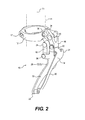
- the front derailleur 10 includes a mount 12.
- the seat tube 11 has a longitudinal central axis T1.
- the seat tube 11 may have any cross-sectional shape.
- the mount 12 is rigidly attached to the frame 13 of the bicycle 1, which will be considered in this application as a stationary reference point for the remaining components.
- a movable element in this embodiment a cage 14, is movably positioned relative to the mount 12 by an outer link 16 and an inner link 18.
- the outer link 16 has a first end pivotally connected to the mount 12 by a pivot pin 20 or other hinge.
- the other end of the outer link 16 is pivotally attached to the cage 14 by a pivot pin 22 or other hinge.
- the inner link 18 is pivotally attached to the mount 12 by a pivot pin 24 or other hinge.
- the lower end of the inner link 18 is attached to the cage 14 by a pivot pin 26 or other hinge.
- a spring 29 can also connect the cage 14 to the mount 12 or frame 1, in some embodiments, to bias the cage 14 as is described in more detail below.
- the cage 14 forms a structure that at least partially receives or straddles a portion the chain 5 with the chain 5 contained in between an outer side plate 30 of the cage 14 and an inner side plate 32 of the cage 14.
- the cage 14 also has a front end 31 and a rear region 33.
- the side plates 30 and 32 form contact portions that contact an exterior side of the chain 5 to displace the chain 5 laterally from one chainring to another in outboard and inboard directions.
- the cage 14 is moved laterally by providing an actuation force onto one of the links 16 or 18, or by providing an actuation force to the cage 14.
- the actuation force is applied to the outer link 16.
- the outer link 16 has an extension arm 34 which receives a cable bolt 36 to clamp onto or otherwise attached to the end of an actuation cable.
- the cable may be manipulated to drive the outer link 16 so that it pivots about the pivot pin 20 thus forcing the cage 14 laterally outward away from the seat tube 11.
- the return spring 29 is schematically depicted and biases the cage 14 in one direction, while the cable pulls in the opposite direction against the return spring bias force to control movement of the cage 14.
- the front derailleur 10 can be actuated by other force-providing devices, such as for example pneumatics, hydraulics, electric motors or electrically or otherwise generated elecric fields, or modulated versions of such, with or without a spring providing an opposed force.
- Other biasing devices may also be used in place of a spring.
- the outer link 16 is mounted such that the pivot pin 20 is oriented along a first or upper pivot axis A1.
- the lower pivot pin 22 is oriented along a second or lower pivot axis A2. Therefore, motion of the outer link 16 relative to the mount 12 is about axis A1, and motion of the cage 14 relative to the outer link 16 is about axis A2.
- Axes A1 and A2 are not parallel with each other, but rather deviate from each other angularly by a skew or nonzero angle A3.
- the non-zero angle A3 may be generally within the range of two to twenty degrees.
- FIG. 3 depicts the axis A1 being substantially perpendicular to the seat tube axis T1.
- FIG. 4 provides an outboard side view of the outer link 16 as viewed from the frame depicting the axis A1 and A2, as well as the skew angle A3.
- FIG. 5 is a rear view of the outer link 16 along the upper axis A1, and illustrating that the lower axis A2 is at an angle thereto.
- the inner link 18 is mounted such that the pivot pin 24 is oriented along a third pivot axis and the pivot pin 26 is oriented along a fourth pivot axis.
- the third and fourth pivot axes may not be parallel with each other, but rather deviate from each other angularly by a non-zero angle generally within the range of two to twenty degrees.
- FIGS. 7 and 8 depict the cage 14 of the front derailleur 10 in first and second positions respectively.
- the first position as shown in FIG. 7 may correspond to a cage position oriented more outwardly or outboard, away from the mount 12 on the seat tube 11, which may be the case for example after positioning the chain 5 on a chainring which is farther from the seat tube 11, in which in some examples may be a larger chainring.
- FIG. 8 illustrates the front derailleur cage 14 after it has been moved to a second position.
- the second position is a more inwardly or inboard position, moved relatively closer to the seat tube 11, which may be the case for example after positioning the chain on a chainring which is closer to the seat tube 11, in which in some examples may be a smaller chainring. Due to the skew angle, the sides 30 and 32 of the cage 24 are oriented at an angle relative to the line B1.
- the reference line B1 lies in a plane perpendicular to the front chainring axis 9.
- the sides 30 and 32 are generally as parallel to each other in this example, but may be angled relative to each other.
- the outboard or outer front chainring may be generally aligned with a center of the rear gearset, while the inboard or inner front chainring may be more inboard than a center of the rear cog set.
- the first position of FIG. 7 would generally correspond with an alignment of the chainring, while in the second case the cage 14 can be described as being canted outwardly so that its rear end 33 points rearwardly outwardly towards the center of the rear cog set.
- the cage 14 has rotated about a yaw axis Y1, relative to the first position shown in FIG. 7 . This is also shown by the difference between distance W1 compared to X1 and distance W2 relative to X2.
- the yaw axis Y1 is parallel to the seat tube axis T1.
- FIGS. 9 and 10 illustrate a second embodiment of the invention.
- a derailleur assembly 110 includes a mount 112 that can be affixed to the seat tube 11 generally as described above with respect to the mount 12 and a clasping bolt 117.
- a cage 114 is provided which is generally similar to the cage 14 described above, and includes side plates 130 and 132, rear end 133 and a cable guide 129.
- the embodiment of FIGS. 9 and 10 may also include a return spring or other biasing arrangement which is not shown in these views.
- a front link 116 is provided along with a rear link 118.
- the front link 116 is connected to the mount 112 by a pivot pin or other hinge 120 and is connected to the cage 114 by a pivot pin 122 or other hinge.
- the rear link 118 is connected to the mount 112 by a pivot pin 124 or other hinge and is connected to the cage 114 by a pivot pin 126 or other hinge.
- a distance L1 is defined between the pivot pins 120 and 124.
- a distance L2 is defined between pivot pins 122 and 126.
- the pivot pins 120 and 124 are oriented generally vertical, or generally parallel with the seat tube axis T1. In this embodiment, L1 and L2 are selected to be different lengths.
- lengths L3 and L4 are selected to be different lengths. Further in this embodiment L1 is selected to be longer than L2.
- the front link 116 may include an extension arm 134 to which is mountable a cable bolt, as described above with respect to extension arm 34.
- FIGS. 9 and 10 show that the cage 114 is disposed and oriented in a first position of FIG. 9 , which may be an outboard position, compared to a second position of FIG. 10 , which may be an inboard position. Specifically, with respect to a reference line
- first and second positions can be selected by selecting the difference in lengths between L1 and L2 so that the position in FIG. 9 generally corresponds to an average chain path when the chain is engaged on the outer ring, and the orientation of the cage in FIG. 10 generally corresponds to an average chain path when the chain is engaged on the inner ring.
- the reference line R1 lies in a plane perpendicular to the front chainring axis 9.
- FIG. 11 is a perspective view of a third embodiment.
- a derailleur 210 includes a mount 212 which can be substantially similar to that described with respect with mount 12 above.
- a cage 214 is also provided as described with respect to cage 14 above, including sides 230 and 232, front region 231, rear region 233 and return spring 229.
- an single link 216 is provided along with pivot pins 220 and 222 or other hinges, such that the single link 216 is connected to the mount 212 by the pivot pin 220 and to the cage 214 by the pivot pin 122.
- An extension arm 234 and cable bolt 236 are shown which may operate similar to the actuation extension 34 and cable bolt 36 described above.
- the extension arm or other derailleur parts can be operated by other than cable actuation such as by other force-providing devices, such as for example pneumatics, hydraulics, electric motors or electrically or otherwise generated electric fields, or modulated versions of such, with or without a spring providing opposed force. Also other biasing devices may be used in place of a spring.
- force-providing devices such as for example pneumatics, hydraulics, electric motors or electrically or otherwise generated electric fields, or modulated versions of such, with or without a spring providing opposed force.
- biasing devices may be used in place of a spring.
- This embodiment is an example where a single link 216 is used, such that movement of the cage is defined by the pivot pin 222, and also by contact between a cam surface 260 provided on the cage 214 and an opposing cam surface 262 provided on the mount.
- the surfaces 260 and 262 are illustrated as curved opposed surfaces, each convex and facing the other one, such that the cam surface 260 rides on and follows the cam surface 262.
- any other type of profiled, contacting, following or engaging surfaces may be used, such as for example a roller mounted on cage 214 configured to roll along cam surface 262.
- the axis of the pivot pin 220 is at an angle to the axis of the pivot pin 222 in the manner discussed above with respect to skew angle A3 between axis A1 and A2, and yaw axis Y1. Therefore, this embodiment will provide an angular motion about a reference yaw axis similar to that shown in FIGS. 7 and 8 .
- FIGS. 14 and 15 provide some additional details regarding some embodiments, with FIG. 14 showing a cage 314 in outboard first position and FIG. 15 showing the cage 314 in an inboard second position.
- the outer wall of the cage 330 and the inner wall of the cage 332 are not depicted as parallel to each other but are themselves at an angle ⁇ to each other. This angle ⁇ diverges to the rear such that the portions of the wall 330 and 332 that may contact the chain during shifting are spaced closer together towards the front of the cage and further apart towards the rear of the cage, as shown by the angle ⁇ between lines C1 and C3.
- FIGS. 14 and 15 also depict a cage that rotates about a yaw axis relative to a frame member such as a seat tube.
- the yaw axis is not separately labeled in this drawing but is represented by the center of the curved arrows indicating directions of rotation.
- the yaw angle of rotation between two positions can be selected to approximately or exactly correspond to the angle between the side walls 330 and 332. In such an example, the geometry can be selected so that in the position shown in FIG.
- the chain contacting surface outer wall 330 is aligned along line C3 parallel to the front chainring shown as line C2, and in the position shown in FIG. 15 the inner wall 332 is aligned along line C1 parallel to the direction of the front chainring shown as line C2.
- the front derailleur may be used with front drives having more than two chainrings, including three or more chainrings.
- the front derailleur geometry can be selected so that the overall change in yaw orientation of the cage is increased.
- the geometry can be selected to provide a suitably wide range of angular diversion of the longitudinal axis of the cage, or rotation about the yaw axis, to accommodate the range of chain angles.
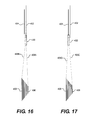
- FIGS. 16 and 17 are diagrams representing a front derailleur cage 430 along with a front drive having a large outward chainring 402 and a small inward chainring 404, and a rear cog set having multiple cogs disposed between a small outward cog 406 and a large inward cog 408.
- the possible angles of the chain 80 are shown in dotted lines 409A, 409 B, 409C and 409D, such that it can be seen at the cage 430 changes angle with its rear end pointing somewhat inboard in FIG. 16 compared to FIG. 17 in order to accommodate the possible range of chain angles.
- the accommodation of the range of chain angles in some instances can reduce or eliminate rasping after gear changes.
- Some embodiments also provide a method of shifting gears, for example bicycle gears.
- the method can include moving a movable element, such as a chain cage 14, from a first position to a second position, where the movement causes the cage 14 to contact an exterior side of a chain to displace the chain, and the movement includes a lateral displacement relative to the frame combined with rotation of the cage about a yaw axis.
- Some embodiments are implemented with the cage being moved in a lateral side-to-side direction that is generally perpendicular to the path of the chain, and with the yaw axis being generally perpendicular to the direction of lateral motion of the cage.
- the drawings illustrate a cage that has at least two side plates that are connected as a unit and both move laterally and about the yaw axis together.
- embodiments are possible using the structures described herein to move only one or the other side plate independently of the other such that only one of them has rotation about the yaw axis.
- the cage may be described as moving laterally, or side-to-side with respect to the frame. However, this movement so described does not necessarily need to be linear, and in fact can include a curved or arcuate path that appears lateral when viewed from a given perspective.
- the embodiments described here may be suitable for use with index shift systems in which the derailleur moves between preset lateral positions. Additionally, the embodiments described may be suitable for use with trim-adjusting derailleurs in which the derailleur adjusts the cage lateral position after shifting has occurred to reduce or eliminate rasping. Further, various embodiments described here do not depend on a chain riding on tooth sprockets or cogs, but rather can be used with any elongated band expanding from front to back that is being moved laterally at the derailleur location. Other band engagement systems might include tooth belts or v-belts being moved between tooth wheels or pulleys.
- references in this description to a vertical direction, front ends, rear ends, and sides is merely for setting reference orientations and it will be appreciated that some embodiments of the device may be oriented in any spatial arrangement and affixed to a component in any spatial arrangement.
- the reference to yaw refers to a rotational movement compared to a lateral displacement but does not need to be about a vertical axis.
- the embodiments described above include examples where the cage is depicted as generally extending or projecting "below" the mount and link components; however, the cage may extend upward or laterally or in any spatial direction relative to such other components.
Landscapes
- Engineering & Computer Science (AREA)
- Chemical & Material Sciences (AREA)
- Combustion & Propulsion (AREA)
- Transportation (AREA)
- Mechanical Engineering (AREA)
- Devices For Conveying Motion By Means Of Endless Flexible Members (AREA)
- Transmissions By Endless Flexible Members (AREA)
Applications Claiming Priority (1)
| Application Number | Priority Date | Filing Date | Title |
|---|---|---|---|
| US12/968,533 US8678962B2 (en) | 2010-12-15 | 2010-12-15 | Bicycle derailleur and method |
Publications (2)
| Publication Number | Publication Date |
|---|---|
| EP2465762A1 true EP2465762A1 (fr) | 2012-06-20 |
| EP2465762B1 EP2465762B1 (fr) | 2017-01-25 |
Family
ID=45440032
Family Applications (2)
| Application Number | Title | Priority Date | Filing Date |
|---|---|---|---|
| EP11009869.6A Active EP2465762B1 (fr) | 2010-12-15 | 2011-12-15 | Dérailleur de bicyclette et procédé |
| EP11009868.8A Active EP2465761B1 (fr) | 2010-12-15 | 2011-12-15 | Dérailleur de bicyclette et procédé |
Family Applications After (1)
| Application Number | Title | Priority Date | Filing Date |
|---|---|---|---|
| EP11009868.8A Active EP2465761B1 (fr) | 2010-12-15 | 2011-12-15 | Dérailleur de bicyclette et procédé |
Country Status (4)
| Country | Link |
|---|---|
| US (2) | US8678962B2 (fr) |
| EP (2) | EP2465762B1 (fr) |
| CN (1) | CN102530180B (fr) |
| TW (1) | TWI498251B (fr) |
Families Citing this family (25)
| Publication number | Priority date | Publication date | Assignee | Title |
|---|---|---|---|---|
| US7722072B2 (en) | 2004-09-15 | 2010-05-25 | Yeti Cycling, Llc | Rear suspension system for a bicycle |
| EP2605953B1 (fr) | 2010-08-20 | 2021-06-16 | Yeti Cycling LLC | Système de suspension à liaisons |
| US9821879B2 (en) | 2010-08-20 | 2017-11-21 | Yeti Cycling, Llc | Reciprocating rail movement suspension system |
| US8678963B2 (en) * | 2011-09-21 | 2014-03-25 | Shimano Inc. | Bicycle front derailleur |
| US10766563B2 (en) | 2013-01-16 | 2020-09-08 | Yeti Cyclying, Llc | Rail suspension with integral shock and dampening mechanism |
| US9836076B2 (en) * | 2013-01-31 | 2017-12-05 | Shimano Inc. | Bicycle operating device |
| US20140265220A1 (en) * | 2013-03-15 | 2014-09-18 | Zike, Llc | Low Profile Derailleur For Chain Driven Personal Vehicle |
| ES2673245T3 (es) | 2013-03-15 | 2018-06-20 | Wick Werks, LLC | Desviador delantero de pivote único y trinquete de cadena de dos lados |
| JP2015016791A (ja) * | 2013-07-11 | 2015-01-29 | 株式会社シマノ | フロントディレーラ |
| JP2015016792A (ja) * | 2013-07-11 | 2015-01-29 | 株式会社シマノ | フロントディレーラ |
| US9248885B2 (en) * | 2013-09-30 | 2016-02-02 | Shimano Inc. | Derailleur |
| DE202014001791U1 (de) * | 2014-02-27 | 2014-03-11 | Sram Deutschland Gmbh | Kettenumwerfer für ein Fahrrad |
| US9334018B2 (en) * | 2014-07-28 | 2016-05-10 | Shimano Inc. | Bicycle derailleur |
| WO2016094717A1 (fr) | 2014-12-10 | 2016-06-16 | Yeti Cycling, Llc | Mécanisme de dérailleur linéaire |
| US10252773B2 (en) * | 2016-04-05 | 2019-04-09 | Shimano Inc. | Bicycle front derailleur |
| TWI611124B (zh) * | 2017-02-24 | 2018-01-11 | 彥豪金屬工業股份有限公司 | 變速器總成及其換檔狀態之偵測方法 |
| US11173983B2 (en) | 2017-03-17 | 2021-11-16 | Yeti Cycling, Llc | Vehicle suspension linkage |
| IT201700035716A1 (it) * | 2017-03-31 | 2018-10-01 | Campagnolo Srl | Deragliatore posteriore di bicicletta |
| US10926830B2 (en) | 2017-07-07 | 2021-02-23 | Yeti Cycling, Llc | Vehicle suspension linkage |
| US12077241B2 (en) | 2019-02-01 | 2024-09-03 | Yeti Cycling, Llc | Multi-body vehicle suspension linkage |
| TWI752306B (zh) * | 2019-03-20 | 2022-01-11 | 彥豪金屬工業股份有限公司 | 自行車變速器 |
| US11697474B2 (en) * | 2020-06-30 | 2023-07-11 | Shimano Inc. | Bicycle derailleur and link pin for bicycle derailleur |
| US11745828B2 (en) * | 2020-06-30 | 2023-09-05 | Shimano Inc. | Front derailleur and chain guide of bicycle derailleur |
| US11565772B2 (en) * | 2020-06-30 | 2023-01-31 | Shimano Inc. | Bicycle derailleur, bicycle gear structure, bicycle motor unit, and front derailleur |
| US11787506B2 (en) * | 2021-03-30 | 2023-10-17 | Shimano Inc. | Derailleur for human-powered vehicle |
Citations (5)
| Publication number | Priority date | Publication date | Assignee | Title |
|---|---|---|---|---|
| JPS5757194U (fr) | 1980-09-24 | 1982-04-03 | ||
| US4362522A (en) * | 1978-12-04 | 1982-12-07 | Huret Roger H M | Derailleur for a chainwheel assembly for a bicycle |
| US4781657A (en) * | 1986-04-28 | 1988-11-01 | Shimano Industrial Company Limited | Front derailleur for a bicycle |
| FR2640931A1 (en) * | 1988-12-27 | 1990-06-29 | Sachs Ind Sa Huret Maillard Re | Dérailleur for a bicycle front crank gear |
| US4955849A (en) * | 1988-06-30 | 1990-09-11 | Shimano Industrial Co., Ltd. | Front derailleur for use in bicycle |
Family Cites Families (22)
| Publication number | Priority date | Publication date | Assignee | Title |
|---|---|---|---|---|
| JPS5383246A (en) * | 1976-12-28 | 1978-07-22 | Shimano Industrial Co | Derailer for bicycle |
| JPS53102550A (en) | 1977-02-21 | 1978-09-06 | Shimano Industrial Co | Front derailer |
| JPS5649832Y2 (fr) * | 1977-07-12 | 1981-11-20 | ||
| JPS609120Y2 (ja) * | 1979-08-15 | 1985-04-01 | 株式会社シマノ | 自転車用フロントデイレ−ラ− |
| US4424048A (en) | 1980-06-17 | 1984-01-03 | Shimano Industrial Company Limited | Front derailleur for a bicycle having horizontally positioned linkage members |
| JPS5757194A (en) | 1980-09-16 | 1982-04-06 | Komatsu Mfg Co Ltd | Safety device for crane with jib |
| FR2532906B1 (fr) * | 1982-09-15 | 1988-01-15 | Huret & Fils | Derailleur de pedalier perfectionne pour bicyclette |
| FR2534216A1 (fr) | 1982-10-12 | 1984-04-13 | Huret & Fils | Derailleur pour cycle a dispositif de guidage de chaine orientable |
| JPS6030892U (ja) * | 1983-08-08 | 1985-03-02 | 株式会社シマノ | 自転車用変速操作装置 |
| JPS61161001A (ja) * | 1985-01-09 | 1986-07-21 | Nec Corp | 可変減衰器 |
| US5197927B1 (en) * | 1991-03-20 | 2000-10-17 | Sram Corp | Bicycle derailleur cable actuating system |
| FR2788485B1 (fr) * | 1999-01-19 | 2001-02-23 | Frederic Vaillant | Dispositif de changement de vitesse pour cycle |
| US6726587B2 (en) * | 2001-10-19 | 2004-04-27 | Shimano, Inc. | Adjustable bicycle derailleur |
| US7014584B2 (en) * | 2002-12-27 | 2006-03-21 | Shimano Inc. | Top pull type front derailleur |
| US7081058B2 (en) * | 2003-02-12 | 2006-07-25 | Shimano Inc. | Bicycle front derailleur |
| DE602005026074D1 (de) * | 2004-07-08 | 2011-03-03 | Yamaha Motor Co Ltd | Antrieb und Grätschsitz-Fahrzeug, das mit dem Antrieb versehen ist |
| US7438658B2 (en) | 2004-08-30 | 2008-10-21 | Shimano Inc. | Bicycle front derailleur |
| JP4682579B2 (ja) * | 2004-10-05 | 2011-05-11 | スズキ株式会社 | 自動二輪車のパワーユニット |
| JP2006224875A (ja) | 2005-02-18 | 2006-08-31 | Shimano Inc | 自転車用変速制御装置 |
| US7677998B2 (en) | 2006-01-31 | 2010-03-16 | Shimano Inc. | Bicycle front derailleur |
| US7914407B2 (en) * | 2007-05-29 | 2011-03-29 | Shimano Inc. | Bicycle front derailleur assembly |
| US9284017B2 (en) * | 2010-12-15 | 2016-03-15 | Sram, Llc | Bicycle derailleur and method |
-
2010
- 2010-12-15 US US12/968,533 patent/US8678962B2/en active Active
-
2011
- 2011-11-30 TW TW100143954A patent/TWI498251B/zh active
- 2011-12-15 CN CN201110421521.0A patent/CN102530180B/zh active Active
- 2011-12-15 EP EP11009869.6A patent/EP2465762B1/fr active Active
- 2011-12-15 EP EP11009868.8A patent/EP2465761B1/fr active Active
-
2014
- 2014-02-21 US US14/186,121 patent/US9493212B2/en active Active
Patent Citations (5)
| Publication number | Priority date | Publication date | Assignee | Title |
|---|---|---|---|---|
| US4362522A (en) * | 1978-12-04 | 1982-12-07 | Huret Roger H M | Derailleur for a chainwheel assembly for a bicycle |
| JPS5757194U (fr) | 1980-09-24 | 1982-04-03 | ||
| US4781657A (en) * | 1986-04-28 | 1988-11-01 | Shimano Industrial Company Limited | Front derailleur for a bicycle |
| US4955849A (en) * | 1988-06-30 | 1990-09-11 | Shimano Industrial Co., Ltd. | Front derailleur for use in bicycle |
| FR2640931A1 (en) * | 1988-12-27 | 1990-06-29 | Sachs Ind Sa Huret Maillard Re | Dérailleur for a bicycle front crank gear |
Non-Patent Citations (1)
| Title |
|---|
| "SHIMANO BICYCLE SYSTEM COMPONENTS", CATALOGUE, April 1982 (1982-04-01), pages 11 - 12, XP003032691 |
Also Published As
| Publication number | Publication date |
|---|---|
| US20140171242A1 (en) | 2014-06-19 |
| EP2465761B1 (fr) | 2016-05-04 |
| US9493212B2 (en) | 2016-11-15 |
| TW201223819A (en) | 2012-06-16 |
| CN102530180B (zh) | 2014-11-26 |
| US20120157250A1 (en) | 2012-06-21 |
| EP2465762B1 (fr) | 2017-01-25 |
| TWI498251B (zh) | 2015-09-01 |
| US8678962B2 (en) | 2014-03-25 |
| CN102530180A (zh) | 2012-07-04 |
| EP2465761A1 (fr) | 2012-06-20 |
Similar Documents
| Publication | Publication Date | Title |
|---|---|---|
| EP2465762B1 (fr) | Dérailleur de bicyclette et procédé | |
| US9127766B2 (en) | Bicycle derailleur | |
| US11161568B2 (en) | Rear derailleur | |
| JP6188394B2 (ja) | 自転車のスプロケットアセンブリ | |
| US9796450B2 (en) | Bicycle front derailleur | |
| TWI694034B (zh) | 自行車前變速器 | |
| CN108688771B (zh) | 自行车后变速器 | |
| TWI720079B (zh) | 鏈環 | |
| US9284017B2 (en) | Bicycle derailleur and method | |
| US20060122016A1 (en) | Bicycle derailleur | |
| US20150353166A1 (en) | Bicycle front derailleur | |
| TW202030429A (zh) | 腳踏車鏈環、腳踏車曲柄齒盤及腳踏車傳動系統 | |
| US11541963B2 (en) | Adjustment mechanism and drive | |
| US10131404B2 (en) | Bicycle front derailleur | |
| US7806792B2 (en) | Auxiliary bicycle shifting component | |
| CN102741584A (zh) | 无声链 | |
| US20040005951A1 (en) | Front derailleur for a bicycle | |
| TWI532634B (zh) | 自行車變速器及方法 | |
| KR200468085Y1 (ko) | 무단변속형 체인 전동장치 | |
| EP2679480B1 (fr) | Véhicule | |
| EP4127510A1 (fr) | Chaîne dentée pour bicyclette | |
| KR101156106B1 (ko) | 자전거용 변속장치 및 이를 구비하는 자전거 | |
| TW202319665A (zh) | 浮動式從動機構 | |
| CN117836200A (zh) | 链条张紧器 |
Legal Events
| Date | Code | Title | Description |
|---|---|---|---|
| PUAI | Public reference made under article 153(3) epc to a published international application that has entered the european phase |
Free format text: ORIGINAL CODE: 0009012 |
|
| AK | Designated contracting states |
Kind code of ref document: A1 Designated state(s): AL AT BE BG CH CY CZ DE DK EE ES FI FR GB GR HR HU IE IS IT LI LT LU LV MC MK MT NL NO PL PT RO RS SE SI SK SM TR |
|
| AX | Request for extension of the european patent |
Extension state: BA ME |
|
| 17P | Request for examination filed |
Effective date: 20120606 |
|
| TPAC | Observations filed by third parties |
Free format text: ORIGINAL CODE: EPIDOSNTIPA |
|
| TPAC | Observations filed by third parties |
Free format text: ORIGINAL CODE: EPIDOSNTIPA |
|
| 17Q | First examination report despatched |
Effective date: 20151103 |
|
| GRAP | Despatch of communication of intention to grant a patent |
Free format text: ORIGINAL CODE: EPIDOSNIGR1 |
|
| INTG | Intention to grant announced |
Effective date: 20160712 |
|
| STAA | Information on the status of an ep patent application or granted ep patent |
Free format text: STATUS: GRANT OF PATENT IS INTENDED |
|
| GRAS | Grant fee paid |
Free format text: ORIGINAL CODE: EPIDOSNIGR3 |
|
| RAP1 | Party data changed (applicant data changed or rights of an application transferred) |
Owner name: SRAM, LLC. |
|
| GRAA | (expected) grant |
Free format text: ORIGINAL CODE: 0009210 |
|
| STAA | Information on the status of an ep patent application or granted ep patent |
Free format text: STATUS: THE PATENT HAS BEEN GRANTED |
|
| AK | Designated contracting states |
Kind code of ref document: B1 Designated state(s): AL AT BE BG CH CY CZ DE DK EE ES FI FR GB GR HR HU IE IS IT LI LT LU LV MC MK MT NL NO PL PT RO RS SE SI SK SM TR |
|
| REG | Reference to a national code |
Ref country code: GB Ref legal event code: FG4D |
|
| REG | Reference to a national code |
Ref country code: CH Ref legal event code: EP |
|
| REG | Reference to a national code |
Ref country code: AT Ref legal event code: REF Ref document number: 863932 Country of ref document: AT Kind code of ref document: T Effective date: 20170215 |
|
| REG | Reference to a national code |
Ref country code: IE Ref legal event code: FG4D Ref country code: NL Ref legal event code: FP |
|
| REG | Reference to a national code |
Ref country code: DE Ref legal event code: R096 Ref document number: 602011034587 Country of ref document: DE |
|
| REG | Reference to a national code |
Ref country code: LT Ref legal event code: MG4D |
|
| REG | Reference to a national code |
Ref country code: AT Ref legal event code: MK05 Ref document number: 863932 Country of ref document: AT Kind code of ref document: T Effective date: 20170125 |
|
| PG25 | Lapsed in a contracting state [announced via postgrant information from national office to epo] |
Ref country code: HR Free format text: LAPSE BECAUSE OF FAILURE TO SUBMIT A TRANSLATION OF THE DESCRIPTION OR TO PAY THE FEE WITHIN THE PRESCRIBED TIME-LIMIT Effective date: 20170125 Ref country code: IS Free format text: LAPSE BECAUSE OF FAILURE TO SUBMIT A TRANSLATION OF THE DESCRIPTION OR TO PAY THE FEE WITHIN THE PRESCRIBED TIME-LIMIT Effective date: 20170525 Ref country code: NO Free format text: LAPSE BECAUSE OF FAILURE TO SUBMIT A TRANSLATION OF THE DESCRIPTION OR TO PAY THE FEE WITHIN THE PRESCRIBED TIME-LIMIT Effective date: 20170425 Ref country code: FI Free format text: LAPSE BECAUSE OF FAILURE TO SUBMIT A TRANSLATION OF THE DESCRIPTION OR TO PAY THE FEE WITHIN THE PRESCRIBED TIME-LIMIT Effective date: 20170125 Ref country code: GR Free format text: LAPSE BECAUSE OF FAILURE TO SUBMIT A TRANSLATION OF THE DESCRIPTION OR TO PAY THE FEE WITHIN THE PRESCRIBED TIME-LIMIT Effective date: 20170426 Ref country code: LT Free format text: LAPSE BECAUSE OF FAILURE TO SUBMIT A TRANSLATION OF THE DESCRIPTION OR TO PAY THE FEE WITHIN THE PRESCRIBED TIME-LIMIT Effective date: 20170125 |
|
| PG25 | Lapsed in a contracting state [announced via postgrant information from national office to epo] |
Ref country code: AT Free format text: LAPSE BECAUSE OF FAILURE TO SUBMIT A TRANSLATION OF THE DESCRIPTION OR TO PAY THE FEE WITHIN THE PRESCRIBED TIME-LIMIT Effective date: 20170125 Ref country code: PT Free format text: LAPSE BECAUSE OF FAILURE TO SUBMIT A TRANSLATION OF THE DESCRIPTION OR TO PAY THE FEE WITHIN THE PRESCRIBED TIME-LIMIT Effective date: 20170525 Ref country code: ES Free format text: LAPSE BECAUSE OF FAILURE TO SUBMIT A TRANSLATION OF THE DESCRIPTION OR TO PAY THE FEE WITHIN THE PRESCRIBED TIME-LIMIT Effective date: 20170125 Ref country code: SE Free format text: LAPSE BECAUSE OF FAILURE TO SUBMIT A TRANSLATION OF THE DESCRIPTION OR TO PAY THE FEE WITHIN THE PRESCRIBED TIME-LIMIT Effective date: 20170125 Ref country code: BG Free format text: LAPSE BECAUSE OF FAILURE TO SUBMIT A TRANSLATION OF THE DESCRIPTION OR TO PAY THE FEE WITHIN THE PRESCRIBED TIME-LIMIT Effective date: 20170425 Ref country code: RS Free format text: LAPSE BECAUSE OF FAILURE TO SUBMIT A TRANSLATION OF THE DESCRIPTION OR TO PAY THE FEE WITHIN THE PRESCRIBED TIME-LIMIT Effective date: 20170125 Ref country code: PL Free format text: LAPSE BECAUSE OF FAILURE TO SUBMIT A TRANSLATION OF THE DESCRIPTION OR TO PAY THE FEE WITHIN THE PRESCRIBED TIME-LIMIT Effective date: 20170125 Ref country code: LV Free format text: LAPSE BECAUSE OF FAILURE TO SUBMIT A TRANSLATION OF THE DESCRIPTION OR TO PAY THE FEE WITHIN THE PRESCRIBED TIME-LIMIT Effective date: 20170125 |
|
| REG | Reference to a national code |
Ref country code: DE Ref legal event code: R097 Ref document number: 602011034587 Country of ref document: DE |
|
| PG25 | Lapsed in a contracting state [announced via postgrant information from national office to epo] |
Ref country code: CZ Free format text: LAPSE BECAUSE OF FAILURE TO SUBMIT A TRANSLATION OF THE DESCRIPTION OR TO PAY THE FEE WITHIN THE PRESCRIBED TIME-LIMIT Effective date: 20170125 Ref country code: RO Free format text: LAPSE BECAUSE OF FAILURE TO SUBMIT A TRANSLATION OF THE DESCRIPTION OR TO PAY THE FEE WITHIN THE PRESCRIBED TIME-LIMIT Effective date: 20170125 Ref country code: SK Free format text: LAPSE BECAUSE OF FAILURE TO SUBMIT A TRANSLATION OF THE DESCRIPTION OR TO PAY THE FEE WITHIN THE PRESCRIBED TIME-LIMIT Effective date: 20170125 Ref country code: IT Free format text: LAPSE BECAUSE OF FAILURE TO SUBMIT A TRANSLATION OF THE DESCRIPTION OR TO PAY THE FEE WITHIN THE PRESCRIBED TIME-LIMIT Effective date: 20170125 Ref country code: EE Free format text: LAPSE BECAUSE OF FAILURE TO SUBMIT A TRANSLATION OF THE DESCRIPTION OR TO PAY THE FEE WITHIN THE PRESCRIBED TIME-LIMIT Effective date: 20170125 |
|
| REG | Reference to a national code |
Ref country code: FR Ref legal event code: PLFP Year of fee payment: 7 |
|
| PG25 | Lapsed in a contracting state [announced via postgrant information from national office to epo] |
Ref country code: DK Free format text: LAPSE BECAUSE OF FAILURE TO SUBMIT A TRANSLATION OF THE DESCRIPTION OR TO PAY THE FEE WITHIN THE PRESCRIBED TIME-LIMIT Effective date: 20170125 Ref country code: SM Free format text: LAPSE BECAUSE OF FAILURE TO SUBMIT A TRANSLATION OF THE DESCRIPTION OR TO PAY THE FEE WITHIN THE PRESCRIBED TIME-LIMIT Effective date: 20170125 |
|
| PLBE | No opposition filed within time limit |
Free format text: ORIGINAL CODE: 0009261 |
|
| STAA | Information on the status of an ep patent application or granted ep patent |
Free format text: STATUS: NO OPPOSITION FILED WITHIN TIME LIMIT |
|
| 26N | No opposition filed |
Effective date: 20171026 |
|
| PG25 | Lapsed in a contracting state [announced via postgrant information from national office to epo] |
Ref country code: SI Free format text: LAPSE BECAUSE OF FAILURE TO SUBMIT A TRANSLATION OF THE DESCRIPTION OR TO PAY THE FEE WITHIN THE PRESCRIBED TIME-LIMIT Effective date: 20170125 |
|
| REG | Reference to a national code |
Ref country code: CH Ref legal event code: PL |
|
| GBPC | Gb: european patent ceased through non-payment of renewal fee |
Effective date: 20171215 |
|
| REG | Reference to a national code |
Ref country code: IE Ref legal event code: MM4A |
|
| PG25 | Lapsed in a contracting state [announced via postgrant information from national office to epo] |
Ref country code: MT Free format text: LAPSE BECAUSE OF NON-PAYMENT OF DUE FEES Effective date: 20171215 Ref country code: LU Free format text: LAPSE BECAUSE OF NON-PAYMENT OF DUE FEES Effective date: 20171215 |
|
| REG | Reference to a national code |
Ref country code: BE Ref legal event code: MM Effective date: 20171231 |
|
| PG25 | Lapsed in a contracting state [announced via postgrant information from national office to epo] |
Ref country code: IE Free format text: LAPSE BECAUSE OF NON-PAYMENT OF DUE FEES Effective date: 20171215 |
|
| PG25 | Lapsed in a contracting state [announced via postgrant information from national office to epo] |
Ref country code: LI Free format text: LAPSE BECAUSE OF NON-PAYMENT OF DUE FEES Effective date: 20171231 Ref country code: CH Free format text: LAPSE BECAUSE OF NON-PAYMENT OF DUE FEES Effective date: 20171231 Ref country code: BE Free format text: LAPSE BECAUSE OF NON-PAYMENT OF DUE FEES Effective date: 20171231 Ref country code: GB Free format text: LAPSE BECAUSE OF NON-PAYMENT OF DUE FEES Effective date: 20171215 |
|
| PGFP | Annual fee paid to national office [announced via postgrant information from national office to epo] |
Ref country code: NL Payment date: 20181203 Year of fee payment: 8 |
|
| PGFP | Annual fee paid to national office [announced via postgrant information from national office to epo] |
Ref country code: FR Payment date: 20181120 Year of fee payment: 8 |
|
| PG25 | Lapsed in a contracting state [announced via postgrant information from national office to epo] |
Ref country code: HU Free format text: LAPSE BECAUSE OF FAILURE TO SUBMIT A TRANSLATION OF THE DESCRIPTION OR TO PAY THE FEE WITHIN THE PRESCRIBED TIME-LIMIT; INVALID AB INITIO Effective date: 20111215 Ref country code: MC Free format text: LAPSE BECAUSE OF FAILURE TO SUBMIT A TRANSLATION OF THE DESCRIPTION OR TO PAY THE FEE WITHIN THE PRESCRIBED TIME-LIMIT Effective date: 20170125 |
|
| PG25 | Lapsed in a contracting state [announced via postgrant information from national office to epo] |
Ref country code: CY Free format text: LAPSE BECAUSE OF NON-PAYMENT OF DUE FEES Effective date: 20170125 |
|
| PG25 | Lapsed in a contracting state [announced via postgrant information from national office to epo] |
Ref country code: MK Free format text: LAPSE BECAUSE OF FAILURE TO SUBMIT A TRANSLATION OF THE DESCRIPTION OR TO PAY THE FEE WITHIN THE PRESCRIBED TIME-LIMIT Effective date: 20170125 |
|
| PG25 | Lapsed in a contracting state [announced via postgrant information from national office to epo] |
Ref country code: TR Free format text: LAPSE BECAUSE OF FAILURE TO SUBMIT A TRANSLATION OF THE DESCRIPTION OR TO PAY THE FEE WITHIN THE PRESCRIBED TIME-LIMIT Effective date: 20170125 |
|
| PG25 | Lapsed in a contracting state [announced via postgrant information from national office to epo] |
Ref country code: AL Free format text: LAPSE BECAUSE OF FAILURE TO SUBMIT A TRANSLATION OF THE DESCRIPTION OR TO PAY THE FEE WITHIN THE PRESCRIBED TIME-LIMIT Effective date: 20170125 |
|
| REG | Reference to a national code |
Ref country code: NL Ref legal event code: MM Effective date: 20200101 |
|
| PG25 | Lapsed in a contracting state [announced via postgrant information from national office to epo] |
Ref country code: NL Free format text: LAPSE BECAUSE OF NON-PAYMENT OF DUE FEES Effective date: 20200101 |
|
| PG25 | Lapsed in a contracting state [announced via postgrant information from national office to epo] |
Ref country code: FR Free format text: LAPSE BECAUSE OF NON-PAYMENT OF DUE FEES Effective date: 20191231 |
|
| REG | Reference to a national code |
Ref country code: DE Ref legal event code: R082 Ref document number: 602011034587 Country of ref document: DE Representative=s name: THUM, MOETSCH, WEICKERT PATENTANWAELTE PARTG M, DE Ref country code: DE Ref legal event code: R082 Ref document number: 602011034587 Country of ref document: DE Representative=s name: THUM & PARTNER THUM MOETSCH WEICKERT PATENTANW, DE |
|
| P01 | Opt-out of the competence of the unified patent court (upc) registered |
Effective date: 20230524 |
|
| PGFP | Annual fee paid to national office [announced via postgrant information from national office to epo] |
Ref country code: DE Payment date: 20231108 Year of fee payment: 13 |