EP2464537B2 - Kontinuierlich angetriebenes neigungsfreispielsystem und feingestanzte getriebenabe dafür - Google Patents
Kontinuierlich angetriebenes neigungsfreispielsystem und feingestanzte getriebenabe dafür Download PDFInfo
- Publication number
- EP2464537B2 EP2464537B2 EP10808752.9A EP10808752A EP2464537B2 EP 2464537 B2 EP2464537 B2 EP 2464537B2 EP 10808752 A EP10808752 A EP 10808752A EP 2464537 B2 EP2464537 B2 EP 2464537B2
- Authority
- EP
- European Patent Office
- Prior art keywords
- carrier
- hub
- circumferential surface
- gear
- tab
- Prior art date
- Legal status (The legal status is an assumption and is not a legal conclusion. Google has not performed a legal analysis and makes no representation as to the accuracy of the status listed.)
- Active
Links
Images








Classifications
-
- B—PERFORMING OPERATIONS; TRANSPORTING
- B60—VEHICLES IN GENERAL
- B60N—SEATS SPECIALLY ADAPTED FOR VEHICLES; VEHICLE PASSENGER ACCOMMODATION NOT OTHERWISE PROVIDED FOR
- B60N2/00—Seats specially adapted for vehicles; Arrangement or mounting of seats in vehicles
- B60N2/02—Seats specially adapted for vehicles; Arrangement or mounting of seats in vehicles the seat or part thereof being movable, e.g. adjustable
- B60N2/22—Seats specially adapted for vehicles; Arrangement or mounting of seats in vehicles the seat or part thereof being movable, e.g. adjustable the back-rest being adjustable
- B60N2/225—Seats specially adapted for vehicles; Arrangement or mounting of seats in vehicles the seat or part thereof being movable, e.g. adjustable the back-rest being adjustable by cycloidal or planetary mechanisms
- B60N2/2252—Seats specially adapted for vehicles; Arrangement or mounting of seats in vehicles the seat or part thereof being movable, e.g. adjustable the back-rest being adjustable by cycloidal or planetary mechanisms in which the central axis of the gearing lies inside the periphery of an orbital gear, e.g. one gear without sun gear
-
- B—PERFORMING OPERATIONS; TRANSPORTING
- B21—MECHANICAL METAL-WORKING WITHOUT ESSENTIALLY REMOVING MATERIAL; PUNCHING METAL
- B21D—WORKING OR PROCESSING OF SHEET METAL OR METAL TUBES, RODS OR PROFILES WITHOUT ESSENTIALLY REMOVING MATERIAL; PUNCHING METAL
- B21D53/00—Making other particular articles
- B21D53/26—Making other particular articles wheels or the like
- B21D53/28—Making other particular articles wheels or the like gear wheels
-
- B—PERFORMING OPERATIONS; TRANSPORTING
- B60—VEHICLES IN GENERAL
- B60N—SEATS SPECIALLY ADAPTED FOR VEHICLES; VEHICLE PASSENGER ACCOMMODATION NOT OTHERWISE PROVIDED FOR
- B60N2/00—Seats specially adapted for vehicles; Arrangement or mounting of seats in vehicles
- B60N2/02—Seats specially adapted for vehicles; Arrangement or mounting of seats in vehicles the seat or part thereof being movable, e.g. adjustable
- B60N2/20—Seats specially adapted for vehicles; Arrangement or mounting of seats in vehicles the seat or part thereof being movable, e.g. adjustable the back-rest being tiltable, e.g. to permit easy access
-
- B—PERFORMING OPERATIONS; TRANSPORTING
- B60—VEHICLES IN GENERAL
- B60N—SEATS SPECIALLY ADAPTED FOR VEHICLES; VEHICLE PASSENGER ACCOMMODATION NOT OTHERWISE PROVIDED FOR
- B60N2/00—Seats specially adapted for vehicles; Arrangement or mounting of seats in vehicles
- B60N2/02—Seats specially adapted for vehicles; Arrangement or mounting of seats in vehicles the seat or part thereof being movable, e.g. adjustable
- B60N2/22—Seats specially adapted for vehicles; Arrangement or mounting of seats in vehicles the seat or part thereof being movable, e.g. adjustable the back-rest being adjustable
- B60N2/225—Seats specially adapted for vehicles; Arrangement or mounting of seats in vehicles the seat or part thereof being movable, e.g. adjustable the back-rest being adjustable by cycloidal or planetary mechanisms
- B60N2/2254—Seats specially adapted for vehicles; Arrangement or mounting of seats in vehicles the seat or part thereof being movable, e.g. adjustable the back-rest being adjustable by cycloidal or planetary mechanisms provided with braking systems
-
- Y—GENERAL TAGGING OF NEW TECHNOLOGICAL DEVELOPMENTS; GENERAL TAGGING OF CROSS-SECTIONAL TECHNOLOGIES SPANNING OVER SEVERAL SECTIONS OF THE IPC; TECHNICAL SUBJECTS COVERED BY FORMER USPC CROSS-REFERENCE ART COLLECTIONS [XRACs] AND DIGESTS
- Y10—TECHNICAL SUBJECTS COVERED BY FORMER USPC
- Y10T—TECHNICAL SUBJECTS COVERED BY FORMER US CLASSIFICATION
- Y10T29/00—Metal working
- Y10T29/49—Method of mechanical manufacture
- Y10T29/49462—Gear making
- Y10T29/49467—Gear shaping
- Y10T29/49472—Punching or stamping
-
- Y—GENERAL TAGGING OF NEW TECHNOLOGICAL DEVELOPMENTS; GENERAL TAGGING OF CROSS-SECTIONAL TECHNOLOGIES SPANNING OVER SEVERAL SECTIONS OF THE IPC; TECHNICAL SUBJECTS COVERED BY FORMER USPC CROSS-REFERENCE ART COLLECTIONS [XRACs] AND DIGESTS
- Y10—TECHNICAL SUBJECTS COVERED BY FORMER USPC
- Y10T—TECHNICAL SUBJECTS COVERED BY FORMER US CLASSIFICATION
- Y10T74/00—Machine element or mechanism
- Y10T74/19—Gearing
- Y10T74/1954—Eccentric driving shaft and axle
Definitions
- the present invention relates to an adjustment device for a vehicle seat and more particularly, to a tilt adjustment device which allows the seat back of a vehicle seat to move relative to the base of the vehicle seat.
- This tilt device is also referred to as a recline mechanism and generally includes an inner gear and outer gear which are moveable to relative one another in order to provide tilt adjustment of the seat back relative to the seat base.
- the inner gear is fitted within the outer gear and is at least one tooth smaller such that when a rotating adjustment element drives an eccentric ring or carrier about an axis causing wedge segments to be dragged and eccentrically wedged around the rotational axis, the outer gear moves radially about an axis.
- the outer gear is driven approximately ten degrees about the axis. After the seat back is in the preferred position, the inner and outer gears are locked from relative movement due to the wedge segments ensuring that the inner and outer gears stay meshed.
- DE 10 2004 013 272 B3 discloses a recline mechanism for a vehicle seat comprising an eccentric carrier.
- EP 0 562 593 A1 discloses a method of forming an outer gear for a seat recline mechanism.
- the above described rotation mechanism is commonly referred to as a five-door rotary recline mechanism.
- the five-door recline mechanism works well for vehicles seats where the seats rearward of the seat with the recline mechanism has a separate door.
- the five-door recline mechanism is common on the front seats of sedans, SUV's and minivans.
- recline mechanisms that include these additional features that allow free motion of the seat back relative to the seat base in certain conditions are referred to as three-door rotary recline mechanisms.
- the three-door recline mechanism generally includes a five-door mechanism described above, modified with minor changes, and an additional latch assembly that engages gear teeth on the outer edge of the outer gear.
- the latch assembly allows the seat back to be released from engaging the outer gear of the five-door recline mechanism such that it may rotate independent of the five-door recline mechanism that is included in the three-door recline mechanism.
- the free rotation of the vehicle seat back also allows through additional elements for the track to be released and the seat to slide forward in one motion, typically to allow easy ingress and egress from the vehicle seat.
- the outer and inner gears of the five-door recline mechanism and also the five-door recline mechanism when used with the modified outer gear in combination with the latch assembly of the three-door rotary recline mechanism are typically stamped out of a mild steel to allow easier forming of the gears.
- the mild steel allows the metal to easily be formed without becoming brittle or cracking during the various forming steps.
- the outer gear includes a hub which extends outwardly from the original plane of the sheet of metal forcing manufacturers to traditionally use only mild steel for the forming of the outer gear. Since mild steel is used in the forming process of the inner and outer gears, manufacturers had to heat treat the gears once the forming process was complete. The heat treating process hardened the gears thereby providing increased life expectancy and improved wear characteristics.
- the rotary recline mechanisms also further include a carrier which pushes a pair of wedges against a bearing located inside of the inner gear.
- the carrier is rotated forcing the inner gear against the outer gear.
- the inner gear is configured to have one or more fewer teeth than the outer gear such that when the inner gear is forced into engagement with the outer gear and the carrier spins for each revolution of the carrier, the outer gear is forced approximately ten degrees about the axis of rotation.
- the invention relates to a recline mechanism according to claim 1 and a method of forming an outer gear according to claim 8.
- the present invention uses the inventive process of forming the outer gear that forges as well as forms the outer gear.
- This process of forging creates concave surfaces at certain points to move the material from the end cap of the hub, which is later discarded, to the hub itself.
- the present invention allows the use of harder steels than previously possible and eliminates the need for the additional heat treating step.
- the process of forging as well forming further cold tempers the material such that the end resulting material in the wear areas adjacent to the forged portions are of increased hardness when the outer gear is finally formed.
- the present invention utilizes a carrier having at least three unique characteristics to create an anti-rock and increased longevity carrier.
- the carrier of the present invention utilizes a carrier tab centered between the wedges that also bear against the bearing surface to provide additional load surface.
- the inner circumferential surface of the carrier is profiled such that it is non-circular in nature. More specifically, the carrier is formed to have a profiled section underneath the carrier tab such that load is not applied to the center hub of the outer gear directly underneath the carrier. Instead, the load on the hub of the outer gear is displaced to each side of the carrier tab and occurs under the wedges. Therefore, with the two points of displaced contact, the seat back is prevented from rocking such as occurs with carriers where the load is applied directly underneath the carrier tab or centered between the two wedges.
- the first profiled surface on the inner circumferential surface also allows a pocket where additional grease may accumulate thereby providing increased longevity.
- the carrier also includes a second profiled portion in some embodiments directly opposite of the first profiled section.
- the present invention is generally directed to a rotary recline mechanism or adjustment device 10 that is typically used to provide powered tilt adjustments to the seat back of a seat base about an axis of rotation 14.
- the rotary recline mechanism 10 may occur in a variety of configurations and may be generally applicable to what is commonly referred to as a five-door rotary recline mechanism or a three-door rotary recline mechanism.
- a modified five-door rotary recline mechanism is typically included into the three-door rotary recline mechanism with minor adjustments in particular to an outer gear 30.
- the outer gear is commonly known to have different profiled outer edges depending upon whether the outer gear is configured to be in a five-door rotary recline mechanism or a three-door rotary recline mechanism.
- the outer gear is generally configured to have gear teeth to engage a latch mechanism to allow free tilting about the axis of rotation of the seat back in a three-door rotary recline mechanism.
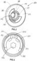
- the major components of a rotary recline mechanism 10 include a washer or retainer 20, an outer gear 30, an inner gear 70, a bearing 90, an eccentric element assembly 100 having wedges 102 and eccentric ring or carrier 120, a spring 170 and a rotating adjustment element 180. When assembled, these generally form the rotary recline mechanism 10.
- the washer or retainer 20 is generally configured to also fit around a hub 184 on the rotary adjustment element 180 thereby coupling all of the elements in FIG. 1 as described above together.
- the outer gear 30 may have a variety of styles, shapes and configurations depending upon the desired embodiment in which it is located, the outer gear 30 generally includes an outer portion 32 having an outer edge 34, an intermediate portion 40 which includes a tooth region 42 and an inner portion 50 having a center hub 56.
- the outer gear 30 illustrated in the Figures is to be generally used in what is commonly known as a five-door rotary recline mechanism. However, with other minor changes to the profile, that outer gear can be easily used in other rotary recline mechanisms with the present invention also being applicable.
- the outer gear 30 generally includes a first side 26 and a second side 28.
- the first side 26 may also be referred to as the inner face of the outer gear and the second side 28 may also be referred to as the outer face of the outer gear.
- the outer portion 32 generally includes an outer extent 33 having an outer edge 34.
- the outer edge 34 and outer extent 33 may be configured as desired to fit in a variety of different applications.
- the outer portion 32 also could be considered to having a first surface 36 and a second surface 38 which generally form planes.
- the intermediate portion 40 as described above generally includes the tooth region 42.
- the tooth region 42 generally includes female gear teeth 44 on the inner side 26 and male gear teeth 46 on the outer side 28.
- the female and male gear teeth 44, 46 are the result of stamping the gear teeth into the outer gear 30 such that when the outer gear 30 is formed and the gear cavity 48 defined by the intermediate portion 40 and inner portion 50 has female gear teeth 44 into which the inner gear 70 may be placed.
- the inner portion 50 may have a variety of styles, shapes and configurations depending upon the desired application of the outer gear 30.
- the inner portion 50 may be configured to be welded to other members including raised portions which act as weld surfaces for other forming techniques to configure the outer gear as desired to work in a rotary recline system 10.
- the inner portion generally includes a first portion 52 extending inwardly toward the center or axis of rotation 14 and a second optional portion 54 recessed from the first portion 52.
- the inner portion 50 also includes the center hub 56 which extends outwardly from the plane formed by the first portion 52 into the gear cavity 48 and in some embodiments, beyond the first surface 36 of the outer gear's inner face.
- the center hub 56 extends a set distance into the gear cavity 48 or beyond the gear cavity 48 and is generally configured to have an outer circumferential surface 58 and an inner circumferential surface 60.
- the inner circumferential surface 60 generally defines an axial opening with a specified diameter in the center hub 56 and ends in an end surface 64.
- the end surface 64 may be shaped to have various beveled surfaces as illustrated in the Figures.
- the center hub 56 also includes an end cap which is later removed and during the forming process, this end cap has a concave surface 69.
- the outer surface 28 of the outer gear 30 may also be configured around the area of the center hub 56 to have various bevels or other shapes as desired.
- the concave surface 69 may also be on the inside of the end cap 68 or both sides of the end cap 68 may include concave surfaces.
- the inner gear 70 generally includes an outer portion 72, a gear portion 78 with male gear teeth 80 and an axial hub 82 having an inner race 84.
- the inner gear 70 as described above generally fits within the gear cavity 48 formed by the outer gear 30.
- the male gear teeth 80 generally have one less or in some cases, two or less gear teeth than the female gear teeth 44 of the outer gear 30.
- the axial hub 82 formed by the inner gear 70 includes the inner race 84 against which the bearing 90 is placed.
- the bearing 90 may be allowed or configured to rotate freely against the inner race and in other embodiments, the bearing 90 can be press fit against the inner race 84.
- the bearing 90 generally includes an inner surface and an outer surface 94 wherein the outer surface 94 is configured to be engaged against the inner race 84.
- the bearing 90 also generally has a width similar to that of the axial hub 82 of the inner gear 70.
- the bearing 90 is generally formed as is well known in the art.
- An eccentric element assembly 100 is configured to fit within the bearing 90 specifically within the inner surface 92 and rotate therein against the inner surface 92 applying pressure to one area of the bearing 90.
- the eccentric element assembly 100 is generally formed from an eccentric ring or carrier 120 and wedges 102 placed between the carrier 120 and the inner surface 92 of the bearing 90.
- the wedges 102 are generally configured to have an outer face 104 which bear against the inner surface 92 of the bearing and an inner face 106 which bears against the carrier 120.
- the wedges 102 also have a wide end 108 and a narrow end 110 wherein the wide end 108 is configured to be in close proximity to the carrier tab 132 on the carrier 120.
- the wedges 102 may also further include notches 112 on the wide end 108.
- the carrier 120 generally includes a circumferential portion 122 having an inner surface 124, and an outer circumferential surface 126 that is interrupted by the outwardly extending carrier tab 132.
- the outer circumferential surface 126 includes an area of wedge load surfaces 128 in close proximity to the carrier tab 132.
- One or more drive tabs 130 extend from the circumferential portion 122 approximately parallel to the axis of rotation 14 which also acts generally as the center for the radius of the circumferential portion 122.
- the carrier tab 132 may be shaped in a variety of sizes, shapes and configurations but generally includes a carrier tab load surface 134 which is in close proximity of the inner surface 92 of the bearing 90.
- the carrier tab 132 and specifically the carrier tab load surface 134 is configured to support the inner surface 92 of the bearing 90 when a high load, such as a crash load, is seen by the recliner. This load tends to collapse the center area and the carrier tab 312 resists this collapse. More specifically, the carrier tab 132 may act as a brace between the bearing 90 and the hub 56 in high load situations to distribute the load and increase the load carrying capabilities to make the recliner stronger.
- the applied load is an eccentric load such that as the carrier tab rotates around inside of the bearing 90, the male teeth 80 of the inner gear and female gear teeth 44 of the outer gear 30 which are in approximate radial alignment with the carrier tab 132 wherein the radial alignment extends from the axis of rotation 14 through the carrier tab 132 are directly engaged. In comparison, the directly opposing male gear teeth 80 and female gear teeth 44 are disengaged as discussed above as the inner gear 70 has one less gear tooth than the outer gear 30.
- the eccentric load applied through the carrier tab 132 and wedges 102 moves the inner gear into contact with the outer gear eccentrically such that as the inner gear is driven into engagement with the outer gear in this eccentric fashion, the outer gear is forced to rotate relative to the inner gear and more specifically, as described above, the outer gear is driven approximately ten degrees radially about the axis of rotation for each rotation of the carrier 120 about the axis of rotation 14.
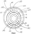
- the carrier 120 specifically the inner surface 124 includes at least one profiled inner portion 140.
- the addition of these profiled inner portions 140 means that the inner surface 124 of the carrier 120 is not a true circle having a defined radius from the axis of rotation 14 but instead, has areas in the profiled inner portions 140 that have slightly greater distances to the inner surface 124 from the axis of rotation 14 than the areas which are not considered profiled inner portions 140.
- the profiled inner portions include a first profiled area 150 and also an optional second profiled area 160.
- the first profiled area 150 occurs directly under the carrier tab 132 on the inner surface 124 and creates the anti-rock features of the current invention's rotary recline mechanism 10.
- the first profiled area 150 generally extends completely underneath the carrier tab 132 and typically extends for some distance to each side of the carrier tab 132 to under the wedges 102. Where the first profiled area ends, and the inner surface 124 returns to the set radius are the displaced inner load areas 154.
- the displaced inner load areas 154 are spaced on each side of the carrier tab 132 under the wedges 102.
- the second profiled area 160 is generally on the opposing side of the inner surface 124 from the first profiled area 150.
- the second profiled area 160 is optional but is illustrated in FIG. 8 as allowing for an additional grease pocket for grease to be located thereby improving the longevity of the carrier 120 when it spins within the bearing 90.
- the rotary recline mechanism 10 may further include springs or a spring 170 having a radial portion 172 and leg ends 174.
- the spring 170 is generally configured to locate the wedges 102 and hold the wedges 102 into the proper position between the carrier 120 and the bearing 90.
- the carrier 120 is driven in its rotational movement by the rotating adjustment element 180.
- the rotating adjustment element 180 generally includes an outer cover 182, a hub 184 extending from the outer cover 182 and female tooth shoulder 194.
- the female tooth shoulder 194 engages the drive tab 130 on the carrier 120 and as the rotating adjustment element rotates, the female tooth shoulder 194 engages the drive tab 130 forcing the carrier 120 to rotate within the bearing 90.
- the hub 184 on the rotating adjustment element 180 may further include a retainer ring groove 188 to which the retainer or washer 20 is coupled to assemble the complete mechanism together.
- the rotating adjustment element 180 may also include a race support 190 having a race surface 192.
- the race support 190 prevents the wedges 102 from being displaced from the wedge load surface area 128 on the carrier 120.
- the hub 184 may also include an axial hole 186 having a key stop into which a power drive mechanism is engaged to rotate the rotating adjustment element 180.
- the present invention provides a unique method of forming the outer gear 30.
- the outer gear 30 was formed of a mild steel such as a 4130 steel or other low carbon steel and then heat treated to make it high strength. While some manufacturers attempted to make the outer gear out of a stronger steel such a 550X, 550XF, or S700 steel having a higher carbon content, the problem was that due to the significant amount of forming that was required for the outer gear 30, the outer gear tended to crack in various places. Therefore, as of currently, no manufacturer has been able to form an outer gear out of a high carbon content steel such as a 550X steel.
- the present invention starts with a flat sheet of steel of high carbon content such as a 550X steel and then proceeds to process the steel through both a forging and forming process.
- a flat sheet of steel of high carbon content such as a 550X steel
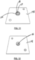
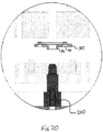
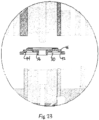
- the dies 200 use a convex die 202 to create a concave surface 69 illustrated in FIG. 11 . Therefore, as the hub 56 is being formed, the dies 200 specifically the convex die 202 punches out the center hub 56 with an end cap having a concave surface 69 which moves material from the center of the end cap 56 to the end surface 64 of the center hub 56.
- FIGS. 11, 12 and 13 only illustrate the forming of one concave surface 69 and on the inner side 26 of the outer gear 30, the opposing side of the end cap 68 or both sides of the end cap 68 may include concave surfaces 69.
- the end cap 68 may be punched from the metal sheet forming the outer gear 30.
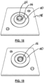
- the steps may vary after the center hub 56 is formed with the concave surface 69 and end cap 68, the present invention in its exemplar steps forms the profile generally of the inner portion 50 of the outer gear 30.
- the profile of the inner portion 50 illustrated in FIGS. 15 and 16 is exemplary and could vary depending upon the desired configuration.
- FIG. 20 generally illustrates an exemplary set of dies 200 used to provide the formation of the profiled inner portion 50 as well as the additional forming steps to the center hub 56.
- FIGS. 21 and 22 further illustrate forming of the outer portion 32 and intermediate portion 40 specifically the tooth region 42.
- the dies 200 would generally support the formed center hub and semi-pierce the metal sheet at the intermediate portion 40 to form the tooth region 42 having a female gear teeth 44 and male gear teeth 46.
- the dies 200 may then continue to close to punch the outer gear 30 out from the metal sheet forming the outer edge 34 and outer extent 33.
- the finalized gears are illustrated in FIGS. 21 and 22 with exemplary dies 200 used thereby to form in FIG. 23 .
Landscapes
- Engineering & Computer Science (AREA)
- Mechanical Engineering (AREA)
- Aviation & Aerospace Engineering (AREA)
- Transportation (AREA)
- Chairs For Special Purposes, Such As Reclining Chairs (AREA)
- Seats For Vehicles (AREA)
- Gears, Cams (AREA)
Claims (8)
- Neigungsmechanismus für einen Fahrzeugsitz, der Folgendes umfasst:eine Unterlegscheibe oder einen Halter (20),ein äußeres Zahnrad (30), das eine erste Seite (26), eine zweite Seite (28) und einen Zwischenabschnitt (40) mit einem Zahnbereich (42) aufweist, wobei der Zahnbereich (42) Zahnradaussparungen (44) an der ersten Seite (26) und Zahnradvorsprünge (46) an der zweiten Seite (28) aufweist,ein inneres Zahnrad (70), das einen äußeren Abschnitt (72), einen Zahnradabschnitt (78) mit Zahnradvorsprüngen (80) und eine axiale Nabe (82) mit einem Innenring (84) aufweist,eine Feder (170),einen exzentrischen Träger (120) mit einem umlaufenden Teil, angeordnet um eine Achse und umfassend eine innere umlaufende Oberfläche und eine äußere umlaufende Oberfläche (126),eine Trägernase (132), die sich radial von der äußeren umlaufenden Oberfläche erstreckt, und eine Antriebsnase (130), die von der Achse beabstandet ist und sich entlang derselben erstreckt und wobei die innere umlaufende Oberfläche ungefähr kreisförmig, aber nicht kreisförmig ist,ein rotierendes Einstellelement (180), das eine äußere Abdeckung (182), eine umlaufende Nabe (186), die sich von der äußeren Abdeckung (182) erstreckt, und eine Zahnschulteraussparung (193) aufweist, die die Antriebsnase (130) an dem exzentrischen Träger (120) in Eingriff nimmt, wobei die äußere umlaufende Oberfläche (126) des Trägers (120) einen Bereich von Keilladeflächen (128) in nächster Nähe zu der Trägernase (132) aufweist, ein Lager (90) mit einer inneren und äußeren Oberfläche (94), wobei eine durch den exzentrischen Träger (120) und zwischen dem Träger (120) und der inneren Oberfläche (92) des Lagers (90) platzierte Keile (102) gebildete exzentrische Anordnung (100) dazu ausgestaltet ist, in die innere Oberfläche (92) des Lagers (92) zu passen und sich darin unter Ausübung von Druck auf einen Bereich des Lagers (90) gegen die innere Oberfläche (92) zu drehen, wobei die äußere Oberfläche (94) in den Innenring (84) eingreift, wobei die Trägernase (132) eine Trägerlastoberfläche (134) aufweist, die in nächster Nähe der inneren Oberfläche (92) des Lagers (90) liegt, wobei die Trägerlastoberfläche (134) dazu ausgestaltet ist, die innere Oberfläche (92) des Lagers (90) unter hohen Lastbedingungen zu stützen, wobei sich die Trägernasenseitenoberflächen (136) zwischen der Trägerlastoberfläche (134) und der äußeren umlaufenden Oberfläche (126) des Trägers (120) erstrecken; undein Paar der Keile (102), befindlich an einander gegenüberliegenden Seiten von und nahe der Trägernase (132) und wobei jeder der Keile (102) eine äußere Fläche und eine innere Fläche umfasst, wobei die äußere Fläche in die innere Oberfläche des Lagers eingreift und die innere Fläche in die äußere umlaufende Oberfläche des Trägers eingreift;wobei die Keile (102) zwischen dem Träger (120) und der inneren Oberfläche (92) des Lagers (90) platziert sind, wobei die Keile (102) ein breites Ende (108) und ein schmales Ende (110) haben, wobei das breite Ende (108) dazu ausgestaltet ist, in nächster Nähe der Trägernase (132) an dem Träger (120) zu sein,wobei die innere umlaufende Oberfläche einen ersten profilierten Teil (150) umfasst, der annähernd radial um die Trägernase zentriert ist, wobei sich der erste profilierte Bereich (150) vollständig unter der Trägernase (132) erstreckt und sich über eine gewisse Strecke beiderseits der Trägernase (132) unter das Paar Keile (102) erstreckt, wobei verschobene innere Lastbereiche (154) unter dem Paar Keile (102) sind und zu beiden Seiten der Trägernase (132) beabstandet sind, wo der erste profilierte Bereich (150) endet und die innere Oberfläche (124) zu dem eingestellten Radius zurückkehrt, wobei der Träger (120) in dem ersten profilierten Teil (150) die umlaufende Nabe (186) nicht in Eingriff nimmt,wobei die Unterlegscheibe oder der Halter (20) dazu ausgestaltet ist, um die Nabe (186) an dem rotierenden Einstellelement (180) zu passen, wodurch alle Elemente zusammengekoppelt werden.
- Neigungsmechanismus nach Anspruch 1, wobei sich der Großteil der inneren umlaufenden Oberfläche um die Achse bei einem ersten Abstand von der Achse erstreckt, und wobei die innere umlaufende Oberfläche zumindest einen profilierten Teil umfasst und wobei die radialen Abstände entlang des profilierten Teils von der Achse größer als der erste Abstand sind.
- Neigungsmechanismus nach Anspruch 1, wobei die innere umlaufende Oberfläche einen ersten profilierten Teil mit einer bogenförmigen Form umfasst und wobei das Zentrum der bogenförmigen Form nicht die Achse ist.
- Neigungsmechanismus nach Anspruch 3, wobei die innere umlaufende Oberfläche einen zweiten profilierten Teil umfasst, der annähernd gegenüberliegend dem ersten profilierten Teil entlang der inneren umlaufenden Oberfläche ist.
- Neigungsmechanismus nach Anspruch 3, wobei der erste profilierte Teil zwei einander gegenüberliegende Enden umfasst, wobei die innere umlaufende Oberfläche davon, mehr als den festgelegten Abstand von der Achse beabstandet zu sein, dazu übergeht, gleich dem festgelegten Abstand von der Achse beabstandet zu sein.
- Neigungsmechanismus nach Anspruch 1, wobei die innere umlaufende Oberfläche einen zweiten profilierten Teil umfasst, der sich radial gegenüberliegend der Trägernase entlang der inneren umlaufenden Oberfläche befindet und wobei der zweite profilierte Teil nicht in die umlaufende Nabe eingreift.
- Neigungsmechanismus nach Anspruch 1, wobei die innere umlaufende Oberfläche einen ersten profilierten Teil umfasst, der eine bogenförmige Form hat und wobei das Zentrum der bogenförmigen Form nicht die Achse ist und wobei die innere umlaufende Oberfläche einen zweiten profilierten Teil annähernd gegenüberliegend dem ersten profilierten Teil entlang der inneren umlaufenden Oberfläche umfasst.
- Verfahren zur Bildung eines äußeren Zahnrads für einen Sitzneigungsmechanismus, wobei das Verfahren Folgendes umfasst:Bereitstellen eines Metallblechs;Bilden einer eingeschlossenen Nabe mit einer Endkappe mit zumindest einer konkaven Oberfläche;wobei sich die konkave Oberfläche in einer Richtung zur eingeschlossenen Nabe erstreckt;wobei der Schritt des Bildens einer eingeschlossenen Nabe mit einer Endkappe mit mindestens einer konkaven Oberfläche ferner die Schritte des partiellen Bildens der Nabe und des abschließenden Bildens der Nabe aufweist, während eine konkave Oberfläche in der Endkappe geschaffen wird, um Material von der Endkappe zu der Nabe zu bewegen,wobei die konkave Oberfläche durch ein konvexes Gesenk gebildet wird, wobei Material von einer Mitte der Endkappe zu einer Endoberfläche der eingeschlossenen Nabe fließt;Entfernen der Endkappe von der eingeschlossenen Nabe auf dem Metallblech zum Bilden einer Nabe;Bilden von inneren Ringen am Metallblech;Bilden von äußeren angefasten Kanten an der Nabe an dem Metallblech;Bilden eines Zwischenelements, umfassend Zahnradzähne, wobei die Zahnradzähne Zahnaussparungen (44) an einer inneren Seite (26) und Zahnvorsprünge (46) an einer äußeren Seite (28) am Zwischenelement umfassen; undAusstanzen eines äußeren Zahnrads aus dem Metallblech, das einen äußeren Teil bildet, der sich vom Zwischenelement zu einer äußeren Kante erstreckt.
Applications Claiming Priority (2)
| Application Number | Priority Date | Filing Date | Title |
|---|---|---|---|
| US23332109P | 2009-08-12 | 2009-08-12 | |
| PCT/US2010/045308 WO2011019904A1 (en) | 2009-08-12 | 2010-08-12 | Continuously engaged recliner freeplay system and fine-blanked gear hub |
Publications (4)
| Publication Number | Publication Date |
|---|---|
| EP2464537A1 EP2464537A1 (de) | 2012-06-20 |
| EP2464537A4 EP2464537A4 (de) | 2018-01-17 |
| EP2464537B1 EP2464537B1 (de) | 2020-12-30 |
| EP2464537B2 true EP2464537B2 (de) | 2024-06-12 |
Family
ID=43586483
Family Applications (1)
| Application Number | Title | Priority Date | Filing Date |
|---|---|---|---|
| EP10808752.9A Active EP2464537B2 (de) | 2009-08-12 | 2010-08-12 | Kontinuierlich angetriebenes neigungsfreispielsystem und feingestanzte getriebenabe dafür |
Country Status (6)
| Country | Link |
|---|---|
| US (1) | US8931842B2 (de) |
| EP (1) | EP2464537B2 (de) |
| JP (2) | JP2013501683A (de) |
| KR (1) | KR101806824B1 (de) |
| CN (1) | CN102481862B (de) |
| WO (1) | WO2011019904A1 (de) |
Families Citing this family (20)
| Publication number | Priority date | Publication date | Assignee | Title |
|---|---|---|---|---|
| CN103561882B (zh) * | 2011-05-26 | 2015-11-25 | 约翰逊控股公司 | 冲压方法以及由此制备的部件 |
| DE102013000636A1 (de) * | 2013-01-16 | 2014-07-17 | Sitech Sitztechnik Gmbh | Hochtragfähige Verstelleinrichtung, insbesondere Sitzversteller auf FeMn-Basis |
| KR101569625B1 (ko) | 2013-06-27 | 2015-11-17 | 주식회사다스 | 차량용 시트의 리클라이너 |
| KR101635354B1 (ko) * | 2016-03-09 | 2016-07-01 | 대원정밀공업(주) | 파워 리클라이너 장치 |
| KR102001507B1 (ko) * | 2017-12-26 | 2019-07-18 | 현대트랜시스(주) | 차량의 시트 리클라이너 |
| IT201800004672A1 (it) * | 2018-04-18 | 2019-10-18 | Dispositivo di reclinazione per un sedile di veicolo | |
| KR102126459B1 (ko) * | 2018-11-28 | 2020-06-25 | 현대트랜시스(주) | 차량 시트용 리클라이닝 장치 |
| US11845367B2 (en) | 2019-04-18 | 2023-12-19 | Fisher & Company, Incorporated | Recliner heart having lubricant member |
| KR102236705B1 (ko) | 2019-11-29 | 2021-04-06 | 주식회사 다스 | 자동차용 시트의 리클라이너 |
| US11607976B2 (en) | 2020-03-06 | 2023-03-21 | Fisher & Company, Incorporated | Recliner mechanism having bracket |
| CN114287762B (zh) * | 2020-10-07 | 2024-01-30 | 大圆精密工业株式会社 | 电动躺椅 |
| KR102442453B1 (ko) * | 2020-11-10 | 2022-09-13 | 대원정밀공업(주) | 파워 리클라이너 |
| KR102216952B1 (ko) * | 2020-10-07 | 2021-02-19 | 대원정밀공업(주) | 파워 리클라이너 |
| KR102905589B1 (ko) * | 2020-10-14 | 2025-12-30 | 현대트랜시스 주식회사 | 시트 리클라이닝 장치 |
| US11766957B2 (en) | 2021-02-16 | 2023-09-26 | Fisher & Company, Incorporated | Release mechanism for seat recliner assembly |
| US11897372B2 (en) | 2021-05-06 | 2024-02-13 | Fisher & Company, Incorporated | Recliner heart having biasing members |
| US11850975B2 (en) | 2021-06-11 | 2023-12-26 | Fisher & Company, Incorporated | Vehicle seat recliner mechanism with welded spring |
| KR102542571B1 (ko) | 2021-10-15 | 2023-06-12 | 현대트랜시스 주식회사 | 차량의 리클라이너 |
| JP7790964B2 (ja) * | 2021-12-23 | 2025-12-23 | 株式会社今仙電機製作所 | リクライニング装置 |
| KR20240020972A (ko) * | 2022-08-09 | 2024-02-16 | 현대트랜시스 주식회사 | 차량 시트용 리클라이너 |
Citations (1)
| Publication number | Priority date | Publication date | Assignee | Title |
|---|---|---|---|---|
| US3964326A (en) † | 1973-12-17 | 1976-06-22 | Borg-Warner Corporation | One piece stamped pulley |
Family Cites Families (17)
| Publication number | Priority date | Publication date | Assignee | Title |
|---|---|---|---|---|
| US2072308A (en) * | 1934-05-16 | 1937-03-02 | Frank R Labin | Method of making gear wheels |
| US4254540A (en) * | 1978-09-27 | 1981-03-10 | William Bilak | Stamped bevel gear |
| DE3624018C2 (de) * | 1986-07-16 | 1998-07-02 | Keiper Gmbh & Co | Lehnenneigungseinstellbeschlag für Sitze, insbesondere Kraftfahrzeugsitze |
| DE3705116C2 (de) * | 1987-02-18 | 1996-08-14 | Keiper Recaro Gmbh Co | Verstellbeschlag für Sitze mit neigungsveränderbarer Rückenlehne |
| JPH0396426U (de) * | 1990-01-24 | 1991-10-02 | ||
| JP2632620B2 (ja) * | 1992-01-14 | 1997-07-23 | 大岡技研株式会社 | 歯車製品 |
| CH686236A5 (de) | 1992-03-26 | 1996-02-15 | Schmid Holding Ag | Verfahren zur Herstellung von Zahnscheiben, insbesondere fuer eine Autositz-Verstellung. |
| DE19938666C5 (de) * | 1999-08-14 | 2008-01-03 | Keiper Gmbh & Co.Kg | Verstellbeschlag für Sitze mit neigungseinstellbarer Lehne, insbesondere für Kraftfahzeugsitze |
| JP2002172451A (ja) | 2000-12-06 | 2002-06-18 | Toyota Motor Corp | 逆テーパ歯形を有する歯形製品の製造方法 |
| DE10327103B4 (de) * | 2003-06-12 | 2007-12-06 | C. Rob. Hammerstein Gmbh & Co. Kg | Untersetzungsgetriebe, insbesondere für eine Verstellvorrichtung eines Kraftfahrzeugsitzes |
| KR100549199B1 (ko) * | 2003-11-26 | 2006-02-02 | 주식회사다스 | 컨티뉴즐리타입 자동차용 시트 리클라이닝장치 |
| DE102004013272B3 (de) * | 2004-03-18 | 2006-01-26 | Faurecia Autositze Gmbh & Co. Kg | Neigungsverstellbeschlag für die Rückenlehne eines Kraftfahrzeugsitzes |
| DE102005026658B3 (de) | 2005-06-09 | 2006-11-02 | Faurecia Autositze Gmbh & Co. Kg | Neigungsverstellbeschlag für die Rückenlehne eines Kraftfahrzeugsitzes |
| DE102005052781B3 (de) * | 2005-11-05 | 2006-12-14 | Faurecia Autositze Gmbh & Co. Kg | Neigungsverstellbeschlag für die Rückenlehne eines Kraftfahrzeugsitzes |
| JP4831308B2 (ja) | 2005-12-16 | 2011-12-07 | アイシン精機株式会社 | 車両用シートリクライニング装置 |
| PL2107977T3 (pl) * | 2007-01-04 | 2016-11-30 | Urządzenie do przestawiania siedzenia pojazdu | |
| JP4328372B2 (ja) * | 2007-09-07 | 2009-09-09 | 株式会社ピーエヌ | コアメタルの製造方法とコアメタルとインジェクションギヤ |
-
2010
- 2010-08-12 KR KR1020127006431A patent/KR101806824B1/ko active Active
- 2010-08-12 US US13/389,459 patent/US8931842B2/en active Active
- 2010-08-12 CN CN201080039797.6A patent/CN102481862B/zh active Active
- 2010-08-12 WO PCT/US2010/045308 patent/WO2011019904A1/en not_active Ceased
- 2010-08-12 JP JP2012524866A patent/JP2013501683A/ja active Pending
- 2010-08-12 EP EP10808752.9A patent/EP2464537B2/de active Active
-
2015
- 2015-03-17 JP JP2015052906A patent/JP6111279B2/ja active Active
Patent Citations (1)
| Publication number | Priority date | Publication date | Assignee | Title |
|---|---|---|---|---|
| US3964326A (en) † | 1973-12-17 | 1976-06-22 | Borg-Warner Corporation | One piece stamped pulley |
Non-Patent Citations (1)
| Title |
|---|
| ANONYMOUS: "FEINTOOLING INFORMATION", FEINTOOL, 1996, pages 1 - 48, XP055850787 † |
Also Published As
| Publication number | Publication date |
|---|---|
| EP2464537B1 (de) | 2020-12-30 |
| EP2464537A4 (de) | 2018-01-17 |
| JP6111279B2 (ja) | 2017-04-05 |
| JP2013501683A (ja) | 2013-01-17 |
| CN102481862A (zh) | 2012-05-30 |
| JP2015145236A (ja) | 2015-08-13 |
| CN102481862B (zh) | 2015-08-26 |
| KR20120049333A (ko) | 2012-05-16 |
| US20120169102A1 (en) | 2012-07-05 |
| KR101806824B1 (ko) | 2017-12-11 |
| WO2011019904A1 (en) | 2011-02-17 |
| EP2464537A1 (de) | 2012-06-20 |
| US8931842B2 (en) | 2015-01-13 |
Similar Documents
| Publication | Publication Date | Title |
|---|---|---|
| EP2464537B1 (de) | Kontinuierlich angetriebenes neigungsfreispielsystem und feingestanzte getriebenabe dafür | |
| KR101354596B1 (ko) | 차량 시트용 피팅 | |
| US8998328B2 (en) | Fitting for a vehicle seat | |
| EP2550177B1 (de) | Verfahren zur herstellung eines fahrzeugsitz-beschlags | |
| US8905479B2 (en) | Fitting for a vehicle seat | |
| WO2011029520A2 (de) | Beschlag für einen fahrzeugsitz | |
| US20130220049A1 (en) | Method for Producing High-Strength Components by Means of Adiabatic Blanking | |
| US20090066137A1 (en) | Reclining Device | |
| KR20130003035A (ko) | 차량 시트용 피팅 | |
| CN103813936B (zh) | 车辆座椅装配件的制造方法 | |
| CN107178562B (zh) | 离合器环形齿轮组件及其构造方法 | |
| DE102011112426B4 (de) | Beschlag für einen Fahrzeugsitz und Fahrzeugsitz | |
| WO2011154079A1 (de) | Beschlag für einen fahrzeugsitz |
Legal Events
| Date | Code | Title | Description |
|---|---|---|---|
| PUAI | Public reference made under article 153(3) epc to a published international application that has entered the european phase |
Free format text: ORIGINAL CODE: 0009012 |
|
| 17P | Request for examination filed |
Effective date: 20120220 |
|
| AK | Designated contracting states |
Kind code of ref document: A1 Designated state(s): AL AT BE BG CH CY CZ DE DK EE ES FI FR GB GR HR HU IE IS IT LI LT LU LV MC MK MT NL NO PL PT RO SE SI SK SM TR |
|
| DAX | Request for extension of the european patent (deleted) | ||
| RAP1 | Party data changed (applicant data changed or rights of an application transferred) |
Owner name: JOHNSON CONTROLS TECHNOLOGY COMPANY |
|
| RA4 | Supplementary search report drawn up and despatched (corrected) |
Effective date: 20171214 |
|
| RIC1 | Information provided on ipc code assigned before grant |
Ipc: B60N 2/02 20060101AFI20171208BHEP Ipc: B60N 2/225 20060101ALI20171208BHEP Ipc: B21D 53/28 20060101ALI20171208BHEP |
|
| RAP1 | Party data changed (applicant data changed or rights of an application transferred) |
Owner name: ADIENT LUXEMBOURG HOLDING S.A R.L. |
|
| GRAP | Despatch of communication of intention to grant a patent |
Free format text: ORIGINAL CODE: EPIDOSNIGR1 |
|
| STAA | Information on the status of an ep patent application or granted ep patent |
Free format text: STATUS: GRANT OF PATENT IS INTENDED |
|
| INTG | Intention to grant announced |
Effective date: 20200723 |
|
| RIN1 | Information on inventor provided before grant (corrected) |
Inventor name: KAPUSKY, MICHAEL, J. Inventor name: BITTNER, MICHAEL, R. Inventor name: PROFOZICH, SCOTT, A. Inventor name: HIEMSTRA, BRUCE, A. |
|
| GRAS | Grant fee paid |
Free format text: ORIGINAL CODE: EPIDOSNIGR3 |
|
| GRAA | (expected) grant |
Free format text: ORIGINAL CODE: 0009210 |
|
| STAA | Information on the status of an ep patent application or granted ep patent |
Free format text: STATUS: THE PATENT HAS BEEN GRANTED |
|
| AK | Designated contracting states |
Kind code of ref document: B1 Designated state(s): AL AT BE BG CH CY CZ DE DK EE ES FI FR GB GR HR HU IE IS IT LI LT LU LV MC MK MT NL NO PL PT RO SE SI SK SM TR |
|
| REG | Reference to a national code |
Ref country code: GB Ref legal event code: FG4D |
|
| RIN1 | Information on inventor provided before grant (corrected) |
Inventor name: BITTNER, MICHAEL, R. Inventor name: HIEMSTRA, BRUCE, A. Inventor name: KAPUSKY, MICHAEL, J. Inventor name: PROFOZICH, SCOTT, A. |
|
| REG | Reference to a national code |
Ref country code: AT Ref legal event code: REF Ref document number: 1349610 Country of ref document: AT Kind code of ref document: T Effective date: 20210115 |
|
| REG | Reference to a national code |
Ref country code: DE Ref legal event code: R096 Ref document number: 602010066258 Country of ref document: DE |
|
| REG | Reference to a national code |
Ref country code: IE Ref legal event code: FG4D |
|
| PG25 | Lapsed in a contracting state [announced via postgrant information from national office to epo] |
Ref country code: GR Free format text: LAPSE BECAUSE OF FAILURE TO SUBMIT A TRANSLATION OF THE DESCRIPTION OR TO PAY THE FEE WITHIN THE PRESCRIBED TIME-LIMIT Effective date: 20210331 Ref country code: FI Free format text: LAPSE BECAUSE OF FAILURE TO SUBMIT A TRANSLATION OF THE DESCRIPTION OR TO PAY THE FEE WITHIN THE PRESCRIBED TIME-LIMIT Effective date: 20201230 Ref country code: NO Free format text: LAPSE BECAUSE OF FAILURE TO SUBMIT A TRANSLATION OF THE DESCRIPTION OR TO PAY THE FEE WITHIN THE PRESCRIBED TIME-LIMIT Effective date: 20210330 |
|
| REG | Reference to a national code |
Ref country code: AT Ref legal event code: MK05 Ref document number: 1349610 Country of ref document: AT Kind code of ref document: T Effective date: 20201230 |
|
| PG25 | Lapsed in a contracting state [announced via postgrant information from national office to epo] |
Ref country code: LV Free format text: LAPSE BECAUSE OF FAILURE TO SUBMIT A TRANSLATION OF THE DESCRIPTION OR TO PAY THE FEE WITHIN THE PRESCRIBED TIME-LIMIT Effective date: 20201230 Ref country code: SE Free format text: LAPSE BECAUSE OF FAILURE TO SUBMIT A TRANSLATION OF THE DESCRIPTION OR TO PAY THE FEE WITHIN THE PRESCRIBED TIME-LIMIT Effective date: 20201230 Ref country code: BG Free format text: LAPSE BECAUSE OF FAILURE TO SUBMIT A TRANSLATION OF THE DESCRIPTION OR TO PAY THE FEE WITHIN THE PRESCRIBED TIME-LIMIT Effective date: 20210330 |
|
| REG | Reference to a national code |
Ref country code: NL Ref legal event code: MP Effective date: 20201230 |
|
| PG25 | Lapsed in a contracting state [announced via postgrant information from national office to epo] |
Ref country code: HR Free format text: LAPSE BECAUSE OF FAILURE TO SUBMIT A TRANSLATION OF THE DESCRIPTION OR TO PAY THE FEE WITHIN THE PRESCRIBED TIME-LIMIT Effective date: 20201230 |
|
| REG | Reference to a national code |
Ref country code: LT Ref legal event code: MG9D |
|
| PG25 | Lapsed in a contracting state [announced via postgrant information from national office to epo] |
Ref country code: LT Free format text: LAPSE BECAUSE OF FAILURE TO SUBMIT A TRANSLATION OF THE DESCRIPTION OR TO PAY THE FEE WITHIN THE PRESCRIBED TIME-LIMIT Effective date: 20201230 Ref country code: PT Free format text: LAPSE BECAUSE OF FAILURE TO SUBMIT A TRANSLATION OF THE DESCRIPTION OR TO PAY THE FEE WITHIN THE PRESCRIBED TIME-LIMIT Effective date: 20210430 Ref country code: RO Free format text: LAPSE BECAUSE OF FAILURE TO SUBMIT A TRANSLATION OF THE DESCRIPTION OR TO PAY THE FEE WITHIN THE PRESCRIBED TIME-LIMIT Effective date: 20201230 Ref country code: SK Free format text: LAPSE BECAUSE OF FAILURE TO SUBMIT A TRANSLATION OF THE DESCRIPTION OR TO PAY THE FEE WITHIN THE PRESCRIBED TIME-LIMIT Effective date: 20201230 Ref country code: NL Free format text: LAPSE BECAUSE OF FAILURE TO SUBMIT A TRANSLATION OF THE DESCRIPTION OR TO PAY THE FEE WITHIN THE PRESCRIBED TIME-LIMIT Effective date: 20201230 Ref country code: CZ Free format text: LAPSE BECAUSE OF FAILURE TO SUBMIT A TRANSLATION OF THE DESCRIPTION OR TO PAY THE FEE WITHIN THE PRESCRIBED TIME-LIMIT Effective date: 20201230 Ref country code: EE Free format text: LAPSE BECAUSE OF FAILURE TO SUBMIT A TRANSLATION OF THE DESCRIPTION OR TO PAY THE FEE WITHIN THE PRESCRIBED TIME-LIMIT Effective date: 20201230 |
|
| PG25 | Lapsed in a contracting state [announced via postgrant information from national office to epo] |
Ref country code: PL Free format text: LAPSE BECAUSE OF FAILURE TO SUBMIT A TRANSLATION OF THE DESCRIPTION OR TO PAY THE FEE WITHIN THE PRESCRIBED TIME-LIMIT Effective date: 20201230 Ref country code: AT Free format text: LAPSE BECAUSE OF FAILURE TO SUBMIT A TRANSLATION OF THE DESCRIPTION OR TO PAY THE FEE WITHIN THE PRESCRIBED TIME-LIMIT Effective date: 20201230 |
|
| PG25 | Lapsed in a contracting state [announced via postgrant information from national office to epo] |
Ref country code: IS Free format text: LAPSE BECAUSE OF FAILURE TO SUBMIT A TRANSLATION OF THE DESCRIPTION OR TO PAY THE FEE WITHIN THE PRESCRIBED TIME-LIMIT Effective date: 20210430 |
|
| REG | Reference to a national code |
Ref country code: DE Ref legal event code: R026 Ref document number: 602010066258 Country of ref document: DE |
|
| PLBI | Opposition filed |
Free format text: ORIGINAL CODE: 0009260 |
|
| PLAB | Opposition data, opponent's data or that of the opponent's representative modified |
Free format text: ORIGINAL CODE: 0009299OPPO |
|
| PLAX | Notice of opposition and request to file observation + time limit sent |
Free format text: ORIGINAL CODE: EPIDOSNOBS2 |
|
| PG25 | Lapsed in a contracting state [announced via postgrant information from national office to epo] |
Ref country code: IT Free format text: LAPSE BECAUSE OF FAILURE TO SUBMIT A TRANSLATION OF THE DESCRIPTION OR TO PAY THE FEE WITHIN THE PRESCRIBED TIME-LIMIT Effective date: 20201230 Ref country code: AL Free format text: LAPSE BECAUSE OF FAILURE TO SUBMIT A TRANSLATION OF THE DESCRIPTION OR TO PAY THE FEE WITHIN THE PRESCRIBED TIME-LIMIT Effective date: 20201230 |
|
| 26 | Opposition filed |
Opponent name: FEINTOOL AG Effective date: 20210930 |
|
| REG | Reference to a national code |
Ref country code: DE Ref legal event code: R081 Ref document number: 602010066258 Country of ref document: DE Owner name: KEIPER SEATING MECHANISMS CO., LTD., CN Free format text: FORMER OWNER: ADIENT YANFENG SEATING MECHANISMS CO., LTD., SHANGHAI, CN Ref country code: DE Ref legal event code: R081 Ref document number: 602010066258 Country of ref document: DE Owner name: KEIPER SEATING MECHANISMS CO., LTD., CN Free format text: FORMER OWNER: ADIENT LUXEMBOURG HOLDING S.A R.L., LUXEMBOURG, LU |
|
| R26 | Opposition filed (corrected) |
Opponent name: FEINTOOL INTERNATIONAL HOLDING AG Effective date: 20210930 |
|
| PG25 | Lapsed in a contracting state [announced via postgrant information from national office to epo] |
Ref country code: DK Free format text: LAPSE BECAUSE OF FAILURE TO SUBMIT A TRANSLATION OF THE DESCRIPTION OR TO PAY THE FEE WITHIN THE PRESCRIBED TIME-LIMIT Effective date: 20201230 Ref country code: ES Free format text: LAPSE BECAUSE OF FAILURE TO SUBMIT A TRANSLATION OF THE DESCRIPTION OR TO PAY THE FEE WITHIN THE PRESCRIBED TIME-LIMIT Effective date: 20201230 |
|
| PLBB | Reply of patent proprietor to notice(s) of opposition received |
Free format text: ORIGINAL CODE: EPIDOSNOBS3 |
|
| PG25 | Lapsed in a contracting state [announced via postgrant information from national office to epo] |
Ref country code: SI Free format text: LAPSE BECAUSE OF FAILURE TO SUBMIT A TRANSLATION OF THE DESCRIPTION OR TO PAY THE FEE WITHIN THE PRESCRIBED TIME-LIMIT Effective date: 20201230 |
|
| REG | Reference to a national code |
Ref country code: CH Ref legal event code: PL |
|
| PG25 | Lapsed in a contracting state [announced via postgrant information from national office to epo] |
Ref country code: MC Free format text: LAPSE BECAUSE OF FAILURE TO SUBMIT A TRANSLATION OF THE DESCRIPTION OR TO PAY THE FEE WITHIN THE PRESCRIBED TIME-LIMIT Effective date: 20201230 |
|
| REG | Reference to a national code |
Ref country code: BE Ref legal event code: MM Effective date: 20210831 |
|
| GBPC | Gb: european patent ceased through non-payment of renewal fee |
Effective date: 20210812 |
|
| PG25 | Lapsed in a contracting state [announced via postgrant information from national office to epo] |
Ref country code: LI Free format text: LAPSE BECAUSE OF NON-PAYMENT OF DUE FEES Effective date: 20210831 Ref country code: CH Free format text: LAPSE BECAUSE OF NON-PAYMENT OF DUE FEES Effective date: 20210831 |
|
| PG25 | Lapsed in a contracting state [announced via postgrant information from national office to epo] |
Ref country code: IS Free format text: LAPSE BECAUSE OF FAILURE TO SUBMIT A TRANSLATION OF THE DESCRIPTION OR TO PAY THE FEE WITHIN THE PRESCRIBED TIME-LIMIT Effective date: 20210430 Ref country code: LU Free format text: LAPSE BECAUSE OF NON-PAYMENT OF DUE FEES Effective date: 20210812 |
|
| PG25 | Lapsed in a contracting state [announced via postgrant information from national office to epo] |
Ref country code: IE Free format text: LAPSE BECAUSE OF NON-PAYMENT OF DUE FEES Effective date: 20210812 Ref country code: GB Free format text: LAPSE BECAUSE OF NON-PAYMENT OF DUE FEES Effective date: 20210812 Ref country code: BE Free format text: LAPSE BECAUSE OF NON-PAYMENT OF DUE FEES Effective date: 20210831 |
|
| RAP2 | Party data changed (patent owner data changed or rights of a patent transferred) |
Owner name: KEIPER SEATING MECHANISMS CO., LTD. |
|
| REG | Reference to a national code |
Ref country code: DE Ref legal event code: R082 Ref document number: 602010066258 Country of ref document: DE Representative=s name: KUTZENBERGER WOLFF & PARTNER PATENTANWALTSPART, DE |
|
| PG25 | Lapsed in a contracting state [announced via postgrant information from national office to epo] |
Ref country code: HU Free format text: LAPSE BECAUSE OF FAILURE TO SUBMIT A TRANSLATION OF THE DESCRIPTION OR TO PAY THE FEE WITHIN THE PRESCRIBED TIME-LIMIT; INVALID AB INITIO Effective date: 20100812 Ref country code: CY Free format text: LAPSE BECAUSE OF FAILURE TO SUBMIT A TRANSLATION OF THE DESCRIPTION OR TO PAY THE FEE WITHIN THE PRESCRIBED TIME-LIMIT Effective date: 20201230 |
|
| PG25 | Lapsed in a contracting state [announced via postgrant information from national office to epo] |
Ref country code: SM Free format text: LAPSE BECAUSE OF FAILURE TO SUBMIT A TRANSLATION OF THE DESCRIPTION OR TO PAY THE FEE WITHIN THE PRESCRIBED TIME-LIMIT Effective date: 20201230 |
|
| APBM | Appeal reference recorded |
Free format text: ORIGINAL CODE: EPIDOSNREFNO |
|
| APBP | Date of receipt of notice of appeal recorded |
Free format text: ORIGINAL CODE: EPIDOSNNOA2O |
|
| APAH | Appeal reference modified |
Free format text: ORIGINAL CODE: EPIDOSCREFNO |
|
| APBU | Appeal procedure closed |
Free format text: ORIGINAL CODE: EPIDOSNNOA9O |
|
| PG25 | Lapsed in a contracting state [announced via postgrant information from national office to epo] |
Ref country code: MK Free format text: LAPSE BECAUSE OF FAILURE TO SUBMIT A TRANSLATION OF THE DESCRIPTION OR TO PAY THE FEE WITHIN THE PRESCRIBED TIME-LIMIT Effective date: 20201230 |
|
| PUAH | Patent maintained in amended form |
Free format text: ORIGINAL CODE: 0009272 |
|
| STAA | Information on the status of an ep patent application or granted ep patent |
Free format text: STATUS: PATENT MAINTAINED AS AMENDED |
|
| 27A | Patent maintained in amended form |
Effective date: 20240612 |
|
| AK | Designated contracting states |
Kind code of ref document: B2 Designated state(s): AL AT BE BG CH CY CZ DE DK EE ES FI FR GB GR HR HU IE IS IT LI LT LU LV MC MK MT NL NO PL PT RO SE SI SK SM TR |
|
| REG | Reference to a national code |
Ref country code: DE Ref legal event code: R102 Ref document number: 602010066258 Country of ref document: DE |
|
| PG25 | Lapsed in a contracting state [announced via postgrant information from national office to epo] |
Ref country code: TR Free format text: LAPSE BECAUSE OF FAILURE TO SUBMIT A TRANSLATION OF THE DESCRIPTION OR TO PAY THE FEE WITHIN THE PRESCRIBED TIME-LIMIT Effective date: 20201230 |
|
| PG25 | Lapsed in a contracting state [announced via postgrant information from national office to epo] |
Ref country code: MT Free format text: LAPSE BECAUSE OF FAILURE TO SUBMIT A TRANSLATION OF THE DESCRIPTION OR TO PAY THE FEE WITHIN THE PRESCRIBED TIME-LIMIT Effective date: 20201230 |
|
| PGFP | Annual fee paid to national office [announced via postgrant information from national office to epo] |
Ref country code: FR Payment date: 20250610 Year of fee payment: 16 |
|
| PGFP | Annual fee paid to national office [announced via postgrant information from national office to epo] |
Ref country code: DE Payment date: 20250618 Year of fee payment: 16 |