EP2464458B1 - Broyeur ou concasseur a marteaux avec rotor en 2 parties - Google Patents
Broyeur ou concasseur a marteaux avec rotor en 2 parties Download PDFInfo
- Publication number
- EP2464458B1 EP2464458B1 EP10761037.0A EP10761037A EP2464458B1 EP 2464458 B1 EP2464458 B1 EP 2464458B1 EP 10761037 A EP10761037 A EP 10761037A EP 2464458 B1 EP2464458 B1 EP 2464458B1
- Authority
- EP
- European Patent Office
- Prior art keywords
- rotor
- driven
- crusher
- cutting tools
- parts
- Prior art date
- Legal status (The legal status is an assumption and is not a legal conclusion. Google has not performed a legal analysis and makes no representation as to the accuracy of the status listed.)
- Not-in-force
Links
- 239000000463 material Substances 0.000 claims description 11
- 230000005484 gravity Effects 0.000 claims description 2
- 230000035939 shock Effects 0.000 claims description 2
- 238000007873 sieving Methods 0.000 claims 1
- 238000009434 installation Methods 0.000 description 5
- 239000002699 waste material Substances 0.000 description 3
- 230000000694 effects Effects 0.000 description 2
- 238000011084 recovery Methods 0.000 description 2
- 230000003993 interaction Effects 0.000 description 1
- 239000002184 metal Substances 0.000 description 1
- 238000012986 modification Methods 0.000 description 1
- 230000004048 modification Effects 0.000 description 1
- 238000002203 pretreatment Methods 0.000 description 1
- 238000012216 screening Methods 0.000 description 1
- 238000005549 size reduction Methods 0.000 description 1
- 238000006467 substitution reaction Methods 0.000 description 1
Images
Classifications
-
- B—PERFORMING OPERATIONS; TRANSPORTING
- B02—CRUSHING, PULVERISING, OR DISINTEGRATING; PREPARATORY TREATMENT OF GRAIN FOR MILLING
- B02C—CRUSHING, PULVERISING, OR DISINTEGRATING IN GENERAL; MILLING GRAIN
- B02C13/00—Disintegrating by mills having rotary beater elements ; Hammer mills
- B02C13/26—Details
- B02C13/30—Driving mechanisms
-
- B—PERFORMING OPERATIONS; TRANSPORTING
- B02—CRUSHING, PULVERISING, OR DISINTEGRATING; PREPARATORY TREATMENT OF GRAIN FOR MILLING
- B02C—CRUSHING, PULVERISING, OR DISINTEGRATING IN GENERAL; MILLING GRAIN
- B02C18/00—Disintegrating by knives or other cutting or tearing members which chop material into fragments
- B02C18/06—Disintegrating by knives or other cutting or tearing members which chop material into fragments with rotating knives
- B02C18/16—Details
- B02C18/24—Drives
Definitions
- the present invention relates to the field of the treatment of materials of all origins, in particular by shredding using crushers or hammer mills, or the like, and relates to such a hammer crusher or crusher, or the like, provided with a rotor in two parts.
- the recovery of metal products from spent objects, especially motor vehicles, by crushers or grinders is generally carried out by introducing the objects into a hammer mill, via a introduction ramp equipped with a crushing drum; said hammer mill tears and shreds the material entering, by interaction with one or more anvils, ejects and / or discharges through screen walls mechanical waste obtained having a given size. This waste is then treated for disposal of unsuitable materials for reuse and sorting of the remaining materials according to their metallurgical characteristics.
- Hammer mills known to date whose hammers are generally mounted on a rotor constituted by a disk assembly and are eclipsable in the rotor generally allow a correct grinding of the products to a predetermined density.
- Such pre-treatment is generally carried out in plants downstream of the grinding site, the products being first precut and then transported to said grinding site.
- a grinder according to the preamble of claim 1 is known from the document FR-A-2 242 150 .
- the present invention aims to provide a grinder according to the preamble of claim 1 for performing the complete treatment of products to grind in a single operation, with a single machine, in a small footprint and cheaply.
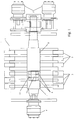
- the single figure of the accompanying drawing shows a rotor 1 of a crusher or crusher, which is provided with grinding hammers 2, eclipsable or fixed and / or cutting tools 3.
- this rotor 1 is mounted in a chamber grinding system which can be provided with screening grids, anvils, counter-tools, impact shields and ejection valves.
- a chamber grinding system which can be provided with screening grids, anvils, counter-tools, impact shields and ejection valves.
- the rotor 1 is constituted in two parts 4 and 5 driven independently of one another.
- one of the parts 4 of the rotor 1 is equipped with fixed cutting tools 3, while the second part 5 of the rotor 1 is equipped with fixed or retractable hammers 2 and the rotor 1 has an inclination of its longitudinal axis relative to the horizontal, the first part 4 of the rotor 1, equipped with fixed cutting tools 3 at the upper end of the rotor 1.
- the upper part of the rotor 1, equipped with fixed cutting tools 3, makes it possible to nibble the products entering the mill, the reduced elements thus obtained being then processed in the second, lower part of the mill by the hammers 2 fixed or retractable of the second part 5 of the rotor 1.
- the rotor 1 comprises a first part 4 driven by one or more first motor 4 'and forming, on the side opposite to its driving by the motor 4', a bearing 41 for receiving an end shaft 51 of the second part 5 of the rotor 1 driven by one or more second motor 5 ', the guide shaft 51 in the housing 41 being provided by means of ball bearings 6 and / or rollers.
- each part 4 and 5 of the rotor 1 can be driven, on the opposite side to its connection by cylindrical guidance to the other part, by its own motor 4 'or 5'.
- one of the parts 4 or 5 of the rotor 1 can be rotated by means of a drive shaft passing through the shaft of driving the other part 5 or 4 of said rotor 1.
- a drive shaft passing through the shaft of driving the other part 5 or 4 of said rotor 1.
- each rotor part 4 'and 5' is driven at a speed different from that of the other part.
- one of the parts 4 of the rotor 1 may advantageously be equipped with fixed cutting tools 3, while the second part 5 of the rotor 1 may be equipped with fixed or retractable hammers 2.
- the part 4 of the rotor 1 can perform, for example, a pre-shredding work, and will be driven by a relatively slow rotation speed, the cutting tools 3 being sensitive to shocks and may cause a blockage of the part 4 of the rotor, which could cause considerable damage at a higher speed.
- this first rotor part 4 can ensure a significant dimensional reduction of the products.
- the second part 5 of the rotor 1 may, in such a case, perform the work of a finishing rotor by grinding the materials to obtain the dimensional reduction and the desired density.
- This second rotor part 5 which is advantageously equipped with eclipsable hammers, will preferably rotate at a higher speed than the first part 4.
- the rotor 1 will have an inclination of its longitudinal axis relative to the horizontal, the first part 4 of the rotor 1, equipped with fixed cutting tools 3 at the upper end of the rotor 1.
- the materials to grind may be brought to the rotor 1, at its first portion 4, to be shredded, the shredded elements then being conveyed by gravity inside the grinding chamber to the second portion 5 of the rotor 1 for the finishing grinding.
- the invention makes it possible to produce a multi-purpose machine performing, in a single work cycle, pre-grinding of the materials which may be of large size, followed by finishing grinding to achieve the desired size reduction and density.
- the machine according to the invention thus makes it possible to perform two separate operations of material processing in a single work cycle, whereas in a conventional material processing installation, it is necessary to implement two separate machines.
- these machines each require a clean feed device and, to ensure continuity of operations, a means of transferring the pre-shredded products to the finishing installation. All these known installations therefore require complex electrical equipment.
Landscapes
- Engineering & Computer Science (AREA)
- Food Science & Technology (AREA)
- Crushing And Pulverization Processes (AREA)
Description
- La présente invention concerne le domaine du traitement de matériaux de toutes origines, en particulier par déchiquetage au moyen de concasseurs ou de broyeurs à marteaux, ou analogues et a pour objet un tel broyeur ou concasseur à marteaux, ou analogues, pourvu d'un rotor en deux parties.
- La récupération de produits métalliques à partir d'objets hors d'usage, en particulier de véhicules automobiles, au moyen de concasseurs ou de broyeurs, s'effectue généralement par introduction des objets dans un broyeur à marteaux, par l'intermédiaire d'une rampe d'introduction équipée d'un tambour écraseur ; ledit broyeur à marteaux arrache et déchiquette la matière y entrant, par interaction avec une ou plusieurs enclumes, qui éjecte et/ou évacue à travers des parois criblantes les déchets mécaniques obtenus présentant un calibre déterminé. Ces déchets sont ensuite traités en vue d'une élimination des matières impropres à la réutilisation et d'un tri des matières restantes en fonction de leurs caractéristiques métallurgiques.
- Les broyeurs à marteaux connus à ce jour, dont les marteaux sont généralement montés sur un rotor constitué par un assemblage de disques et sont éclipsables dans le rotor permettent, généralement, un broyage correct des produits suivant une densité prédéterminée.
- Cependant, dans le cas du traitement de déchets de longueur importante, il se présente, avec ces broyeurs, même s'ils sont de très fortes capacité et puissance, un risque de bourrage dû à l'effet d'entraînement qui leur est propre et au fait que lesdits produits sont monolithiques, comme, par exemple, des barres ou des plaques de grandes dimensions.
- Il est donc nécessaire de réaliser un traitement préalable de tels produits, afin de rendre possible une alimentation plus régulière et sans risque de bourrage des broyeurs. Un tel traitement préalable est généralement effectué dans des installations en aval du site de broyage, les produits étant d'abord prédécoupés et ensuite transportés vers ledit site de broyage.
- Il en résulte la mise en oeuvre de moyens complexes et onéreux, ainsi qu'un encombrement important de l'installation, pouvant être incompatible avec un traitement décentralisé de plus faible volume.
- Un broyeur selon le préambule de la revendication 1 est connu du document
FR-A-2 242 150 - La présente invention a pour but de proposer un broyeur selon le préambule de la revendication 1 permettant de réaliser le traitement complet de produits à broyer en une seule opération, avec une machine unique, dans un encombrement réduit et à moindre frais.
- Ce but est atteint grâce aux caractéristiques de la partie caractérisante de la revendication 1.
- L'invention sera mieux comprise, grâce à la description ci-après, qui se rapporte à un mode de réalisation préféré, donné à titre d'exemple non limitatif et expliqué avec référence au dessin schématique annexé, dont la figure unique est une vue en élévation latérale et en coupe d'un broyeur ou concasseur conforme à l'invention.
- La figure unique du dessin annexé représente un rotor 1 d'un broyeur ou concasseur, qui est muni de marteaux de broyage 2, éclipsables ou fixes et/ou d'outils coupants 3. De manière connue, ce rotor 1 est monté dans une enceinte de broyage pouvant être pourvue de grilles criblantes, d'enclumes, de contre-outils, d'écrans de chocs et de clapets d'éjection. Pour une représentation plus claire de l'invention, seul le rotor 1, qui est monté dans l'enceinte de broyage, est représenté au dessin annexé.
- Conformément à l'invention, le rotor 1 est constitué en deux parties 4 et 5 entraînées indépendamment l'une de l'autre.
- A cet effet, l'une des parties 4 du rotor 1 est équipée d'outils coupants fixes 3, alors que la deuxième partie 5 du rotor 1 est équipée de marteaux 2 fixes ou éclipsables et le rotor 1 présente une inclinaison de son axe longitudinal par rapport à l'horizontale, la première partie 4 du rotor 1, équipée d'outils coupants 3 fixes se présentant à l'extrémité supérieure du rotor 1.
- Il est également possible, suivant une variante de réalisation de l'invention, de mettre en oeuvre un rotor vertical à alimentation par le haut ou latéralement, la première partie 4 du rotor 1, équipée d'outils coupants 3 fixes se présentant à l'extrémité supérieure du rotor 1.
- Ainsi, la partie supérieure du rotor 1, équipée d'outils coupants 3 fixes, permet de réaliser un grignotage des produits entrant dans le broyeur, les éléments réduits ainsi obtenus étant ensuite traités dans la deuxième partie, inférieure, du broyeur par les marteaux 2 fixes ou éclipsables de la deuxième partie 5 du rotor 1.
- Le rotor 1 comporte une première partie 4 entraînée par un ou plusieurs premier moteur 4' et formant, du côté opposé à son entraînement par le moteur 4' un palier 41 de logement d'un arbre d'extrémité 51 de la deuxième partie 5 du rotor 1 entraînée par un ou plusieurs deuxième moteur 5', le guidage de l'arbre 51 dans le logement 41 étant assuré par l'intermédiaire de roulements 6 à billes et/ou à rouleaux. Ainsi, chaque partie 4 et 5 du rotor 1 peut être entraînée, du côté opposé à sa liaison par guidage cylindrique à l'autre partie, par son propre moteur 4' ou 5'.
- Conformément à une variante de réalisation de l'invention, non représenté au dessin annexé, l'une des parties 4 ou 5 du rotor 1 peut être entraînée en rotation par l'intermédiaire d'un arbre d'entraînement traversant l'arbre d'entraînement de l'autre partie 5 ou 4 dudit rotor 1. Ainsi, il est possible d'effectuer l'entraînement des deux parties d'un même côté du rotor.
- Selon une autre caractéristique de l'invention, chaque partie de rotor 4' et 5' est entraînée à une vitesse différente de celle de l'autre partie.
- Par ailleurs, l'une des parties 4 du rotor 1 peut avantageusement être équipée d'outils coupants fixes 3, alors que la deuxième partie 5 du rotor 1 peut être équipée de marteaux 2 fixes ou éclipsables.
- Ainsi, la partie 4 du rotor 1 pourra réaliser, par exemple, un travail de pré-déchiquetage, et sera animée d'une vitesse de rotation relativement lente, les outils coupants 3 étant sensibles aux chocs et risquant d'entraîner un blocage de la partie 4 du rotor, ce qui pourrait engendrer des dégâts considérables à une vitesse plus élevée. Par contre, cette première partie de rotor 4 peut assurer une réduction dimensionnelle importante des produits.
- La deuxième partie 5 du rotor 1 pourra, dans un tel cas, effectuer le travail d'un rotor de finition en effectuant un broyage des matériaux permettant l'obtention de la réduction dimensionnelle et de la densité souhaitée.
- Cette deuxième partie de rotor 5, qui est avantageusement équipée de marteaux éclipsables tournera préférentiellement à une vitesse plus élevée que la première partie 4.
- De préférence, le rotor 1 présentera une inclinaison de son axe longitudinal par rapport à l'horizontale, la première partie 4 du rotor 1, équipée d'outils coupants 3 fixes se présentant à l'extrémité supérieure du rotor 1. Ainsi, les matériaux à broyer pourront être amenés au rotor 1, au niveau de sa première partie 4, pour y être déchiquetés, les éléments déchiquetés étant ensuite acheminés par gravité à l'intérieur de l'enceinte de broyage à la deuxième partie 5 du rotor 1 pour le broyage de finition.
- Il est également possible de mettre en oeuvre un rotor vertical à alimentation par le haut ou latéralement. Dans un tel cas, on aboutit au même effet que dans le cas d'un rotor à axe longitudinal incliné par rapport à l'horizontale.
- L'invention permet de réaliser une machine polyvalente effectuant, en un seul cycle de travail un pré-broyage des matériaux qui peuvent être de grande dimension, suivi d'un broyage de finition pour aboutir à la réduction de taille et à la densité souhaitées. La machine conforme à l'invention permet donc d'effectuer deux opérations distinctes de traitement de matériaux en un seul cycle de travail, alors que dans une installation classique de traitement de matériaux, il est nécessaire de mettre en oeuvre deux machines distinctes. Or, ces machines nécessitent chacune un dispositif d'alimentation propre et, pour garantir la continuité des opérations, un moyen de transfert des produits pré-déchiquetés vers l'installation de finition. Tout ces installations connues nécessitent donc un équipement électrique complexe.
- Grâce à l'invention, il est possible de réaliser une machine polyvalente unique remplaçant une installation complexe de pré-déchiquetage et de broyage, de sorte qu'un chantier de récupération de ferrailles par broyage de matériaux peut être simplifié de manière importante et donc être réalisé à un coût nettement moins élevé. En outre, une telle installation peut aisément être rendue mobile.
- Bien entendu, l'invention n'est pas limitée au mode de réalisation décrit et représenté au dessin annexé. Des modifications restent possibles, notamment du point de vue de la constitution des divers éléments ou par substitution d'équivalents techniques, sans sortir pour autant du domaine de protection de l'invention.
Claims (5)
- Broyeur essentiellement constitué par un rotor (1) muni de marteaux (2) et d'outils coupants (3), monté dans une enceinte de broyage pouvant être pourvue de grilles criblantes, d'enclumes, de contre-outils, d'écrans de chocs et de clapets d'éjection, le rotor (1) étant constitué de deux parties (4 et 5) entraînées indépendamment l'une de l'autre, l'une des parties (4) du rotor (1) étant équipée d'outils coupants fixes (3), et l'autre partie (5) du rotor (1) étant équipée de marteaux (2) fixes ou éclipsables,
broyeur caractérisé en ce que le rotor (1) présente une inclinaison de son axe longitudinal par rapport à l'horizontale ou consiste en un rotor vertical à alimentation par le haut ou latéralement, et en ce que la première partie (4) du rotor (1), équipée d'outils coupants fixes (3) se présente à l'extrémité supérieure du rotor (1), de telle manière que les matériaux à broyer sont amenés au rotor (1), au niveau de sa première partie (4), pour y être déchiquetés, et que les éléments déchiquetés sont ensuite acheminés par gravité à l'intérieur de l'enceinte de broyage à la deuxième partie (5) du rotor (1) pour le broyage de finition. - Broyeur suivant la revendication 1, caractérisé en ce que le rotor (1) comporte une première partie (4) entraînée par un ou plusieurs premier(s) moteur(s) (4') et formant, du côté opposé à son entraînement par le moteur (4') un palier (41) de logement d'un arbre d'extrémité (51) de la deuxième partie (5) du rotor (1) entraînée par un ou plusieurs deuxième moteur (5'), le guidage de l'arbre (51) dans le logement (41) étant assuré par l'intermédiaire de roulements (6) à billes et/ou à rouleaux.
- Broyeur suivant la revendication 1, caractérisé en ce que l'une des parties (4 ou 5) du rotor (1) peut être entraînée en rotation par l'intermédiaire d'un arbre d'entraînement traversant l'arbre d'entraînement de l'autre partie (5 ou 4) dudit rotor (1).
- Broyeur suivant l'une quelconque des revendications 1 à 3, caractérisé en ce que chaque partie de rotor (4' et 5') est entraînée à une vitesse différente de celle de l'autre partie.
- Broyeur suivant l'une quelconque des revendications 1 à 4, caractérisé en ce que la deuxième partie (5) du rotor est animée d'une vitesse plus élevée que la première partie (4) du rotor.
Applications Claiming Priority (2)
| Application Number | Priority Date | Filing Date | Title |
|---|---|---|---|
| FR0955608A FR2949079B1 (fr) | 2009-08-11 | 2009-08-11 | Broyeur ou concasseur a marteaux, ou analogues |
| PCT/FR2010/051690 WO2011018581A1 (fr) | 2009-08-11 | 2010-08-11 | Broyeur ou concasseur a marteaux avec rotor en deux parties |
Publications (2)
| Publication Number | Publication Date |
|---|---|
| EP2464458A1 EP2464458A1 (fr) | 2012-06-20 |
| EP2464458B1 true EP2464458B1 (fr) | 2015-03-11 |
Family
ID=41786389
Family Applications (1)
| Application Number | Title | Priority Date | Filing Date |
|---|---|---|---|
| EP10761037.0A Not-in-force EP2464458B1 (fr) | 2009-08-11 | 2010-08-11 | Broyeur ou concasseur a marteaux avec rotor en 2 parties |
Country Status (4)
| Country | Link |
|---|---|
| EP (1) | EP2464458B1 (fr) |
| ES (1) | ES2538837T3 (fr) |
| FR (1) | FR2949079B1 (fr) |
| WO (1) | WO2011018581A1 (fr) |
Cited By (2)
| Publication number | Priority date | Publication date | Assignee | Title |
|---|---|---|---|---|
| WO2018035982A1 (fr) * | 2016-08-26 | 2018-03-01 | 南通奥普机械工程有限公司 | Système de rotor pour concasseur-sécheur de minerai de nickel latéritique |
| CN111298942A (zh) * | 2020-03-23 | 2020-06-19 | 赵明亮 | 一种药材碾碎装置 |
Families Citing this family (1)
| Publication number | Priority date | Publication date | Assignee | Title |
|---|---|---|---|---|
| CN105562156B (zh) * | 2016-04-01 | 2018-04-27 | 熊以焯 | 复合式转子超微粉碎机 |
Family Cites Families (5)
| Publication number | Priority date | Publication date | Assignee | Title |
|---|---|---|---|---|
| JPS5615946B2 (fr) * | 1973-08-27 | 1981-04-13 | ||
| DE3045009A1 (de) * | 1980-11-28 | 1982-07-01 | Frederico de los Mexico Santos | Verfahren und vorrichtung zur prallzerkleinerung |
| DE3644448C1 (de) * | 1986-12-24 | 1988-06-01 | Kasa Technoplan | Antriebs- und Lageranordnung fuer zwei gegensinnig und nebeneinander umlaufende Rotorsysteme |
| DE29613436U1 (de) * | 1996-08-02 | 1996-09-26 | Patentverwertungs-GmbH Anton Unterwurzacher, Kuchl | Zerkleinerungseinrichtung |
| JP3739303B2 (ja) * | 2001-06-18 | 2006-01-25 | 日機装株式会社 | 粉砕機 |
-
2009
- 2009-08-11 FR FR0955608A patent/FR2949079B1/fr active Active
-
2010
- 2010-08-11 WO PCT/FR2010/051690 patent/WO2011018581A1/fr not_active Ceased
- 2010-08-11 EP EP10761037.0A patent/EP2464458B1/fr not_active Not-in-force
- 2010-08-11 ES ES10761037.0T patent/ES2538837T3/es active Active
Cited By (2)
| Publication number | Priority date | Publication date | Assignee | Title |
|---|---|---|---|---|
| WO2018035982A1 (fr) * | 2016-08-26 | 2018-03-01 | 南通奥普机械工程有限公司 | Système de rotor pour concasseur-sécheur de minerai de nickel latéritique |
| CN111298942A (zh) * | 2020-03-23 | 2020-06-19 | 赵明亮 | 一种药材碾碎装置 |
Also Published As
| Publication number | Publication date |
|---|---|
| WO2011018581A1 (fr) | 2011-02-17 |
| EP2464458A1 (fr) | 2012-06-20 |
| FR2949079B1 (fr) | 2013-02-22 |
| ES2538837T3 (es) | 2015-06-24 |
| FR2949079A1 (fr) | 2011-02-18 |
Similar Documents
| Publication | Publication Date | Title |
|---|---|---|
| EP2560763B1 (fr) | Pre-broyeur ou pre-dechiqueteur avec systeme d'entrainement | |
| WO2012140388A1 (fr) | Installation combinee de traitement de produits par broyage, par dechiquetage ou par compactage | |
| EP2464458B1 (fr) | Broyeur ou concasseur a marteaux avec rotor en 2 parties | |
| EP2470303B1 (fr) | Dispositif compact de cisaillage ou dechiquetage et de broyage de produits a broyer | |
| FR2634400A1 (fr) | Broyeur a marteaux pour le dechiquetage d'objets metalliques muni d'un dispositif de protection du tambour d'entrainement des marteaux | |
| FR2939702A1 (fr) | Procede et dispositif de traitement de produits a broyer | |
| WO2010103241A1 (fr) | Dispositif de compactage et de cisaillage préalable de produits a broyer | |
| CA2648677C (fr) | Porte d'ejection pour broyeur de matiere | |
| CA2746697C (fr) | Broyeur de faible encombrement muni d'un rotor incline par rapport a l'axe de la goulotte d'alimentation | |
| FR2945460A1 (fr) | Dispositif d'entrainement du rotor d'un broyeur, d'un concasseur ou analogue | |
| FR2670133A1 (fr) | Broyeur a marteaux de faible encombrement pour le dechiquetage d'objets metalliques ou autres. | |
| EP2070595B1 (fr) | Dispositif de réduction dimensionnelle par broyage, par concassage, par déchiquetage ou par grignotage, de matériaux ou de produits manufacturés de dimensions importantes | |
| FR2949086A1 (fr) | Dispositif de cisaillage de produits a broyer et installation combinee comprenant un tel dispositif | |
| EP2701847B1 (fr) | Pre-broyeur ou pre-dechiqueteur | |
| FR2691079A1 (fr) | Broyeur compact notamment pour déchets. | |
| FR2963742A1 (fr) | Broyeur ou concasseur a marteaux ou analogue muni d'un dispositif d'extraction du rotor | |
| FR2949082A1 (fr) | Pre-broyeur ou pre-dechiqueteur |
Legal Events
| Date | Code | Title | Description |
|---|---|---|---|
| PUAI | Public reference made under article 153(3) epc to a published international application that has entered the european phase |
Free format text: ORIGINAL CODE: 0009012 |
|
| 17P | Request for examination filed |
Effective date: 20120312 |
|
| AK | Designated contracting states |
Kind code of ref document: A1 Designated state(s): AL AT BE BG CH CY CZ DE DK EE ES FI FR GB GR HR HU IE IS IT LI LT LU LV MC MK MT NL NO PL PT RO SE SI SK SM TR |
|
| DAX | Request for extension of the european patent (deleted) | ||
| GRAP | Despatch of communication of intention to grant a patent |
Free format text: ORIGINAL CODE: EPIDOSNIGR1 |
|
| INTG | Intention to grant announced |
Effective date: 20140924 |
|
| GRAS | Grant fee paid |
Free format text: ORIGINAL CODE: EPIDOSNIGR3 |
|
| GRAA | (expected) grant |
Free format text: ORIGINAL CODE: 0009210 |
|
| AK | Designated contracting states |
Kind code of ref document: B1 Designated state(s): AL AT BE BG CH CY CZ DE DK EE ES FI FR GB GR HR HU IE IS IT LI LT LU LV MC MK MT NL NO PL PT RO SE SI SK SM TR |
|
| REG | Reference to a national code |
Ref country code: GB Ref legal event code: FG4D Free format text: NOT ENGLISH |
|
| REG | Reference to a national code |
Ref country code: CH Ref legal event code: EP |
|
| REG | Reference to a national code |
Ref country code: IE Ref legal event code: FG4D Free format text: LANGUAGE OF EP DOCUMENT: FRENCH |
|
| REG | Reference to a national code |
Ref country code: AT Ref legal event code: REF Ref document number: 715007 Country of ref document: AT Kind code of ref document: T Effective date: 20150415 |
|
| REG | Reference to a national code |
Ref country code: DE Ref legal event code: R096 Ref document number: 602010023064 Country of ref document: DE Effective date: 20150423 |
|
| RAP2 | Party data changed (patent owner data changed or rights of a patent transferred) |
Owner name: LUXERD SA |
|
| RIN2 | Information on inventor provided after grant (corrected) |
Inventor name: BECKER, CAROLINE Inventor name: BECKER, CATHERINE Inventor name: BECKER, ARNAUD |
|
| REG | Reference to a national code |
Ref country code: ES Ref legal event code: FG2A Ref document number: 2538837 Country of ref document: ES Kind code of ref document: T3 Effective date: 20150624 |
|
| REG | Reference to a national code |
Ref country code: NL Ref legal event code: VDEP Effective date: 20150311 |
|
| REG | Reference to a national code |
Ref country code: NL Ref legal event code: VDEP Effective date: 20150311 |
|
| PG25 | Lapsed in a contracting state [announced via postgrant information from national office to epo] |
Ref country code: NO Free format text: LAPSE BECAUSE OF FAILURE TO SUBMIT A TRANSLATION OF THE DESCRIPTION OR TO PAY THE FEE WITHIN THE PRESCRIBED TIME-LIMIT Effective date: 20150611 Ref country code: SE Free format text: LAPSE BECAUSE OF FAILURE TO SUBMIT A TRANSLATION OF THE DESCRIPTION OR TO PAY THE FEE WITHIN THE PRESCRIBED TIME-LIMIT Effective date: 20150311 Ref country code: FI Free format text: LAPSE BECAUSE OF FAILURE TO SUBMIT A TRANSLATION OF THE DESCRIPTION OR TO PAY THE FEE WITHIN THE PRESCRIBED TIME-LIMIT Effective date: 20150311 Ref country code: HR Free format text: LAPSE BECAUSE OF FAILURE TO SUBMIT A TRANSLATION OF THE DESCRIPTION OR TO PAY THE FEE WITHIN THE PRESCRIBED TIME-LIMIT Effective date: 20150311 Ref country code: LT Free format text: LAPSE BECAUSE OF FAILURE TO SUBMIT A TRANSLATION OF THE DESCRIPTION OR TO PAY THE FEE WITHIN THE PRESCRIBED TIME-LIMIT Effective date: 20150311 |
|
| REG | Reference to a national code |
Ref country code: LT Ref legal event code: MG4D |
|
| PG25 | Lapsed in a contracting state [announced via postgrant information from national office to epo] |
Ref country code: GR Free format text: LAPSE BECAUSE OF FAILURE TO SUBMIT A TRANSLATION OF THE DESCRIPTION OR TO PAY THE FEE WITHIN THE PRESCRIBED TIME-LIMIT Effective date: 20150612 Ref country code: LV Free format text: LAPSE BECAUSE OF FAILURE TO SUBMIT A TRANSLATION OF THE DESCRIPTION OR TO PAY THE FEE WITHIN THE PRESCRIBED TIME-LIMIT Effective date: 20150311 |
|
| PG25 | Lapsed in a contracting state [announced via postgrant information from national office to epo] |
Ref country code: NL Free format text: LAPSE BECAUSE OF FAILURE TO SUBMIT A TRANSLATION OF THE DESCRIPTION OR TO PAY THE FEE WITHIN THE PRESCRIBED TIME-LIMIT Effective date: 20150311 |
|
| PG25 | Lapsed in a contracting state [announced via postgrant information from national office to epo] |
Ref country code: CZ Free format text: LAPSE BECAUSE OF FAILURE TO SUBMIT A TRANSLATION OF THE DESCRIPTION OR TO PAY THE FEE WITHIN THE PRESCRIBED TIME-LIMIT Effective date: 20150311 Ref country code: RO Free format text: LAPSE BECAUSE OF FAILURE TO SUBMIT A TRANSLATION OF THE DESCRIPTION OR TO PAY THE FEE WITHIN THE PRESCRIBED TIME-LIMIT Effective date: 20150311 Ref country code: SK Free format text: LAPSE BECAUSE OF FAILURE TO SUBMIT A TRANSLATION OF THE DESCRIPTION OR TO PAY THE FEE WITHIN THE PRESCRIBED TIME-LIMIT Effective date: 20150311 Ref country code: EE Free format text: LAPSE BECAUSE OF FAILURE TO SUBMIT A TRANSLATION OF THE DESCRIPTION OR TO PAY THE FEE WITHIN THE PRESCRIBED TIME-LIMIT Effective date: 20150311 Ref country code: PT Free format text: LAPSE BECAUSE OF FAILURE TO SUBMIT A TRANSLATION OF THE DESCRIPTION OR TO PAY THE FEE WITHIN THE PRESCRIBED TIME-LIMIT Effective date: 20150713 |
|
| PG25 | Lapsed in a contracting state [announced via postgrant information from national office to epo] |
Ref country code: PL Free format text: LAPSE BECAUSE OF FAILURE TO SUBMIT A TRANSLATION OF THE DESCRIPTION OR TO PAY THE FEE WITHIN THE PRESCRIBED TIME-LIMIT Effective date: 20150311 Ref country code: IS Free format text: LAPSE BECAUSE OF FAILURE TO SUBMIT A TRANSLATION OF THE DESCRIPTION OR TO PAY THE FEE WITHIN THE PRESCRIBED TIME-LIMIT Effective date: 20150711 |
|
| REG | Reference to a national code |
Ref country code: DE Ref legal event code: R097 Ref document number: 602010023064 Country of ref document: DE |
|
| PLBE | No opposition filed within time limit |
Free format text: ORIGINAL CODE: 0009261 |
|
| STAA | Information on the status of an ep patent application or granted ep patent |
Free format text: STATUS: NO OPPOSITION FILED WITHIN TIME LIMIT |
|
| PG25 | Lapsed in a contracting state [announced via postgrant information from national office to epo] |
Ref country code: DK Free format text: LAPSE BECAUSE OF FAILURE TO SUBMIT A TRANSLATION OF THE DESCRIPTION OR TO PAY THE FEE WITHIN THE PRESCRIBED TIME-LIMIT Effective date: 20150311 |
|
| 26N | No opposition filed |
Effective date: 20151214 |
|
| PG25 | Lapsed in a contracting state [announced via postgrant information from national office to epo] |
Ref country code: SI Free format text: LAPSE BECAUSE OF FAILURE TO SUBMIT A TRANSLATION OF THE DESCRIPTION OR TO PAY THE FEE WITHIN THE PRESCRIBED TIME-LIMIT Effective date: 20150311 |
|
| PG25 | Lapsed in a contracting state [announced via postgrant information from national office to epo] |
Ref country code: MC Free format text: LAPSE BECAUSE OF FAILURE TO SUBMIT A TRANSLATION OF THE DESCRIPTION OR TO PAY THE FEE WITHIN THE PRESCRIBED TIME-LIMIT Effective date: 20150311 Ref country code: LU Free format text: LAPSE BECAUSE OF FAILURE TO SUBMIT A TRANSLATION OF THE DESCRIPTION OR TO PAY THE FEE WITHIN THE PRESCRIBED TIME-LIMIT Effective date: 20150811 |
|
| REG | Reference to a national code |
Ref country code: CH Ref legal event code: PL |
|
| GBPC | Gb: european patent ceased through non-payment of renewal fee |
Effective date: 20150811 |
|
| PG25 | Lapsed in a contracting state [announced via postgrant information from national office to epo] |
Ref country code: CH Free format text: LAPSE BECAUSE OF NON-PAYMENT OF DUE FEES Effective date: 20150831 Ref country code: LI Free format text: LAPSE BECAUSE OF NON-PAYMENT OF DUE FEES Effective date: 20150831 |
|
| REG | Reference to a national code |
Ref country code: IE Ref legal event code: MM4A |
|
| PG25 | Lapsed in a contracting state [announced via postgrant information from national office to epo] |
Ref country code: GB Free format text: LAPSE BECAUSE OF NON-PAYMENT OF DUE FEES Effective date: 20150811 Ref country code: IE Free format text: LAPSE BECAUSE OF NON-PAYMENT OF DUE FEES Effective date: 20150811 |
|
| REG | Reference to a national code |
Ref country code: FR Ref legal event code: PLFP Year of fee payment: 7 |
|
| REG | Reference to a national code |
Ref country code: AT Ref legal event code: UEP Ref document number: 715007 Country of ref document: AT Kind code of ref document: T Effective date: 20150311 |
|
| PG25 | Lapsed in a contracting state [announced via postgrant information from national office to epo] |
Ref country code: MT Free format text: LAPSE BECAUSE OF FAILURE TO SUBMIT A TRANSLATION OF THE DESCRIPTION OR TO PAY THE FEE WITHIN THE PRESCRIBED TIME-LIMIT Effective date: 20150311 |
|
| PG25 | Lapsed in a contracting state [announced via postgrant information from national office to epo] |
Ref country code: SM Free format text: LAPSE BECAUSE OF FAILURE TO SUBMIT A TRANSLATION OF THE DESCRIPTION OR TO PAY THE FEE WITHIN THE PRESCRIBED TIME-LIMIT Effective date: 20150311 Ref country code: BG Free format text: LAPSE BECAUSE OF FAILURE TO SUBMIT A TRANSLATION OF THE DESCRIPTION OR TO PAY THE FEE WITHIN THE PRESCRIBED TIME-LIMIT Effective date: 20150311 Ref country code: HU Free format text: LAPSE BECAUSE OF FAILURE TO SUBMIT A TRANSLATION OF THE DESCRIPTION OR TO PAY THE FEE WITHIN THE PRESCRIBED TIME-LIMIT; INVALID AB INITIO Effective date: 20100811 |
|
| PG25 | Lapsed in a contracting state [announced via postgrant information from national office to epo] |
Ref country code: CY Free format text: LAPSE BECAUSE OF FAILURE TO SUBMIT A TRANSLATION OF THE DESCRIPTION OR TO PAY THE FEE WITHIN THE PRESCRIBED TIME-LIMIT Effective date: 20150311 |
|
| PG25 | Lapsed in a contracting state [announced via postgrant information from national office to epo] |
Ref country code: TR Free format text: LAPSE BECAUSE OF FAILURE TO SUBMIT A TRANSLATION OF THE DESCRIPTION OR TO PAY THE FEE WITHIN THE PRESCRIBED TIME-LIMIT Effective date: 20150311 |
|
| REG | Reference to a national code |
Ref country code: FR Ref legal event code: PLFP Year of fee payment: 8 |
|
| PGFP | Annual fee paid to national office [announced via postgrant information from national office to epo] |
Ref country code: FR Payment date: 20170831 Year of fee payment: 8 |
|
| PGFP | Annual fee paid to national office [announced via postgrant information from national office to epo] |
Ref country code: AT Payment date: 20170831 Year of fee payment: 8 |
|
| PGFP | Annual fee paid to national office [announced via postgrant information from national office to epo] |
Ref country code: DE Payment date: 20171128 Year of fee payment: 8 |
|
| PGFP | Annual fee paid to national office [announced via postgrant information from national office to epo] |
Ref country code: ES Payment date: 20171129 Year of fee payment: 8 Ref country code: BE Payment date: 20171130 Year of fee payment: 8 Ref country code: IT Payment date: 20171127 Year of fee payment: 8 |
|
| PG25 | Lapsed in a contracting state [announced via postgrant information from national office to epo] |
Ref country code: MK Free format text: LAPSE BECAUSE OF FAILURE TO SUBMIT A TRANSLATION OF THE DESCRIPTION OR TO PAY THE FEE WITHIN THE PRESCRIBED TIME-LIMIT Effective date: 20150311 |
|
| PG25 | Lapsed in a contracting state [announced via postgrant information from national office to epo] |
Ref country code: AL Free format text: LAPSE BECAUSE OF FAILURE TO SUBMIT A TRANSLATION OF THE DESCRIPTION OR TO PAY THE FEE WITHIN THE PRESCRIBED TIME-LIMIT Effective date: 20150311 |
|
| REG | Reference to a national code |
Ref country code: DE Ref legal event code: R119 Ref document number: 602010023064 Country of ref document: DE |
|
| REG | Reference to a national code |
Ref country code: AT Ref legal event code: MM01 Ref document number: 715007 Country of ref document: AT Kind code of ref document: T Effective date: 20180811 |
|
| PG25 | Lapsed in a contracting state [announced via postgrant information from national office to epo] |
Ref country code: AT Free format text: LAPSE BECAUSE OF NON-PAYMENT OF DUE FEES Effective date: 20180811 |
|
| REG | Reference to a national code |
Ref country code: BE Ref legal event code: MM Effective date: 20180831 Ref country code: BE Ref legal event code: PD Owner name: LUXERD SA; LU Free format text: DETAILS ASSIGNMENT: CHANGE OF OWNER(S), AUTRE, TRANSFERT OEB; FORMER OWNER NAME: BECKER, CATHERINE Effective date: 20150618 |
|
| PG25 | Lapsed in a contracting state [announced via postgrant information from national office to epo] |
Ref country code: DE Free format text: LAPSE BECAUSE OF NON-PAYMENT OF DUE FEES Effective date: 20190301 Ref country code: IT Free format text: LAPSE BECAUSE OF NON-PAYMENT OF DUE FEES Effective date: 20180811 |
|
| PG25 | Lapsed in a contracting state [announced via postgrant information from national office to epo] |
Ref country code: FR Free format text: LAPSE BECAUSE OF NON-PAYMENT OF DUE FEES Effective date: 20180831 Ref country code: BE Free format text: LAPSE BECAUSE OF NON-PAYMENT OF DUE FEES Effective date: 20180831 |
|
| REG | Reference to a national code |
Ref country code: ES Ref legal event code: FD2A Effective date: 20190918 |
|
| PG25 | Lapsed in a contracting state [announced via postgrant information from national office to epo] |
Ref country code: ES Free format text: LAPSE BECAUSE OF NON-PAYMENT OF DUE FEES Effective date: 20180812 |