EP2464208B1 - Mähdrescher - Google Patents
Mähdrescher Download PDFInfo
- Publication number
- EP2464208B1 EP2464208B1 EP10733011.0A EP10733011A EP2464208B1 EP 2464208 B1 EP2464208 B1 EP 2464208B1 EP 10733011 A EP10733011 A EP 10733011A EP 2464208 B1 EP2464208 B1 EP 2464208B1
- Authority
- EP
- European Patent Office
- Prior art keywords
- air
- fan
- combine harvester
- cleaning apparatus
- harvester according
- Prior art date
- Legal status (The legal status is an assumption and is not a legal conclusion. Google has not performed a legal analysis and makes no representation as to the accuracy of the status listed.)
- Not-in-force
Links
- 238000004140 cleaning Methods 0.000 claims description 40
- 238000011144 upstream manufacturing Methods 0.000 claims description 5
- 235000013339 cereals Nutrition 0.000 description 30
- 239000010902 straw Substances 0.000 description 13
- 230000000694 effects Effects 0.000 description 9
- 241001272996 Polyphylla fullo Species 0.000 description 4
- 241001124569 Lycaenidae Species 0.000 description 3
- 239000000463 material Substances 0.000 description 3
- 230000004048 modification Effects 0.000 description 3
- 238000012986 modification Methods 0.000 description 3
- 238000000926 separation method Methods 0.000 description 3
- 239000010908 plant waste Substances 0.000 description 2
- 240000002791 Brassica napus Species 0.000 description 1
- 235000006008 Brassica napus var napus Nutrition 0.000 description 1
- 241000196324 Embryophyta Species 0.000 description 1
- 240000008042 Zea mays Species 0.000 description 1
- 235000016383 Zea mays subsp huehuetenangensis Nutrition 0.000 description 1
- 235000002017 Zea mays subsp mays Nutrition 0.000 description 1
- 238000007664 blowing Methods 0.000 description 1
- 230000001627 detrimental effect Effects 0.000 description 1
- 238000011161 development Methods 0.000 description 1
- 230000018109 developmental process Effects 0.000 description 1
- 230000005484 gravity Effects 0.000 description 1
- 238000003306 harvesting Methods 0.000 description 1
- 230000001788 irregular Effects 0.000 description 1
- 235000009973 maize Nutrition 0.000 description 1
- 230000010355 oscillation Effects 0.000 description 1
Images


Classifications
-
- A—HUMAN NECESSITIES
- A01—AGRICULTURE; FORESTRY; ANIMAL HUSBANDRY; HUNTING; TRAPPING; FISHING
- A01F—PROCESSING OF HARVESTED PRODUCE; HAY OR STRAW PRESSES; DEVICES FOR STORING AGRICULTURAL OR HORTICULTURAL PRODUCE
- A01F12/00—Parts or details of threshing apparatus
- A01F12/44—Grain cleaners; Grain separators
- A01F12/444—Fanning means
Definitions
- the invention relates to combine harvesters and particularly to the grain cleaning section thereof which is downstream of threshing apparatus.
- a combine harvester cuts the crop material, threshes the grain therefrom, separates the grain from the straw, and cleans the grain before storing in an onboard tank. Straw and crop residue is ejected from the rear of the machine.
- a well established means to clean the grain involves dropping the grain on to a reciprocating sieve in combination with directing an air flow across the top surface of the sieve. The grain passes through the sieve whilst the lighter crop residue, or chaff, is carried by the air stream in a generally horizontal direction and expelled.
- the speed of the air flow is controllable so as to allow the operator to expel the chaff without also blowing the grain out of the machine for all crops and operating conditions.
- the air stream was typically generated by a transverse cross-flow fan which extended across the width of the machine and comprised a plurality of impellor blades supported for rotation around a rotation axis within a generally cylindrical fan housing which included an air intake at each axial end. Therefore, air is drawn in from the surrounding environment in an axial direction from each end and propelled radially by the impellor blades into the housing of the cleaning apparatus so as to provide an air flow through the sieve or sieves. Due to the finite width of this transverse fan arrangement the velocity profile of the expelled air stream is non-uniform in the transverse direction wherein the air stream velocity towards the outside edges of the fan is far greater than that experienced towards the centre. Such a non-uniform air stream profile across the sieves is detrimental to the operation of the machine because a constant air speed across the width of the sieve cannot be set thus requiring the operator to make a trade-off between efficient separation and grain loss.
- the single transverse fan combine manufacturers have divided the single fan into a plurality of axially aligned fan modules which share a common rotation axis.
- Each fan module is axially spaced with an interruption in the fan housing between each module.
- Each gap between the fan modules provides an air intake to allow air to enter each end of all fan modules.
- the provision of intermediate air intakes reduces the distance between the axial centre of each fan module and the air intakes thereby increasing the uniformity of the air stream velocity profile.
- each fan module delivers a sub-stream of air into the cleaning apparatus.
- the spacing between adjacent fan modules results in a dead zone immediately downstream and aligned with the spacing between the modules.
- a combine harvester comprising fan apparatus for generating an air stream through cleaning apparatus for separating chaff from grain, the fan apparatus comprising a plurality of fan modules for generating mutually spaced air sub-streams, wherein the cleaning apparatus comprises an auxiliary air intake located between two adjacent air sub-streams, and means to narrow the passage for each air sub-stream adjacent the auxiliary air intake so as to create a region of lower pressure which draws air directly from the environment into the air stream through the auxiliary air intake.
- the inventors have surprisingly found that the introduction of a direct source of air proximate to the dead zone in combination with means to narrow the passage for each air sub stream, significantly improves the transverse uniformity of the air stream velocity profile.
- the venturi effect is exploited to suck in air directly from the environment, i.e. not passing through the fan apparatus, thus reducing the transverse component of the air stream from each sub stream, in effect producing a more collimated overall air stream.
- this increases the transverse uniformity of the air stream velocity profile further downstream.
- the improvement advantageously allows the operator to employ a higher fan speed without the risk of grain loss in the peak velocity regions. Also, an increased fan speed allows an increased crop flow thus any improved separating apparatus further upstream can be exploited to maximum effect.
- Each fan module may comprise a plurality of impellors supported for rotation around a rotation axis within a generally cylindrical fan housing which includes an air intake at each axial end.
- the rotation axes are preferably axially aligned with respect to one another in a position upstream of the cleaning apparatus.
- the rotation axes are substantially aligned transversely across the width of the harvester so that the air stream, when radially expelled, continues in a generally longitudinal direction through the cleaning apparatus with respect to the normal direction of travel of the harvester.
- adjacent fan houses are axially spaced to allow the intake of air into both axial ends of each fan module.
- Each fan module typically sucks air in from the environment in a generally axial direction and expels the air into the cleaning apparatus in a generally radial direction.
- the cleaning apparatus preferably comprises a vibrating sieve which is substantially horizontal and serves to separate the chaff from the grain, both of which are dropped, in a crop flow, towards the sieve, and wherein the air stream passes over the sieve to blow the chaff rearwardly before reaching the sieve.
- the auxiliary air intake preferably comprises an orifice formed in the base of the cleaning apparatus.
- the cleaning apparatus may further comprise a pair of vertical plates between the adjacent sub-streams and which converge rearwardly, the plates located either side of the orifice and each including a respective vent to allow air to pass from the orifice into the respective sub-streams.
- the means to narrow the passage for each air sub-stream comprise venturi baffle plates which are substantially vertical and reduce the transverse width of each sub-stream in the rearward direction.
- the baffle plates provide a simple mechanism to narrow the passage for the respective sub-streams thereby producing the desired region of lower pressure due to the venturi effect. It is envisaged that alternative means may be employed to narrow the sub-stream passage so as to exploit the venturi effect.
- the combine harvester comprises two or three fan modules and an auxiliary air intake between adjacent pairs of fan modules, each air intake having associated therewith a respective set of venturi baffle plates.
- the provision of three axially aligned fan modules results in two dead regions which have an associated auxiliary air intake in accordance with the invention. It is envisaged also that the fan apparatus may comprise four or even more fan modules.
- the cleaning apparatus may further comprise at least one transverse deflector plate downstream of the fan apparatus to vertically direct the air stream expelled thereby.
- at least one transverse deflector plate downstream of the fan apparatus to vertically direct the air stream expelled thereby.
- this allows the operator to fine tune the profile of the expelled air steam and particularly the height at which the air stream is directed within the cleaning apparatus.
- longitudinal and transverse are made in relation to the combine harvester's normal direction of travel.
- longitudinal equates to the fore and aft direction
- transverse equates to the crosswise direction, or left and right.
- axial and radial are made in relation to a rotating body such as a shaft wherein axial equates to a direction along the rotation axis and radial equates to a direction perpendicular to the rotation axis.
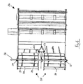
- a combine harvester 10 comprises a header (not shown) which cuts a crop as the harvester 10 is driven across a field.
- the crop is conveyed by an elevator (also not shown) in to a threshing drum, referenced generally at 12.
- the threshing drum 12 rotates on a transverse axis 13 within drum housing 14.
- Threshing bars 15 thresh the grain from the head of each plant and a portion of the grain falls on to a reciprocating grain pan 16.
- the remaining grain and bulk crop material is conveyed rearwardly by transverse transfer cylinders 17,18 into separating apparatus referenced generally at 19.
- the separating apparatus shown comprise five sets of straw walkers 20, each set comprising typically six straw walker elements which are disposed side-by-side across the width of the combine 10.
- the inclined straw walkers 20 oscillate so as to convey the crop material rearwardly wherein the motion causes the grain to fall through holes in the base of each straw walker 20.
- the straw is expelled from the combine harvester 10 through the machine as indicated by arrow 22.
- the grain which falls through the straw walkers 20 is collected by inclined grain pan 23 which moves the grain through gravity in a forward direction and onto grain pan 16.
- the separating apparatus 19 shown comprises a series of straw walkers 20, the invention is equally applicable to a combine harvester having separator apparatus based on the axial flow separation principle wherein an axial rotor, or rotors, is employed to separate the grain from the straw.
- the collected grain is conveyed rearwardly by the oscillation motion of the grain pan 16 into a cleaning shoe referenced generally at 24.
- the grain cascades from the rear of pan 16 onto the surface of a first upper sieve 25.
- Fan apparatus, referenced generally at 26 produces an air stream which passes through upper sieve 25 to propel straw and chaff from the rear of the machine as referenced by arrow 27.
- the grain falls through upper sieve 25 on to a lower, finer, sieve 28.
- the fan apparatus 26 delivers an air stream through lower sieve 28 to carry chaff and straw residue rearwardly.
- the grain which falls through lower sieve 28 is collected on grain pan 29 and conveyed to the grain tanks 30 via an auger 31 and elevator 32.
- the chaff and straw residue which falls from the rear of lower sieve 28 is conveyed forwardly to an auger 33 and onto re-threshing mechanism (not shown) before being passed back into the crop stream to be re-cleaned.
- the invention relates to the fan apparatus 26 and particularly to the generation of the air stream which passes through the lower sieve 28 and upper sieve 25.
- the fan apparatus 26 comprises a pair of fan modules 35 which are arranged side-by-side and share a common transverse shaft 36.
- the transverse fan shaft 36 is supported by bearings 37 which are fixed to the frame of the combine.
- Each fan module 35 includes a set of impellor blades which are supported on the fan shaft 36 by a respective pair of spokes 39.
- the circumferential surface of the generally cylindrical swept envelope of the impellor blades 38 is covered by fan housing 40 which extends across the width of the machine.
- the fan housing 40 is open on its rear side to allow the air stream generated by the impellor blades 38 to pass into housing 42 of the cleaning shoe 24.
- the underside of the fan housing 40 is discontinuous in the region between the two fan modules 35 thereby providing an intermediate air inlet 44.
- the fan shaft 36 is driven by means of a belt and pulley system (not shown) which causes air to be drawn in at each end of the fan housing 40 and through the intermediate gap 44.
- Each fan module 35 propels a respective sub-stream radially and rearwardly into the cleaning shoe 24.
- a pair of vertical plates 46 are fixed to the base 48 of the cleaning shoe 24 immediately downstream of the fan housing 40 and converge in a rearward direction so as to be secured to one another.
- the vertical plates 46 serve to define the boundaries of the passage way for each sub-stream.
- a central vertical vane 49 is secured to the convergent point of the vertical plates 46 and serves to maintain separation between the two sub-streams.
- a triangular hole 50 is formed in the base of the cleaning shoe 48 immediately behind the fan apparatus 26 and between the vertical plates 46.
- Vertical baffle plates 52 are positioned immediately downstream of each fan module 35 and serve to narrow the passage for each sub-stream in the transverse direction at the edge adjacent the intermediate gap 44. As is shown in Figure 5 , the narrowing of the passage creates a higher velocity region H caused by the venturi effect wherein the sub-stream is forced around the baffle plates 52. The high velocity region H lowers the pressure in the vicinity and creates a low pressure region L. The low pressure region L serves to draw in air through auxiliary orifice 50 directly from the environment as referenced by arrows 55. This effect is mirrored on both left and right sides in the region between the two fan modules 35.
- auxiliary air intake 50 and baffle plates 52 exploits the venturi effect to deliver a more uniform air stream velocity profile across the width and depth of the cleaning shoe 24.
- the introduction of a direct air source in between the two sub-streams generated by the respective fan modules 35 serves to reduce any transverse component of the sub-stream direction in which, without the auxiliary air source, the two sub-streams would merge deep within the cleaning shoe 24 thereby creating undesirable peaks and troughs.
- the collimated air flow through the cleaning shoe 24 allows an operator greater flexibility in operating at higher fan speeds thereby improving the throughput of the cleaning shoe 24 and thus the overall combine.
Landscapes
- Life Sciences & Earth Sciences (AREA)
- Environmental Sciences (AREA)
- Threshing Machine Elements (AREA)
- Structures Of Non-Positive Displacement Pumps (AREA)
Claims (12)
- Mähdrescher mit einer Ventilator-Einrichtung zur Erzeugung eines Luftstroms durch eine Reinigungs-Einrichtung zum Trennen von Spreu von Körnern, wobei die Ventilator-Einrichtung mehrere Ventilator-Module besitzt zur Erzeugung voneinander beabstandeter Luft-Teilströme, welche sich stromabwärts in der Reinigungs-Einrichtung vereinigen, und wobei die Reinigungs-Einrichtung einen Hilfs-Lufteinlass aufweist, der zwischen zwei benachbarten Luft-Teilströmen angeordnet ist, und mit einem Organ zur Verengung des Durchtritts für jeden Luft-Teilstrom benachbart dem Hilfs-Lufteinlass zur Schaffung eines Bereichs mit geringerem Druck, der Luft durch den Hilfs-Lufteinlass direkt aus der Umgebung in den Luftstrom saugt.
- Mähdrescher nach Anspruch 1, wobei jedes Ventilator-Modul mehrere Lüfterräder aufweist, die geeignet für eine Rotation um eine Rotationsachse in einem grundsätzlich zylindrischen Ventilator-Gehäuse, welches an jedem axialen Ende einen Lufteinlass aufweist, abgestützt sind.
- Mähdrescher nach Anspruch 2, wobei die jeweiligen Rotationsachsen stromaufwärts der Reinigungs-Einrichtung im Wesentlichen axial zueinander ausgerichtet sind.
- Mähdrescher nach Anspruch 2 oder 3, wobei die Rotationsachsen im Wesentlichen transversal über die Breite des Mähdreschers angeordnet oder zueinander fluchten, wobei der Luftstrom durch die Reinigungs-Einrichtung grundsätzlich in Längsrichtung verläuft.
- Mähdrescher nach Anspruch 2, 3 oder 4, wobei jedes Ventilator-Gehäuse axial beabstandet ist, um einen Einlass von Luft in beide axialen Enden jedes Ventilator-Moduls zu ermöglichen.
- Mähdrescher nach einem der Ansprüche 2 bis 5, wobei jedes Ventilator-Modul aus der Umgebung Luft in eine im Wesentlichen axiale Richtung einsaugt und Luft in eine grundsätzlich radiale Richtung in die Reinigungs-Einrichtung herausfördert.
- Mähdrescher nach einem der vorhergehenden Ansprüche, wobei die Reinigungs-Einrichtung ein Vibrations-Sieb aufweist, welches im Wesentlichen horizontal angeordnet ist und dem Trennen des Spreus von Körnern dient, wobei Spreu und Körner in einem Erntegut-Fluss in Richtung des Siebs fallen und wobei der Luftstrom über das Sieb strömt zum Blasen des Spreus nach hinten oder rückwärts vor Erreichen des Siebs.
- Mähdrescher nach einem der vorhergehenden Ansprüche, wobei der Hilfs-Lufteinlass eine Öffnung, Blende oder Düse aufweist, die in der Basis der Reinigungseinrichtung gebildet ist.
- Mähdrescher nach Anspruch 8, wobei die Reinigungs-Einrichtung zwischen den beabstandeten Luft-Teilströmen ein Paar vertikaler Platten aufweist, welche nach hinten konvergieren, wobei die Platten auf beiden Seiten der Öffnung, Blende oder Düse angeordnet sind und jeweils eine zugeordnete Entlüftung aufweisen, um ein Strömen von Luft von der Öffnung, Blende oder Düse in die jeweiligen Luft-Teilströme zu ermöglichen.
- Mähdrescher nach einem der vorhergehenden Ansprüche, wobei das Organ zur Verengung des Durchtritts jedes Luft-Teilstroms Ablenkplatten aufweist, welche im Wesentlichen vertikal orientiert sind und nach hinten die transversale Breite jedes Luft-Teilstroms reduzieren.
- Mähdrescher nach einem der vorhergehenden Ansprüche mit drei Ventilator-Modulen und einem Hilfs-Lufteinlass zwischen benachbarten Paaren von Ventilator-Modulen, wobei jedem Lufteinlass ein Satz von Venturi-Ablenkplatten zugeordnet ist.
- Mähdrescher nach einem der vorhergehenden Ansprüche, wobei die Reinigungs-Einrichtung stromabwärts der Ventilator-Einrichtung zumindest eine transversale Ablenkplatte aufweist, die dem vertikalen Führen, Leiten oder Umlenken des Luftstroms dient, welcher hiermit herausgestoßen oder gefördert wird.
Priority Applications (1)
| Application Number | Priority Date | Filing Date | Title |
|---|---|---|---|
| PL10733011T PL2464208T3 (pl) | 2009-08-14 | 2010-07-20 | Kombajn zbożowy |
Applications Claiming Priority (2)
| Application Number | Priority Date | Filing Date | Title |
|---|---|---|---|
| GB0914222A GB2472639A (en) | 2009-08-14 | 2009-08-14 | Fans for grain cleaning section of a combine harvester |
| PCT/EP2010/060464 WO2011018308A1 (en) | 2009-08-14 | 2010-07-20 | Combine harvester |
Publications (2)
| Publication Number | Publication Date |
|---|---|
| EP2464208A1 EP2464208A1 (de) | 2012-06-20 |
| EP2464208B1 true EP2464208B1 (de) | 2013-06-05 |
Family
ID=41171387
Family Applications (1)
| Application Number | Title | Priority Date | Filing Date |
|---|---|---|---|
| EP10733011.0A Not-in-force EP2464208B1 (de) | 2009-08-14 | 2010-07-20 | Mähdrescher |
Country Status (7)
| Country | Link |
|---|---|
| EP (1) | EP2464208B1 (de) |
| CN (1) | CN102625652B (de) |
| BR (1) | BR112012003320A2 (de) |
| GB (1) | GB2472639A (de) |
| PL (1) | PL2464208T3 (de) |
| RU (1) | RU2525267C2 (de) |
| WO (1) | WO2011018308A1 (de) |
Families Citing this family (11)
| Publication number | Priority date | Publication date | Assignee | Title |
|---|---|---|---|---|
| US20140357332A1 (en) * | 2011-07-27 | 2014-12-04 | Agco Corporation | Geometry for controlling air velocity in a combine harvester |
| CN103518489B (zh) * | 2013-10-11 | 2016-01-20 | 华中农业大学 | 一种油菜联合收割机的田间落粒收集方法及装置 |
| US9706709B2 (en) * | 2015-09-10 | 2017-07-18 | Deere & Company | Harvester fan speed control based on yield |
| RU171423U1 (ru) * | 2016-12-28 | 2017-05-31 | Федеральное государственное бюджетное образовательное учреждение высшего образования "Башкирский государственный аграрный университет" | Вентилятор системы очистки зерноуборочного комбайна |
| EP3566568B1 (de) * | 2018-05-09 | 2022-08-10 | CNH Industrial Belgium N.V. | Luftleitblech für eine mähdrescherreinigungsanordnung |
| US11272668B2 (en) * | 2018-09-14 | 2022-03-15 | Cnh Industrial America Llc | Adjustable duct for a combine harvester cleaning fan |
| EP3818812B1 (de) * | 2019-11-05 | 2023-09-20 | CNH Industrial Belgium N.V. | LANDWIRTSCHAFTLICHE ERNTEMASCHINE MIT EINEM SCHLÄGER MIT STOßDÄMPFENDEN SCHAUFELN |
| US12507625B2 (en) | 2019-12-27 | 2025-12-30 | Agco Corporation | Combine harvesters having louvers to adjust air flow, and related methods |
| US20220279726A1 (en) * | 2021-03-04 | 2022-09-08 | Cnh Industrial America Llc | Inlet cover for a cross flow fan |
| US12232444B2 (en) * | 2021-08-06 | 2025-02-25 | Deere & Company | Cleaning fan airflow control system |
| CN115846303A (zh) * | 2022-11-16 | 2023-03-28 | 合肥美的洗衣机有限公司 | 清洁装置 |
Family Cites Families (14)
| Publication number | Priority date | Publication date | Assignee | Title |
|---|---|---|---|---|
| BE560887A (de) * | 1956-09-17 | |||
| DE2423917A1 (de) * | 1974-05-16 | 1975-11-27 | Fahr Ag Maschf | Geblaese fuer dreschmaschinen |
| DE2922607A1 (de) * | 1979-06-02 | 1981-01-08 | Claas Ohg | Geblaese fuer die reinigungsvorrichtung von maehdreschern |
| SU1396998A1 (ru) * | 1986-12-29 | 1988-05-23 | Московский институт инженеров сельскохозяйственного производства им.В.П.Горячкина | Многосекционный вентил тор устройства дл очистки зерна |
| US4906219A (en) * | 1988-08-15 | 1990-03-06 | J. I. Case Company | Cleaning system for a combine |
| CN2082960U (zh) * | 1990-01-15 | 1991-08-21 | 中国农业机械化科学研究院 | 立式轴流脱粒,分离和无筛气流清选装置 |
| CN1013240B (zh) * | 1990-01-15 | 1991-07-24 | 中国农业机械化科学研究院 | 立式轴流脱粒部件外风道气流清选装置 |
| RU2017385C1 (ru) * | 1991-05-28 | 1994-08-15 | Акционерное общество "Ростсельмаш" | Центробежный вентилятор очистки молотилки |
| CN1075051A (zh) * | 1992-01-20 | 1993-08-11 | 李爱民 | 割前脱分选送装置 |
| CN2137857Y (zh) * | 1992-05-11 | 1993-07-14 | 洛阳工学院 | 经济型小型联合收割机 |
| RU2072764C1 (ru) * | 1992-06-29 | 1997-02-10 | Акционерное общество "Ростсельмаш" | Вентилятор очистки зерноуборочного комбайна |
| DE19501828C2 (de) * | 1995-01-21 | 1998-09-24 | Claas Ohg | Gebläse für die Reinigungsvorrichtung von Mähdreschern |
| DE10246858A1 (de) * | 2002-10-08 | 2004-05-06 | Claas Selbstfahrende Erntemaschinen Gmbh | Radialgebläse |
| JP2004254613A (ja) * | 2003-02-26 | 2004-09-16 | Iseki & Co Ltd | 脱穀装置 |
-
2009
- 2009-08-14 GB GB0914222A patent/GB2472639A/en not_active Withdrawn
-
2010
- 2010-07-20 BR BR112012003320A patent/BR112012003320A2/pt not_active IP Right Cessation
- 2010-07-20 PL PL10733011T patent/PL2464208T3/pl unknown
- 2010-07-20 WO PCT/EP2010/060464 patent/WO2011018308A1/en not_active Ceased
- 2010-07-20 EP EP10733011.0A patent/EP2464208B1/de not_active Not-in-force
- 2010-07-20 CN CN201080035943.8A patent/CN102625652B/zh not_active Expired - Fee Related
- 2010-07-20 RU RU2012106926/13A patent/RU2525267C2/ru not_active IP Right Cessation
Also Published As
| Publication number | Publication date |
|---|---|
| BR112012003320A2 (pt) | 2016-03-01 |
| PL2464208T3 (pl) | 2013-11-29 |
| WO2011018308A1 (en) | 2011-02-17 |
| CN102625652B (zh) | 2014-10-15 |
| RU2012106926A (ru) | 2013-09-10 |
| GB2472639A (en) | 2011-02-16 |
| EP2464208A1 (de) | 2012-06-20 |
| CN102625652A (zh) | 2012-08-01 |
| RU2525267C2 (ru) | 2014-08-10 |
| GB0914222D0 (en) | 2009-09-30 |
Similar Documents
| Publication | Publication Date | Title |
|---|---|---|
| EP2464208B1 (de) | Mähdrescher | |
| JP4955871B2 (ja) | 回転式脱穀及び分離ユニットを備えたコンバインのための吸引ブロワ | |
| RU2415553C2 (ru) | Зерноуборочный комбайн с всасывающим вентилятором | |
| US4250897A (en) | Axial flow rotary combine harvester with plenum-like separator housing | |
| EP2187061B1 (de) | Querstromlüftereinheit mit einem zusätzlichen Lufteinlass zur Ausfüllung bei Luftstromdefiziten | |
| US6921330B2 (en) | Front chaffer and cleaning fan | |
| US10645879B2 (en) | Crop processing apparatus in a combine harvester | |
| RU2488263C2 (ru) | Система механической подачи недомолота для вторичного обмолота на возвратную доску | |
| EP2925116B1 (de) | Saatgutverarbeitungsvorrichtung in einem mähdrescher | |
| US10321634B2 (en) | Combine harvester grain cleaning system | |
| GB2487193A (en) | Combine harvester grain cleaning apparatus | |
| CN102307462A (zh) | 联合收割机 | |
| US7896731B2 (en) | Combine grain cleaning system including a grain cleaning sieve having a region of increased grain throughput | |
| WO2011053416A1 (en) | Corn mog separator | |
| EP3232767B1 (de) | Erntegutverarbeitungsvorrichtung in einem mähdrescher | |
| RU2490862C2 (ru) | Зерноуборочный комбайн с очистным вентилятором | |
| CN107426968A (zh) | 由多个交叉螺旋输送器供应的农业升运机 | |
| US6780102B2 (en) | Transfer mechanism for feeding harvested crop to a separation unit | |
| US3456786A (en) | Grain separating apparatus | |
| US3494115A (en) | Vibrational grain separating apparatus for agricultural combines | |
| US20250048973A1 (en) | Straw Chopper for a Combine Harvester | |
| US20250098579A1 (en) | Chaff and Straw Spreader for a Combine Harvester | |
| EP3481172B1 (de) | Mähdrescher mit einer vorrichtung zum behandeln des erntegutes | |
| CN107846844A (zh) | 农业收割机的螺旋输送器组件 |
Legal Events
| Date | Code | Title | Description |
|---|---|---|---|
| PUAI | Public reference made under article 153(3) epc to a published international application that has entered the european phase |
Free format text: ORIGINAL CODE: 0009012 |
|
| 17P | Request for examination filed |
Effective date: 20120314 |
|
| AK | Designated contracting states |
Kind code of ref document: A1 Designated state(s): AL AT BE BG CH CY CZ DE DK EE ES FI FR GB GR HR HU IE IS IT LI LT LU LV MC MK MT NL NO PL PT RO SE SI SK SM TR |
|
| DAX | Request for extension of the european patent (deleted) | ||
| GRAP | Despatch of communication of intention to grant a patent |
Free format text: ORIGINAL CODE: EPIDOSNIGR1 |
|
| GRAS | Grant fee paid |
Free format text: ORIGINAL CODE: EPIDOSNIGR3 |
|
| GRAA | (expected) grant |
Free format text: ORIGINAL CODE: 0009210 |
|
| AK | Designated contracting states |
Kind code of ref document: B1 Designated state(s): AL AT BE BG CH CY CZ DE DK EE ES FI FR GB GR HR HU IE IS IT LI LT LU LV MC MK MT NL NO PL PT RO SE SI SK SM TR |
|
| REG | Reference to a national code |
Ref country code: GB Ref legal event code: FG4D |
|
| REG | Reference to a national code |
Ref country code: CH Ref legal event code: EP |
|
| REG | Reference to a national code |
Ref country code: AT Ref legal event code: REF Ref document number: 615084 Country of ref document: AT Kind code of ref document: T Effective date: 20130615 |
|
| REG | Reference to a national code |
Ref country code: IE Ref legal event code: FG4D |
|
| REG | Reference to a national code |
Ref country code: DE Ref legal event code: R096 Ref document number: 602010007653 Country of ref document: DE Effective date: 20130801 |
|
| REG | Reference to a national code |
Ref country code: AT Ref legal event code: MK05 Ref document number: 615084 Country of ref document: AT Kind code of ref document: T Effective date: 20130605 |
|
| PG25 | Lapsed in a contracting state [announced via postgrant information from national office to epo] |
Ref country code: NO Free format text: LAPSE BECAUSE OF FAILURE TO SUBMIT A TRANSLATION OF THE DESCRIPTION OR TO PAY THE FEE WITHIN THE PRESCRIBED TIME-LIMIT Effective date: 20130905 Ref country code: AT Free format text: LAPSE BECAUSE OF FAILURE TO SUBMIT A TRANSLATION OF THE DESCRIPTION OR TO PAY THE FEE WITHIN THE PRESCRIBED TIME-LIMIT Effective date: 20130605 Ref country code: SI Free format text: LAPSE BECAUSE OF FAILURE TO SUBMIT A TRANSLATION OF THE DESCRIPTION OR TO PAY THE FEE WITHIN THE PRESCRIBED TIME-LIMIT Effective date: 20130605 Ref country code: LT Free format text: LAPSE BECAUSE OF FAILURE TO SUBMIT A TRANSLATION OF THE DESCRIPTION OR TO PAY THE FEE WITHIN THE PRESCRIBED TIME-LIMIT Effective date: 20130605 Ref country code: FI Free format text: LAPSE BECAUSE OF FAILURE TO SUBMIT A TRANSLATION OF THE DESCRIPTION OR TO PAY THE FEE WITHIN THE PRESCRIBED TIME-LIMIT Effective date: 20130605 Ref country code: SE Free format text: LAPSE BECAUSE OF FAILURE TO SUBMIT A TRANSLATION OF THE DESCRIPTION OR TO PAY THE FEE WITHIN THE PRESCRIBED TIME-LIMIT Effective date: 20130605 Ref country code: ES Free format text: LAPSE BECAUSE OF FAILURE TO SUBMIT A TRANSLATION OF THE DESCRIPTION OR TO PAY THE FEE WITHIN THE PRESCRIBED TIME-LIMIT Effective date: 20130916 Ref country code: GR Free format text: LAPSE BECAUSE OF FAILURE TO SUBMIT A TRANSLATION OF THE DESCRIPTION OR TO PAY THE FEE WITHIN THE PRESCRIBED TIME-LIMIT Effective date: 20130906 |
|
| REG | Reference to a national code |
Ref country code: NL Ref legal event code: VDEP Effective date: 20130605 |
|
| REG | Reference to a national code |
Ref country code: LT Ref legal event code: MG4D |
|
| PG25 | Lapsed in a contracting state [announced via postgrant information from national office to epo] |
Ref country code: HR Free format text: LAPSE BECAUSE OF FAILURE TO SUBMIT A TRANSLATION OF THE DESCRIPTION OR TO PAY THE FEE WITHIN THE PRESCRIBED TIME-LIMIT Effective date: 20130605 Ref country code: BG Free format text: LAPSE BECAUSE OF FAILURE TO SUBMIT A TRANSLATION OF THE DESCRIPTION OR TO PAY THE FEE WITHIN THE PRESCRIBED TIME-LIMIT Effective date: 20130905 |
|
| REG | Reference to a national code |
Ref country code: PL Ref legal event code: T3 |
|
| PG25 | Lapsed in a contracting state [announced via postgrant information from national office to epo] |
Ref country code: LV Free format text: LAPSE BECAUSE OF FAILURE TO SUBMIT A TRANSLATION OF THE DESCRIPTION OR TO PAY THE FEE WITHIN THE PRESCRIBED TIME-LIMIT Effective date: 20130605 |
|
| PG25 | Lapsed in a contracting state [announced via postgrant information from national office to epo] |
Ref country code: CZ Free format text: LAPSE BECAUSE OF FAILURE TO SUBMIT A TRANSLATION OF THE DESCRIPTION OR TO PAY THE FEE WITHIN THE PRESCRIBED TIME-LIMIT Effective date: 20130605 Ref country code: SK Free format text: LAPSE BECAUSE OF FAILURE TO SUBMIT A TRANSLATION OF THE DESCRIPTION OR TO PAY THE FEE WITHIN THE PRESCRIBED TIME-LIMIT Effective date: 20130605 Ref country code: EE Free format text: LAPSE BECAUSE OF FAILURE TO SUBMIT A TRANSLATION OF THE DESCRIPTION OR TO PAY THE FEE WITHIN THE PRESCRIBED TIME-LIMIT Effective date: 20130605 Ref country code: PT Free format text: LAPSE BECAUSE OF FAILURE TO SUBMIT A TRANSLATION OF THE DESCRIPTION OR TO PAY THE FEE WITHIN THE PRESCRIBED TIME-LIMIT Effective date: 20131007 Ref country code: IS Free format text: LAPSE BECAUSE OF FAILURE TO SUBMIT A TRANSLATION OF THE DESCRIPTION OR TO PAY THE FEE WITHIN THE PRESCRIBED TIME-LIMIT Effective date: 20131005 |
|
| PG25 | Lapsed in a contracting state [announced via postgrant information from national office to epo] |
Ref country code: NL Free format text: LAPSE BECAUSE OF FAILURE TO SUBMIT A TRANSLATION OF THE DESCRIPTION OR TO PAY THE FEE WITHIN THE PRESCRIBED TIME-LIMIT Effective date: 20130605 Ref country code: RO Free format text: LAPSE BECAUSE OF FAILURE TO SUBMIT A TRANSLATION OF THE DESCRIPTION OR TO PAY THE FEE WITHIN THE PRESCRIBED TIME-LIMIT Effective date: 20130605 |
|
| PG25 | Lapsed in a contracting state [announced via postgrant information from national office to epo] |
Ref country code: MC Free format text: LAPSE BECAUSE OF FAILURE TO SUBMIT A TRANSLATION OF THE DESCRIPTION OR TO PAY THE FEE WITHIN THE PRESCRIBED TIME-LIMIT Effective date: 20130605 |
|
| PLBE | No opposition filed within time limit |
Free format text: ORIGINAL CODE: 0009261 |
|
| STAA | Information on the status of an ep patent application or granted ep patent |
Free format text: STATUS: NO OPPOSITION FILED WITHIN TIME LIMIT |
|
| REG | Reference to a national code |
Ref country code: IE Ref legal event code: MM4A |
|
| REG | Reference to a national code |
Ref country code: HU Ref legal event code: AG4A Ref document number: E018790 Country of ref document: HU |
|
| PG25 | Lapsed in a contracting state [announced via postgrant information from national office to epo] |
Ref country code: DK Free format text: LAPSE BECAUSE OF FAILURE TO SUBMIT A TRANSLATION OF THE DESCRIPTION OR TO PAY THE FEE WITHIN THE PRESCRIBED TIME-LIMIT Effective date: 20130605 |
|
| 26N | No opposition filed |
Effective date: 20140306 |
|
| REG | Reference to a national code |
Ref country code: DE Ref legal event code: R097 Ref document number: 602010007653 Country of ref document: DE Effective date: 20140306 |
|
| PG25 | Lapsed in a contracting state [announced via postgrant information from national office to epo] |
Ref country code: IE Free format text: LAPSE BECAUSE OF NON-PAYMENT OF DUE FEES Effective date: 20130720 |
|
| REG | Reference to a national code |
Ref country code: CH Ref legal event code: PL |
|
| PG25 | Lapsed in a contracting state [announced via postgrant information from national office to epo] |
Ref country code: LI Free format text: LAPSE BECAUSE OF NON-PAYMENT OF DUE FEES Effective date: 20140731 Ref country code: CH Free format text: LAPSE BECAUSE OF NON-PAYMENT OF DUE FEES Effective date: 20140731 |
|
| PG25 | Lapsed in a contracting state [announced via postgrant information from national office to epo] |
Ref country code: SM Free format text: LAPSE BECAUSE OF FAILURE TO SUBMIT A TRANSLATION OF THE DESCRIPTION OR TO PAY THE FEE WITHIN THE PRESCRIBED TIME-LIMIT Effective date: 20130605 |
|
| REG | Reference to a national code |
Ref country code: FR Ref legal event code: PLFP Year of fee payment: 6 |
|
| PG25 | Lapsed in a contracting state [announced via postgrant information from national office to epo] |
Ref country code: TR Free format text: LAPSE BECAUSE OF FAILURE TO SUBMIT A TRANSLATION OF THE DESCRIPTION OR TO PAY THE FEE WITHIN THE PRESCRIBED TIME-LIMIT Effective date: 20130605 Ref country code: MT Free format text: LAPSE BECAUSE OF FAILURE TO SUBMIT A TRANSLATION OF THE DESCRIPTION OR TO PAY THE FEE WITHIN THE PRESCRIBED TIME-LIMIT Effective date: 20130605 Ref country code: CY Free format text: LAPSE BECAUSE OF FAILURE TO SUBMIT A TRANSLATION OF THE DESCRIPTION OR TO PAY THE FEE WITHIN THE PRESCRIBED TIME-LIMIT Effective date: 20130605 |
|
| PG25 | Lapsed in a contracting state [announced via postgrant information from national office to epo] |
Ref country code: MK Free format text: LAPSE BECAUSE OF FAILURE TO SUBMIT A TRANSLATION OF THE DESCRIPTION OR TO PAY THE FEE WITHIN THE PRESCRIBED TIME-LIMIT Effective date: 20130605 Ref country code: LU Free format text: LAPSE BECAUSE OF NON-PAYMENT OF DUE FEES Effective date: 20130720 |
|
| PGFP | Annual fee paid to national office [announced via postgrant information from national office to epo] |
Ref country code: FR Payment date: 20150626 Year of fee payment: 6 |
|
| PGFP | Annual fee paid to national office [announced via postgrant information from national office to epo] |
Ref country code: GB Payment date: 20150721 Year of fee payment: 6 |
|
| PGFP | Annual fee paid to national office [announced via postgrant information from national office to epo] |
Ref country code: BE Payment date: 20150721 Year of fee payment: 6 Ref country code: HU Payment date: 20150721 Year of fee payment: 6 |
|
| PGFP | Annual fee paid to national office [announced via postgrant information from national office to epo] |
Ref country code: IT Payment date: 20150729 Year of fee payment: 6 |
|
| PGFP | Annual fee paid to national office [announced via postgrant information from national office to epo] |
Ref country code: PL Payment date: 20160622 Year of fee payment: 7 |
|
| PG25 | Lapsed in a contracting state [announced via postgrant information from national office to epo] |
Ref country code: BE Free format text: LAPSE BECAUSE OF NON-PAYMENT OF DUE FEES Effective date: 20160731 |
|
| GBPC | Gb: european patent ceased through non-payment of renewal fee |
Effective date: 20160720 |
|
| PG25 | Lapsed in a contracting state [announced via postgrant information from national office to epo] |
Ref country code: FR Free format text: LAPSE BECAUSE OF NON-PAYMENT OF DUE FEES Effective date: 20160801 Ref country code: HU Free format text: LAPSE BECAUSE OF NON-PAYMENT OF DUE FEES Effective date: 20160721 |
|
| REG | Reference to a national code |
Ref country code: FR Ref legal event code: ST Effective date: 20170331 |
|
| PG25 | Lapsed in a contracting state [announced via postgrant information from national office to epo] |
Ref country code: GB Free format text: LAPSE BECAUSE OF NON-PAYMENT OF DUE FEES Effective date: 20160720 |
|
| PG25 | Lapsed in a contracting state [announced via postgrant information from national office to epo] |
Ref country code: IT Free format text: LAPSE BECAUSE OF NON-PAYMENT OF DUE FEES Effective date: 20160720 |
|
| PG25 | Lapsed in a contracting state [announced via postgrant information from national office to epo] |
Ref country code: AL Free format text: LAPSE BECAUSE OF FAILURE TO SUBMIT A TRANSLATION OF THE DESCRIPTION OR TO PAY THE FEE WITHIN THE PRESCRIBED TIME-LIMIT Effective date: 20130605 |
|
| PG25 | Lapsed in a contracting state [announced via postgrant information from national office to epo] |
Ref country code: PL Free format text: LAPSE BECAUSE OF NON-PAYMENT OF DUE FEES Effective date: 20170720 |
|
| PGFP | Annual fee paid to national office [announced via postgrant information from national office to epo] |
Ref country code: DE Payment date: 20210721 Year of fee payment: 12 |
|
| REG | Reference to a national code |
Ref country code: DE Ref legal event code: R119 Ref document number: 602010007653 Country of ref document: DE |
|
| PG25 | Lapsed in a contracting state [announced via postgrant information from national office to epo] |
Ref country code: DE Free format text: LAPSE BECAUSE OF NON-PAYMENT OF DUE FEES Effective date: 20230201 |