EP2463991A2 - Cooling system for a high power density rotating electric machine - Google Patents
Cooling system for a high power density rotating electric machine Download PDFInfo
- Publication number
- EP2463991A2 EP2463991A2 EP11192674A EP11192674A EP2463991A2 EP 2463991 A2 EP2463991 A2 EP 2463991A2 EP 11192674 A EP11192674 A EP 11192674A EP 11192674 A EP11192674 A EP 11192674A EP 2463991 A2 EP2463991 A2 EP 2463991A2
- Authority
- EP
- European Patent Office
- Prior art keywords
- cooling
- rotor
- fluid
- coolant
- laminated
- Prior art date
- Legal status (The legal status is an assumption and is not a legal conclusion. Google has not performed a legal analysis and makes no representation as to the accuracy of the status listed.)
- Pending
Links
Images


Classifications
-
- H—ELECTRICITY
- H02—GENERATION; CONVERSION OR DISTRIBUTION OF ELECTRIC POWER
- H02K—DYNAMO-ELECTRIC MACHINES
- H02K1/00—Details of the magnetic circuit
- H02K1/06—Details of the magnetic circuit characterised by the shape, form or construction
- H02K1/12—Stationary parts of the magnetic circuit
- H02K1/20—Stationary parts of the magnetic circuit with channels or ducts for flow of cooling medium
-
- H—ELECTRICITY
- H02—GENERATION; CONVERSION OR DISTRIBUTION OF ELECTRIC POWER
- H02K—DYNAMO-ELECTRIC MACHINES
- H02K9/00—Arrangements for cooling or ventilating
- H02K9/19—Arrangements for cooling or ventilating for machines with closed casing and closed-circuit cooling using a liquid cooling medium, e.g. oil
- H02K9/197—Arrangements for cooling or ventilating for machines with closed casing and closed-circuit cooling using a liquid cooling medium, e.g. oil in which the rotor or stator space is fluid-tight, e.g. to provide for different cooling media for rotor and stator
-
- H—ELECTRICITY
- H02—GENERATION; CONVERSION OR DISTRIBUTION OF ELECTRIC POWER
- H02K—DYNAMO-ELECTRIC MACHINES
- H02K1/00—Details of the magnetic circuit
- H02K1/06—Details of the magnetic circuit characterised by the shape, form or construction
- H02K1/22—Rotating parts of the magnetic circuit
- H02K1/32—Rotating parts of the magnetic circuit with channels or ducts for flow of cooling medium
Definitions
- the invention relates to a cooling system for a rotary electric machine of highest power density with fluid cooling in a closed coolant circuit in the stator and / or in the rotor, consisting of two or more interconnected partial laminated cores, wherein the partial laminated cores are spaced from each other and the rotor of solid part bodies or of laminated Rotor part packages consists.
- cooling tubes are usually arranged in the housing.
- the pouring of cooling tubes into housings of rotating electrical machines is well known in a variety of different applications. However, the pouring is an energy consuming and laborious complex process.
- the DE 4 229 395 A1 describes a solution with liquid cooling for a surface-cooled asynchronous motor with a cylindrical metallic housing jacket.
- axially symmetrical longitudinal channels in the housing shell which are arranged distributed uniformly in the circumferential direction. They are connected to one another via connection channels so that the cooling medium flows through the housing jacket in meandering fashion.
- the cooling channels are very expensive to produce.
- the longitudinal channels are formed by longitudinal bores. This requires the suitability of this solution according to the invention only for housing shells relatively short length, as can be very long through holes with correspondingly small bore diameters in the appropriate accuracy can not be produced. It also happens that when drilling the drill over the length runs too strong. In addition, boring is a time and cost intensive process.
- the stator core consists of partial laminated cores.
- the stator core In the sectionblech.schlitzen between the individual laminated cores several cooling pockets are arranged here, which are traversed by a fluid and which are interconnected via ring lines.
- this solution is constructive and also very expensive to manufacture and is only suitable for very large electrical machines, as can be seen from the description.
- Draft-ventilated, intensively cooled electrical machines achieve the highest losses ever.
- the ratio of permissible power loss to iron packet length is even between 20 ... 35W / mm, depending on the size of the machine and the cooling system implemented.
- DE102006049188B3 are also on the iron package lengths related losses up to 70 W / mm safely mastered.
- draft-ventilated machines have the disadvantage of requiring relatively large cross-sections for the air duct and thus additional space. This leads to larger shaft heights of the correspondingly cooled electrical machines.
- a mostly very powerful blower or a larger self-ventilator is required. These also take up space and an additional power supply.
- For the execution of a compact and lightweight machine is a pure draft ventilation so that, as described in this solution, unsuitable.
- Sterteilerteilblech packages with closed channels with St SerteilblechMultien with open and closed channels so combined that each of the closed channel sections continuously form inflow and outflow.
- radial housing outflow openings are arranged in the housing at the locations of the stator sub-laminated core where the open channels are located.
- this design requires a high production cost and is suitable for cooling only for certain machine designs.
- the invention has for its object to provide a cooling system for a rotary electric machine medium power and highest power density with fluid cooling, which is characterized by a compact and lightweight design, the machine consists of two or more interconnected partial laminated cores, and that a closed Coolant circuit in the stator and / or in the rotor is made possible, wherein the heated cooling medium is to be removed as quickly as possible from the machine, a constant temperature distribution over the entire axial length of the machine is guaranteed, a significantly higher thermal load of up to 70W / mm is achievable and with a minimum weight per kW shaft power to be achieved.
- the object of the invention is solved by the features of the first claim. Further expedient embodiments of the invention are the subject of the Wegbezelnden dependent claims.
- the novel cooling system according to the invention for a rotating electrical machine of highest power density is based on fluid cooling with a closed coolant circuit in the stator and / or in the rotor.
- the stand consists of at least two or more interconnected in a known manner partial laminated cores, wherein the partial laminated cores are spaced from each other defined.
- the runner may consist of either one or a plurality of mutually spaced-apart solid partial bodies or of laminated rotor sub-laminated cores.
- novel fluid-tight cooling part laminated cores 10 are arranged between the stator sub-laminated cores 2 and / or the rotor sub-packages (in solid rotor bodies) and / or rotor sub-laminated cores 4 novel fluid-tight cooling part laminated cores 10 are arranged.
- These cooling part laminated cores 10 are formed completely fluid-tight and consist of at least three cooling part plates 11.
- the fluid-tight cooling part laminated cores 10 are flowed through by a cooling fluid and thedeteilblechwovene 10 are individually or mutually connected to a coolant main inlet 35 and a coolant main drain 36.
- the novel cooling system is particularly suitable for cooling stator laminations for rotating caseless electrical machines. However, it can also be used for the cooling of the rotor part package (in solid rotor bodies) or rotor part laminated cores.
- the fluid-tight cooling part laminated core 10 of the novel cooling system for a rotating electrical machine highest power density of fourdeteilblechen 11.
- left and right outside per a boundary plate 12 and inside twodeffenleitbleche 13 are arranged and interconnected.
- this cooling part laminated core 10 then fluid-tight To achieve a closed circuit inside in theisserstoffleitblechen 13 different cut sheets are positively connected to each other.
- Thisdeatorileitbleche 13 with a specially designed inner contour can optionally be cut out by milling punching, lasers or erosion from a corresponding metal sheet. This inner contour serves to guide a used cooling fluid.
- a particularly good heat dissipation from the active areas in the cooling system according to the invention is achieved when the fluid-tight cooling part laminated cores 10 in the stator 1 and / or in the rotor 3 have the same inner contour, such as teeth, grooves and / or recesses, such as the St SerteilblechUne 2 and / or rotor sub-packages or rotor part packages 4.
- the fluid-tightdeteilblechwovene 10 of two boundary plates 12 and one, two or moredeffenleitblechen 13 are thedeteilteilblechwovene each with at least one connection for fluid supply and also formed again for fluid removal.
- the connection can be made in a simple manner via axially or radially arranged hollow screws with known hydraulic lines.
- the cooling part plates 11 of the fluid-tight cooling part laminated core 10 are preferably sealingly connected to one another by means of a soldering, welding, gluing and / or pressing connection to the cooling part plates 11 of the fluid-tight cooling part laminated core 10.
- the joining of the four or even a plurality of cooling part plates 11 to a fluid-tight cooling part laminated core 10 takes place with a special joining process such. B. by gluing, soldering or welding or pressing. If necessary, it is also conceivable to insert additional seals between the cooling part plates 11.
- cooling part laminated core 10 can be formed simultaneously fluid-tight overall. This results in a good heat conduction of the cooling part plates 11 with each other.
- the flow cross-section of the fluid-tightdekarleitbleche 13 is narrowed by appropriately sized bottlenecks for volume flow symmetry 23 at one or more points.
- the flow of cooling fluid is reduced to a certain amount per unit of time and at the same time the cooling fluid flow is symmetrically guided in the cooling part lamination 10 so that a very uniform and constant temperature distribution arises in the annulus.
- the fluid-tight cooling part laminated cores 10 are interconnected by one, two or more rotor cooling connection tubes 18 arranged axially in the rotor part package or in the rotor sub-laminated core 4 and are acted upon by these with a cooling fluid.
- the rotor cooling connection tubes 18 with rotor cooling channels 19 are connected to a rotor coolant main drain 37 and via a rotor hollow shaft channel 20 to a rotor coolant main supply 38 such that each individual cooling component sheet package 10 is supplied separately from the others with still cool cooling fluid and from each individual cooling part laminate package 10 the heated cooling fluid is also discharged separately from the others via rotor cooling connection tubes 18, which are arranged distributed radially in the rotor 3.
- the cooling part plates 11, d. H. the boundary plates 12 and / or theisserenburgleitbleche 13 made of aluminum, or copper, or of electrical steel or of sealing materials or optionally also of a combination of these materials.
- the cooling part plates 11 may in this case also consist of the same electrical sheet as the laminated cores or of electrically and thermally more conductive materials or solely of sealing materials.
- the tie rods prefabricated (punched) seals from suitable commercially available sealing materials to ensure the fluid tightness reliable for the very long-lasting life of such trained rotary electric machines.
- the fluid-tight cooling part laminated cores 10 are connected outside of the stator 1 or within the stator 1 by means of stand cooling connection pipes 17 with a coolant main manifold 33 and a coolant main collector 34. At this then a coolant main inlet 35 and a coolant main drain 36 is arranged with a corresponding pipe cross-section.
- a runner coolant main supply 38 and a runner coolant main discharge 37 are respectively arranged in the rotor when the cooling system according to the invention is used in the rotor on the rotor shaft 7.
- cooling-part laminated core 10 consists of at least five cooling-part sheets 11.
- the outside of the cooling part laminated core 10 is limited and sealed with at least two boundary plates 12 with respect to the adjacent partial laminated cores.
- Next inside are left and right at least two specially designeddeffenleitbleche 13 and at least centrally a Axialleitblech 39 connected to each other liquid-tight.
- a system of interconnected Lucasstoffleitblech is realized wherein specially shaped matched openings 42, reconciled arrangements of slots 41 and associated therewith arranged sub-channels 43 and holes 40 are arranged so that in the annulus inside thedeteilblechwovenes 10 a circular arc, radial and axial forced guidance of a supplied cooling medium from the stator connection piece for the Inlet 15 to the tooth tips of thedeteilblechonges 10 and back to the stator connection piece for the process 16 takes place.
- thedeatorileitbleche 13 and the axial plate 39 can also be arranged multiple times.
- a thicker boundary plate 12 and several thinner boundary plates 12 can be used.
- the coolant flow which is supplied axially, in the one (eg left of Axialleitblech 39 arranged)deelelleitblech 13 and by means of the Axialleitblechs 39, first performed radially inward, then arcuate along the outer periphery of thedeteilblechpers 13 means thedeffenleitblechromes distributed to the coolant guide 14 in conjunction with the openings 42, then guided radially inward, then axially and radially inwardly deflected by means of the slots 41, then passed to the groove bottom by means of the sub-channels 43, then flows radially inward to the tooth tips is then deflected axially by means of the bores 40 of the Axialleitblechs 39, then out again radially outwardly by means of the part of channels 41 of the other (eg., Right arranged on the Axialleitblech 39)deelelleitblechs 13, then again along the groove bottom, then guided
- the cooling system is designed such that the width of the individual cooling-plate cores 10 can be varied. Especially in the middle of such machines are particularly warm. This heat can be dissipated well if the arranged in the middle of the machine cooling plate assembly 10 is formed wider. It is also possible from the machine ends to the middle of thedeteilblechwovene 10 of the stator core 2 and / or Rotor laminations 4 are getting wider and wider, so that more cooling fluid can flow through this cooling part laminated cores and thereby the cooling to the machine center can flow through thisdeteilblechwovene and thereby the cooling towards the machine center is increasingly effective. As a result, thermal asymmetries over the entire length of the laminated core can be reliably avoided.
- At least two sealing grooves 44 are recessed and arranged on each side of the cooling part 11 on one side inwards.
- the diameter of the annular inner seal groove 45 is smaller than the diameter of the annulus in which thedeffenleitblechrome are arranged to the coolant guide 14.
- the diameter of the outer seal groove 46 is larger than the diameter of the annulus in which thedeffenleitblechrome are arranged to the coolant guide 14, said sealing groove 46 follows the outer contour of each respectivedeteilbleches 11 along and only slightly spaced recessed and arranged from its edge.
- each 0-rings are inserted, so that the cooling part laminated core 10 is additionally sealed in its interior by these 0-ring seals.
- the adhesive between the surfaces of the cooling part sheets 11 may also be omitted.
- this solution is somewhat more complex in terms of production, it can also be used under the most difficult conditions and also produces a permanent impermeability independent of the respective sites of use of such an electrical machine. Due to the possible elimination of the adhesive between the individual cooling-part metal sheets 11, the heat transfer between the cooling-part metal sheets 11 improves. Moreover, in this case the cross-section of the coolant-metal sheet windows 14 can be considerably increased. This increases the flow cross section and the coolant throughput can also be further improved.
- the sealing grooves 44 can be recessed and arranged on both sides of the cooling part plates 14, wherein the diameters should then be different on the front and back, so that the respective inner or outer sealing grooves 45 and 46 are not symmetrical and thus a sufficient Thickness of the cooling part sheets 14 is maintained at these locations.
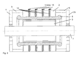
- the first four figures show an embodiment of an inventive cooling system for a rotating electrical machine highest power density, with fluid cooling and a closed coolant circuit in the stator 1, which here consists of five connected to tie rods spaced SterteilerteilblechMultien 2. Between SterteilblechMultien 2 is ever a cooling plate assembly 10 (here in the example, therefore, a total of four in this rotary electric machine) arranged as out FIG. 3 seen.
- FIG. 4 shows how the distribution of coolant supply and coolant removal takes place. Coolant supply takes place on one side of the machine via a central coolant main inlet 35 into a downstream coolant main distributor 33.
- stator cooling connection tubes 17 are connected to these main coolant distributor 33 arranged on the stator core 2, each of which is formed so long that it is in each case connected to a stator connecting piece makes the inlet 15 of a cooling plate assembly 10.
- the coolant is both radially distributed and guided inwardly, guided deflected outwards and leaves thedeteilblechune 10 via the stator connection piece for the expiry 16.
- the coolant removal of the heated coolant is carried out from thedeteilblechp 10 via individual another stator cooling connection pipes 17, which are connected to a coolant main collector 34 on the other opposite machine side. From this coolant main collector 34, the heated cooling medium is discharged via the coolant main drain 36.
- FIG. 2 shows twodekarleitbleche for the interior of adeteilblechps 10 with two identically formed against each other twisted and offset layereddekarleitblechen 13, which have a with the stator core 2 identical contour in the groove and tooth area.
- An analogue version shows FIG. 5 , where the interior of adeteilblechp 10 is shown for the rotor 3 of an induction machine.
- a constriction to form a volume flow symmetry 23 is arranged in the direction of the short distance to the stator connection piece for the outlet 15, so that a radial heat dissipation is possible radially and no thermal asymmetries arise.
- This bottleneck to the volume flow symmetry 23 may be omitted if, in a special case, the stator connection piece for the outlet 16 is arranged exactly opposite the stander connection piece for the inlet 15 offset by 180 degrees. Then the coolant flow would divide exactly halfway. However, this is relatively complicated in the production of the entire machine, which is why this special case production-wise rather no significance.
- In theisseratorieaubleblechen 13 here are the holes for the introduction of the tie rods 32 can be seen.
- the section AA again shows a cross section through four cooling part plates 11 (two boundary plates 12 and twodeffenleitbleche 13) in an assembled form as a cutout at the point where the cooling liquid from onedeleitblech 13 to the other cooling baffle 13 can flow through.
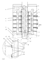
- FIG. 6 shows an induction machine with a cooling system according to the invention withdeteilblech Distribuen 10 both in the stator 1 and in the rotor 3.
- the supply of the cooling medium takes place here via axial rotor cooling connection pipes 18, which are fastened by means of screw soldering or welding connections in each case to a cooling medium part laminated core 10.
- Thedeatorileitbleche 13 have connection holes which are smaller than the recesses for the axial rotor cooling connection tubes 18 in the rotor lamination 3.
- a simple sheet metal section for the rotor core 4 is proposed, which in turn consists of two cover plates and two identicaldeffenleitblechen 13. Once set, solidification is again achieved by screwing, gluing, soldering, welding or pressing. It is also possible here to provide additional seals with between to ensure the fluid tightness permanently over the entire life of such a machine.
- a rotor cooling connection pipe 18 may also be arranged per cooling part laminated core 13 in the rotor. In FIG.
- each individual fluid-tight cooling part laminated core 10 is separately supplied with a rotor cooling connection pipe 18 with the cool cooling fluid, that is, six rotor cooling connection tubes 18 are formed for cooling fluid supply. These are usually arranged in a circular ring on a certain radius distributed radially in the rotor 3. It is z. B. the uppermostdeteilblechp 10 of the rotor 3 directly by means of a hollow screw 22, coupled via an expandable coupling and connecting piece 28 to the rotor connection element 21 and is acted upon via the rotor hollow shaft channel 20 and the rotor cooling channel 19 with cooling fluid.
- the rotor connection element 21 is likewise connected to the rotor cooling channel 19 via a hollow screw 22.
- the other five rotor cooling connection pipes 18 are formed radially distributed for cooling fluid discharge, which are coupled to the cooling plate assembly 10 via a hollow screw 22, thereby guided by the other rotor sub-packages or Läuferteilblechonge 4 and on the other hand via a cranked rotor connection element 21 via a inwardly directed rotor cooling channel 19 connected to the space around the siphon tube 27 and via the rotary leadthrough 26 to the rotor coolant main drain 37.
- the heated cooling fluid from the respective fluid-tightdeteilblechMultien 10 is again derived directly and performed on a direct path to the outside.
- the rotor hollow shaft channel 20 is arranged so that through this the cooling liquid via the at the rotary feedthrough 26th attached rotor coolant main supply 38 is supplied.
- the rotor fluid passes through a hollow screw 22 in the bent rotor connection element 21 via the rotor cooling duct 19 leading radially outwards through the rotor shaft.
- This rotor connection element 21 is connected to the rotor cooling connection pipe 18 by means of an expandable coupling and connection piece 28, which transfers the cooling liquid into the individual cooling part sheet packages 10 of the rotor 3 distributed over other special connecting and feeding elements.
- the cooling fluid now flows through thedeteilblechwovene 10 radially arcuately in both directions and is discharged via the oppositely disposed second rotor cooling connection tube 18 again.
- This in turn is connected to alldeteilblechmultien 10 of the rotor 3 at the appropriate locations.
- a series circuit of thedeteilblechwovene 10 is formed in the sheets of the rotor part package or Läufererteilblechongs 4 special recesses 24 for the rotor cooling connection pipes 18 are provided.
- the heated cooling medium is then passed via a radially inwardly leading rotor cooling channel 19, which opens into the space around the siphon tube 27, to the rotary feedthrough 26, on which the rotor coolant main drain 37 is arranged.
- the siphon tube 27 is guided through a rotary feedthrough 26 via which the coolant flows. Through the siphon tube 27 a safe separation ofchenzu- and coolant outlet is achieved.
- FIG. 1 shows fivedeteilbleche 11 in a preferred embodiment, of which two boundary plates 12 and threedeffenleitbleche for optimally cooling technology acting cooling plate assembly 10 for a stand 1.
- a special Axialleitblech 39 is arranged.
- This Axialleitblech 39 corresponds in shape exactly the sheet shape of the individual sheets of St Serteilblechpers 2 and causes primarily an axial flow guidance of the coolant inside theméteilblechpers 10.
- cooling system for a rotary electric machine highest power density, with fluid cooling in a closed coolant circuit in the stator and / or rotor, consisting of two or more interconnected partial laminated cores and wherein the partial laminated cores are spaced from each other and the runner from either solid part bodies or consists of laminated rotor laminations, there is a very effective cooling of electromagnetically active areas, ie the heat is dissipated directly in the immediate vicinity of the place of origin, without as sunday otherwise possible heat transfer over longer distances or several different materials must be made.
- FIG. 7 a cooling part plate 11 is shown, which is designed as a boundary plate 12.
- the two sealing grooves 44 are incorporated as circumferential grooves in the sheet material.
- the inner sealing groove 45 and also the outer sealing groove 46 can be produced for example by milling or electrical erosion.
- a continuous 0-ring made of rubber or another suitable sealing material, such as Viton is inserted into each sealing groove 44.
- FIG. 8 forms an assembly drawing of four individual superimposed, superimposed cooling part plates 11, which are connected to a cooling plate assembly 10 with each other.
- adeteilblechp 10 consisting of an internally arrangeddeatorileitblech 13 without Dichtungsnuten 44, an internally arrangeddekarleitblech 13 with two sealing grooves 44 and two outer boundary plates 12, each with an inner seal groove 45 and an outer seal groove 46 shown.
- the location and arrangement of the sealing grooves within a cooling plate assembly 10 is shown schematically.
Abstract
Description
Die Erfindung betrifft ein Kühlsystem für eine rotierende elektrische Maschine höchster Leistungsdichte mit Fluidkühlung in einem geschlossenen Kühlmittelkreislauf im Ständer und/oder im Läufer, bestehend aus zwei oder mehreren miteinander verbundenen Teilblechpaketen, wobei die Teilblechpakete voneinander beabstandet sind und der Läufer aus massiven Teilkörpern oder aus geblechten Läuferteilblechpaketen besteht.The invention relates to a cooling system for a rotary electric machine of highest power density with fluid cooling in a closed coolant circuit in the stator and / or in the rotor, consisting of two or more interconnected partial laminated cores, wherein the partial laminated cores are spaced from each other and the rotor of solid part bodies or of laminated Rotor part packages consists.
Elektrische Maschinen führen normalerweise die beim Betrieb entstehende Wärme über die Maschinengehäuseoberfläche an die Umgebungsluft ab. Für hochausgenutzte Maschinen ist es allerdings erforderlich die Wärme mittels Flüssigkeitskühlung abzuleiten. Dazu werden in der Regel Kühlrohre im Gehäuse angeordnet. Das Eingießen von Kühlrohren in Gehäuse rotierender elektrischer Maschinen ist in einer Vielzahl von verschiedenen Anwendungen allgemeiner Stand der Technik. Allerdings ist das Eingießen ein energetisch aufwändiger und Arbeitszeit aufwändiger komplizierter Prozess.Electrical machines normally dissipate the heat generated during operation to the ambient air via the machine housing surface. For highly used machines, however, it is necessary to dissipate the heat by means of liquid cooling. For this purpose, cooling tubes are usually arranged in the housing. The pouring of cooling tubes into housings of rotating electrical machines is well known in a variety of different applications. However, the pouring is an energy consuming and laborious complex process.
So ist z. B. aus der
Aus der
Aus der
Eine andere ähnliche Lösung ist in der
Die
Wie vorstehend beschrieben gibt es noch eine weitere Vielzahl von rotierenden elektrischen Maschinen, welche allein durch einen Wassermantel gekühlt werden. Mittels dieser Wassermantelkühlung kann im besten Fall eine zulässige Verlustleistung je Eisenpaketlänge von ca. 20 bis 25 W/mm erreicht werden. Allein mit Wassermantelkühlung ist daher eine sehr intensive Kühlung in den besonders thermisch hoch beanspruchten aktiven Bereichen einer rotierenden elektrischen Maschine nicht ausreichend realisierbar.As described above, there are still another variety of rotary electric machines cooled by a water jacket alone. By means of this water jacket cooling, a permissible power loss per iron core length of approximately 20 to 25 W / mm can be achieved in the best case. Therefore, with water jacket cooling, it is not possible to sufficiently realize very intensive cooling in the active regions of a rotating electrical machine that are particularly subject to high thermal stress.
In der
Eine deutliche Verbesserung ist mit der technischen Lösung gemäß
Eine weitere Lösung zur Steigerung der zulässigen Verlustdichte wurde mit der technischen Lösung gemäß der
Durchzugsbelüftete intensiv gekühlte elektrische Maschinen erreichen die bisher höchsten Verlustdichten. Das Verhältnis von zulässiger Verlustleistung zu Eisenpaketlänge liegt hier sogar zwischen 20... 35W/mm je nach Maschinengröße und realisierten Kühlsystem. Durch
Ein anderes universelles Kühlsystem mit Durchzugskühlung ist in der
Der Erfindung liegt die Aufgabe zugrunde ein Kühlsystem für eine rotierende elektrische Maschine mittlerer Leistung und mit höchster Leistungsdichte mit Fluidkühlung zu schaffen, welche sich durch eine kompakte und leichte Bauweise auszeichnet, wobei die Maschine aus zwei oder mehreren miteinander verbundenen Teilblechpaketen besteht, und dass ein geschlossener Kühlmittelkreislauf im Ständer und/oder im Läufer ermöglicht wird, wobei dass erwärmte Kühlmedium so schnell als möglich aus der Maschine abgeführt werden soll, eine konstante Temperaturverteilung über der gesamten axialen Länge der Maschine gewährleistet ist, eine deutlich höhere thermischen Belastung von bis zu 70W/mm erreichbar ist und wobei ein minimales Gewicht je kW-Wellenleistung erreicht werden soll.The invention has for its object to provide a cooling system for a rotary electric machine medium power and highest power density with fluid cooling, which is characterized by a compact and lightweight design, the machine consists of two or more interconnected partial laminated cores, and that a closed Coolant circuit in the stator and / or in the rotor is made possible, wherein the heated cooling medium is to be removed as quickly as possible from the machine, a constant temperature distribution over the entire axial length of the machine is guaranteed, a significantly higher thermal load of up to 70W / mm is achievable and with a minimum weight per kW shaft power to be achieved.
Die Aufgabe der Erfindung wird durch die Merkmale des 1. Patentanspruchs gelöst. Weitere zweckmäßige Ausgestaltungen der Erfindung sind Gegenstand der rückbezüglichen Unteransprüche. Das neuartige erfindungsgemäße Kühlsystem für eine rotierende elektrische Maschine höchster Leistungsdichte basiert auf einer Fluidkühlung mit einem geschlossenen Kühlmittelkreislauf im Ständer und/oder im Läufer. Der Ständer besteht dabei aus mindestens zwei oder mehreren miteinander in bekannter Art und Weise verbundenen Teilblechpaketen, wobei die Teilblechpakete voneinander definiert beabstandet sind. Der Läufer kann entweder aus einem oder auch aus mehreren voneinander definiert beabstandeten massiven Teilkörpern oder auch aus geblechten Läuferteilblechpaketen bestehen. Zwischen den Ständerteilblechpaketen 2 und/oder den Läuferteilpaketen (bei massiven Läuferkörpern) und/oder Läuferteilblechpaketen 4 sind neuartige fluiddichte Kühlteilblechpakete 10 angeordnet. Diese Kühlteilblechpakete 10 sind vollkommen fluiddicht ausgebildet und bestehen aus mindestens drei Kühlteilblechen 11. Die fluiddichten Kühlteilblechpakete 10 werden von einem Kühlfluid durchströmt und die Kühlteilblechpakete 10 sind einzeln oder untereinander mit einem Kühlmittelhauptzufluss 35 und einem Kühlmittelhauptabfluss 36 verbunden angeordnet.The object of the invention is solved by the features of the first claim. Further expedient embodiments of the invention are the subject of the rückbezügenden dependent claims. The novel cooling system according to the invention for a rotating electrical machine of highest power density is based on fluid cooling with a closed coolant circuit in the stator and / or in the rotor. The stand consists of at least two or more interconnected in a known manner partial laminated cores, wherein the partial laminated cores are spaced from each other defined. The runner may consist of either one or a plurality of mutually spaced-apart solid partial bodies or of laminated rotor sub-laminated cores. Between the stator
Durch das neuartige Kühlsystem ist es erstmals möglich zwischen den Ständerteilblechpaketen 2 und/oder Läuferteilpaketen oder Läuferteilblechpaketen 4 eine voll wirksame Kühlung nicht nur des passiven Eisenkreises, sondern auch im Bereich des Entstehens der Verlustwärme am aktiven Material, d. h. der Wicklung zu realisieren, da die Wicklung von den Nutteilen der fluiddichten Kühlteilblechpakete 10 analog umfasst ist. Dadurch kann die entstehende Wärme aus der Wicklung auf sehr kurzem Weg in das Kühlfluid abgeleitet werden. Das neuartige Kühlsystem ist besonders zur Kühlung von Ständerblechpaketen für rotierende gehäuselose elektrische Maschinen geeignet. Es kann jedoch auch genauso zur Kühlung von Läuferteilpaket (bei massiven Läuferkörpern) oder Läuferteilblechpaketen verwendet werden. Hierfür ist dann entsprechend eine bestimmte Anzahl von axialen Kanälen im Läuferjochbereich vorzusehen. Des Weiteren ist es möglich durch dieses Kühlsystem die Maschine bei gleicher Leistung eine Achshöhe kleiner zu bauen, was zu einem günstigen Masse-Oberflächenverhältnis führt. Auch bei großen axialen Baulängen zum Beispiel bei speziellen Induktionsmotoren entsteht kein axialer Temperaturanstieg über die gesamte Länge des Ständers der Maschine betrachtet. Durch die im Inneren des erfindungsgemäßen Kühlsystems realisierte große Oberfläche ist eine sehr gute Wärmeabführung aus den aktiven Bereichen über die Kühlteilblechpakete 10 möglich.Due to the novel cooling system, it is now possible between the
Bevorzugt besteht das fluiddichte Kühlteilblechpaket 10 des neuartigen Kühlsystems für eine rotierende elektrische Maschine höchster Leistungsdichte aus vier Kühlteilblechen 11. Dabei ist jeweils links und rechts außen je ein Begrenzungsblech 12 und innen zwei Kühlmittelleitbleche 13 angeordnet und miteinander verbunden. Es ist aber auch prinzipiell möglich in Abhängigkeit z. B. von der Größe der rotierenden elektrischen Maschine innen drei oder noch mehr Kühlmittelleitbleche 13 anzuordnen und dieses Kühlteilblechpaket 10 dann fluiddicht zu verbinden. Zum Erreichen eines geschlossenen Kreislaufs innen in den Kühlmittelleitblechen 13 werden verschieden ausgeschnittene Bleche formschlüssig miteinander verbunden. Diese Kühlmittelleitbleche 13 mit einer speziell ausgebildeten Innenkontur können wahlweise durch Fräsen Stanzen, Lasern oder Erodieren aus einer entsprechenden Blechtafel herausgetrennt werden. Diese Innenkontur dient dabei der Führung eines eingesetzten Kühlfluids.Preferably, the fluid-tight cooling part laminated
Eine besonders gute Wärmeausleitung aus den aktiven Bereichen beim erfindungsgemäßen Kühlsystem wird erreicht, wenn die fluiddichten Kühlteilblechpakete 10 im Ständer 1 und/oder im Läufer 3 die gleiche Innerkontur, wie Zähne, Nuten und/oder Aussparungen aufweisen, wie die Ständerteilblechpakete 2 und/oder Läuferteilpakete oder Läuferteilblechpakete 4.A particularly good heat dissipation from the active areas in the cooling system according to the invention is achieved when the fluid-tight cooling part laminated
Wenn beim Kühlsystem für eine rotierende elektrische Maschine höchster Leistungsdichte die fluiddichten Kühlteilblechpakete 10 aus zwei Begrenzungsblechen 12 und ein, zwei oder mehreren Kühlmittelleitblechen 13 bestehen sind die Kühlmittelteilblechpakete jeweils mit mindestens einem Anschluss zur Fluidzufuhr und gleichfalls wieder zur Fluidabfuhr ausgebildet. Der Anschluss kann in einfacher Art und Weise über axial oder radial angeordnete Hohlschrauben mit bekannten Hydraulikleitungen erfolgen.If in the cooling system for a rotary electric machine highest power density, the fluid-
Bevorzugt sind beim neuartigen Kühlsystem für eine rotierende elektrische Maschine höchster Leistungsdichte die Kühlteilbleche 11 des fluiddichten Kühlteilblechpakets 10 untereinander Leistungsdichte die Kühlteilbleche 11 des fluiddichten Kühlteilblechpakets 10 untereinander mittels einer Löt-, Schweiß-, Kleb- und/oder Pressverbindung abdichtend verbunden. Das Verbinden der vier oder auch von mehreren Kühlteilblechen 11 zu einem fluiddichten Kühlteilblechpaket 10 erfolgt mit einem speziellen Fügeprozess wie z. B. mittels Kleben, Löten oder Schweißen oder Pressen. Bei Bedarf ist es auch denkbar zusätzliche Dichtungen zwischen den Kühlteilblechen 11 einzulegen. Als Möglichkeit sei hier das Verlöten von Kühlteilblechen 11 aus Aluminium genannt, welche durch ein Plasma-Beschichtungsverfahren über Vermittlerschichten untereinander lötbar verbunden werden können, wobei das Kühlteilblechpaket 10 gleichzeitig insgesamt fluiddicht ausgebildet werden kann. Hierdurch entsteht eine gute Wärmeleitung der Kühlteilbleche 11 untereinander.In the novel cooling system for a rotary electric machine of highest power density, the cooling
In einer besonders vorteilhaften Ausführung der Kühlmittelleitbleche 13 für das Kühlsystem ist an einer oder mehreren Stellen der Strömungsquerschnitt der fluiddichten Kühlmittelleitbleche 13 durch entsprechend dimensionierte Engstellen zur Volumenstromsymmetrie 23 verengt ausgebildet. Durch diese Engstellen wird der Strom des Kühlfluides auf eine bestimmte Menge pro Zeiteinheit reduziert und gleichzeitig wird der Kühlfluidstrom symmetrisch in den Kühlteilblechpaketen 10 so geführt, dass eine sehr gleichmäßige und konstante Temperaturverteilung im Kreisring entsteht.In a particularly advantageous embodiment of the
Wenn das erfindungsgemäße Kühlsystem für eine rotierende elektrische Maschine auch im Läufer angeordnet ist, sind die fluiddichten Kühlteilblechpakete 10 durch ein, zwei oder mehrere axial im Läuferteilpaket oder im Läuferteilblechpaket 4 angeordnete Läuferkühlverbindungsrohre 18 untereinander verbunden und werden über diese mit einem Kühlfluid beaufschlagt. Dabei ist das bzw. sind die Läuferkühlverbindungsrohre 18 mit Läuferkühlkanälen 19 mit einem Läuferkühlmittelhauptabfluss 37 und über einen Läuferhohlwellenkanal 20 mit einem Läuferkühlmittelhauptzufluss 38 so verbunden, dass jedes einzelne Kühlteilblechpaket 10 einzeln getrennt von den anderen mit noch kühlen Kühlfluid versorgt wird und aus jedem einzelnen Kühlteilblechpaket 10 das erwärmte Kühlfluid auch einzeln getrennt von den anderen über Läuferkühlverbindungsrohre 18, die radial verteilt im Läufer 3 angeordnet sind, abgeführt wird.If the cooling system according to the invention for a rotating electric machine is also arranged in the rotor, the fluid-tight cooling part laminated
Beim fluiddichten Kühlteilblechpaket 10 des Kühlsystems bestehen die Kühlteilbleche 11, d. h. die Begrenzungsbleche 12 und/oder die Kühlmittelleitbleche 13 aus Aluminium, oder Kupfer, oder aus Elektroblech oder aus Dichtungswerkstoffen oder gegebenenfalls auch aus einer Kombination dieser Werkstoffe. Die Kühlteilbleche 11 können hierbei auch aus dem gleichen Elektroblech wie die Blechpakete oder auch aus elektrisch und thermisch leitfähigeren Materialien oder allein aus Dichtungsmaterialien bestehen. Insbesondere eignen sich hier relativ leichte Werkstoffe, wie Aluminium. Es ist auch möglich zwischen den einzelnen Kühlteilblechen 11 des Kühlteilblechpaketes 10 zum Beispiel außen am Umfang in Randnähe und innen im Bereich der Durchführungen, wie z. B. für die Zuganker vorgefertigte (ausgestanzte) Dichtungen aus geeigneten handelsüblichen Dichtungsmaterialien einzulegen um für die sehr lange währende Lebensdauer solcherart ausgebildeter rotierender elektrischer Maschinen die Fluiddichtigkeit zuverlässig zu gewährleisten.In the case of the fluid-tight cooling part laminated
Um das Kühlsystem für eine rotierende elektrische Maschine höchster Leistungsdichte optimal mit einem Kühlfluid zu versorgen, sind die fluiddichten Kühlteilblechpakete 10 außerhalb des Ständers 1 oder innerhalb des Ständers 1 mittels Ständerkühlverbindungsrohren 17 mit einem Kühlmittelhauptverteiler 33 und einem Kühlmittelhauptsammler 34 verbunden. An diesen ist dann ein Kühlmittelhauptzufluss 35 bzw. ein Kühlmittelhauptabfluss 36 mit entsprechendem Rohrquerschnitt angeordnet. Analog ist im Läufer dann bei Anwendung des erfindungsgemäßen Kühlsystems auch im Läufer an der Läuferwelle 7 je ein Läuferkühlmittelhauptzufluss 38 bzw. ein Läuferkühlmittelhauptabfluss 37 angeordnet.In order to optimally supply the cooling system for a rotating electrical machine of highest power density with a cooling fluid, the fluid-tight cooling part laminated
Eine besonders effektive Kühlung mittels des erfindungsgemäßen Kühlsystems kann erreicht werden, wenn das Kühlteilblechpaket 10 aus mindestens fünfKühlteilblechen 11 besteht. Dabei ist links und rechts außen das Kühlteilblechpaket 10 mit mindestens zwei Begrenzungsblechen 12 gegenüber den anliegenden Teilblechpaketen begrenzt und abgedichtet. Weiter innen sind links und rechts mindestens zwei speziell gestaltete Kühlmittelleitbleche 13 und mindestens mittig ein Axialleitblech 39 untereinander flüssigkeitsdicht verbunden. Dabei ist ein System von untereinander verbundenen Kühlmittelleitblechfenstern zur Kühlmittelführung 14 realisiert, wobei speziell geformte darauf abgestimmten Öffnungen 42, wieder darauf abgestimmte Anordnungen von Langlöchern 41 und damit verbunden angeordnete Teilkanäle 43 und Bohrungen 40 so angeordnet sind, dass im Kreisring im Inneren des Kühlteilblechpaketes 10 eine kreisbogenförmige, radiale und axiale Zwangsführung eines zugeführten Kühlmediums vom Ständeranschlussstutzen für den Zulauf 15 bis in die Zahnköpfe des Kühlteilblechpaketes 10 und wieder zurück bis zum Ständeranschlussstutzen für den Ablauf 16 erfolgt. Die Kühlmittelleitbleche 13 und das Axialblech 39 können allerdings auch mehrfach angeordnet werden. Gleichfalls sind zum Beispiel anstelle je eines dickeren Begrenzungsbleches 12 auch mehrere dünnere Begrenzungsbleche 12 einsetzbar. Mittels dieses Systems wird der Kühlmittelstrom, der axial zugeführt wird, in dem einen (z. B. links vom Axialleitblech 39 angeordneten) Kühlmittelleitblech 13 und mittels des Axialleitblechs 39, erst radial nach Innen geführt, dann kreisbogenförmig entlang des äußeren Umfangs des Kühlteilblechpakets 13 mittels der Kühlmittelleitblechfensters zur Kühlmittelführung 14 in Verbindung mit den Öffnungen 42 verteilt, dann radial nach Innen geführt, dann axial und radial nach Innen mittels der Langlöcher 41 umgelenkt, dann um den Nutgrund mittels der Teilkanäle 43 geführt, strömt dann radial nach innen bis in die Zahnköpfe, wird dann mittels der Bohrungen 40 des Axialleitblechs 39 axial umgelenkt, dann wieder radial nach außen mittels der Teilkanäle 41 des anderen (z. B. rechts vom Axialleitblech 39 angeordneten) Kühlmittelleitblechs 13 geführt, dann erneut entlang des Nutgrundes, dann radial nach außen geführt, strömt axial und dann radial nach außen mittels anderer Langlöcher 41 des Axialleitblechs 39, wird wieder kreisbogenförmig mittels der Kühlmittelleitblechfenstern zur Kühlmittelführung 14 des zweiten Kühlmittelleitblechs 13 umgelenkt und geführt und strömt dann radial nach außen, um wieder Axial abgeleitet zu werden.A particularly effective cooling by means of the cooling system according to the invention can be achieved if the cooling-part
Für rotierende elektrische Maschinen höchster Leistungsdichte mit lang bauenden Blechpaketen ist das von Vorteil, wenn das Kühlsystem so ausgebildet ist, dass die Breite der einzelnen Kühlteilblechpakete 10 variiert werden kann. Vor allem in der Mitte werden solche Maschinen besonders warm. Diese Wärme kann gut abgeleitet werden, wenn das in der Maschinenmitte angeordnete Kühlteilblechpaket 10 breiter ausgebildet ist. Es ist auch möglich von den Maschinenenden zur Mitte hin die Kühlteilblechpakete 10 des Ständerblechpaketes 2 und/oder Läuferblechpaketes 4 jeweils immer breiter werden zu lassen, wodurch mehr Kühlffluid durch diese Kühlteilblechpakete durchströmen kann und dadurch die Kühlung zur Maschinenmitte diese Kühlteilblechpakete durchströmen kann und dadurch die Kühlung zur Maschinenmitte hin immer effektiver wird. Dadurch können thermische Unsymmetrien, über die gesamte Länge des Blechpaketes betrachtet, zuverlässig vermieden werden.For rotating electrical machines of highest power density with long-stacking laminated cores, this is advantageous if the cooling system is designed such that the width of the individual cooling-
In einer besonderen Variante des erfindungsgemäßen Kühlsystems für eine rotierende elektrische Maschine höchster Leistungsdichte sind pro Kühlteilblech 11 einseitig nach Innen gerichtet mindestens zwei Dichtungsnuten 44 ausgespart und angeordnet. Dabei ist der Durchmesser der kreisringartigen inneren Dichtungsnut 45 kleiner als der Durchmesser des Kreisrings in dem die Kühlmittelleitblechfenster zur Kühlmittelführung 14 angeordnet sind. Der Durchmesser der äußeren Dichtungsnut 46 ist größer als der Durchmesser des Kreisrings in dem die Kühlmittelleitblechfenster zur Kühlmittelführung 14 angeordnet sind, wobei diese Dichtungsnut 46 der Außenkontur des jeweils betreffenden Kühlteilbleches 11 entlang folgt und von dessen Rand nur geringfügig beabstandet ausgespart und angeordnet ist. In diese Dichtungsnuten 44 sind jeweils 0-Ringe eingelegt, so dass das Kühlteilblechpaket 10 in seinem Inneren zusätzlich durch diese 0-Ringdichtungen abgedichtet ist. Bei Bedarf kann der Kleber zwischen den Oberflächen der Kühlteilbleche 11 gegebenenfalls auch weggelassen werden. Diese Lösung ist zwar fertigungstechnisch etwas aufwändiger, ist aber auch unter schwierigsten Bedingungen einsetzbar und erzeugt eine dauerhafte Dichtigkeit auch unabhängig von den jeweiligen Einsatzorten einer solcherart ausgebildeten elektrischen Maschine. Durch den möglichen Wegfall des Klebers zwischen den einzelnen Kühlteilblechen 11 verbessert sich der Wärmeübergang zwischen den Kühlteilblechen 11. Außerdem kann in diesem Fall der Querschnitt der Kühlmittelteilblechfenster 14 erheblich vergrößert werden. Damit erhöht sich der Strömungsquerschnitt und der Kühlmitteldurchsatz kann ebenfalls weiter verbessert werden. Darüber hinaus ist dadurch eine klassische Stanzform der Kühlmittelteilblechfenster 14, wie bei durchzugsbelüfteten elektrischen Maschinen an sich üblich, in einfacher Art und Weise realisierbar. Im Prinzip können die Dichtungsnuten 44 auch auf beiden Seiten der Kühlteilbleche 14 ausgespart und angeordnet werden, wobei die Durchmesser dann auf der Vorder- und Rückseite unterschiedlich sein sollten, damit sich die jeweils inneren oder äußeren Dichtungsnuten 45 und 46 nicht symmetrisch gegenüberliegen und damit eine ausreichende Dicke der Kühlteilbleche 14 an diesen Stellen erhalten bleibt.In a particular variant of the cooling system according to the invention for a rotating electrical machine of the highest power density, at least two sealing
Das erfindungsgemäße Kühlsystem soll nachstehend in einem Ausführungsbeispiel an Hand der
Figur 1- zeigt fünf Kühlteilbleche 11 in bevorzugter Ausführung, davon zwei Begrenzungsbleche 12 und drei Kühlmittelleitbleche 13 für
ein Kühlteilblechpaket 10 für einen Ständer 1 Figur 2- zeigt
ein Kühlteilblechpaket 10 in einer zweiten Ausführung mit zwei identischen gegeneinander verdreht und versetzt geschichteten Kühlmittelleitblechen 13 miteiner dem Ständerblechpaket 2 identischer Kontur im Nut und Zahnbereich Figur 3- zeigt ein erfindungsgemäßes Kühlsystem für eine rotierende elektrische Maschine mit
Anordnung mehrerer Kühlteilblechpakete 10 ineinem Ständer 1 Figur 4- zeigt die
Anordnung der Kühlteilblechpakete 10im Ständer 1 und eine mögliche Anordnung zur Verteilung der Kühlmittelzufuhr und Kühlmittelabfuhr auf demGrundkörper eines Ständers 1 Figur 5- zeigt das Innere eines Kühlteilblechpakets 10 für
den Läufer 3 mit zwei identisch ausgebildeten und verdreht geschichteten Kühlmittelleitblechen 13 Figur 6- zeigt die Anordnung mehrerer Kühlteilblechpakete 10 und deren
Anschlussgestaltung im Läufer 3 und eine Gesamtdarstellung des erfindungsgemäßen Kühlsystemsim Ständer 1 und Läufer 3 Figur 7- zeigt eine Kühlteilblech 11, welches
als Begrenzungsblech 12 ausgeführt ist Figur 8- zeigt eine Kühlteilblech 11, welches
als Kühlmittelleitblech 13 ausgeführt ist und einen Schnitt der einen Querschnitt durchein Kühlteilblechpaket 10mit den Dichtungsnuten 44 in denen 0-Ringe eingelegt sind
- FIG. 1
- shows five
cooling part plates 11 in a preferred embodiment, of which twoboundary plates 12 and threeKühlmittelleitbleche 13 for a cooling part laminatedcore 10 for a stand first - FIG. 2
- shows a cooling part laminated
core 10 in a second embodiment with two identical against each other twisted and offset layeredKühlmittelleithblechen 13 with astator core 2 identical contour in the groove and tooth area - FIG. 3
- shows a cooling system according to the invention for a rotating electrical machine with arrangement of several cooling part lamination packages 10 in a stand first
- FIG. 4
- shows the arrangement of the
Kühlteilblechpakete 10 in thestator 1 and a possible arrangement for distribution of the coolant supply and coolant discharge on the body of a stator first - FIG. 5
- shows the interior of a
Kühlteilblechpaket 10 for therotor 3 with two identically designed and twisted laminated Kühlmittelleithblechen 13th - FIG. 6
- shows the arrangement of a plurality of
Kühlteilblechpakete 10 and their connection design in therotor 3 and an overall view of the cooling system according to the invention in thestator - FIG. 7
- shows a cooling
part plate 11, which is designed as aboundary plate 12 - FIG. 8
- shows a cooling
part plate 11, which is designed asKühlmittelleitblech 13 and a section of a cross section through a coolingplate assembly 10 with the sealinggrooves 44 in which 0-rings are inserted
Die ersten vier Figuren zeigen ein Ausführungsbeispiel für ein erfindungsgemäßes Kühlsystem für eine rotierende elektrische Maschine höchster Leistungsdichte, mit Fluidkühlung und einem geschlossenen Kühlmittelkreislauf im Ständer 1, der hier aus fünf mit Zugankern verbundenen voneinander beabstandeten Ständerteilblechpaketen 2 besteht. Zwischen den Ständerteilblechpaketen 2 ist je ein Kühlteilblechpaket 10 (hier im Beispiel daher insgesamt vier in dieser rotierenden elektrischen Maschine) angeordnet, wie aus
In einer anderen einfacheren aber kühltechnisch nicht so effektiv wirkenden Lösung sind nur zwei durchgehende Läuferkühlverbindungsrohre 18 größeren Querschnitts im Läufer 3 angeordnet, wobei diese alle Kühlteilblechpakete 10 untereinander verbinden. Diese zwei durchgehenden Läuferkühlverbindungsrohre 18 sind jeweils genau um 180 Grad versetzt angeordnet und sind durch alle Läuferteilpakete bzw. Läuferteilblechpakete 4 geführt. In diesen Läuferteilpaketen bzw. Läuferteilblechpakete 4 befinden sich an entsprechender Stelle entsprechende Öffnungen. Ein Läuferkühlverbindungsrohr 18 wirkt dabei als Zuleitkanal und eines als Ableitkanal für die Kühlflüssigkeit. Die Läuferwelle 7 ist hier gleichfalls als Läuferhohlwelle 8 ausgeführt. In dieser Läuferhohlwelle 8 ist der Läuferhohlwellenkanal 20 so angeordnet, dass durch diesen die Kühlflüssigkeit über den an der Drehdurchführung 26 angebrachten Läuferkühlmittelhauptzufluss 38 zugeführt wird. Über den radial nach außen durch die Läuferwelle führenden Läuferkühlkanal 19 gelangt die Kühlflüssigkeit durch eine Hohlschraube 22 in das abgekröpfte Läuferanschlusselement 21. Dieses Läuferanschlusselement 21 ist mittels eines dehnbaren Kupplungs- und Verbindungsstücks 28 mit dem Läuferkühlverbindungsrohr 18 verbunden, welches die Kühlflüssigkeit in die einzelnen Kühlteilblechpakete 10 des Läufers 3 über weitere spezielle Verbindungs- und Zuführelemente verteilt. Das Kühlfluid durchfließt nun die Kühlteilblechpakete 10 radial kreisbogenförmig in beide Richtungen und wird über das gegenüber angeordnete zweite Läuferkühlverbindungsrohr 18 wieder abgeführt. Dieses ist wiederum mit allen Kühlteilblechpaketen 10 des Läufers 3 an den entsprechenden Stellen verbunden. Dabei entsteht in diesem Fall eine Reihenschaltung der Kühlteilblechpakete 10. In den Blechen des Läuferteilpakets oder Läuferteilblechpakets 4 sind spezielle Aussparungen 24 für die Läuferkühlverbindungsrohre 18 vorgesehen. Das erwärmte Kühlmedium wird nun über einen radial nach innen führenden Läuferkühlkanal 19, das in den Raum um das Siphonrohr 27 mündet, zur Drehdurchführung 26 geleitet, an welchem der Läuferkühlmittelhauptabfluss 37 angeordnet ist. Das Siphonrohr 27 ist durch eine Drehdurchführung 26 geführt über die das Kühlmittel zuströmt. Durch das Siphonrohr 27 wird eine sichere Abtrennung von Kühlmittelzu- und Kühlmittelablauf erreicht.In another simpler but not so effective cooling solution, only two continuous rotor
In
- 11
- Ständerstand
- 22
- StänderteilblechpaketStand partial laminated core
- 33
- Läuferrunner
- 44
- Läuferteilpaket oder LäuferteilblechpaketRotor section package or rotor section package
- 55
- Ständerwicklungstator winding
- 66
- Läuferwicklungrotor winding
- 77
- Läuferwellerotor shaft
- 88th
- LäuferhohlwelleRunners hollow shaft
- 99
- Pressrahmenpress frame
- 1010
- KühlteilblechpaketRefrigerator laminated core
- 1111
- KühlteilblechRefrigerator sheet
- 1212
- Begrenzungsblechlimiting sheet
- 1313
- Kühlmittelleitblechcoolant baffle
- 1414
- Kühlmittelleitblechfenster zur KühlmittelführungCoolant sheet metal window for coolant guidance
- 1515
- Ständeranschlussstutzen für ZulaufPost connection for inlet
- 1616
- Ständeranschlussstutzen für AblaufStand connecting piece for drain
- 1717
- StänderkühlverbindungsrohrStator cooling connecting pipe
- 1818
- LäuferkühlverbindungsrohrRotor cooling connecting pipe
- 1919
- LäuferkühlkanalRotor cooling channel
- 2020
- LäuferhohlwellenkanalRunners hollow shaft channel
- 2121
- LäuferanschlusselementRunner terminal
- 2222
- HohlschraubeHohlschraube
- 2323
- Engstelle für VolumenstromsymmetrieBottleneck for volume flow symmetry
- 2424
- Aussparungen für LäuferkühlverbindungsrohrRecesses for rotor cooling connection pipe
- 2525
- LäuferanschlussstutzenRunners spigot
- 2626
- DrehdurchführungRotary union
- 2727
- Siphonrohrsiphon tube
- 2828
- Dehnbares Kupplungs- und VerbindungsstückStretchable coupling and connection piece
- 2929
- Lagerschildend shield
- 3030
- Strömungsverlauf im StänderFlow in the stand
- 3131
- Strömungsverlauf im LäuferFlow in the runner
- 3232
- Bohrung für ZugankerBore for tie rods
- 3333
- KühlmittelhauptverteilerCoolant main distribution
- 3434
- KühlmittelhauptsammlerCoolant main collector
- 3 53 5
- KühlmittelhauptzuflussCoolant main tributary
- 3636
- KühlmittelhauptabflussCoolant main drain
- 3737
- LäuferkühlmittelhauptabflussRunners coolant main drain
- 3838
- LäuferkühlmittelhauptzuflussRunners coolant main tributary
- 3939
- AxialleitblechAxialleitblech
- 4040
- Bohrungendrilling
- 4141
- Langlöcherslots
- 4242
- Öffnungenopenings
- 4343
- Teilkanalsubchannel
- 4444
- Dichtungsnutenseal grooves
- 4545
- innere Dichtungsnutinner sealing groove
- 4646
- äußere Dichtungsnutouter sealing groove
Claims (12)
wobei die Teilblechpakete voneinander beabstandet sind und
der Läufer aus massiven Teilkörpern oder aus geblechten Läuferteilblechpaketen besteht, dadurch gekennzeichnet,
dass zwischen den Ständerteilblechpaketen (2) und/oder den Läuferteilpaketen und/oder Läuferteilblechpaketen (4) fluiddichte Kühlteilblechpakete (10) angeordnet sind,
diese fluiddichten Kühlteilblechpakete (10) aus mindestens drei Kühlteilblechen (11) bestehen, die fluiddichten Kühlteilblechpakete (10) von einem Kühlfluid durchströmt werden und
die Kühlteilblechpakete (10) einzeln oder untereinander mit einem Kühlmittelhauptzufluss (35) und einem Kühlmittelhauptabfluss (36) verbunden angeordnet sind.Cooling system for a rotating electrical machine of highest power density, with fluid cooling in a closed coolant circuit in the stator and / or in the rotor, consisting of two or more interconnected partial laminated cores,
wherein the partial laminated cores are spaced from each other and
the runner consists of solid part bodies or of laminated rotor sub-laminated cores, characterized
in that fluid-tight cooling-part laminated cores (10) are arranged between the stator-part laminated cores (2) and / or the rotor-part packages and / or rotor-part laminated cores (4),
these fluid-tight cooling part laminated cores (10) consist of at least three cooling part plates (11), the fluid-tight cooling part sheet packets (10) are flowed through by a cooling fluid and
the Kühlteilblechpakete (10) individually or with each other with a coolant main inlet (35) and a main coolant drain (36) are arranged.
dadurch gekennzeichnet,
dass das fluiddichte Kühlteilblechpaket (10) aus vier Kühlteilblechen (11) besteht.Cooling system for a high-power rotary electric machine according to claim 1,
characterized,
that the cooling fluid tight partial laminated core (10) consists of four cooling sheets part (11).
dadurch gekennzeichnet,
dass die fluiddichten Kühlteilblechpakete (10) im Ständer (1) und/oder im Läufer (3) die gleiche Innerkontur, wie Zähne, Nuten und/oder Aussparungen aufweisen, wie die Ständerteilblechpakete (2) und/oder Läuferteilpakete oder Läuferteilblechpakete (4).Cooling system for a high-power rotary electric machine according to claim 1,
characterized,
in that the fluid-tight cooling part laminated cores (10) in the stator (1) and / or in the rotor (3) have the same inner contour as teeth, grooves and / or recesses, such as the stator sub-laminated cores (2) and / or rotor sub-packages or rotor sub-laminated cores (4).
dadurch gekennzeichnet,
dass die fluiddichten Kühlteilblechpakete (10) aus zwei Begrenzungsblechen (12) und ein, zwei oder mehreren Kühlmittelleitblechen (13) bestehen und mit Anschlüssen zur Fluidzufuhr oder Fluidabfuhr versehen sind.Cooling system for a high-power rotary electric machine according to claims 1 and 3,
characterized,
that the fluid-tight cooling laminated-core assemblies (10) consists of two boundary plates (12) and one, two or more Kühlmittelleitblechen (13) and are provided with connections for fluid supply or fluid discharge.
dadurch gekennzeichnet,
dass die Kühlteilbleche (11) des fluiddichten Kühlteilblechpakets (10) untereinander mittels einer Löt-, Schweiß-, Kleb- und/oder Pressverbindung verbunden ausgebildet sind.Cooling system for a high-power rotary electric machine according to claim 1,
characterized,
that the cooling part plates (11) of the cooling fluid-tight partial laminated core (10) are formed connected to one another by means of a soldering, welding, adhesive and / or press-fit connection.
dadurch gekennzeichnet,
dass an einer oder mehreren Stellen der Strömungsquerschnitt der fluiddichten Kühlmittelleitbleche (13) durch Engstellen zur Volumenstromsymmetrie (23) verengt ausgebildet sind.Cooling system for a high-power rotary electric machine according to claim 1,
characterized,
in that the flow cross-section of the fluid-tight Kühlmittelleitbleche (13) are narrowed at one or more points by bottlenecks to the volume flow symmetry (23).
dadurch gekennzeichnet,
dass im Läufer die fluiddichten Kühlteilblechpakete (10) durch ein, zwei oder mehrere axial im Läuferteilpaket oder im Läuferteilblechpaket (4) angeordnete Läuferkühlverbindungsrohre (18) verbunden sind und dass das oder die Läuferkühlverbindungsrohre (18) mit Läuferkühlkanälen (19) mit einem Läuferkühlmittelhauptzufluss (38) und über einen Läuferhohlwellenkanal (20) mit einem Läuferkühlmittelhauptabfluss (37) verbunden sind.Cooling system for a high-power rotary electric machine according to claim 1,
characterized,
that the fluid-tight cooling laminated-core assemblies (10) by one, two or more axially in the rotor part package, or in the rotor part of the laminated core (4) disposed rotor cooling connecting pipes (18) are connected in the rotor and that the or the rotor cooling connecting pipes (18) with rotor cooling channels (19) (with a rotor main coolant inflow 38 ) and a rotor hollow shaft passage (20) are connected to a rotor coolant main drain (37).
dadurch gekennzeichnet,
dass die fluiddichten Kühlteilblechpakete (10), die Kühlteilbleche (11) die Begrenzungsbleche (12) und/oder die Kühlmittelleitbleche (13) aus Aluminium, oder Kupfer, oder aus Elektroblech oder aus Dichtungswerkstoffen oder aus einer Kombination aus diesen Werkstoffen bestehen.Cooling system for a high-power rotary electric machine according to one of the preceding claims,
characterized,
in that the fluid-tight cooling part laminated cores (10), the cooling part sheets (11), the boundary plates (12) and / or the Kühlmittelleitbleche (13) made of aluminum, or copper, or of electrical sheet or sealing materials or a combination of these materials.
dadurch gekennzeichnet,
dass die fluiddichten Kühlteilblechpakete (10) außerhalb des Ständers (1) oder innerhalb des Ständers (1) mittels Ständerkühlverbindungsrohren (17) mit einem Kühlmittelhauptverteiler (33) und einem Kühlmittelhauptsammler (34) verbunden sind.Cooling system for a high-power rotary electric machine according to one of the preceding claims,
characterized,
in that the fluid-tight cooling part laminated cores (10) are connected outside of the upright (1) or inside the upright (1) by means of upright cooling connection pipes (17) to a main coolant distributor (33) and to a coolant main collector (34).
dadurch gekennzeichnet,
dass die Breite der einzelnen Kühlteilblechpakete (10) unterschiedlich ausgebildet ist.Cooling system for a high-power rotary electric machine according to one of the preceding claims,
characterized,
that the width of the individual cooling laminated-core assemblies (10) is formed differently.
dadurch gekennzeichnet,
dass das Kühlteilblechpaket (10) aus mindestens fünf Kühlteilblechen (11) besteht,
wobei mindestens zwei Begrenzungsbleche (12), mindestens zwei Kühlmittelleitbleche (13) und mindestens mittig ein Axialleitblech (39) untereinander so verbunden sind, dass mittels eines Systems von untereinander verbundenen Kühlmittelleitblechfenstern zur Kühlmittelführung (14), darauf abgestimmten Öffnungen (42), abgestimmte Anordnung von Langlöchern (41) und damit verbunden angeordneten Teilkanälen (43) und Bohrungen (40) eine kreisbogenförmige, radiale und axiale Zwangsführung eines Kühlmediums vom Ständeranschlussstutzen für den Zulauf (15) bis in die Zahnköpfe des Kühlteilblechpaketes (10) und wieder zurück bis zum Ständeranschlussstutzen für den Ablauf (16) erfolgt.Cooling system for a high-power rotary electric machine according to claim 1,
characterized,
that the cooling-part laminated core (10) consists of at least five cooling-part sheets (11),
wherein at least two boundary plates (12), at least two Kühlmittelleitbleche (13) and at least centrally a Axialleitblech (39) are interconnected so that by means of a system of interconnected Kühlmittelleitblechfenstern to the coolant guide (14), matched openings (42), coordinated arrangement of elongated holes (41) and associated therewith arranged sub-channels (43) and bores (40) a circular arc, radial and axial forced guidance of a cooling medium from the stator connection piece for the inlet (15) into the tooth tips of the Kühlteilblechpaketes (10) and back to the stator connection piece for the process (16).
dadurch gekennzeichnet,
dass pro Kühlteilblech (11) einseitig nach Innen gerichtet mindestens zwei Dichtungsnuten (44) angeordnet sind,
wobei der Durchmesser der inneren Dichtungsnut (45) kleiner ist,
und der Durchmesser des äußeren Dichtungsnut (46) größer ist
als der Durchmesser des Kreisrings in dem die Kühlmittelleitblechfenster zur Kühlmittelführung (14) angeordnet sind
und in den Dichtungsnuten (44) 0-Ringe im Kühlteilblechpaket (10) eingelegt sind.Cooling system for a high-power rotary electric machine according to one of the preceding claims,
characterized,
in that at least two sealing grooves (44) are arranged per cooling part plate (11) directed inward on one side,
the diameter of the inner sealing groove (45) being smaller,
and the diameter of the outer seal groove (46) is larger
as the diameter of the annulus in which the Kühlmittelleitblechfenster to the coolant guide (14) are arranged
and in the sealing grooves (44) 0-rings in the cooling part laminated core (10) are inserted.
Applications Claiming Priority (2)
| Application Number | Priority Date | Filing Date | Title |
|---|---|---|---|
| DE102010061113 | 2010-12-08 | ||
| DE102011056007A DE102011056007A1 (en) | 2010-12-08 | 2011-12-02 | Cooling system for a rotating electrical machine of highest power density |
Publications (2)
| Publication Number | Publication Date |
|---|---|
| EP2463991A2 true EP2463991A2 (en) | 2012-06-13 |
| EP2463991A3 EP2463991A3 (en) | 2016-08-17 |
Family
ID=45218436
Family Applications (1)
| Application Number | Title | Priority Date | Filing Date |
|---|---|---|---|
| EP11192674.7A Pending EP2463991A3 (en) | 2010-12-08 | 2011-12-08 | Cooling system for a high power density rotating electric machine |
Country Status (2)
| Country | Link |
|---|---|
| EP (1) | EP2463991A3 (en) |
| DE (1) | DE102011056007A1 (en) |
Cited By (19)
| Publication number | Priority date | Publication date | Assignee | Title |
|---|---|---|---|---|
| US20140015347A1 (en) * | 2012-07-13 | 2014-01-16 | Lcdrives Corp. | Liquid cooled high efficiency permanent magnet machine with in slot glycol cooling |
| US20140015351A1 (en) * | 2012-07-13 | 2014-01-16 | Lcdrives Corp. | Liquid cooled high efficiency permanent magnet machine with glycol cooling |
| WO2014011511A3 (en) * | 2012-07-13 | 2015-07-23 | Russel Marvin | Glycol cooled high efficiency permanent magnet machine |
| WO2016107626A3 (en) * | 2014-12-30 | 2016-09-09 | Vestas Wind Systems A/S | Integral fluid cooling of electrical machine field of the invention |
| EP3157138A1 (en) * | 2015-10-12 | 2017-04-19 | Siemens Aktiengesellschaft | Method for cooling a stack of metal sheets, stack of metal sheets, rotor, stator and electric machine |
| CN106849509A (en) * | 2017-04-25 | 2017-06-13 | 沈阳工程学院 | A kind of ultrahigh speed magneto sleeve rotor cooling structure |
| DE102015225589A1 (en) | 2015-12-17 | 2017-06-22 | Volkswagen Aktiengesellschaft | cooling device |
| US20180054094A1 (en) * | 2016-08-17 | 2018-02-22 | Atieva, Inc. | Motor Cooling System Utilizing Axial Cooling Channels |
| CN108768011A (en) * | 2018-05-02 | 2018-11-06 | 浙江大学 | A kind of motor stator cooling structure |
| US10128701B2 (en) | 2016-08-17 | 2018-11-13 | Atieva, Inc. | Motor cooling system utilizing axial cooling channels |
| US10158263B2 (en) | 2016-08-17 | 2018-12-18 | Atieva, Inc. | Motor cooling system utilizing axial cooling channels |
| US10903701B2 (en) | 2016-08-17 | 2021-01-26 | Atieva, Inc. | Motor cooling system utilizing axial cooling channels |
| US10965192B2 (en) | 2019-04-12 | 2021-03-30 | Caterpillar Inc. | Cooling system for a rotary electric machine |
| US20220209594A1 (en) * | 2020-12-30 | 2022-06-30 | Volvo Car Corporation | Stator cooling for electric machines |
| US20220231551A1 (en) * | 2021-01-21 | 2022-07-21 | General Electric Company | Electric machine |
| US11462958B2 (en) | 2020-05-11 | 2022-10-04 | Atieva, Inc. | Stator-integrated manifold assembly to supply coolant to axial coolant channels |
| US11462957B2 (en) | 2020-05-11 | 2022-10-04 | Atieva, Inc. | Motor cooling system utilizing axial coolant channels |
| US11535097B2 (en) | 2020-05-11 | 2022-12-27 | Atieva, Inc. | Motor cooling system utilizing axial coolant channels |
| US11962188B2 (en) * | 2021-01-21 | 2024-04-16 | General Electric Company | Electric machine |
Families Citing this family (3)
| Publication number | Priority date | Publication date | Assignee | Title |
|---|---|---|---|---|
| DE102017222635A1 (en) | 2017-12-13 | 2019-06-13 | Volkswagen Aktiengesellschaft | Stator and electric machine with cooling system |
| DE102021130471B4 (en) | 2021-11-22 | 2023-07-20 | Dr. Ing. H.C. F. Porsche Aktiengesellschaft | Electrical machine and method of operating the same |
| DE102022109800A1 (en) | 2022-04-22 | 2023-10-26 | Dr. Ing. H.C. F. Porsche Aktiengesellschaft | Stator of an electrical machine and electrical machine |
Citations (9)
| Publication number | Priority date | Publication date | Assignee | Title |
|---|---|---|---|---|
| DE1463926A1 (en) | 1963-07-12 | 1969-06-12 | Licentia Gmbh | Arrangement for cooling the stator core of large electrical machines, especially turbo generators, with direct cooling of the winding conductors |
| DE2917717C2 (en) | 1979-05-02 | 1987-08-20 | Kraftwerk Union Ag, 4330 Muelheim, De | |
| DE9107197U1 (en) | 1991-06-11 | 1992-10-15 | Siemens Ag, 8000 Muenchen, De | |
| DE9112631U1 (en) | 1991-10-10 | 1993-02-04 | Siemens Ag, 8000 Muenchen, De | |
| DE4229395A1 (en) | 1992-09-03 | 1994-03-10 | Licentia Gmbh | Surface-cooled encapsulated electric motor |
| DE19651559A1 (en) | 1995-12-12 | 1997-06-19 | Gen Motors Corp | Adaptive control for automobile IC engine relative to emissions control system output variations |
| DE29714614U1 (en) | 1996-11-28 | 1997-10-30 | Siemens Ag | Electrical machine with liquid cooling |
| DE19917420A1 (en) | 1999-04-18 | 2000-10-19 | Elbtalwerk Gmbh | Channel arrangement for three phase rotating electrical machines, comprises sheet metal package with fluid flowing close to outside periphery and gas channels |
| DE102006049188B3 (en) | 2006-10-14 | 2008-03-27 | Antriebstechnik Katt Hessen Gmbh | Cooling system for rotary electrical machine i.e. three-phase machine, has radial housing discharge openings arranged with open channels during construction of housing at points of stator partial laminated cores |
Family Cites Families (3)
| Publication number | Priority date | Publication date | Assignee | Title |
|---|---|---|---|---|
| CH89750A (en) * | 1918-07-02 | 1921-07-01 | Joseph Shepherd | Liquid-cooled stator for dynamo-electric machines. |
| SE318939B (en) * | 1965-03-17 | 1969-12-22 | Asea Ab | |
| EP0824287A1 (en) * | 1996-08-12 | 1998-02-18 | Siemens Aktiengesellschaft | Electrical machine with liquid-cooled inner-rotor |
-
2011
- 2011-12-02 DE DE102011056007A patent/DE102011056007A1/en active Pending
- 2011-12-08 EP EP11192674.7A patent/EP2463991A3/en active Pending
Patent Citations (9)
| Publication number | Priority date | Publication date | Assignee | Title |
|---|---|---|---|---|
| DE1463926A1 (en) | 1963-07-12 | 1969-06-12 | Licentia Gmbh | Arrangement for cooling the stator core of large electrical machines, especially turbo generators, with direct cooling of the winding conductors |
| DE2917717C2 (en) | 1979-05-02 | 1987-08-20 | Kraftwerk Union Ag, 4330 Muelheim, De | |
| DE9107197U1 (en) | 1991-06-11 | 1992-10-15 | Siemens Ag, 8000 Muenchen, De | |
| DE9112631U1 (en) | 1991-10-10 | 1993-02-04 | Siemens Ag, 8000 Muenchen, De | |
| DE4229395A1 (en) | 1992-09-03 | 1994-03-10 | Licentia Gmbh | Surface-cooled encapsulated electric motor |
| DE19651559A1 (en) | 1995-12-12 | 1997-06-19 | Gen Motors Corp | Adaptive control for automobile IC engine relative to emissions control system output variations |
| DE29714614U1 (en) | 1996-11-28 | 1997-10-30 | Siemens Ag | Electrical machine with liquid cooling |
| DE19917420A1 (en) | 1999-04-18 | 2000-10-19 | Elbtalwerk Gmbh | Channel arrangement for three phase rotating electrical machines, comprises sheet metal package with fluid flowing close to outside periphery and gas channels |
| DE102006049188B3 (en) | 2006-10-14 | 2008-03-27 | Antriebstechnik Katt Hessen Gmbh | Cooling system for rotary electrical machine i.e. three-phase machine, has radial housing discharge openings arranged with open channels during construction of housing at points of stator partial laminated cores |
Cited By (26)
| Publication number | Priority date | Publication date | Assignee | Title |
|---|---|---|---|---|
| US20140015347A1 (en) * | 2012-07-13 | 2014-01-16 | Lcdrives Corp. | Liquid cooled high efficiency permanent magnet machine with in slot glycol cooling |
| US20140015351A1 (en) * | 2012-07-13 | 2014-01-16 | Lcdrives Corp. | Liquid cooled high efficiency permanent magnet machine with glycol cooling |
| WO2014011511A3 (en) * | 2012-07-13 | 2015-07-23 | Russel Marvin | Glycol cooled high efficiency permanent magnet machine |
| US10348146B2 (en) * | 2012-07-13 | 2019-07-09 | Lcdrives Corp. | Liquid cooled high efficiency permanent magnet machine with glycol cooling |
| US10312760B2 (en) * | 2012-07-13 | 2019-06-04 | Lcdrives Corp. | Liquid cooled high efficiency permanent magnet machine with in slot glycol cooling |
| WO2016107626A3 (en) * | 2014-12-30 | 2016-09-09 | Vestas Wind Systems A/S | Integral fluid cooling of electrical machine field of the invention |
| US11355976B2 (en) | 2014-12-30 | 2022-06-07 | Vestas Wind Systems A/S | Integral fluid cooling of electrical machine |
| US20180013326A1 (en) * | 2014-12-30 | 2018-01-11 | Vestas Wind Systems A/S | Integral fluid cooling of electrical machine |
| EP3157138A1 (en) * | 2015-10-12 | 2017-04-19 | Siemens Aktiengesellschaft | Method for cooling a stack of metal sheets, stack of metal sheets, rotor, stator and electric machine |
| CN106849414A (en) * | 2015-10-12 | 2017-06-13 | 西门子公司 | Method, stack of laminations, rotor, Stator and electrical machine for cooling down stack of laminations |
| CN106849414B (en) * | 2015-10-12 | 2019-08-23 | 西门子公司 | For cooling down the method, stack of laminations, rotor, Stator and electrical machine of stack of laminations |
| DE102015225589A1 (en) | 2015-12-17 | 2017-06-22 | Volkswagen Aktiengesellschaft | cooling device |
| US10158263B2 (en) | 2016-08-17 | 2018-12-18 | Atieva, Inc. | Motor cooling system utilizing axial cooling channels |
| US10128701B2 (en) | 2016-08-17 | 2018-11-13 | Atieva, Inc. | Motor cooling system utilizing axial cooling channels |
| US20180054094A1 (en) * | 2016-08-17 | 2018-02-22 | Atieva, Inc. | Motor Cooling System Utilizing Axial Cooling Channels |
| US10903701B2 (en) | 2016-08-17 | 2021-01-26 | Atieva, Inc. | Motor cooling system utilizing axial cooling channels |
| CN106849509A (en) * | 2017-04-25 | 2017-06-13 | 沈阳工程学院 | A kind of ultrahigh speed magneto sleeve rotor cooling structure |
| CN108768011A (en) * | 2018-05-02 | 2018-11-06 | 浙江大学 | A kind of motor stator cooling structure |
| CN108768011B (en) * | 2018-05-02 | 2024-04-05 | 浙江大学 | Motor stator cooling structure |
| US10965192B2 (en) | 2019-04-12 | 2021-03-30 | Caterpillar Inc. | Cooling system for a rotary electric machine |
| US11462957B2 (en) | 2020-05-11 | 2022-10-04 | Atieva, Inc. | Motor cooling system utilizing axial coolant channels |
| US11462958B2 (en) | 2020-05-11 | 2022-10-04 | Atieva, Inc. | Stator-integrated manifold assembly to supply coolant to axial coolant channels |
| US11535097B2 (en) | 2020-05-11 | 2022-12-27 | Atieva, Inc. | Motor cooling system utilizing axial coolant channels |
| US20220209594A1 (en) * | 2020-12-30 | 2022-06-30 | Volvo Car Corporation | Stator cooling for electric machines |
| US20220231551A1 (en) * | 2021-01-21 | 2022-07-21 | General Electric Company | Electric machine |
| US11962188B2 (en) * | 2021-01-21 | 2024-04-16 | General Electric Company | Electric machine |
Also Published As
| Publication number | Publication date |
|---|---|
| DE102011056007A1 (en) | 2012-06-14 |
| EP2463991A3 (en) | 2016-08-17 |
Similar Documents
| Publication | Publication Date | Title |
|---|---|---|
| EP2463991A2 (en) | Cooling system for a high power density rotating electric machine | |
| DE102005002897B4 (en) | Liquid-cooled electrical machine with cast housing | |
| DE102004022557B4 (en) | Electric machine with water cooling | |
| EP2645544B1 (en) | Electric machine with efficient internal cooling | |
| DE19749108C1 (en) | Electric motor e.g. for cable winches | |
| EP0858692B1 (en) | Liquid cooling system for electrical machines | |
| WO2006106086A1 (en) | Electric machine comrpising a housing for liquid cooling | |
| WO2012031921A2 (en) | Housing for receiving an electric drive | |
| DE102011076904A1 (en) | Stator for electric motor used as electric drive for hybrid vehicle, has stator laminations which are interconnected by cooling element | |
| DE102016225342A1 (en) | Housing of an electrical machine, stator assembly of an electrical machine and electrical machine | |
| EP2479875B1 (en) | Liquid cooled housing with bearing shield for electrical machine | |
| EP2680408A1 (en) | Frame with integrated cooling for an electric drive | |
| EP3324521B1 (en) | Cooling plate for a linear motor | |
| WO2018211086A1 (en) | Electrical machine, particularly for a vehicle | |
| WO2020216507A1 (en) | Electric machine with torque support in the housing | |
| AT505153B1 (en) | RAIL VEHICLE DIRECT DRIVE AND METHOD FOR ITS MANUFACTURE | |
| DE102014221204B4 (en) | Hybrid module and method of manufacturing a hybrid module for a vehicle | |
| WO2019110271A1 (en) | Electric machine, in particular for a vehicle | |
| WO2018211088A1 (en) | Electrical machine, particularly for a vehicle | |
| DE19851439A1 (en) | Electrical machine with die cast housing, has stator subjected to liquid coolant, with integrated cooling channels in stator and recesses on outer periphery | |
| EP2507897A2 (en) | Double-walled casting for a liquid-cooled electric machine | |
| EP1519468A2 (en) | Fluid cooled electric machine and method of manufacturing such machine | |
| DE2016261B2 (en) | Gas-cooled dynamo-electric machine of great power | |
| WO2020216508A1 (en) | Electric machine having a plastic body | |
| EP2804291A1 (en) | Housing for an electric motor |
Legal Events
| Date | Code | Title | Description |
|---|---|---|---|
| PUAI | Public reference made under article 153(3) epc to a published international application that has entered the european phase |
Free format text: ORIGINAL CODE: 0009012 |
|
| AK | Designated contracting states |
Kind code of ref document: A2 Designated state(s): AL AT BE BG CH CY CZ DE DK EE ES FI FR GB GR HR HU IE IS IT LI LT LU LV MC MK MT NL NO PL PT RO RS SE SI SK SM TR |
|
| AX | Request for extension of the european patent |
Extension state: BA ME |
|
| RBV | Designated contracting states (corrected) |
Designated state(s): AL AT BE BG CH CY CZ DE DK EE ES FI FR GB GR HR HU IE IS IT LI LT LU LV MC MK MT NL NO PL PT RO RS SE SI SK SM TR |
|
| PUAL | Search report despatched |
Free format text: ORIGINAL CODE: 0009013 |
|
| AK | Designated contracting states |
Kind code of ref document: A3 Designated state(s): AL AT BE BG CH CY CZ DE DK EE ES FI FR GB GR HR HU IE IS IT LI LT LU LV MC MK MT NL NO PL PT RO RS SE SI SK SM TR |
|
| AX | Request for extension of the european patent |
Extension state: BA ME |
|
| RIC1 | Information provided on ipc code assigned before grant |
Ipc: H02K 1/32 20060101ALI20160708BHEP Ipc: H02K 1/20 20060101ALI20160708BHEP Ipc: H02K 9/19 20060101AFI20160708BHEP |
|
| STAA | Information on the status of an ep patent application or granted ep patent |
Free format text: STATUS: REQUEST FOR EXAMINATION WAS MADE |
|
| 17P | Request for examination filed |
Effective date: 20170214 |
|
| STAA | Information on the status of an ep patent application or granted ep patent |
Free format text: STATUS: EXAMINATION IS IN PROGRESS |
|
| 17Q | First examination report despatched |
Effective date: 20200226 |
|
| STAA | Information on the status of an ep patent application or granted ep patent |
Free format text: STATUS: EXAMINATION IS IN PROGRESS |
|
| STAA | Information on the status of an ep patent application or granted ep patent |
Free format text: STATUS: EXAMINATION IS IN PROGRESS |