EP2463991A2 - Système de refroidissement pour une machine électrique rotative à puissance maximale - Google Patents
Système de refroidissement pour une machine électrique rotative à puissance maximale Download PDFInfo
- Publication number
- EP2463991A2 EP2463991A2 EP11192674A EP11192674A EP2463991A2 EP 2463991 A2 EP2463991 A2 EP 2463991A2 EP 11192674 A EP11192674 A EP 11192674A EP 11192674 A EP11192674 A EP 11192674A EP 2463991 A2 EP2463991 A2 EP 2463991A2
- Authority
- EP
- European Patent Office
- Prior art keywords
- cooling
- rotor
- fluid
- coolant
- laminated
- Prior art date
- Legal status (The legal status is an assumption and is not a legal conclusion. Google has not performed a legal analysis and makes no representation as to the accuracy of the status listed.)
- Pending
Links
Images


Classifications
-
- H—ELECTRICITY
- H02—GENERATION; CONVERSION OR DISTRIBUTION OF ELECTRIC POWER
- H02K—DYNAMO-ELECTRIC MACHINES
- H02K1/00—Details of the magnetic circuit
- H02K1/06—Details of the magnetic circuit characterised by the shape, form or construction
- H02K1/12—Stationary parts of the magnetic circuit
- H02K1/20—Stationary parts of the magnetic circuit with channels or ducts for flow of cooling medium
-
- H—ELECTRICITY
- H02—GENERATION; CONVERSION OR DISTRIBUTION OF ELECTRIC POWER
- H02K—DYNAMO-ELECTRIC MACHINES
- H02K9/00—Arrangements for cooling or ventilating
- H02K9/19—Arrangements for cooling or ventilating for machines with closed casing and closed-circuit cooling using a liquid cooling medium, e.g. oil
- H02K9/197—Arrangements for cooling or ventilating for machines with closed casing and closed-circuit cooling using a liquid cooling medium, e.g. oil in which the rotor or stator space is fluid-tight, e.g. to provide for different cooling media for rotor and stator
-
- H—ELECTRICITY
- H02—GENERATION; CONVERSION OR DISTRIBUTION OF ELECTRIC POWER
- H02K—DYNAMO-ELECTRIC MACHINES
- H02K1/00—Details of the magnetic circuit
- H02K1/06—Details of the magnetic circuit characterised by the shape, form or construction
- H02K1/22—Rotating parts of the magnetic circuit
- H02K1/32—Rotating parts of the magnetic circuit with channels or ducts for flow of cooling medium
Definitions
- the invention relates to a cooling system for a rotary electric machine of highest power density with fluid cooling in a closed coolant circuit in the stator and / or in the rotor, consisting of two or more interconnected partial laminated cores, wherein the partial laminated cores are spaced from each other and the rotor of solid part bodies or of laminated Rotor part packages consists.
- cooling tubes are usually arranged in the housing.
- the pouring of cooling tubes into housings of rotating electrical machines is well known in a variety of different applications. However, the pouring is an energy consuming and laborious complex process.
- the DE 4 229 395 A1 describes a solution with liquid cooling for a surface-cooled asynchronous motor with a cylindrical metallic housing jacket.
- axially symmetrical longitudinal channels in the housing shell which are arranged distributed uniformly in the circumferential direction. They are connected to one another via connection channels so that the cooling medium flows through the housing jacket in meandering fashion.
- the cooling channels are very expensive to produce.
- the longitudinal channels are formed by longitudinal bores. This requires the suitability of this solution according to the invention only for housing shells relatively short length, as can be very long through holes with correspondingly small bore diameters in the appropriate accuracy can not be produced. It also happens that when drilling the drill over the length runs too strong. In addition, boring is a time and cost intensive process.
- the stator core consists of partial laminated cores.
- the stator core In the sectionblech.schlitzen between the individual laminated cores several cooling pockets are arranged here, which are traversed by a fluid and which are interconnected via ring lines.
- this solution is constructive and also very expensive to manufacture and is only suitable for very large electrical machines, as can be seen from the description.
- Draft-ventilated, intensively cooled electrical machines achieve the highest losses ever.
- the ratio of permissible power loss to iron packet length is even between 20 ... 35W / mm, depending on the size of the machine and the cooling system implemented.
- DE102006049188B3 are also on the iron package lengths related losses up to 70 W / mm safely mastered.
- draft-ventilated machines have the disadvantage of requiring relatively large cross-sections for the air duct and thus additional space. This leads to larger shaft heights of the correspondingly cooled electrical machines.
- a mostly very powerful blower or a larger self-ventilator is required. These also take up space and an additional power supply.
- For the execution of a compact and lightweight machine is a pure draft ventilation so that, as described in this solution, unsuitable.
- Sterteilerteilblech packages with closed channels with St SerteilblechMultien with open and closed channels so combined that each of the closed channel sections continuously form inflow and outflow.
- radial housing outflow openings are arranged in the housing at the locations of the stator sub-laminated core where the open channels are located.
- this design requires a high production cost and is suitable for cooling only for certain machine designs.
- the invention has for its object to provide a cooling system for a rotary electric machine medium power and highest power density with fluid cooling, which is characterized by a compact and lightweight design, the machine consists of two or more interconnected partial laminated cores, and that a closed Coolant circuit in the stator and / or in the rotor is made possible, wherein the heated cooling medium is to be removed as quickly as possible from the machine, a constant temperature distribution over the entire axial length of the machine is guaranteed, a significantly higher thermal load of up to 70W / mm is achievable and with a minimum weight per kW shaft power to be achieved.
- the object of the invention is solved by the features of the first claim. Further expedient embodiments of the invention are the subject of the Wegbezelnden dependent claims.
- the novel cooling system according to the invention for a rotating electrical machine of highest power density is based on fluid cooling with a closed coolant circuit in the stator and / or in the rotor.
- the stand consists of at least two or more interconnected in a known manner partial laminated cores, wherein the partial laminated cores are spaced from each other defined.
- the runner may consist of either one or a plurality of mutually spaced-apart solid partial bodies or of laminated rotor sub-laminated cores.
- novel fluid-tight cooling part laminated cores 10 are arranged between the stator sub-laminated cores 2 and / or the rotor sub-packages (in solid rotor bodies) and / or rotor sub-laminated cores 4 novel fluid-tight cooling part laminated cores 10 are arranged.
- These cooling part laminated cores 10 are formed completely fluid-tight and consist of at least three cooling part plates 11.
- the fluid-tight cooling part laminated cores 10 are flowed through by a cooling fluid and thedeteilblechwovene 10 are individually or mutually connected to a coolant main inlet 35 and a coolant main drain 36.
- the novel cooling system is particularly suitable for cooling stator laminations for rotating caseless electrical machines. However, it can also be used for the cooling of the rotor part package (in solid rotor bodies) or rotor part laminated cores.
- the fluid-tight cooling part laminated core 10 of the novel cooling system for a rotating electrical machine highest power density of fourdeteilblechen 11.
- left and right outside per a boundary plate 12 and inside twodeffenleitbleche 13 are arranged and interconnected.
- this cooling part laminated core 10 then fluid-tight To achieve a closed circuit inside in theisserstoffleitblechen 13 different cut sheets are positively connected to each other.
- Thisdeatorileitbleche 13 with a specially designed inner contour can optionally be cut out by milling punching, lasers or erosion from a corresponding metal sheet. This inner contour serves to guide a used cooling fluid.
- a particularly good heat dissipation from the active areas in the cooling system according to the invention is achieved when the fluid-tight cooling part laminated cores 10 in the stator 1 and / or in the rotor 3 have the same inner contour, such as teeth, grooves and / or recesses, such as the St SerteilblechUne 2 and / or rotor sub-packages or rotor part packages 4.
- the fluid-tightdeteilblechwovene 10 of two boundary plates 12 and one, two or moredeffenleitblechen 13 are thedeteilteilblechwovene each with at least one connection for fluid supply and also formed again for fluid removal.
- the connection can be made in a simple manner via axially or radially arranged hollow screws with known hydraulic lines.
- the cooling part plates 11 of the fluid-tight cooling part laminated core 10 are preferably sealingly connected to one another by means of a soldering, welding, gluing and / or pressing connection to the cooling part plates 11 of the fluid-tight cooling part laminated core 10.
- the joining of the four or even a plurality of cooling part plates 11 to a fluid-tight cooling part laminated core 10 takes place with a special joining process such. B. by gluing, soldering or welding or pressing. If necessary, it is also conceivable to insert additional seals between the cooling part plates 11.
- cooling part laminated core 10 can be formed simultaneously fluid-tight overall. This results in a good heat conduction of the cooling part plates 11 with each other.
- the flow cross-section of the fluid-tightdekarleitbleche 13 is narrowed by appropriately sized bottlenecks for volume flow symmetry 23 at one or more points.
- the flow of cooling fluid is reduced to a certain amount per unit of time and at the same time the cooling fluid flow is symmetrically guided in the cooling part lamination 10 so that a very uniform and constant temperature distribution arises in the annulus.
- the fluid-tight cooling part laminated cores 10 are interconnected by one, two or more rotor cooling connection tubes 18 arranged axially in the rotor part package or in the rotor sub-laminated core 4 and are acted upon by these with a cooling fluid.
- the rotor cooling connection tubes 18 with rotor cooling channels 19 are connected to a rotor coolant main drain 37 and via a rotor hollow shaft channel 20 to a rotor coolant main supply 38 such that each individual cooling component sheet package 10 is supplied separately from the others with still cool cooling fluid and from each individual cooling part laminate package 10 the heated cooling fluid is also discharged separately from the others via rotor cooling connection tubes 18, which are arranged distributed radially in the rotor 3.
- the cooling part plates 11, d. H. the boundary plates 12 and / or theisserenburgleitbleche 13 made of aluminum, or copper, or of electrical steel or of sealing materials or optionally also of a combination of these materials.
- the cooling part plates 11 may in this case also consist of the same electrical sheet as the laminated cores or of electrically and thermally more conductive materials or solely of sealing materials.
- the tie rods prefabricated (punched) seals from suitable commercially available sealing materials to ensure the fluid tightness reliable for the very long-lasting life of such trained rotary electric machines.
- the fluid-tight cooling part laminated cores 10 are connected outside of the stator 1 or within the stator 1 by means of stand cooling connection pipes 17 with a coolant main manifold 33 and a coolant main collector 34. At this then a coolant main inlet 35 and a coolant main drain 36 is arranged with a corresponding pipe cross-section.
- a runner coolant main supply 38 and a runner coolant main discharge 37 are respectively arranged in the rotor when the cooling system according to the invention is used in the rotor on the rotor shaft 7.
- cooling-part laminated core 10 consists of at least five cooling-part sheets 11.
- the outside of the cooling part laminated core 10 is limited and sealed with at least two boundary plates 12 with respect to the adjacent partial laminated cores.
- Next inside are left and right at least two specially designeddeffenleitbleche 13 and at least centrally a Axialleitblech 39 connected to each other liquid-tight.
- a system of interconnected Lucasstoffleitblech is realized wherein specially shaped matched openings 42, reconciled arrangements of slots 41 and associated therewith arranged sub-channels 43 and holes 40 are arranged so that in the annulus inside thedeteilblechwovenes 10 a circular arc, radial and axial forced guidance of a supplied cooling medium from the stator connection piece for the Inlet 15 to the tooth tips of thedeteilblechonges 10 and back to the stator connection piece for the process 16 takes place.
- thedeatorileitbleche 13 and the axial plate 39 can also be arranged multiple times.
- a thicker boundary plate 12 and several thinner boundary plates 12 can be used.
- the coolant flow which is supplied axially, in the one (eg left of Axialleitblech 39 arranged)deelelleitblech 13 and by means of the Axialleitblechs 39, first performed radially inward, then arcuate along the outer periphery of thedeteilblechpers 13 means thedeffenleitblechromes distributed to the coolant guide 14 in conjunction with the openings 42, then guided radially inward, then axially and radially inwardly deflected by means of the slots 41, then passed to the groove bottom by means of the sub-channels 43, then flows radially inward to the tooth tips is then deflected axially by means of the bores 40 of the Axialleitblechs 39, then out again radially outwardly by means of the part of channels 41 of the other (eg., Right arranged on the Axialleitblech 39)deelelleitblechs 13, then again along the groove bottom, then guided
- the cooling system is designed such that the width of the individual cooling-plate cores 10 can be varied. Especially in the middle of such machines are particularly warm. This heat can be dissipated well if the arranged in the middle of the machine cooling plate assembly 10 is formed wider. It is also possible from the machine ends to the middle of thedeteilblechwovene 10 of the stator core 2 and / or Rotor laminations 4 are getting wider and wider, so that more cooling fluid can flow through this cooling part laminated cores and thereby the cooling to the machine center can flow through thisdeteilblechwovene and thereby the cooling towards the machine center is increasingly effective. As a result, thermal asymmetries over the entire length of the laminated core can be reliably avoided.
- At least two sealing grooves 44 are recessed and arranged on each side of the cooling part 11 on one side inwards.
- the diameter of the annular inner seal groove 45 is smaller than the diameter of the annulus in which thedeffenleitblechrome are arranged to the coolant guide 14.
- the diameter of the outer seal groove 46 is larger than the diameter of the annulus in which thedeffenleitblechrome are arranged to the coolant guide 14, said sealing groove 46 follows the outer contour of each respectivedeteilbleches 11 along and only slightly spaced recessed and arranged from its edge.
- each 0-rings are inserted, so that the cooling part laminated core 10 is additionally sealed in its interior by these 0-ring seals.
- the adhesive between the surfaces of the cooling part sheets 11 may also be omitted.
- this solution is somewhat more complex in terms of production, it can also be used under the most difficult conditions and also produces a permanent impermeability independent of the respective sites of use of such an electrical machine. Due to the possible elimination of the adhesive between the individual cooling-part metal sheets 11, the heat transfer between the cooling-part metal sheets 11 improves. Moreover, in this case the cross-section of the coolant-metal sheet windows 14 can be considerably increased. This increases the flow cross section and the coolant throughput can also be further improved.
- the sealing grooves 44 can be recessed and arranged on both sides of the cooling part plates 14, wherein the diameters should then be different on the front and back, so that the respective inner or outer sealing grooves 45 and 46 are not symmetrical and thus a sufficient Thickness of the cooling part sheets 14 is maintained at these locations.
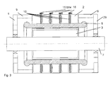
- the first four figures show an embodiment of an inventive cooling system for a rotating electrical machine highest power density, with fluid cooling and a closed coolant circuit in the stator 1, which here consists of five connected to tie rods spaced SterteilerteilblechMultien 2. Between SterteilblechMultien 2 is ever a cooling plate assembly 10 (here in the example, therefore, a total of four in this rotary electric machine) arranged as out FIG. 3 seen.
- FIG. 4 shows how the distribution of coolant supply and coolant removal takes place. Coolant supply takes place on one side of the machine via a central coolant main inlet 35 into a downstream coolant main distributor 33.
- stator cooling connection tubes 17 are connected to these main coolant distributor 33 arranged on the stator core 2, each of which is formed so long that it is in each case connected to a stator connecting piece makes the inlet 15 of a cooling plate assembly 10.
- the coolant is both radially distributed and guided inwardly, guided deflected outwards and leaves thedeteilblechune 10 via the stator connection piece for the expiry 16.
- the coolant removal of the heated coolant is carried out from thedeteilblechp 10 via individual another stator cooling connection pipes 17, which are connected to a coolant main collector 34 on the other opposite machine side. From this coolant main collector 34, the heated cooling medium is discharged via the coolant main drain 36.
- FIG. 2 shows twodekarleitbleche for the interior of adeteilblechps 10 with two identically formed against each other twisted and offset layereddekarleitblechen 13, which have a with the stator core 2 identical contour in the groove and tooth area.
- An analogue version shows FIG. 5 , where the interior of adeteilblechp 10 is shown for the rotor 3 of an induction machine.
- a constriction to form a volume flow symmetry 23 is arranged in the direction of the short distance to the stator connection piece for the outlet 15, so that a radial heat dissipation is possible radially and no thermal asymmetries arise.
- This bottleneck to the volume flow symmetry 23 may be omitted if, in a special case, the stator connection piece for the outlet 16 is arranged exactly opposite the stander connection piece for the inlet 15 offset by 180 degrees. Then the coolant flow would divide exactly halfway. However, this is relatively complicated in the production of the entire machine, which is why this special case production-wise rather no significance.
- In theisseratorieaubleblechen 13 here are the holes for the introduction of the tie rods 32 can be seen.
- the section AA again shows a cross section through four cooling part plates 11 (two boundary plates 12 and twodeffenleitbleche 13) in an assembled form as a cutout at the point where the cooling liquid from onedeleitblech 13 to the other cooling baffle 13 can flow through.
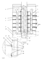
- FIG. 6 shows an induction machine with a cooling system according to the invention withdeteilblech Distribuen 10 both in the stator 1 and in the rotor 3.
- the supply of the cooling medium takes place here via axial rotor cooling connection pipes 18, which are fastened by means of screw soldering or welding connections in each case to a cooling medium part laminated core 10.
- Thedeatorileitbleche 13 have connection holes which are smaller than the recesses for the axial rotor cooling connection tubes 18 in the rotor lamination 3.
- a simple sheet metal section for the rotor core 4 is proposed, which in turn consists of two cover plates and two identicaldeffenleitblechen 13. Once set, solidification is again achieved by screwing, gluing, soldering, welding or pressing. It is also possible here to provide additional seals with between to ensure the fluid tightness permanently over the entire life of such a machine.
- a rotor cooling connection pipe 18 may also be arranged per cooling part laminated core 13 in the rotor. In FIG.
- each individual fluid-tight cooling part laminated core 10 is separately supplied with a rotor cooling connection pipe 18 with the cool cooling fluid, that is, six rotor cooling connection tubes 18 are formed for cooling fluid supply. These are usually arranged in a circular ring on a certain radius distributed radially in the rotor 3. It is z. B. the uppermostdeteilblechp 10 of the rotor 3 directly by means of a hollow screw 22, coupled via an expandable coupling and connecting piece 28 to the rotor connection element 21 and is acted upon via the rotor hollow shaft channel 20 and the rotor cooling channel 19 with cooling fluid.
- the rotor connection element 21 is likewise connected to the rotor cooling channel 19 via a hollow screw 22.
- the other five rotor cooling connection pipes 18 are formed radially distributed for cooling fluid discharge, which are coupled to the cooling plate assembly 10 via a hollow screw 22, thereby guided by the other rotor sub-packages or Läuferteilblechonge 4 and on the other hand via a cranked rotor connection element 21 via a inwardly directed rotor cooling channel 19 connected to the space around the siphon tube 27 and via the rotary leadthrough 26 to the rotor coolant main drain 37.
- the heated cooling fluid from the respective fluid-tightdeteilblechMultien 10 is again derived directly and performed on a direct path to the outside.
- the rotor hollow shaft channel 20 is arranged so that through this the cooling liquid via the at the rotary feedthrough 26th attached rotor coolant main supply 38 is supplied.
- the rotor fluid passes through a hollow screw 22 in the bent rotor connection element 21 via the rotor cooling duct 19 leading radially outwards through the rotor shaft.
- This rotor connection element 21 is connected to the rotor cooling connection pipe 18 by means of an expandable coupling and connection piece 28, which transfers the cooling liquid into the individual cooling part sheet packages 10 of the rotor 3 distributed over other special connecting and feeding elements.
- the cooling fluid now flows through thedeteilblechwovene 10 radially arcuately in both directions and is discharged via the oppositely disposed second rotor cooling connection tube 18 again.
- This in turn is connected to alldeteilblechmultien 10 of the rotor 3 at the appropriate locations.
- a series circuit of thedeteilblechwovene 10 is formed in the sheets of the rotor part package or Läufererteilblechongs 4 special recesses 24 for the rotor cooling connection pipes 18 are provided.
- the heated cooling medium is then passed via a radially inwardly leading rotor cooling channel 19, which opens into the space around the siphon tube 27, to the rotary feedthrough 26, on which the rotor coolant main drain 37 is arranged.
- the siphon tube 27 is guided through a rotary feedthrough 26 via which the coolant flows. Through the siphon tube 27 a safe separation ofchenzu- and coolant outlet is achieved.
- FIG. 1 shows fivedeteilbleche 11 in a preferred embodiment, of which two boundary plates 12 and threedeffenleitbleche for optimally cooling technology acting cooling plate assembly 10 for a stand 1.
- a special Axialleitblech 39 is arranged.
- This Axialleitblech 39 corresponds in shape exactly the sheet shape of the individual sheets of St Serteilblechpers 2 and causes primarily an axial flow guidance of the coolant inside theméteilblechpers 10.
- cooling system for a rotary electric machine highest power density, with fluid cooling in a closed coolant circuit in the stator and / or rotor, consisting of two or more interconnected partial laminated cores and wherein the partial laminated cores are spaced from each other and the runner from either solid part bodies or consists of laminated rotor laminations, there is a very effective cooling of electromagnetically active areas, ie the heat is dissipated directly in the immediate vicinity of the place of origin, without as sunday otherwise possible heat transfer over longer distances or several different materials must be made.
- FIG. 7 a cooling part plate 11 is shown, which is designed as a boundary plate 12.
- the two sealing grooves 44 are incorporated as circumferential grooves in the sheet material.
- the inner sealing groove 45 and also the outer sealing groove 46 can be produced for example by milling or electrical erosion.
- a continuous 0-ring made of rubber or another suitable sealing material, such as Viton is inserted into each sealing groove 44.
- FIG. 8 forms an assembly drawing of four individual superimposed, superimposed cooling part plates 11, which are connected to a cooling plate assembly 10 with each other.
- adeteilblechp 10 consisting of an internally arrangeddeatorileitblech 13 without Dichtungsnuten 44, an internally arrangeddekarleitblech 13 with two sealing grooves 44 and two outer boundary plates 12, each with an inner seal groove 45 and an outer seal groove 46 shown.
- the location and arrangement of the sealing grooves within a cooling plate assembly 10 is shown schematically.
Applications Claiming Priority (2)
| Application Number | Priority Date | Filing Date | Title |
|---|---|---|---|
| DE102010061113 | 2010-12-08 | ||
| DE102011056007A DE102011056007A1 (de) | 2010-12-08 | 2011-12-02 | Kühlsystem für eine rotierende elektrische Maschine höchster Leistungsdichte |
Publications (2)
| Publication Number | Publication Date |
|---|---|
| EP2463991A2 true EP2463991A2 (fr) | 2012-06-13 |
| EP2463991A3 EP2463991A3 (fr) | 2016-08-17 |
Family
ID=45218436
Family Applications (1)
| Application Number | Title | Priority Date | Filing Date |
|---|---|---|---|
| EP11192674.7A Pending EP2463991A3 (fr) | 2010-12-08 | 2011-12-08 | Système de refroidissement pour une machine électrique rotative à puissance maximale |
Country Status (2)
| Country | Link |
|---|---|
| EP (1) | EP2463991A3 (fr) |
| DE (1) | DE102011056007A1 (fr) |
Cited By (18)
| Publication number | Priority date | Publication date | Assignee | Title |
|---|---|---|---|---|
| US20140015347A1 (en) * | 2012-07-13 | 2014-01-16 | Lcdrives Corp. | Liquid cooled high efficiency permanent magnet machine with in slot glycol cooling |
| US20140015351A1 (en) * | 2012-07-13 | 2014-01-16 | Lcdrives Corp. | Liquid cooled high efficiency permanent magnet machine with glycol cooling |
| WO2014011511A3 (fr) * | 2012-07-13 | 2015-07-23 | Russel Marvin | Machine à aimant permanent à haut rendement refroidie par du glycol |
| WO2016107626A3 (fr) * | 2014-12-30 | 2016-09-09 | Vestas Wind Systems A/S | Refroidissement intégral par fluide de machine électrique |
| EP3157138A1 (fr) * | 2015-10-12 | 2017-04-19 | Siemens Aktiengesellschaft | Procede de refroidissement d'un paquet de toles, paquet de toles, rotor, stator et machine electrique |
| CN106849509A (zh) * | 2017-04-25 | 2017-06-13 | 沈阳工程学院 | 一种超高速永磁电机空心转子冷却结构 |
| DE102015225589A1 (de) | 2015-12-17 | 2017-06-22 | Volkswagen Aktiengesellschaft | Kühleinrichtung |
| US20180054094A1 (en) * | 2016-08-17 | 2018-02-22 | Atieva, Inc. | Motor Cooling System Utilizing Axial Cooling Channels |
| CN108768011A (zh) * | 2018-05-02 | 2018-11-06 | 浙江大学 | 一种电机定子冷却结构 |
| US10128701B2 (en) | 2016-08-17 | 2018-11-13 | Atieva, Inc. | Motor cooling system utilizing axial cooling channels |
| US10158263B2 (en) | 2016-08-17 | 2018-12-18 | Atieva, Inc. | Motor cooling system utilizing axial cooling channels |
| US10903701B2 (en) | 2016-08-17 | 2021-01-26 | Atieva, Inc. | Motor cooling system utilizing axial cooling channels |
| US10965192B2 (en) | 2019-04-12 | 2021-03-30 | Caterpillar Inc. | Cooling system for a rotary electric machine |
| US20220209594A1 (en) * | 2020-12-30 | 2022-06-30 | Volvo Car Corporation | Stator cooling for electric machines |
| US20220231551A1 (en) * | 2021-01-21 | 2022-07-21 | General Electric Company | Electric machine |
| US11462958B2 (en) | 2020-05-11 | 2022-10-04 | Atieva, Inc. | Stator-integrated manifold assembly to supply coolant to axial coolant channels |
| US11462957B2 (en) | 2020-05-11 | 2022-10-04 | Atieva, Inc. | Motor cooling system utilizing axial coolant channels |
| US11535097B2 (en) | 2020-05-11 | 2022-12-27 | Atieva, Inc. | Motor cooling system utilizing axial coolant channels |
Families Citing this family (3)
| Publication number | Priority date | Publication date | Assignee | Title |
|---|---|---|---|---|
| DE102017222635A1 (de) | 2017-12-13 | 2019-06-13 | Volkswagen Aktiengesellschaft | Stator und Elektromaschine mit Kühlsystem |
| DE102021130471B4 (de) | 2021-11-22 | 2023-07-20 | Dr. Ing. H.C. F. Porsche Aktiengesellschaft | Elektrische Maschine und Verfahren zum Betreiben derselben |
| DE102022109800A1 (de) | 2022-04-22 | 2023-10-26 | Dr. Ing. H.C. F. Porsche Aktiengesellschaft | Stator einer elektrischen Maschine und elektrische Maschine |
Citations (9)
| Publication number | Priority date | Publication date | Assignee | Title |
|---|---|---|---|---|
| DE1463926A1 (de) | 1963-07-12 | 1969-06-12 | Licentia Gmbh | Anordnung zur Kuehlung des Staenderblechpaketes grosser elektrischer Maschinen,insbesondere Turbogeneratoren,mit direkter Kuehlung der Wicklungsleiter |
| DE2917717C2 (fr) | 1979-05-02 | 1987-08-20 | Kraftwerk Union Ag, 4330 Muelheim, De | |
| DE9107197U1 (fr) | 1991-06-11 | 1992-10-15 | Siemens Ag, 8000 Muenchen, De | |
| DE9112631U1 (fr) | 1991-10-10 | 1993-02-04 | Siemens Ag, 8000 Muenchen, De | |
| DE4229395A1 (de) | 1992-09-03 | 1994-03-10 | Licentia Gmbh | Oberflächengekühlte, geschlossene elektrische Maschine |
| DE19651559A1 (de) | 1995-12-12 | 1997-06-19 | Gen Motors Corp | Adaptive Motorsteuerung |
| DE29714614U1 (de) | 1996-11-28 | 1997-10-30 | Siemens Ag | Elektrische Maschine mit Flüssigkeitskühlung |
| DE19917420A1 (de) | 1999-04-18 | 2000-10-19 | Elbtalwerk Gmbh | Anordnung und Verfahren zum Herstellen der Kühlkanäle drehender elektrischer Maschinen |
| DE102006049188B3 (de) | 2006-10-14 | 2008-03-27 | Antriebstechnik Katt Hessen Gmbh | Kühlsystem für hochausgenutzte elektrische Maschinen |
Family Cites Families (3)
| Publication number | Priority date | Publication date | Assignee | Title |
|---|---|---|---|---|
| CH89750A (fr) * | 1918-07-02 | 1921-07-01 | Joseph Shepherd | Stator à refroidissement par liquide pour machines dynamo-électriques. |
| SE318939B (fr) * | 1965-03-17 | 1969-12-22 | Asea Ab | |
| EP0824287A1 (fr) * | 1996-08-12 | 1998-02-18 | Siemens Aktiengesellschaft | Machine électrique avec rotor interne refroidi par liquide |
-
2011
- 2011-12-02 DE DE102011056007A patent/DE102011056007A1/de active Pending
- 2011-12-08 EP EP11192674.7A patent/EP2463991A3/fr active Pending
Patent Citations (9)
| Publication number | Priority date | Publication date | Assignee | Title |
|---|---|---|---|---|
| DE1463926A1 (de) | 1963-07-12 | 1969-06-12 | Licentia Gmbh | Anordnung zur Kuehlung des Staenderblechpaketes grosser elektrischer Maschinen,insbesondere Turbogeneratoren,mit direkter Kuehlung der Wicklungsleiter |
| DE2917717C2 (fr) | 1979-05-02 | 1987-08-20 | Kraftwerk Union Ag, 4330 Muelheim, De | |
| DE9107197U1 (fr) | 1991-06-11 | 1992-10-15 | Siemens Ag, 8000 Muenchen, De | |
| DE9112631U1 (fr) | 1991-10-10 | 1993-02-04 | Siemens Ag, 8000 Muenchen, De | |
| DE4229395A1 (de) | 1992-09-03 | 1994-03-10 | Licentia Gmbh | Oberflächengekühlte, geschlossene elektrische Maschine |
| DE19651559A1 (de) | 1995-12-12 | 1997-06-19 | Gen Motors Corp | Adaptive Motorsteuerung |
| DE29714614U1 (de) | 1996-11-28 | 1997-10-30 | Siemens Ag | Elektrische Maschine mit Flüssigkeitskühlung |
| DE19917420A1 (de) | 1999-04-18 | 2000-10-19 | Elbtalwerk Gmbh | Anordnung und Verfahren zum Herstellen der Kühlkanäle drehender elektrischer Maschinen |
| DE102006049188B3 (de) | 2006-10-14 | 2008-03-27 | Antriebstechnik Katt Hessen Gmbh | Kühlsystem für hochausgenutzte elektrische Maschinen |
Cited By (26)
| Publication number | Priority date | Publication date | Assignee | Title |
|---|---|---|---|---|
| US20140015347A1 (en) * | 2012-07-13 | 2014-01-16 | Lcdrives Corp. | Liquid cooled high efficiency permanent magnet machine with in slot glycol cooling |
| US20140015351A1 (en) * | 2012-07-13 | 2014-01-16 | Lcdrives Corp. | Liquid cooled high efficiency permanent magnet machine with glycol cooling |
| WO2014011511A3 (fr) * | 2012-07-13 | 2015-07-23 | Russel Marvin | Machine à aimant permanent à haut rendement refroidie par du glycol |
| US10348146B2 (en) * | 2012-07-13 | 2019-07-09 | Lcdrives Corp. | Liquid cooled high efficiency permanent magnet machine with glycol cooling |
| US10312760B2 (en) * | 2012-07-13 | 2019-06-04 | Lcdrives Corp. | Liquid cooled high efficiency permanent magnet machine with in slot glycol cooling |
| WO2016107626A3 (fr) * | 2014-12-30 | 2016-09-09 | Vestas Wind Systems A/S | Refroidissement intégral par fluide de machine électrique |
| US11355976B2 (en) | 2014-12-30 | 2022-06-07 | Vestas Wind Systems A/S | Integral fluid cooling of electrical machine |
| US20180013326A1 (en) * | 2014-12-30 | 2018-01-11 | Vestas Wind Systems A/S | Integral fluid cooling of electrical machine |
| EP3157138A1 (fr) * | 2015-10-12 | 2017-04-19 | Siemens Aktiengesellschaft | Procede de refroidissement d'un paquet de toles, paquet de toles, rotor, stator et machine electrique |
| CN106849414A (zh) * | 2015-10-12 | 2017-06-13 | 西门子公司 | 用于冷却叠片组的方法、叠片组、转子、定子和电机 |
| CN106849414B (zh) * | 2015-10-12 | 2019-08-23 | 西门子公司 | 用于冷却叠片组的方法、叠片组、转子、定子和电机 |
| DE102015225589A1 (de) | 2015-12-17 | 2017-06-22 | Volkswagen Aktiengesellschaft | Kühleinrichtung |
| US10158263B2 (en) | 2016-08-17 | 2018-12-18 | Atieva, Inc. | Motor cooling system utilizing axial cooling channels |
| US10128701B2 (en) | 2016-08-17 | 2018-11-13 | Atieva, Inc. | Motor cooling system utilizing axial cooling channels |
| US20180054094A1 (en) * | 2016-08-17 | 2018-02-22 | Atieva, Inc. | Motor Cooling System Utilizing Axial Cooling Channels |
| US10903701B2 (en) | 2016-08-17 | 2021-01-26 | Atieva, Inc. | Motor cooling system utilizing axial cooling channels |
| CN106849509A (zh) * | 2017-04-25 | 2017-06-13 | 沈阳工程学院 | 一种超高速永磁电机空心转子冷却结构 |
| CN108768011A (zh) * | 2018-05-02 | 2018-11-06 | 浙江大学 | 一种电机定子冷却结构 |
| CN108768011B (zh) * | 2018-05-02 | 2024-04-05 | 浙江大学 | 一种电机定子冷却结构 |
| US10965192B2 (en) | 2019-04-12 | 2021-03-30 | Caterpillar Inc. | Cooling system for a rotary electric machine |
| US11462957B2 (en) | 2020-05-11 | 2022-10-04 | Atieva, Inc. | Motor cooling system utilizing axial coolant channels |
| US11462958B2 (en) | 2020-05-11 | 2022-10-04 | Atieva, Inc. | Stator-integrated manifold assembly to supply coolant to axial coolant channels |
| US11535097B2 (en) | 2020-05-11 | 2022-12-27 | Atieva, Inc. | Motor cooling system utilizing axial coolant channels |
| US20220209594A1 (en) * | 2020-12-30 | 2022-06-30 | Volvo Car Corporation | Stator cooling for electric machines |
| US20220231551A1 (en) * | 2021-01-21 | 2022-07-21 | General Electric Company | Electric machine |
| US11962188B2 (en) * | 2021-01-21 | 2024-04-16 | General Electric Company | Electric machine |
Also Published As
| Publication number | Publication date |
|---|---|
| DE102011056007A1 (de) | 2012-06-14 |
| EP2463991A3 (fr) | 2016-08-17 |
Similar Documents
| Publication | Publication Date | Title |
|---|---|---|
| EP2463991A2 (fr) | Système de refroidissement pour une machine électrique rotative à puissance maximale | |
| DE102005002897B4 (de) | Flüssigkeitsgekühlte elektrische Maschine mit Gussgehäuse | |
| DE102004022557B4 (de) | Elektrische Maschine mit Wasserkühlung | |
| EP2645544B1 (fr) | Machine électrique dotée d'un refroidissement interne efficace | |
| DE19749108C1 (de) | Elektromotor | |
| EP0858692B1 (fr) | Systeme de refroidissement a liquide pour moteurs electriques | |
| WO2006106086A1 (fr) | Machine electrique a enveloppe de refroidissement par liquide | |
| WO2012031921A2 (fr) | Boîtier de réception d'un entraînement électrique | |
| WO2018211089A1 (fr) | Machine électrique, en particulier pour véhicule | |
| DE102011076904A1 (de) | Gekühlter Stator für Elektromotor | |
| DE102016225342A1 (de) | Gehäuse einer elektrischen Maschine, Statoranordnung einer elektrischen Maschine sowie elektrische Maschine | |
| EP2479875B1 (fr) | Boîtier à liquide refroidi doté d'une flasque pour machine électrique | |
| EP2680408A1 (fr) | Châssis doté d'un refroidissement intégré pour un entraînement électrique | |
| WO2018211086A1 (fr) | Machine électrique, en particulier pour véhicule | |
| WO2020216507A1 (fr) | Machine électrique à support de couple dans le carter | |
| AT505153B1 (de) | Schienenfahrzeug-direktantrieb sowie verfahren zu seiner herstellung | |
| DE102014221204B4 (de) | Hybridmodul sowie Herstellungsverfahren eines Hybridmoduls für ein Fahrzeug | |
| WO2019110271A1 (fr) | Machine électrique, en particulier pour un véhicule | |
| WO2018211088A1 (fr) | Machine électrique, en particulier pour véhicule | |
| DE19851439A1 (de) | Elektrische Maschine mit Kühlung | |
| EP2507897A2 (fr) | Corps coulé à double paroi pour un moteur électrique refroidi par liquide | |
| EP1519468A2 (fr) | Machine électrique à refroidissement fluidique et méthode de fabrication d'une telle machine | |
| EP3324521B1 (fr) | Plaque de refroidissement pour moteur linéaire | |
| DE2016261B2 (de) | Gasgekühlte dynamoelektrische Maschine großer Leistung | |
| WO2020216508A1 (fr) | Machine électrique dotée d'un corps en matière plastique |
Legal Events
| Date | Code | Title | Description |
|---|---|---|---|
| PUAI | Public reference made under article 153(3) epc to a published international application that has entered the european phase |
Free format text: ORIGINAL CODE: 0009012 |
|
| AK | Designated contracting states |
Kind code of ref document: A2 Designated state(s): AL AT BE BG CH CY CZ DE DK EE ES FI FR GB GR HR HU IE IS IT LI LT LU LV MC MK MT NL NO PL PT RO RS SE SI SK SM TR |
|
| AX | Request for extension of the european patent |
Extension state: BA ME |
|
| RBV | Designated contracting states (corrected) |
Designated state(s): AL AT BE BG CH CY CZ DE DK EE ES FI FR GB GR HR HU IE IS IT LI LT LU LV MC MK MT NL NO PL PT RO RS SE SI SK SM TR |
|
| PUAL | Search report despatched |
Free format text: ORIGINAL CODE: 0009013 |
|
| AK | Designated contracting states |
Kind code of ref document: A3 Designated state(s): AL AT BE BG CH CY CZ DE DK EE ES FI FR GB GR HR HU IE IS IT LI LT LU LV MC MK MT NL NO PL PT RO RS SE SI SK SM TR |
|
| AX | Request for extension of the european patent |
Extension state: BA ME |
|
| RIC1 | Information provided on ipc code assigned before grant |
Ipc: H02K 1/32 20060101ALI20160708BHEP Ipc: H02K 1/20 20060101ALI20160708BHEP Ipc: H02K 9/19 20060101AFI20160708BHEP |
|
| STAA | Information on the status of an ep patent application or granted ep patent |
Free format text: STATUS: REQUEST FOR EXAMINATION WAS MADE |
|
| 17P | Request for examination filed |
Effective date: 20170214 |
|
| STAA | Information on the status of an ep patent application or granted ep patent |
Free format text: STATUS: EXAMINATION IS IN PROGRESS |
|
| 17Q | First examination report despatched |
Effective date: 20200226 |
|
| STAA | Information on the status of an ep patent application or granted ep patent |
Free format text: STATUS: EXAMINATION IS IN PROGRESS |
|
| STAA | Information on the status of an ep patent application or granted ep patent |
Free format text: STATUS: EXAMINATION IS IN PROGRESS |