EP2463980A2 - Fonctionnement d'un générateur d'énergie dans un réseau d'alimentation en énergie - Google Patents
Fonctionnement d'un générateur d'énergie dans un réseau d'alimentation en énergie Download PDFInfo
- Publication number
- EP2463980A2 EP2463980A2 EP11009760A EP11009760A EP2463980A2 EP 2463980 A2 EP2463980 A2 EP 2463980A2 EP 11009760 A EP11009760 A EP 11009760A EP 11009760 A EP11009760 A EP 11009760A EP 2463980 A2 EP2463980 A2 EP 2463980A2
- Authority
- EP
- European Patent Office
- Prior art keywords
- voltage
- reactive power
- power
- energy
- generator
- Prior art date
- Legal status (The legal status is an assumption and is not a legal conclusion. Google has not performed a legal analysis and makes no representation as to the accuracy of the status listed.)
- Granted
Links
- 238000000034 method Methods 0.000 claims abstract description 9
- 230000007704 transition Effects 0.000 claims description 11
- 238000012384 transportation and delivery Methods 0.000 claims description 11
- 238000004146 energy storage Methods 0.000 claims description 7
- 230000006641 stabilisation Effects 0.000 claims description 3
- 238000011105 stabilization Methods 0.000 claims description 3
- 230000001131 transforming effect Effects 0.000 abstract description 2
- 230000001172 regenerating effect Effects 0.000 description 7
- 238000007726 management method Methods 0.000 description 5
- 238000012423 maintenance Methods 0.000 description 4
- 241000196324 Embryophyta Species 0.000 description 3
- 238000005259 measurement Methods 0.000 description 3
- 238000010586 diagram Methods 0.000 description 2
- 230000005611 electricity Effects 0.000 description 2
- 230000005284 excitation Effects 0.000 description 2
- 239000000725 suspension Substances 0.000 description 2
- 241001236093 Bulbophyllum maximum Species 0.000 description 1
- 241000772415 Neovison vison Species 0.000 description 1
- 238000004378 air conditioning Methods 0.000 description 1
- 238000013459 approach Methods 0.000 description 1
- 230000005540 biological transmission Effects 0.000 description 1
- 238000004364 calculation method Methods 0.000 description 1
- 238000006243 chemical reaction Methods 0.000 description 1
- 239000003245 coal Substances 0.000 description 1
- 230000006378 damage Effects 0.000 description 1
- 230000007547 defect Effects 0.000 description 1
- 238000012544 monitoring process Methods 0.000 description 1
- 230000005855 radiation Effects 0.000 description 1
- 230000001105 regulatory effect Effects 0.000 description 1
- 239000004065 semiconductor Substances 0.000 description 1
- 238000012358 sourcing Methods 0.000 description 1
- 230000001360 synchronised effect Effects 0.000 description 1
Images

Classifications
-
- H—ELECTRICITY
- H02—GENERATION; CONVERSION OR DISTRIBUTION OF ELECTRIC POWER
- H02J—CIRCUIT ARRANGEMENTS OR SYSTEMS FOR SUPPLYING OR DISTRIBUTING ELECTRIC POWER; SYSTEMS FOR STORING ELECTRIC ENERGY
- H02J3/00—Circuit arrangements for ac mains or ac distribution networks
- H02J3/12—Circuit arrangements for ac mains or ac distribution networks for adjusting voltage in ac networks by changing a characteristic of the network load
- H02J3/16—Circuit arrangements for ac mains or ac distribution networks for adjusting voltage in ac networks by changing a characteristic of the network load by adjustment of reactive power
-
- H—ELECTRICITY
- H02—GENERATION; CONVERSION OR DISTRIBUTION OF ELECTRIC POWER
- H02J—CIRCUIT ARRANGEMENTS OR SYSTEMS FOR SUPPLYING OR DISTRIBUTING ELECTRIC POWER; SYSTEMS FOR STORING ELECTRIC ENERGY
- H02J3/00—Circuit arrangements for ac mains or ac distribution networks
- H02J3/38—Arrangements for parallely feeding a single network by two or more generators, converters or transformers
- H02J3/381—Dispersed generators
-
- H—ELECTRICITY
- H02—GENERATION; CONVERSION OR DISTRIBUTION OF ELECTRIC POWER
- H02J—CIRCUIT ARRANGEMENTS OR SYSTEMS FOR SUPPLYING OR DISTRIBUTING ELECTRIC POWER; SYSTEMS FOR STORING ELECTRIC ENERGY
- H02J2300/00—Systems for supplying or distributing electric power characterised by decentralized, dispersed, or local generation
- H02J2300/20—The dispersed energy generation being of renewable origin
- H02J2300/22—The renewable source being solar energy
- H02J2300/24—The renewable source being solar energy of photovoltaic origin
-
- H—ELECTRICITY
- H02—GENERATION; CONVERSION OR DISTRIBUTION OF ELECTRIC POWER
- H02J—CIRCUIT ARRANGEMENTS OR SYSTEMS FOR SUPPLYING OR DISTRIBUTING ELECTRIC POWER; SYSTEMS FOR STORING ELECTRIC ENERGY
- H02J2300/00—Systems for supplying or distributing electric power characterised by decentralized, dispersed, or local generation
- H02J2300/20—The dispersed energy generation being of renewable origin
- H02J2300/28—The renewable source being wind energy
-
- Y—GENERAL TAGGING OF NEW TECHNOLOGICAL DEVELOPMENTS; GENERAL TAGGING OF CROSS-SECTIONAL TECHNOLOGIES SPANNING OVER SEVERAL SECTIONS OF THE IPC; TECHNICAL SUBJECTS COVERED BY FORMER USPC CROSS-REFERENCE ART COLLECTIONS [XRACs] AND DIGESTS
- Y02—TECHNOLOGIES OR APPLICATIONS FOR MITIGATION OR ADAPTATION AGAINST CLIMATE CHANGE
- Y02E—REDUCTION OF GREENHOUSE GAS [GHG] EMISSIONS, RELATED TO ENERGY GENERATION, TRANSMISSION OR DISTRIBUTION
- Y02E10/00—Energy generation through renewable energy sources
- Y02E10/50—Photovoltaic [PV] energy
- Y02E10/56—Power conversion systems, e.g. maximum power point trackers
-
- Y—GENERAL TAGGING OF NEW TECHNOLOGICAL DEVELOPMENTS; GENERAL TAGGING OF CROSS-SECTIONAL TECHNOLOGIES SPANNING OVER SEVERAL SECTIONS OF THE IPC; TECHNICAL SUBJECTS COVERED BY FORMER USPC CROSS-REFERENCE ART COLLECTIONS [XRACs] AND DIGESTS
- Y02—TECHNOLOGIES OR APPLICATIONS FOR MITIGATION OR ADAPTATION AGAINST CLIMATE CHANGE
- Y02E—REDUCTION OF GREENHOUSE GAS [GHG] EMISSIONS, RELATED TO ENERGY GENERATION, TRANSMISSION OR DISTRIBUTION
- Y02E10/00—Energy generation through renewable energy sources
- Y02E10/70—Wind energy
- Y02E10/76—Power conversion electric or electronic aspects
-
- Y—GENERAL TAGGING OF NEW TECHNOLOGICAL DEVELOPMENTS; GENERAL TAGGING OF CROSS-SECTIONAL TECHNOLOGIES SPANNING OVER SEVERAL SECTIONS OF THE IPC; TECHNICAL SUBJECTS COVERED BY FORMER USPC CROSS-REFERENCE ART COLLECTIONS [XRACs] AND DIGESTS
- Y02—TECHNOLOGIES OR APPLICATIONS FOR MITIGATION OR ADAPTATION AGAINST CLIMATE CHANGE
- Y02E—REDUCTION OF GREENHOUSE GAS [GHG] EMISSIONS, RELATED TO ENERGY GENERATION, TRANSMISSION OR DISTRIBUTION
- Y02E40/00—Technologies for an efficient electrical power generation, transmission or distribution
- Y02E40/30—Reactive power compensation
Definitions
- the invention relates to a method and a device for operating at least one energy generator, which is designed in particular as a regenerative energy generator, in a power supply network with voltage levels connected via a first and a second transformer.
- the different levels of voltage are, for. B. by three contiguous voltage levels whose upper two voltage levels are connected to each other via a first transformer and the lower two voltage levels via the second transformer.
- the energy suppliers or network operators more or less narrow limits for the power and voltage quality in terms of the reactive power component (reactive power supply or reactive power delivery) of the electricity supplier and the power consumers, represented by the cos phi value in the phasor diagram of current and voltage set.
- the permissible value of cos phi for a non-reactive power purchase or a reactive power feed-in is 0.95.
- This limit serves to stabilize the networks in order to avoid overvoltage, which can lead to the destruction of connected loads, and undervoltage, which can lead to consumer failure.
- the price serves as a regulator for compliance with the set cos phi values.
- a feed-in or a purchase of reactive power outside of the bandwidth prescribed by the utility or main network operator for the cos phi is subject to significant penalties or additional payments.
- Each photovoltaic system (PV system) generates a direct current, which is converted by means of an inverter into an alternating current and fed under suitable conditions into a power supply network.
- inverters can both electronic devices as well as electromechanical converters are used. Inverters are to be understood as meaning all devices which can generate an AC voltage from a DC voltage. Although wind turbines generate directly an alternating current. However, this is to be adapted via a frequency converter to the conditions of the public supply network (power supply network). These frequency converters also include inverters and should be included as means.
- the electronic components of an inverter allow setting a desired cos phi value in relation to the power. For most PV systems, this is done by a cos phi pointer, which can be used to set a fixed ratio of injected power to injected or referenced reactive power. So the control unit z. For example, it is required to set any power fed into the grid at a cos phi of 0.97.
- an inverter for a photovoltaic system by means of which a solar system can be connected to a power grid and having a control unit for the dynamic calculation of a compensation current to compensate for harmonics and reactive power in the network.
- the control unit calculates a compensation current setpoint based on a measured mains voltage value.
- the measuring element of the mains voltage measurement is arranged at the connection point at which the inverter feeds the energy into the network.
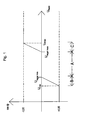
- the cos phi value is not necessarily fixed, but can be used in accordance with a diagram according to the Fig. 1 be set dynamically depending on the current needs.
- a cos phi value to be set is plotted on the output of the inverter via the mains voltage.
- the output voltage (U network ) for feeding into the grid may only vary within a range between a minimum value (U min ) and a maximum value U max . Outside of this area of supply to the grid approved by the utility with a cos phi of z. B. maximum 0.95, the PV system should not be operated.
- energy suppliers in particular in their contractual relationship with the main grid operator (eg nuclear power station, coal power station, etc.) as an energy supplier, are contractually obliged not to exceed a reactive power reference value of cos phi 0.95 in order to ensure voltage stability in the supraregional main network.
- a cos phi value of 0.94 represents an overshoot of the reference
- a cos phi value of 0.96 represents a shortfall, ie a non-exploitation of the maximum permitted reference.
- sourcing or supplying reactive power is often required in the lower networks to compensate for a voltage increase from the input of solar and wind power, or to compensate for a voltage drop due to failed supply of alternatively generated energy or starting up of machinery.
- the output voltage can be increased at the transformer 19. This means for nearby towns A and K that they are supplied at the upper edge of the desired voltage bandwidth. For the remote locations, this means that they are more likely to be supplied at the bottom of the voltage bandwidth. If there is a larger photovoltaic system in the village K, then - as described above Fig. 1 - Their control device strive to lead the PV system back to the area B, since the system is operated due to the increased mains voltage in the range of the right flank, ie in the area.
- the invention is based on the object to make a contribution to increasing the supply stability in an electrical energy supply network.
- This object is achieved in that a reactive power transition between the two upper voltage levels detected on the first transformer and the voltage is determined at a first network connection point at the lowest voltage level.
- the level of a reactive power demand applied by a power generator of the power supply network is calculated as a function of the determined voltage value in order to keep the voltage determined on the lowest voltage level within a predefinable voltage range. Based on the calculated reactive power demand, a means of the power generator for a reactive power purchase or a reactive power delivery is driven.
- network connection point is usually the position of the counting point between the consumer and the network and between the feeder and the network understood. In the present case, furthermore, any position within the public supply network as well as the network of the consumers and the feeders at which the voltage measurement is carried out is understood.
- the invention comprises, in addition to the method, a device for operating at least one energy generator, which is configured in particular as a regenerative energy generator, in an electrical energy supply network having several voltage levels, whose two upper voltage levels are connected via a first transformer and whose two lower voltage levels are connected via a second transformer ,
- the power generator is connected to the lowest voltage level via a first network connection point or via another network connection point or to the middle voltage level via a second network connection point.
- a measuring device detects the reactive power transition between the two upper voltage levels on the first transformer.
- a voltmeter determines the voltage at a first grid connection point at the lowest voltage level.
- a computing device calculates the level of a reactive power demand operated by the energy generator as a function of the voltage value determined by the voltage measuring device, in order to keep the voltage determined on the lowest voltage level within a predefinable voltage range.
- a control and / or control unit (13) is provided and arranged to control a means of the power generator for a reactive power purchase or a reactive power delivery based on the calculated reactive power demand.
- the method and the device are used for the reactive power management of the supply level with the aim of a voltage as balanced as possible within the respective considered plane, in particular while maintaining a predefinable reactive power reference from the mains (upper voltage level).
- the funds essentially consist of an electronic or an electromechanical inverter. These devices have due to their inherent components such.
- an already existing ability of the devices is used for a further purpose, namely the stabilization of the supply network. This is usually done without sacrificing the delivery of active power.
- An inverter of z. B. 1 MW (MVA) rated power which is charged due to the current solar radiation with only 0.6 MVA, has a free capacity for the supply or purchase of reactive power in the amount of 0.4 MVAr.
- this inverter can thus under suspension of its usual control scheme after the FIG. 1 be operated with a capacitive cos phi according to a reactive power feed to contribute to the voltage boost. Usually it would be attempted to maintain the control range of the inverter by lowering the voltage.
- the operation of the inverter is maintained by its inherent control device to the maximum power point MPP of the photovoltaic system or the wind turbine.
- the inverter should feed or extract from the supply level such a reactive power quantity which corresponds at most to the difference between the currently supplied power and the nominal power of the inverter.
- the reactive power amount is limited to the power remaining to reach the rated power of the inverter, so that the energy generated by the power generator itself is not restricted or reduced.
- the free power capacity of the inverter is used only to fulfill another function, namely that of the phase shifter or reactive power supplier.
- the operation of the inverter provides, bypassing the required suspension of its inherent control device towards the maximum power point MPP feed a predetermined reactive power component in the supply level or to obtain from this. This is advantageous if the supply of reactive power to stabilize the network is more expedient for the plant operator due to the current network conditions, as active power for the drive of machinery or the operation of air conditioning systems, etc. provide.
- a particularly suitable place for the placement of the voltage measuring device is at the end of a stub or in relation to a mains transformer feeding a loop transformer in the middle of the loop or in the case of several feeding transformers in its vicinity.
- the most voltage-sensitive network connection point in particular under the hypothesis of a transformer failure, is selected. This can also be another place, if there z. B. a consumer is provided, the heavy machinery operates with high starting current, which are frequently turned on and off daily. Alternatively, the consumer with the highest variation in reactive power reference is determined while measuring the voltage value at the grid connection point of that consumer.
- the most stress-sensitive point is characterized by the highest voltage variation in relation to a feeding or related electrical power.
- the voltage variation may be defined by a percentage change amount and not by the absolute voltage values considered. This is in the presence of a loop often in the middle in relation to the transformer to the next higher network of the case, that is, at the point where there is the same distance from the transformer in both directions.
- the operating principle of the inverter is characterized by the fact that a measured undervoltage below a threshold leads to a supply of reactive power by the inverter. A threatening overvoltage, z. B. on reaching an upper threshold leads to a reference of reactive power through the at least one inverter.
- a more extensive monitoring of the voltage state on the power supply system mains system provides that the voltage at the network connection points is determined by several consumers at the same supply level, and that the operation management takes place on the basis of the correspondingly more voltage values.
- the reactive power component to be supplied is divided into the corresponding multiple inverters such that the inverters involved in total work as low as possible.
- the low-loss property should be understood in such a way that from the regenerative energy supply, eg. As sun or wind, the largest possible amount of kilowatt hours can be fed into the grid. This allows efficient utilization of the available reactive power capacities.
- the one power generator is preferably used for the reactive power supply or the reactive power reference, which is spatially adjacent to the network connection point at which the voltage value is determined and which approaches a critical value.
- the control device has a limiter which applies the predetermined reactive power amount in such a way that a maximum permissible voltage at the output of the inverter is not exceeded. It may also be appropriate, the Be able to provide the control device with the possibility of applying the predetermined reactive power amount in such a way that a minimum permissible voltage at the input of the inverter is not undershot.
- the controller suitably includes a control algorithm that keeps the reactive power transition below a predetermined threshold.
- an energy supplier is also an energy storage in question, which may consist of a battery bank. Also, a pumped storage power plant or the like is conceivable. On request, this energy store can then draw power or also reactive power from the relevant voltage level or feed it into the voltage level.
- the energy store or at least one of the energy suppliers supplies reactive power to the lowest voltage level, while at the same time another power generator or another energy storage device draws reactive power from the voltage level. This depends on the geographical proximity of the energy producer or supplier to the consumers. It is likewise expedient for the energy store or at least one of the energy producers to supply reactive power to one of the two lowest voltage levels, while at the same time another power generator or another energy store draws reactive power from one of the two voltage levels.
- a possible operational management can provide that, in the presence of a maximum permissible reactive power transition and a maximum possible reactive power delivery of the at least one energy supplier and optionally the envisaged energy storage and a voltage measured at the edge of the predetermined voltage range, a signal is generated which reduces the power of the energy supplier in favor of a reactive power delivery entails.
- the omission of power is here to be accepted in favor of a reactive power compensation.
- Fig. 1 is a control scheme of the cos phi about the inverter output voltage U shown, which is in principle advantageous in modern PV systems used and to facilitate the understanding of the subsequent description.
- U min and U max Two limit values U min and U max are provided which generally should not be undershot or exceeded. Between these marginal limits U min and U max is a linear control range A, which is limited by two control limits U rule min and U rule max . In this area A, the cos phi system is run neutrally and pure active power is fed into the supply network. If the operating point of the inverter with its output voltage U in the region B between U min and U rule min , so reactive power VAr (ampere reactive) is also supplied to the supply network.
- VAr ampere reactive
- an operating point of the inverter with an output voltage U in the range C between U max and U max rule is taken in addition to the power supply reactive power VAr the supply network.
- the operating point is over semiconductor elements or switches, in particular IGBT's (Insulated Gate Bipolar Transistor) in the inverter, in particular by means of a so-called MPP regulator (M aximum P ower P oint) is adjustable.
- IGBT's Insulated Gate Bipolar Transistor
- MPP regulator M aximum P ower P oint
- a reactive power reference from the grid which generally means a tendency to reduce the voltage of the grid voltage, or even a reactive power feed, which is synonymous with a voltage boost at the supply level to which the inverter is connected.
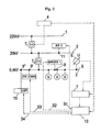
- FIG. 2 three voltage or supply levels 1, 2, 3 of an electrical power supply network are shown.
- Supply level 1 is a 220 kV high voltage level
- supply level 2 is a 20 kV medium voltage level
- supply level 3 is a 400 volt low voltage level.
- a first transformer T1 biases the high voltage down to the medium voltage.
- a second transformer T2 biases the medium voltage down to the low voltage.
- a measuring device 4 is connected, which detects the reactive power transition between the two upper voltage levels 1, 2 at the first transformer T1. The determined value of the reactive power transition is transmitted to a computing unit 7, will be discussed in more detail below.
- the goal of the reactive power management of the supply level 1 is, at this point, a specifiable cos phi limit, z. B. a cos phi of 0.95, not to fall below.
- the voltage prevailing at this point on the low-voltage level 3 is measured by means of a voltage measuring device 6.
- the corresponding measured value is forwarded to the computing device 7 via a signal line.
- Signal lines are shown with dashed lines, while energy flow lines are shown in solid lines.
- a first energy generator EE1 also referred to below as an energy supplier, is connected to the lowest voltage level 3 via another network connection point 9.
- the first power generator EE1 is a photovoltaic system (PV system) with an inverter WR transforming the generated direct current into an alternating current.
- the photovoltaic system can be an ordinary roof system, of which a plurality (shown is only a second energy supplier or energy producer EE2) are connected to the lowest voltage level 3 via a corresponding multiplicity of other network connection points 9 '.
- the first network connection point 5, to which the voltage measuring device 6 is connected can also be an entry point for one of the energy producers EE at the same time.
- a further energy generator or supplier EE3 can be connected to the middle voltage level 2 via a second network connection point 11, which is located on the middle voltage level 2. It is common to the energy generators EE1 to EE3 that they can serve a reactive power demand on demand or request. This means that the energy producers EE1 to EE3 are technically capable of delivering or receiving reactive power (VAr) via the connection point 9, 9 'to the relevant supply level 2, 3.
- the computing device 7 determines the amount of the reactive power requirement that is required in order to maintain the voltage determined on the lowest voltage level 3 within a predefinable voltage range as a function of the voltage value determined by the voltage measuring device 6. In this case, compliance with the maximum permissible value of the reactive power transition occurring at the first transformer T1 must be respected. For example, if the measured voltage U at the first grid connection point 5 is close to the lower limit of the predetermined voltage range, the power plane 3 is to be supplied with reactive power VAR to raise the voltage.
- reactive power VAr must be taken from the voltage plane.
- the size of the reactive power VAr to be drawn or taken is determined in the computing device 7 and forwarded to a control and control unit 13.
- This generates one or more output signals S1 to S3, which influences the responsible for the reactive power reference or the reactive power supply means of the energy generator EE1 to EE3.
- This means is in photovoltaic systems as an energy generator EE of this inherent inverter WR, which is able to generate or record reactive power VAr as part of its rated power via a corresponding control of the installed IGBT's. For mechanical inverters WR this is the setting of the excitation current of the participating machines.
- an energy store 15 is shown which can be provided at one of the voltage levels 1 to 3 via its own network connection point 9 "to draw reactive power VAr from the voltage level 3 or to feed it into the voltage level 3.
- the energy store 15 is at the lowest voltage level 3, which may also be provided at the middle voltage level 2.
- the energy store 15 also receives its control signal S4 from the control and regulating unit 13.
- the energy store 15 or at least one of the energy generators EE1 or EE2 has reactive power VAr into the lower voltage level 2, while at the same time another power generator EE3 or another energy storage device draws reactive power from another voltage level
- the energy storage 15 may be a per se known device, such as a battery bank, a pumped storage power plant or a combination of different types from Ene rgie appointmentn.
- a ring line 17 is shown on the medium-voltage level 2, to which a number of localities A to K are connected, in which the voltage is connected to the low-voltage level 3 via further transformers, of which only that of the locality D is shown and designated by reference numeral 18 is brought.
- the ring line 17 is supplied by the high voltage level 1 via two supply transformers 19 and 21 with electrical energy.
- the transformer 19 undergoes maintenance and is disconnected from the grid. This would mean that the fed from the remaining supply transformer 21 towns E and D only a voltage level at the lower end of the rated voltage of z. B. 20kV is available. As the lower end z. B. a value of 3% below the rated voltage, so in this case viewed from 19.4kV.
- the connection of a heavy machinery in the village F would therefore lead to a drop below the minimum voltage and a flickering of the lights in the villages E and D. This threatening condition is via a voltage meter 6, which is connected to a network connection point 5, via which the locality D is supplied with electrical energy.
- the network connection point 5 is in this case on the secondary or low-voltage side of the further transformer 18 of the locality D, ie on the 0.4 kV voltage level 3.
- the measured voltage value is fed to a computing device 7 which derives therefrom a value of reactive power supply for raising the voltage at the network connection point 5 calculated.
- This request is forwarded to a control and control unit 13, which forms therefrom a signal S, which is passed to at least one energy supplier EE.
- this is the largest photovoltaic system in the locality C, which is closest to the desired geographical point of the voltage boost, ie the locality D.
- the local photovoltaic system is then set by the control and control unit 13 so that currently not needed for solar energy conversion, so free power capacity of the inverter WR can be used to supply reactive power.
- the possible delivery contribution corresponds to the difference between the generated power P and the rated power of the inverter WR.
- the energy generator EE located there just feed its rated power into the grid so that no additional reactive power VAr can be fed in then it may be desirable to reduce the power P in favor of a reactive power supply.
- the one for reducing the power whose contribution to voltage stabilization is most effective should be made, that is, in the example shown, the photovoltaic system in the locality C.
- the most effective contribution to the energy producer EE is the one that lies at the most stress-sensitive point on the nearest or at the end of a stub or near the middle on a loop.
- the most stress sensitive point is defined by a percentage deviation in relation to the rated voltage of the considered supply level.
- the most stress-sensitive point depends on the conditions on site, ie which industrial plants are in which localities A to K and / or which cable cross-sections are laid, etc. In this case, this point is determined over a longer period of operation by observing the measured voltage values.
- a multiplicity of voltage measuring devices 6 can be present at different locations on the considered network level 2 and / or 3 in order to detect a voltage image of the entire network area and from this the amount the reactive power requirement and the most suitable power generator EE for reactive power delivery to determine. Not only can a reactive power supply be required to boost the voltage. Also, elsewhere in the mink as well as a reactive power reference to reduce the voltage may be useful.
- the voltage measuring device 6 is conveniently placed at the end of the stub, preferably at the network connection point of the last consumer, especially since there the lowest voltage is expected.
Applications Claiming Priority (1)
| Application Number | Priority Date | Filing Date | Title |
|---|---|---|---|
| DE102010054233A DE102010054233A1 (de) | 2010-12-11 | 2010-12-11 | Energieversorgungsnetz mit Blindleistungsmanagement |
Publications (3)
| Publication Number | Publication Date |
|---|---|
| EP2463980A2 true EP2463980A2 (fr) | 2012-06-13 |
| EP2463980A3 EP2463980A3 (fr) | 2014-05-21 |
| EP2463980B1 EP2463980B1 (fr) | 2018-11-28 |
Family
ID=45442753
Family Applications (1)
| Application Number | Title | Priority Date | Filing Date |
|---|---|---|---|
| EP11009760.7A Active EP2463980B1 (fr) | 2010-12-11 | 2011-12-10 | Fonctionnement d'un générateur d'énergie dans un réseau d'alimentation en énergie |
Country Status (5)
| Country | Link |
|---|---|
| US (1) | US8972068B2 (fr) |
| EP (1) | EP2463980B1 (fr) |
| DE (1) | DE102010054233A1 (fr) |
| DK (1) | DK2463980T3 (fr) |
| ES (1) | ES2708127T3 (fr) |
Cited By (2)
| Publication number | Priority date | Publication date | Assignee | Title |
|---|---|---|---|---|
| WO2014166524A1 (fr) * | 2013-04-09 | 2014-10-16 | Siemens Aktiengesellschaft | Procédé servant à faire fonctionner l'intégralité d'un réseau d'alimentation en énergie dans le cadre de la production d'énergie décentralisée |
| CN104330669A (zh) * | 2014-11-03 | 2015-02-04 | 国家电网公司 | 一种基于负荷矩的农村配电网低电压预警方法 |
Families Citing this family (7)
| Publication number | Priority date | Publication date | Assignee | Title |
|---|---|---|---|---|
| JP5978088B2 (ja) * | 2012-09-28 | 2016-08-24 | エナジーサポート株式会社 | 無効電力補償装置 |
| EP2757257B1 (fr) * | 2013-01-22 | 2017-11-22 | GE Renewable Technologies | Procédés et agencements pour commander la puissance des générateurs |
| US10673236B2 (en) | 2014-04-24 | 2020-06-02 | Varentec, Inc. | Controlling demand and energy through photovoltaic inverters delivering VARs |
| EP3387729A4 (fr) * | 2015-12-09 | 2019-07-31 | Varentec, Inc. | Contrôle de la demande et de l'énergie par des onduleurs photovoltaïques distribuant des var |
| US20170179723A1 (en) * | 2015-12-16 | 2017-06-22 | National Chung Shan Institute Of Science And Technology | Clustered energy-storing micro-grid system |
| EP3526874A1 (fr) * | 2016-10-12 | 2019-08-21 | Vestas Wind Systems A/S | Perfectionnements se rapportant à la commande de puissance réactive dans des centrales éoliennes |
| WO2018223228A1 (fr) * | 2017-06-08 | 2018-12-13 | Enbala Power Networks Inc. | Procédé et système de commande locale de distribution d'énergie le long d'un câble de distribution d'un réseau électrique |
Citations (1)
| Publication number | Priority date | Publication date | Assignee | Title |
|---|---|---|---|---|
| DE19961705A1 (de) | 1999-12-21 | 2001-07-05 | Sma Regelsysteme Gmbh | Vorrichtung zur dezentralen Einspeisung regenerativer Energie |
Family Cites Families (17)
| Publication number | Priority date | Publication date | Assignee | Title |
|---|---|---|---|---|
| DE10020635A1 (de) | 1999-09-13 | 2001-03-15 | Aloys Wobben | Verfahren zur Blindleistungsregelung sowie Vorrichtung zur Erzeugung elektrischer Energie in einem elektrischen Netz |
| DE10136974A1 (de) | 2001-04-24 | 2002-11-21 | Aloys Wobben | Verfahren zum Betreiben einer Windenergieanlage |
| BR0212820A (pt) * | 2001-09-28 | 2004-10-13 | Aloys Wobben | Processo para operação de um parque eólico, parque eólico, e, instalação de energia eólica |
| US7203622B2 (en) * | 2002-12-23 | 2007-04-10 | Abb Research Ltd. | Value-based transmission asset maintenance management of electric power networks |
| US6924565B2 (en) | 2003-08-18 | 2005-08-02 | General Electric Company | Continuous reactive power support for wind turbine generators |
| SE0303574D0 (sv) * | 2003-12-23 | 2003-12-23 | Abb Research Ltd | Elictric power network |
| DE102004048339A1 (de) | 2004-10-01 | 2006-04-13 | Repower Systems Ag | Windenergeianlage mit Umrichtersteuerung und Verfahren zum Betrieb |
| ES2277724B1 (es) * | 2005-02-23 | 2008-06-16 | GAMESA INNOVATION & TECHNOLOGY, S.L. | Procedimiento y dispositivo para inyectar intensidad reactiva durante un hueco de tension de red. |
| US7680562B2 (en) * | 2005-09-08 | 2010-03-16 | General Electric Company | Power generation system |
| US7239035B2 (en) | 2005-11-18 | 2007-07-03 | General Electric Company | System and method for integrating wind and hydroelectric generation and pumped hydro energy storage systems |
| US7346462B2 (en) | 2006-03-29 | 2008-03-18 | General Electric Company | System, method, and article of manufacture for determining parameter values associated with an electrical grid |
| DE102006039693A1 (de) | 2006-08-21 | 2008-03-20 | Nordex Energy Gmbh | Verfahren zum Betreiben von Windenergieanlagen |
| DE102006050509A1 (de) * | 2006-10-26 | 2008-05-08 | Gunnar Kaestle | Verfahren zur geregelten Auskopplung elektrischer Energie aus dem Niederspannungsnetz |
| DE102007017870B4 (de) * | 2007-04-13 | 2022-03-31 | Senvion Gmbh | Verfahren zum Betreiben einer Windenergieanlage bei Überspannungen im Netz |
| US8041465B2 (en) | 2008-10-09 | 2011-10-18 | General Electric Company | Voltage control at windfarms |
| US8471520B2 (en) * | 2010-05-04 | 2013-06-25 | Xtreme Power Inc. | Managing renewable power generation |
| US9104184B2 (en) * | 2011-09-16 | 2015-08-11 | Varentec, Inc. | Systems and methods for switch-controlled VAR sources coupled to a power grid |
-
2010
- 2010-12-11 DE DE102010054233A patent/DE102010054233A1/de not_active Withdrawn
-
2011
- 2011-12-07 US US13/313,610 patent/US8972068B2/en active Active
- 2011-12-10 ES ES11009760T patent/ES2708127T3/es active Active
- 2011-12-10 EP EP11009760.7A patent/EP2463980B1/fr active Active
- 2011-12-10 DK DK11009760.7T patent/DK2463980T3/da active
Patent Citations (1)
| Publication number | Priority date | Publication date | Assignee | Title |
|---|---|---|---|---|
| DE19961705A1 (de) | 1999-12-21 | 2001-07-05 | Sma Regelsysteme Gmbh | Vorrichtung zur dezentralen Einspeisung regenerativer Energie |
Cited By (4)
| Publication number | Priority date | Publication date | Assignee | Title |
|---|---|---|---|---|
| WO2014166524A1 (fr) * | 2013-04-09 | 2014-10-16 | Siemens Aktiengesellschaft | Procédé servant à faire fonctionner l'intégralité d'un réseau d'alimentation en énergie dans le cadre de la production d'énergie décentralisée |
| US10348091B2 (en) | 2013-04-09 | 2019-07-09 | Siemens Aktiengesellschaft | Method for operating an entire energy supply network in an energy generation decentralized manner |
| CN104330669A (zh) * | 2014-11-03 | 2015-02-04 | 国家电网公司 | 一种基于负荷矩的农村配电网低电压预警方法 |
| CN104330669B (zh) * | 2014-11-03 | 2017-05-10 | 国家电网公司 | 一种基于负荷矩的农村配电网低电压预警方法 |
Also Published As
| Publication number | Publication date |
|---|---|
| ES2708127T3 (es) | 2019-04-08 |
| EP2463980B1 (fr) | 2018-11-28 |
| DK2463980T3 (da) | 2019-03-18 |
| EP2463980A3 (fr) | 2014-05-21 |
| DE102010054233A1 (de) | 2012-06-14 |
| US8972068B2 (en) | 2015-03-03 |
| US20120150358A1 (en) | 2012-06-14 |
Similar Documents
| Publication | Publication Date | Title |
|---|---|---|
| EP2463980B1 (fr) | Fonctionnement d'un générateur d'énergie dans un réseau d'alimentation en énergie | |
| EP1802866B1 (fr) | Parc eolien pourvu d'un regulateur de puissance reactive robuste et procede pour faire fonctionner ce parc eolien | |
| EP2614573B1 (fr) | Procédé de stabilisation d'un réseau d'alimentation électrique | |
| EP2495838B1 (fr) | Procédé et dispositif de stabilisation du fonctionnement réseau d'un réseau d'alimentation en énergie | |
| EP2872777B1 (fr) | Procédé pour commander un générateur électrique | |
| EP2826121B1 (fr) | Procédé de commande d'un système pour alimenter un réseau d'alimentation en courant électrique | |
| EP3358693B1 (fr) | Installation photovoltaïque avec génération de puissance réactive en fonction de la tension de réseau | |
| DE10059018C2 (de) | Windenergieanlage bzw. Windpark bestehend aus einer Vielzahl von Windenergieanlagen | |
| EP3039764B1 (fr) | Installation permettant le transfert d'une puissance électrique | |
| WO2013045072A2 (fr) | Installation photovoltaïque comportant une sécurité contre l'injection dans un réseau électrique public | |
| WO2010078669A1 (fr) | Dispositif pour centrales photovoltaïques destiné à régler le potentiel électrique de générateurs photovoltaïques | |
| EP3688860B1 (fr) | Procédé pour alimenter en énergie des composants d'éolienne, dispositif d'alimentation en énergie et éolienne comprenant ce dispositif | |
| DE102011122580B4 (de) | Verfahren zum Betreiben eines elektrischen Versorgungsnetzes und zugehörige Steuereinheit | |
| DE102013011427A1 (de) | Elektrische Anordnung mit einem Wechselrichter und Zwischenschaltgerät für die elektrische Anordnung | |
| EP3780305A1 (fr) | Agencement d'onduleurs pour éoliennes et installations photovoltaïques | |
| EP3046204B1 (fr) | Éolienne | |
| EP3472909B1 (fr) | Unité de gestion d'énergie, système de gestion d'énergie et procédé de gestion d'énergie | |
| EP3751691A1 (fr) | Système d'alimentation électrique | |
| EP2802014A1 (fr) | Système photovoltaïque | |
| DE102011122581B4 (de) | Verfahren zum Betreiben eines elektrischen Versorgungsnetzes | |
| DE102011014468A1 (de) | Phasenselektives VAr - Management | |
| DE102011014469A1 (de) | VAr Zuleitung nach Wechselrichterkapazität | |
| EP4360184A1 (fr) | Procédé de fonctionnement d'un système d'alimentation en énergie, dispositif d'échange d'énergie électrique dans un système d'alimentation en énergie, et système d'alimentation en énergie |
Legal Events
| Date | Code | Title | Description |
|---|---|---|---|
| PUAI | Public reference made under article 153(3) epc to a published international application that has entered the european phase |
Free format text: ORIGINAL CODE: 0009012 |
|
| AK | Designated contracting states |
Kind code of ref document: A2 Designated state(s): AL AT BE BG CH CY CZ DE DK EE ES FI FR GB GR HR HU IE IS IT LI LT LU LV MC MK MT NL NO PL PT RO RS SE SI SK SM TR |
|
| AX | Request for extension of the european patent |
Extension state: BA ME |
|
| PUAL | Search report despatched |
Free format text: ORIGINAL CODE: 0009013 |
|
| AK | Designated contracting states |
Kind code of ref document: A3 Designated state(s): AL AT BE BG CH CY CZ DE DK EE ES FI FR GB GR HR HU IE IS IT LI LT LU LV MC MK MT NL NO PL PT RO RS SE SI SK SM TR |
|
| AX | Request for extension of the european patent |
Extension state: BA ME |
|
| RIC1 | Information provided on ipc code assigned before grant |
Ipc: H02J 3/38 20060101AFI20140417BHEP Ipc: H02J 3/16 20060101ALI20140417BHEP |
|
| 17P | Request for examination filed |
Effective date: 20141121 |
|
| RBV | Designated contracting states (corrected) |
Designated state(s): AL AT BE BG CH CY CZ DE DK EE ES FI FR GB GR HR HU IE IS IT LI LT LU LV MC MK MT NL NO PL PT RO RS SE SI SK SM TR |
|
| RAP1 | Party data changed (applicant data changed or rights of an application transferred) |
Owner name: BOB HOLDING GMBH |
|
| 17Q | First examination report despatched |
Effective date: 20160324 |
|
| GRAP | Despatch of communication of intention to grant a patent |
Free format text: ORIGINAL CODE: EPIDOSNIGR1 |
|
| INTG | Intention to grant announced |
Effective date: 20180709 |
|
| GRAS | Grant fee paid |
Free format text: ORIGINAL CODE: EPIDOSNIGR3 |
|
| GRAA | (expected) grant |
Free format text: ORIGINAL CODE: 0009210 |
|
| AK | Designated contracting states |
Kind code of ref document: B1 Designated state(s): AL AT BE BG CH CY CZ DE DK EE ES FI FR GB GR HR HU IE IS IT LI LT LU LV MC MK MT NL NO PL PT RO RS SE SI SK SM TR |
|
| REG | Reference to a national code |
Ref country code: GB Ref legal event code: FG4D Free format text: NOT ENGLISH |
|
| REG | Reference to a national code |
Ref country code: CH Ref legal event code: EP |
|
| REG | Reference to a national code |
Ref country code: AT Ref legal event code: REF Ref document number: 1071366 Country of ref document: AT Kind code of ref document: T Effective date: 20181215 |
|
| REG | Reference to a national code |
Ref country code: DE Ref legal event code: R096 Ref document number: 502011015066 Country of ref document: DE |
|
| REG | Reference to a national code |
Ref country code: IE Ref legal event code: FG4D Free format text: LANGUAGE OF EP DOCUMENT: GERMAN |
|
| REG | Reference to a national code |
Ref country code: DK Ref legal event code: T3 Effective date: 20190311 |
|
| REG | Reference to a national code |
Ref country code: NL Ref legal event code: FP |
|
| REG | Reference to a national code |
Ref country code: ES Ref legal event code: FG2A Ref document number: 2708127 Country of ref document: ES Kind code of ref document: T3 Effective date: 20190408 |
|
| REG | Reference to a national code |
Ref country code: LT Ref legal event code: MG4D |
|
| REG | Reference to a national code |
Ref country code: CH Ref legal event code: NV Representative=s name: E. BLUM AND CO. AG PATENT- UND MARKENANWAELTE , CH |
|
| PG25 | Lapsed in a contracting state [announced via postgrant information from national office to epo] |
Ref country code: NO Free format text: LAPSE BECAUSE OF FAILURE TO SUBMIT A TRANSLATION OF THE DESCRIPTION OR TO PAY THE FEE WITHIN THE PRESCRIBED TIME-LIMIT Effective date: 20190228 Ref country code: LV Free format text: LAPSE BECAUSE OF FAILURE TO SUBMIT A TRANSLATION OF THE DESCRIPTION OR TO PAY THE FEE WITHIN THE PRESCRIBED TIME-LIMIT Effective date: 20181128 Ref country code: LT Free format text: LAPSE BECAUSE OF FAILURE TO SUBMIT A TRANSLATION OF THE DESCRIPTION OR TO PAY THE FEE WITHIN THE PRESCRIBED TIME-LIMIT Effective date: 20181128 Ref country code: FI Free format text: LAPSE BECAUSE OF FAILURE TO SUBMIT A TRANSLATION OF THE DESCRIPTION OR TO PAY THE FEE WITHIN THE PRESCRIBED TIME-LIMIT Effective date: 20181128 Ref country code: IS Free format text: LAPSE BECAUSE OF FAILURE TO SUBMIT A TRANSLATION OF THE DESCRIPTION OR TO PAY THE FEE WITHIN THE PRESCRIBED TIME-LIMIT Effective date: 20190328 Ref country code: BG Free format text: LAPSE BECAUSE OF FAILURE TO SUBMIT A TRANSLATION OF THE DESCRIPTION OR TO PAY THE FEE WITHIN THE PRESCRIBED TIME-LIMIT Effective date: 20190228 Ref country code: HR Free format text: LAPSE BECAUSE OF FAILURE TO SUBMIT A TRANSLATION OF THE DESCRIPTION OR TO PAY THE FEE WITHIN THE PRESCRIBED TIME-LIMIT Effective date: 20181128 |
|
| PG25 | Lapsed in a contracting state [announced via postgrant information from national office to epo] |
Ref country code: SE Free format text: LAPSE BECAUSE OF FAILURE TO SUBMIT A TRANSLATION OF THE DESCRIPTION OR TO PAY THE FEE WITHIN THE PRESCRIBED TIME-LIMIT Effective date: 20181128 Ref country code: PT Free format text: LAPSE BECAUSE OF FAILURE TO SUBMIT A TRANSLATION OF THE DESCRIPTION OR TO PAY THE FEE WITHIN THE PRESCRIBED TIME-LIMIT Effective date: 20190328 Ref country code: AL Free format text: LAPSE BECAUSE OF FAILURE TO SUBMIT A TRANSLATION OF THE DESCRIPTION OR TO PAY THE FEE WITHIN THE PRESCRIBED TIME-LIMIT Effective date: 20181128 Ref country code: GR Free format text: LAPSE BECAUSE OF FAILURE TO SUBMIT A TRANSLATION OF THE DESCRIPTION OR TO PAY THE FEE WITHIN THE PRESCRIBED TIME-LIMIT Effective date: 20190301 Ref country code: RS Free format text: LAPSE BECAUSE OF FAILURE TO SUBMIT A TRANSLATION OF THE DESCRIPTION OR TO PAY THE FEE WITHIN THE PRESCRIBED TIME-LIMIT Effective date: 20181128 |
|
| PG25 | Lapsed in a contracting state [announced via postgrant information from national office to epo] |
Ref country code: PL Free format text: LAPSE BECAUSE OF FAILURE TO SUBMIT A TRANSLATION OF THE DESCRIPTION OR TO PAY THE FEE WITHIN THE PRESCRIBED TIME-LIMIT Effective date: 20181128 Ref country code: CZ Free format text: LAPSE BECAUSE OF FAILURE TO SUBMIT A TRANSLATION OF THE DESCRIPTION OR TO PAY THE FEE WITHIN THE PRESCRIBED TIME-LIMIT Effective date: 20181128 |
|
| REG | Reference to a national code |
Ref country code: DE Ref legal event code: R097 Ref document number: 502011015066 Country of ref document: DE |
|
| PG25 | Lapsed in a contracting state [announced via postgrant information from national office to epo] |
Ref country code: RO Free format text: LAPSE BECAUSE OF FAILURE TO SUBMIT A TRANSLATION OF THE DESCRIPTION OR TO PAY THE FEE WITHIN THE PRESCRIBED TIME-LIMIT Effective date: 20181128 Ref country code: SM Free format text: LAPSE BECAUSE OF FAILURE TO SUBMIT A TRANSLATION OF THE DESCRIPTION OR TO PAY THE FEE WITHIN THE PRESCRIBED TIME-LIMIT Effective date: 20181128 Ref country code: EE Free format text: LAPSE BECAUSE OF FAILURE TO SUBMIT A TRANSLATION OF THE DESCRIPTION OR TO PAY THE FEE WITHIN THE PRESCRIBED TIME-LIMIT Effective date: 20181128 Ref country code: LU Free format text: LAPSE BECAUSE OF NON-PAYMENT OF DUE FEES Effective date: 20181210 Ref country code: SK Free format text: LAPSE BECAUSE OF FAILURE TO SUBMIT A TRANSLATION OF THE DESCRIPTION OR TO PAY THE FEE WITHIN THE PRESCRIBED TIME-LIMIT Effective date: 20181128 Ref country code: MC Free format text: LAPSE BECAUSE OF FAILURE TO SUBMIT A TRANSLATION OF THE DESCRIPTION OR TO PAY THE FEE WITHIN THE PRESCRIBED TIME-LIMIT Effective date: 20181128 |
|
| REG | Reference to a national code |
Ref country code: IE Ref legal event code: MM4A |
|
| REG | Reference to a national code |
Ref country code: BE Ref legal event code: MM Effective date: 20181231 |
|
| PLBE | No opposition filed within time limit |
Free format text: ORIGINAL CODE: 0009261 |
|
| STAA | Information on the status of an ep patent application or granted ep patent |
Free format text: STATUS: NO OPPOSITION FILED WITHIN TIME LIMIT |
|
| PG25 | Lapsed in a contracting state [announced via postgrant information from national office to epo] |
Ref country code: IE Free format text: LAPSE BECAUSE OF NON-PAYMENT OF DUE FEES Effective date: 20181210 Ref country code: SI Free format text: LAPSE BECAUSE OF FAILURE TO SUBMIT A TRANSLATION OF THE DESCRIPTION OR TO PAY THE FEE WITHIN THE PRESCRIBED TIME-LIMIT Effective date: 20181128 |
|
| 26N | No opposition filed |
Effective date: 20190829 |
|
| PG25 | Lapsed in a contracting state [announced via postgrant information from national office to epo] |
Ref country code: BE Free format text: LAPSE BECAUSE OF NON-PAYMENT OF DUE FEES Effective date: 20181231 |
|
| PG25 | Lapsed in a contracting state [announced via postgrant information from national office to epo] |
Ref country code: MT Free format text: LAPSE BECAUSE OF FAILURE TO SUBMIT A TRANSLATION OF THE DESCRIPTION OR TO PAY THE FEE WITHIN THE PRESCRIBED TIME-LIMIT Effective date: 20181128 |
|
| PG25 | Lapsed in a contracting state [announced via postgrant information from national office to epo] |
Ref country code: TR Free format text: LAPSE BECAUSE OF FAILURE TO SUBMIT A TRANSLATION OF THE DESCRIPTION OR TO PAY THE FEE WITHIN THE PRESCRIBED TIME-LIMIT Effective date: 20181128 |
|
| PG25 | Lapsed in a contracting state [announced via postgrant information from national office to epo] |
Ref country code: MK Free format text: LAPSE BECAUSE OF NON-PAYMENT OF DUE FEES Effective date: 20181128 Ref country code: HU Free format text: LAPSE BECAUSE OF FAILURE TO SUBMIT A TRANSLATION OF THE DESCRIPTION OR TO PAY THE FEE WITHIN THE PRESCRIBED TIME-LIMIT; INVALID AB INITIO Effective date: 20111210 Ref country code: CY Free format text: LAPSE BECAUSE OF FAILURE TO SUBMIT A TRANSLATION OF THE DESCRIPTION OR TO PAY THE FEE WITHIN THE PRESCRIBED TIME-LIMIT Effective date: 20181128 |
|
| PGFP | Annual fee paid to national office [announced via postgrant information from national office to epo] |
Ref country code: ES Payment date: 20230119 Year of fee payment: 12 Ref country code: CH Payment date: 20230103 Year of fee payment: 12 |
|
| PGFP | Annual fee paid to national office [announced via postgrant information from national office to epo] |
Ref country code: DE Payment date: 20221221 Year of fee payment: 12 |
|
| PGFP | Annual fee paid to national office [announced via postgrant information from national office to epo] |
Ref country code: GB Payment date: 20231228 Year of fee payment: 13 |
|
| PGFP | Annual fee paid to national office [announced via postgrant information from national office to epo] |
Ref country code: NL Payment date: 20231228 Year of fee payment: 13 Ref country code: IT Payment date: 20231227 Year of fee payment: 13 Ref country code: FR Payment date: 20231228 Year of fee payment: 13 Ref country code: DK Payment date: 20231228 Year of fee payment: 13 Ref country code: AT Payment date: 20231227 Year of fee payment: 13 |
|
| PGFP | Annual fee paid to national office [announced via postgrant information from national office to epo] |
Ref country code: ES Payment date: 20240118 Year of fee payment: 13 |