EP2463470B9 - Rahmen für Wände - Google Patents
Rahmen für Wände Download PDFInfo
- Publication number
- EP2463470B9 EP2463470B9 EP10194169.8A EP10194169A EP2463470B9 EP 2463470 B9 EP2463470 B9 EP 2463470B9 EP 10194169 A EP10194169 A EP 10194169A EP 2463470 B9 EP2463470 B9 EP 2463470B9
- Authority
- EP
- European Patent Office
- Prior art keywords
- frame
- insulation element
- wings
- transverse
- wing
- Prior art date
- Legal status (The legal status is an assumption and is not a legal conclusion. Google has not performed a legal analysis and makes no representation as to the accuracy of the status listed.)
- Not-in-force
Links
Images


Classifications
-
- E—FIXED CONSTRUCTIONS
- E06—DOORS, WINDOWS, SHUTTERS, OR ROLLER BLINDS IN GENERAL; LADDERS
- E06B—FIXED OR MOVABLE CLOSURES FOR OPENINGS IN BUILDINGS, VEHICLES, FENCES OR LIKE ENCLOSURES IN GENERAL, e.g. DOORS, WINDOWS, BLINDS, GATES
- E06B3/00—Window sashes, door leaves, or like elements for closing wall or like openings; Layout of fixed or moving closures, e.g. windows in wall or like openings; Features of rigidly-mounted outer frames relating to the mounting of wing frames
- E06B3/04—Wing frames not characterised by the manner of movement
- E06B3/263—Frames with special provision for insulation
- E06B3/26347—Frames with special provision for insulation specially adapted for sliding doors or windows
-
- E—FIXED CONSTRUCTIONS
- E06—DOORS, WINDOWS, SHUTTERS, OR ROLLER BLINDS IN GENERAL; LADDERS
- E06B—FIXED OR MOVABLE CLOSURES FOR OPENINGS IN BUILDINGS, VEHICLES, FENCES OR LIKE ENCLOSURES IN GENERAL, e.g. DOORS, WINDOWS, BLINDS, GATES
- E06B3/00—Window sashes, door leaves, or like elements for closing wall or like openings; Layout of fixed or moving closures, e.g. windows in wall or like openings; Features of rigidly-mounted outer frames relating to the mounting of wing frames
- E06B3/04—Wing frames not characterised by the manner of movement
- E06B3/263—Frames with special provision for insulation
Definitions
- the present invention relates to a frame for walls, especially for sliding walls, in particular for sliding windows or not.
- the present invention aims to rationalize production in industrial mode and facilitate the mounting of the frame while ensuring the thermal insulation and sealing of a traditional frame.
- the profiles, constituent elements of the frame are assembled, with or without insulation element, according to two types of operation: crimping or nesting.
- Crimping is a mechanical joining technique that consists of folding and bending the end of a first mechanical element onto a second one to form a tight joint. After crimping, the two mechanical elements are integral with each other, the connection between the elements being rigid. Crimping provides a generally watertight connection. By positioning an insulating element judiciously between the elements to be crimped, the assembled structure is insulating. On the other hand, crimping requires substantial means and tools, such as crimping presses, so that it is difficult to achieve on the assembly site. Crimping does not provide flexibility and adaptability to assembly and therefore does not allow effective rationalization of production. The entire cost of crimping is also high.
- two-part frames consisting of pairs of complementary profiles having longitudinal wings that embrace a glazing and transverse wings that fit into one another to form frame and maintain the glazing.
- Said parts of each frame are fixed to each other by connecting members passing through the nested wings.
- the nesting depth of the transverse wings is determined during assembly depending on the thickness of the glazing.
- Strips of synthetic insulating material may be interposed in the interlocking transverse wings of each part of the frame, these strips acting as thermal insulation.
- the transverse wings are complex shapes so that the industrial production of the frame becomes difficult and expensive.
- the stability of the structure also depends strongly on machining and assembly accuracies as well as on the connecting members used.
- the interlocking of the transverse wings is carried out partially. Such an assembly therefore sometimes has poor sealing and thermal insulation.
- the document FR2363686 discloses a frame of the state of the art.
- the present invention therefore aims to provide a solution to the aforementioned problems.
- the invention thus configured provides a frame in which the different parts of the frame are connected without any auxiliary connecting member being used.
- the mounting of the frame is thus facilitated.
- the frame of the invention can easily adapt to glazing of varying thickness. Production in industrial mode can thus be facilitated and streamlined.
- the insulation element plays the role of both a thermal barrier and a sealing element. The adjustment of the insulation element inside the transverse wings of the profiles will also substantially reduce heat losses at this level.
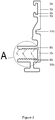
- the figure 1 is a vertical sectional view of a frame including a frame 1 supports and guides a single glazing 2 mounted slidably.
- the frame 1 is formed of rectilinear profiles 1a and 1b which may be of aluminum or other light alloy, where appropriate of another alloy or material, in particular synthetic, and of an insulating element 12 fitted into the sections 1a and 1b .
- the profile 1b is the symmetrical profile 1a relative to a vertical axis of symmetry.
- the profiles 1a and 1b each have a longitudinal flange 3a and 3b with, at their upper part, a pair of recessed flanges 4a, 5a and 4b, 5b which hold brushes 6a and 6b in contact with the support 17 of the glazing 2 and, at their lower part, respectively an internal boss 11a and 11b for centering the ball bearing 16.
- the sections 1a and 1b respectively have a pair of internal transverse wings 8a, 9a and 8b, 9b.
- the transverse wings of each section are parallel and directed in the same direction so as to create a space in which a rectangular section element can come to engage.
- the transverse wings 8a, 9a and 8b, 9b are dimensioned so as to fit the insulation element 12.
- the interlocking is defined when the two lateral faces of the insulation element 12 come into contact with the vertical surfaces elements 7a and 7b of the profiles 1a and 1b joining the two transverse wings 8a, 9a and 8b, 9b.
- the sections 1a and 1b being symmetrical, the widths of the transverse wings are less than half the width L of the insulation element.
- the insulation element is itself dimensioned to the mounting according to the thickness of the glazing 2.
- the length of the shaft 13 of the ball bearing 16 is also dimensioned according to the thickness of the glazing 2.
- the figure 2 has a vertical sectional view of a frame including a frame 1 supports and guides a single glazing 2, the latter being thicker than that of the figure 1 .
- the relative positions of the profiles 1a and 1b are modified with respect to the figure 1 , their spacing being greater, and the width L of the insulating member 12 is increased so as to create the desired interlock between the pairs of transverse wings 8a, 9a and 8b, 9b and the insulating member 12
- the width L of the insulation element 12 is defined as a function of the thickness of the glazing.
- the length of the shaft 13 is increased relative to that of the shaft shown in FIG. figure 1 .
- the transverse wings and the insulation element themselves ensure the connection of the two parts of the frame.
- the figure 3 has a vertical section of a profile 1b, constituent element of the frame shown on the figures 1 and 2 .
- the figure 4 is a detail view and in vertical section of the transverse wings of the section shown to the figure 3 .
- the inner surfaces of the lower and upper transverse flanges of the profiles intended to come into contact with the insulation element have planar portions S p separated by notched portions S c .
- the serrated portions S c of the internal surfaces are formed by a plurality of parallel lines in relief, each line having a substantially triangular profile and extending at least partially projecting from the plane defined by the planar portions S p .
- These raised lines may extend over only a portion of the length of the sections 1a and 1b or, in a preferred form, over the entire length of the sections 1a and 1b.
- other profiles may be chosen for the raised lines. In particular, it is conceivable to use trapezoidal profiles or any other polygonal profile of which at least one side forms an acute angle with the plane defined by the flat surfaces S p .
- each raised line has a profile in the form of a right triangle whose catheters are respectively in a plane parallel to that defined by the planar portions S p and perpendicular to this plane.
- the angle formed by the hypotenuse and the catheter perpendicular to the transverse wing is rounded off.
- the lines in relief in each of the serrated portions S c are juxtaposed to each other without discontinuity.
- the raised lines of the serrated portions S c formed on the upper transverse wings 8a and 8b are oriented opposite to the raised lines of the serrated portions S c formed on the lower transverse wings 9a and 9b.
- the inner surface of the transverse flange 8b is flat over a width corresponding to less than a quarter of the width of the transverse flange 8b.
- this flat portion S p adjoins a notched portion S c of a width corresponding to more than half the length of the transverse wing 8b.
- This notched portion S c then extends towards the free end of the transverse wing 8b in a flat portion S p .
- the inner surface of the transverse wing 9b is flat over a width corresponding to less than a quarter of the width of the transverse wing 9b.
- this flat portion S p adjoins a notched portion S c with a width corresponding to more than half the length of the transverse wing 9b.
- the free ends of the transverse wings 8b and 9b are rounded off to facilitate the interlocking of the insulation element.
- the figure 5 shows a detail view in section of the insulation element 12 of the Figure 1 .
- This element is made of pvc or other synthetic insulating material. It has a vertical axis of symmetry.
- the outer surfaces intended to come into contact with the internal surfaces of the transverse wings 8a, 9a and 8b, 9b comprise at least one attachment band S a , said attachment strip being configured to interact with a notched portion S c of one of the transverse wings so as to prevent the tool-free disconnection of the insulating element 12 and the sections 1a and 1b.
- This stringer S a may in particular have a sufficiently rough surface so as to grip the raised lines of the notched portions S c of the transverse wings.
- this stringer S has been formed by performing a cross-knurling of a portion of the outer surface of the insulating member 12.
- the term knurling means the operation which consists in make streaks on a surface.
- the obtaining process used here is a material deformation process. The material is indeed locally stamped so as to create over- and under-thicknesses with respect to the initial surface. This type of knurling can be obtained by means of rollers brought into contact with the workpiece or by forced rolling between racks. The over- and under-thicknesses obtained here with respect to the initial surface are between 0.1 mm and 0.7 mm.
- the surface is flat over a width corresponding to less than a quarter of the width of the element insulation.
- this flat surface Towards the vertical axis of symmetry of the insulating member, this flat surface abuts a surface S has cross-knurled at 30 ° of a width corresponding between a quarter and half the width of the element insulation, said surface knurled cross acting as a snap band.
- This crossed knurled surface then extends in the direction of the axis of symmetry of the insulation element into a surface S t having a right knurling over a width corresponding to less than a quarter of the width of the element. insulation.
- the right knurling is made in the direction of the length of the insulation element.
- this surface S t serves in particular as a sealing strip because it makes it possible to limit the infiltrations of water that can occur through the space separating the transverse wings and the insulation element. .
- the surface is then flat. With regard to the lower surface of the insulation element, at one of the lateral ends of the insulation element, the surface is flat over a width corresponding to less than a quarter of the width of the insulation element. insulation.
- this flat surface abuts a surface S has cross-knurled at 30 ° of a width corresponding between a quarter and half the width of the element insulation. This crossed knurled surface then extends to the axis of symmetry of the insulation member in a flat surface.
- the thickness of the insulation element is dimensioned with respect to the spacing of the transverse wings 8a and 9a or 8b and 9b so that the adjustment be of type clamping.
- the distance separating the lower and upper transverse wings 8a and 9a or 8b and 9b will advantageously be less than the thickness of the insulating member 12.
- the thermal insulation is provided by the insulation element 12 and the clamping type adjustment. Sealing is ensured, for its part, by the conjunction of the flat portions S p of the upper transverse flanges 8a and 8b and straight knurled surfaces S t of the insulating element 12 as well as by the clamping type adjustment. In fact, once the assembly is carried out, the straight striations of the surfaces S t , result of the right knurling, are intended to come into contact with a flat portion S p of the upper transverse wings 8a and 8b. Surprisingly, the Applicant has found that such a configuration greatly improves the seal compared to a configuration where the planar portions S p would be in contact with a flat surface or a knurled cross surface of the insulation member. 12.
- the profile 29, connected to the section 1a is a removable decorative element.
- the bosses 11a and 11b and the transverse wings 8a and 8b of the profiles respectively 1a and 1b respectively serve to center and maintain in the frame 1, between the longitudinal wings 3a and 3b, a support and rolling device 14.
- the device support 14 consists of an inverted U-shaped rail 15 straddling the upper transverse wings 8a and 8b, a series of shafts 13 traversing the rail 15 transversely and each carrying a ball bearing 16.
- the glazing 2 supported and guided in the frame 1 comprises a glass lathe 17 in which the glazing is capped.
- a tread 18 is applied under the glass turn 17 so as to rest the glazing 2 on the bearings 16.
- the brushes 6a and 6b guide the movement.
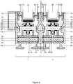
- the figure 6 presents a frame with two frames. In each of these frames, with the exception of the double profile 1c, we find the same elements as in the figure 1 so there is no need to list them again.
- the rectilinear double profile 1c may be aluminum or other light alloy, if necessary in another alloy or material, including synthetic.
- the double profile 1c has an axis of vertical symmetry and is presented in detail at figure 7 .
- the double profile 1c has two pairs of transverse wings 8c, 9c and 8d, 9d on either side of the profile. In each of these pairs, the transverse wings are parallel and directed in the same direction so as to create a space in which an element of rectangular section can come to engage.
- transverse wings 8c, 9c and 8d, 9d of the profile 1c are connected to the insulation elements 12a and 12b of the two adjacent frames.
- the internal surfaces of the transverse wings of the profile 1c intended to come into contact with the insulating elements 12a and 12b are similarly notched to the transverse wings of the single section 1b of the figure 1 detailed at figures 3 and 4 .
- the figure 8 shows, in horizontal section, the arrangement of glazing in a window frame with three frames and three glazings.
- Glazing 2a and 2b are sliding while glazing 2c is fixed.
- the glazings 2a and 2b, supported and guided in the frames, are capped in glass towers of different design than on the figure 1 , conditioned by the need for movement of the elements of the glazing.
- the vertical upright sides of the frames are spaced from each other by a distance which corresponds to the maximum extension with all three glazings.
- the glazings 2a and 2b are guided on their upper and lower horizontal sides by the profiles 1a and 1b of a frame 1 as presented on the figure 1 .
- the glazing 2a In the folded position, the glazing 2a is in abutment against a stop 30 held on a spacer 31.
- the lateral wings 20, which allow the attachment of the glazing to move it, comprise two segment segments 20a and 20b fixed to each other. other by means of screws or pins 21 with holding spacers 22a and 22b.
- the vertical upright of the glass tower consists of a profile 40 with a front plate 40a, a lateral gripping structure 40b, hollow and provided with a closing blade 40c projecting at the outer end of said front plate.
- the vertical upright of the glass tower consists of a U-shaped profile arrangement 40d with a wing retaining a brush 6a and a support flange intended to fit into the arrangement of U-shaped profile 50d of the neighboring frame.
- the element 40 of the glass tower is clamped against the glazing 2a by a spacer 41 actuated by a screw and nut system 42 accessible in the gripping structure 40b.
- the glass tower 44 of the fixed glazing 2c is housed in the space between the profiles 1c and 1d of the frame placed in the frame opposite the glazing 2a.
- This glass is identical to the one designated by 17 at figure 1 and engaged between the profiles 1a and 1b of the frame 1.
- a glass lathe 70 is mounted against the rear flank of the glazing 2c.
- the second glazing of the frame is placed, in the position of complete closure of the window, intermediate glazing in intermediate position between the first and the third which have just been described.
- the glass turn of this intermediate glazing 2b includes, at its two ends, vertical elements 50 and 60 respectively comprising a U-profile arrangement 50d and 60d.
- the figure 8 presents, in the deployed position of the three glazings 2a, 2b and 2c, the mutual engagement of the U-profile arrangements 40d and 50d and arrangements 60d and 70d. Indeed, the two U-shaped structures 40d and 50d are arranged in the opposite position, so as to create a mutual commitment.
- the structures 60d and 70d are also arranged in the reverse position.
- the mutual commitments of the U-shaped structures 40d, 50d and 60d, 70d are configured in such a way as to guarantee the sliding of the glazings 2a and 2b. Indeed, the glazings 2a and 2b can be brought into the open position by sliding in the direction of the fixed glazing 2c in the length of the frames.
Landscapes
- Engineering & Computer Science (AREA)
- Civil Engineering (AREA)
- Structural Engineering (AREA)
- Securing Of Glass Panes Or The Like (AREA)
- Wing Frames And Configurations (AREA)
Claims (5)
- Umrahmung für Wände, insbesondere für Schiebewände, insbesondere für Schiebefenster oder Nicht-Schiebefenster, welche eingerichtet ist, eine oder mehrere einfache oder mehrfache parallele Glasscheiben (2) einzuschließen und zu halten, und umfassend mindestens einen Rahmen (1) aus zwei Teilen, die aus Profilen (1a, 1b) bestehen und derart zusammengefügt sind, dass ihre relative Position modifizierbar ist, wobei jedes der Profile mindestens einen Längsflügel (3a; 3b), der eine Glasscheibe (2) einschließt, und mindestens ein Isolierelement (12) aufweist, wobei jedes der Profile (1a, 1b) mindestens ein Paar von parallelen Querflügeln umfasst, nämlich jeweils einen oberen Querflügel (8a; 8b) und einen unteren Querflügel (9a, 9b), die in das oder die Isolierelemente (12) eingreifen,
dadurch gekennzeichnet, dass die Querflügel (8a, 9a, 8b, 9b), deren Flächen dazu bestimmt sind, mit dem Isolierelement (12) in Kontakt zu gelangen, mindestens einen ebenen Abschnitt (Sp) und mindestens einen gezackten Abschnitt (Sc) umfassen, der aus mehreren parallelen Relieflinien gebildet ist, wobei die Relieflinien ein im Wesentlichen dreieckiges Profil besitzen und sich mindestens teilweise vorstehend in Bezug auf die Ebene erstrecken, die durch den ebenen Abschnitt definiert wird, und das Isolierelement (12), dessen Flächen dazu bestimmt sind, mit den Querflügeln (8a, 9a, 8b, 9b) in Kontakt zu gelangen, mindestens ein Verschlussband (Sa) umfasst, wobei das Verschlussband (Sa) durch eine Kreuzrändelung gebildet ist und ausgelegt ist, mit dem gezackten Abschnitt (Sc) der Querflügel (8a, 9a, 8b, 9b) zusammenzuwirken, die ausgelegt sind, die Verbindung der Abschnitte jedes Rahmens sicherzustellen,
wobei die Breite des Isolierelements (12) an die Montage in Abhängigkeit von der Dicke der Glasscheibe(n) (2) angepasst wird,
dadurch, dass die obere Fläche des Isolierelements (12), die dazu bestimmt ist, mit dem oberen Querflügel (8a; 8b) in Kontakt zu gelangen, mindestens ein Dichtungsband (St) umfasst, wobei das Dichtungsband ausgelegt ist, mit dem ebenen Abschnitt (Sp) des oberen Querflügels (8a; 8b) zusammenzuwirken, um das Eindringen von Wasser quer durch den Raum einzuschränken, der den oberen Querflügel (8a; 8b) und das Isolierelement (12) trennt;
und dadurch, dass das Dichtungsband (St) durch eine gerade Rändelung gebildet ist, die dazu bestimmt ist, mit dem ebenen Abschnitt (Sp) des oberen Querflügels (8a; 8b) in der montierten Position der Umrahmung in Kontakt zu gelangen. - Umrahmung nach Anspruch 1, dadurch gekennzeichnet, dass die Dicke des Isolierelements (12) größer oder gleich dem Abstand ist, der den oberen Querflügel (8a; 8b) und den unteren Querflügel (9a; 9b) trennt.
- Umrahmung nach einem der vorhergehenden Ansprüche, welche aus mehreren angesetzten Rahmen (1) gebildet ist,
dadurch gekennzeichnet, dass in jedem Rahmen ein Doppelprofil (1c) eine vertikale Symmetrieachse derart besitzt, dass die Querflügel (8c, 9c, 8d, 9d) dieses Profils mit den Isolierelementen (12a, 12b) zweier benachbarter Rahmen verbunden sind. - Umrahmung nach einem der vorhergehenden Ansprüche, dadurch gekennzeichnet, dass die Glasscheibe(n) (2; 2a, 2b) zwischen den Längsflügeln (3a; 3b; 3a, 3b, 3c) der Profile (1a, 1b; 1a, 1b, 1c) des Rahmens gehalten wird (werden), wobei diese mit Querflügeln (8a, 8b; 8a, 8c, 8d, 8b) für den Halt von Rolleneinrichtungen (14; 14a, 14b) im Rahmen (1) versehen sind, auf denen jede einfache oder mehrfache Glasscheibe liegt, die vom Rahmen gehalten wird, wobei die einfache oder mehrfache Glasscheibe in dem Rahmen gleitend montiert ist.
- Umrahmung nach Anspruch 5, dadurch gekennzeichnet, dass in jedem Rahmen (1) mehrere Rolleneinrichtungen (14; 14a, 14b) entlang der gesamten Länge der Unterseite des Rahmens ausgerichtet sind, eine Schiene (15; 15a, 15b) in der Form eines umgekehrten U auf den oberen Querflügeln (8a, 8b; 8a, 8c, 8d, 8b) der Profile (1a, 1b; 1a, 1c, 1d) des Rahmens platziert ist, und ein oder mehrere Kugellager (16; 16a, 16b) jeweils auf einem Arm (13; 13a, 13b) montiert sind, der rechtwinklig durch die Seiten der Schiene gestützt wird.
Priority Applications (4)
| Application Number | Priority Date | Filing Date | Title |
|---|---|---|---|
| EP10194169.8A EP2463470B9 (de) | 2010-12-08 | 2010-12-08 | Rahmen für Wände |
| PT101941698T PT2463470T (pt) | 2010-12-08 | 2010-12-08 | Armação para paredes |
| US13/066,260 US8534010B2 (en) | 2010-12-08 | 2011-04-11 | Framing for panels |
| US13/954,263 US8635819B2 (en) | 2010-12-08 | 2013-07-30 | Framing for panels |
Applications Claiming Priority (1)
| Application Number | Priority Date | Filing Date | Title |
|---|---|---|---|
| EP10194169.8A EP2463470B9 (de) | 2010-12-08 | 2010-12-08 | Rahmen für Wände |
Publications (3)
| Publication Number | Publication Date |
|---|---|
| EP2463470A1 EP2463470A1 (de) | 2012-06-13 |
| EP2463470B1 EP2463470B1 (de) | 2017-08-02 |
| EP2463470B9 true EP2463470B9 (de) | 2017-11-15 |
Family
ID=43969446
Family Applications (1)
| Application Number | Title | Priority Date | Filing Date |
|---|---|---|---|
| EP10194169.8A Not-in-force EP2463470B9 (de) | 2010-12-08 | 2010-12-08 | Rahmen für Wände |
Country Status (3)
| Country | Link |
|---|---|
| US (2) | US8534010B2 (de) |
| EP (1) | EP2463470B9 (de) |
| PT (1) | PT2463470T (de) |
Families Citing this family (10)
| Publication number | Priority date | Publication date | Assignee | Title |
|---|---|---|---|---|
| CA2795650C (en) * | 2011-11-09 | 2014-12-30 | Glastech Glazing Contractors Ltd. | Glazing anchorage system |
| PL3095946T3 (pl) * | 2015-05-18 | 2020-03-31 | Christian Michels | Okno przesuwne |
| DE102016105124A1 (de) * | 2016-03-18 | 2017-09-21 | SCHÜCO International KG | Schiebeflügel für eine Schiebetüranordnung |
| US10947772B2 (en) | 2017-10-24 | 2021-03-16 | Quaker Window Products Co. | Thermally enhanced multi-component glass doors and windows |
| US10107027B1 (en) | 2017-10-24 | 2018-10-23 | Quaker Window Products Co. | Thermally enhanced multi-component window |
| JP6997651B2 (ja) * | 2018-02-23 | 2022-02-04 | Ykk Ap株式会社 | 建具 |
| FR3095001B1 (fr) * | 2019-04-11 | 2021-04-30 | Titime | Chassis pour fenetre coulissante |
| IT201900004416U1 (it) * | 2019-12-06 | 2021-06-06 | Savio Thesan S P A | Serramento per ante scorrevoli |
| US11634940B2 (en) * | 2020-11-18 | 2023-04-25 | Goldbrecht Llc | Invisible sill—thermally broken |
| US20240018823A1 (en) * | 2022-07-14 | 2024-01-18 | Jeld-Wen, Inc. | Fenestration unit with sash retention system |
Family Cites Families (8)
| Publication number | Priority date | Publication date | Assignee | Title |
|---|---|---|---|---|
| FR2363686A2 (fr) * | 1976-08-31 | 1978-03-31 | Fey Adam | Fenetre ou porte coulissante |
| US5579616A (en) * | 1992-08-26 | 1996-12-03 | Farag; F. Aziz | Panel-securing system |
| GB2309728B (en) * | 1996-02-01 | 1999-09-08 | Lorient Polyprod Ltd | Structural frame member |
| EP1356172B1 (de) * | 2001-01-19 | 2009-12-02 | RIBIC, Walter | Bauelementsystem für vorgehängte fassaden, fassadenverkleidungen, wintergärten, schallschutzwände, messebauten, carports und dergleichen |
| US7520093B2 (en) * | 2004-01-13 | 2009-04-21 | Beat Guhl | Frame construction of a sliding door |
| NZ531715A (en) * | 2004-03-11 | 2006-10-27 | Hpj Holdings Ltd | Joiner assembly with forms for fixed and sliding panels covered by same cladding |
| US7246466B2 (en) * | 2004-07-21 | 2007-07-24 | Hi-Tech Energy Windows Ltd. | Extruded profile system for forming sliding fenestration products |
| EP2221440A1 (de) * | 2009-02-20 | 2010-08-25 | Orchidées Constructions S.A. | Zargen für Schiebefenster |
-
2010
- 2010-12-08 PT PT101941698T patent/PT2463470T/pt unknown
- 2010-12-08 EP EP10194169.8A patent/EP2463470B9/de not_active Not-in-force
-
2011
- 2011-04-11 US US13/066,260 patent/US8534010B2/en not_active Expired - Fee Related
-
2013
- 2013-07-30 US US13/954,263 patent/US8635819B2/en not_active Expired - Fee Related
Also Published As
| Publication number | Publication date |
|---|---|
| US8635819B2 (en) | 2014-01-28 |
| US20130312342A1 (en) | 2013-11-28 |
| EP2463470A1 (de) | 2012-06-13 |
| PT2463470T (pt) | 2017-09-15 |
| EP2463470B1 (de) | 2017-08-02 |
| US20120036810A1 (en) | 2012-02-16 |
| US8534010B2 (en) | 2013-09-17 |
Similar Documents
| Publication | Publication Date | Title |
|---|---|---|
| EP2463470B9 (de) | Rahmen für Wände | |
| EP0224290B1 (de) | Bauart einer abdeckbaren Bedachung | |
| EP3115525B1 (de) | Verstellbare und isolierende blende für eine sonnenschutzanlage | |
| EP2398990B1 (de) | Rahmen für schiebefenster | |
| EP2494121B3 (de) | Zwischenwandvorrichtung | |
| EP0112199B1 (de) | Rahmen in Öffnungen bestehend aus Metallprofilen mit unterbrochenen Wärmebrücken und Pressgerät für das Bearbeiten dieser Profile | |
| EP0001948A1 (de) | Anordnung zum Festhalten von Verglasungselementen oder dergleichen | |
| WO2012017144A2 (fr) | Éclisse pour le raccordement de deux pièces profilées en c | |
| EP0412904B1 (de) | Holzumrahmung mit einer Nut für die Verglasung | |
| EP4103442A1 (de) | System zum befestigen einer seitenverglasung eines transportmittels mit einem schloss | |
| FR2658549A1 (fr) | Profile de charpente en tole pliee, couverture de batiment comportant de tels profiles, et son procede de montage. | |
| EP0745750B1 (de) | Glaspaneel | |
| FR2994999A1 (fr) | Ouvrant de porte ou de fenetre | |
| WO2005106177A2 (fr) | Connecteur pour raccorder deux extremites creuses de profile | |
| EP0636752A1 (de) | Satz von Sandwich-Paneelen zur Verkleidung von Gebäuden | |
| FR2967442A1 (fr) | Huisserie pour porte ou fenetre composee de deux plaques de platre | |
| EP1201869A1 (de) | Kunststoffflügel, sowie sein Herstellungsverfahren und zweiflügelige Öffnung, z.B. für ein Fenster | |
| EP2216475B1 (de) | Rahmenpfosten | |
| EP1991752B1 (de) | Anordnung aus einer mehrfachverglasungseinheit und einem profil sowie profil für eine verglasungseinheit | |
| FR2753228A1 (fr) | Profil de jonction et de coupure thermique interpose entre des profiles aluminium utilises notamment dans la confection des cadres de fenetres ou de portes | |
| EP1722065A1 (de) | Platte mit Hohlprofilträgern zum aussteifen | |
| FR2815066A1 (fr) | Poignee de tirage laterale pour ouvrant coulissant de porte ou fenetre | |
| FR3032221A1 (fr) | Combinaison de profile parclose et de profile d'ouvrant en vue de la realisation de chassis d'ouvrant de fenetre et porte fenetre et procede de realisation d'ouvrants | |
| FR3132317A1 (fr) | Structure de verrière | |
| FR2769958A1 (fr) | Procede d'assemblage de lames profilees et lames pour realiser un panneau plan rigide |
Legal Events
| Date | Code | Title | Description |
|---|---|---|---|
| PUAI | Public reference made under article 153(3) epc to a published international application that has entered the european phase |
Free format text: ORIGINAL CODE: 0009012 |
|
| AK | Designated contracting states |
Kind code of ref document: A1 Designated state(s): AL AT BE BG CH CY CZ DE DK EE ES FI FR GB GR HR HU IE IS IT LI LT LU LV MC MK MT NL NO PL PT RO RS SE SI SK SM TR |
|
| AX | Request for extension of the european patent |
Extension state: BA ME |
|
| 17P | Request for examination filed |
Effective date: 20121211 |
|
| RAP1 | Party data changed (applicant data changed or rights of an application transferred) |
Owner name: ORCHIDEES CONSTRUCTIONS S.A. |
|
| RAP1 | Party data changed (applicant data changed or rights of an application transferred) |
Owner name: ORCHIDEES CONSTRUCTIONS S.A. |
|
| 17Q | First examination report despatched |
Effective date: 20160129 |
|
| GRAP | Despatch of communication of intention to grant a patent |
Free format text: ORIGINAL CODE: EPIDOSNIGR1 |
|
| INTG | Intention to grant announced |
Effective date: 20170222 |
|
| GRAS | Grant fee paid |
Free format text: ORIGINAL CODE: EPIDOSNIGR3 |
|
| GRAA | (expected) grant |
Free format text: ORIGINAL CODE: 0009210 |
|
| AK | Designated contracting states |
Kind code of ref document: B1 Designated state(s): AL AT BE BG CH CY CZ DE DK EE ES FI FR GB GR HR HU IE IS IT LI LT LU LV MC MK MT NL NO PL PT RO RS SE SI SK SM TR |
|
| REG | Reference to a national code |
Ref country code: GB Ref legal event code: FG4D Free format text: NOT ENGLISH |
|
| REG | Reference to a national code |
Ref country code: CH Ref legal event code: EP Ref country code: AT Ref legal event code: REF Ref document number: 914673 Country of ref document: AT Kind code of ref document: T Effective date: 20170815 |
|
| REG | Reference to a national code |
Ref country code: IE Ref legal event code: FG4D Free format text: LANGUAGE OF EP DOCUMENT: FRENCH |
|
| REG | Reference to a national code |
Ref country code: CH Ref legal event code: NV Representative=s name: ABREMA AGENCE BREVET ET MARQUES, GANGUILLET, CH |
|
| REG | Reference to a national code |
Ref country code: DE Ref legal event code: R096 Ref document number: 602010044024 Country of ref document: DE |
|
| REG | Reference to a national code |
Ref country code: PT Ref legal event code: SC4A Ref document number: 2463470 Country of ref document: PT Date of ref document: 20170915 Kind code of ref document: T Free format text: AVAILABILITY OF NATIONAL TRANSLATION Effective date: 20170911 |
|
| REG | Reference to a national code |
Ref country code: NL Ref legal event code: MP Effective date: 20170802 |
|
| REG | Reference to a national code |
Ref country code: AT Ref legal event code: MK05 Ref document number: 914673 Country of ref document: AT Kind code of ref document: T Effective date: 20170802 |
|
| REG | Reference to a national code |
Ref country code: FR Ref legal event code: PLFP Year of fee payment: 8 |
|
| REG | Reference to a national code |
Ref country code: LT Ref legal event code: MG4D |
|
| PG25 | Lapsed in a contracting state [announced via postgrant information from national office to epo] |
Ref country code: SE Free format text: LAPSE BECAUSE OF FAILURE TO SUBMIT A TRANSLATION OF THE DESCRIPTION OR TO PAY THE FEE WITHIN THE PRESCRIBED TIME-LIMIT Effective date: 20170802 Ref country code: NO Free format text: LAPSE BECAUSE OF FAILURE TO SUBMIT A TRANSLATION OF THE DESCRIPTION OR TO PAY THE FEE WITHIN THE PRESCRIBED TIME-LIMIT Effective date: 20171102 Ref country code: LT Free format text: LAPSE BECAUSE OF FAILURE TO SUBMIT A TRANSLATION OF THE DESCRIPTION OR TO PAY THE FEE WITHIN THE PRESCRIBED TIME-LIMIT Effective date: 20170802 Ref country code: HR Free format text: LAPSE BECAUSE OF FAILURE TO SUBMIT A TRANSLATION OF THE DESCRIPTION OR TO PAY THE FEE WITHIN THE PRESCRIBED TIME-LIMIT Effective date: 20170802 Ref country code: FI Free format text: LAPSE BECAUSE OF FAILURE TO SUBMIT A TRANSLATION OF THE DESCRIPTION OR TO PAY THE FEE WITHIN THE PRESCRIBED TIME-LIMIT Effective date: 20170802 Ref country code: NL Free format text: LAPSE BECAUSE OF FAILURE TO SUBMIT A TRANSLATION OF THE DESCRIPTION OR TO PAY THE FEE WITHIN THE PRESCRIBED TIME-LIMIT Effective date: 20170802 Ref country code: AT Free format text: LAPSE BECAUSE OF FAILURE TO SUBMIT A TRANSLATION OF THE DESCRIPTION OR TO PAY THE FEE WITHIN THE PRESCRIBED TIME-LIMIT Effective date: 20170802 |
|
| PGFP | Annual fee paid to national office [announced via postgrant information from national office to epo] |
Ref country code: FR Payment date: 20171221 Year of fee payment: 8 |
|
| PG25 | Lapsed in a contracting state [announced via postgrant information from national office to epo] |
Ref country code: ES Free format text: LAPSE BECAUSE OF FAILURE TO SUBMIT A TRANSLATION OF THE DESCRIPTION OR TO PAY THE FEE WITHIN THE PRESCRIBED TIME-LIMIT Effective date: 20170802 Ref country code: LV Free format text: LAPSE BECAUSE OF FAILURE TO SUBMIT A TRANSLATION OF THE DESCRIPTION OR TO PAY THE FEE WITHIN THE PRESCRIBED TIME-LIMIT Effective date: 20170802 Ref country code: GR Free format text: LAPSE BECAUSE OF FAILURE TO SUBMIT A TRANSLATION OF THE DESCRIPTION OR TO PAY THE FEE WITHIN THE PRESCRIBED TIME-LIMIT Effective date: 20171103 Ref country code: RS Free format text: LAPSE BECAUSE OF FAILURE TO SUBMIT A TRANSLATION OF THE DESCRIPTION OR TO PAY THE FEE WITHIN THE PRESCRIBED TIME-LIMIT Effective date: 20170802 Ref country code: PL Free format text: LAPSE BECAUSE OF FAILURE TO SUBMIT A TRANSLATION OF THE DESCRIPTION OR TO PAY THE FEE WITHIN THE PRESCRIBED TIME-LIMIT Effective date: 20170802 Ref country code: IS Free format text: LAPSE BECAUSE OF FAILURE TO SUBMIT A TRANSLATION OF THE DESCRIPTION OR TO PAY THE FEE WITHIN THE PRESCRIBED TIME-LIMIT Effective date: 20171202 Ref country code: BG Free format text: LAPSE BECAUSE OF FAILURE TO SUBMIT A TRANSLATION OF THE DESCRIPTION OR TO PAY THE FEE WITHIN THE PRESCRIBED TIME-LIMIT Effective date: 20171102 |
|
| PGFP | Annual fee paid to national office [announced via postgrant information from national office to epo] |
Ref country code: GB Payment date: 20171221 Year of fee payment: 8 Ref country code: PT Payment date: 20171205 Year of fee payment: 8 |
|
| PG25 | Lapsed in a contracting state [announced via postgrant information from national office to epo] |
Ref country code: RO Free format text: LAPSE BECAUSE OF FAILURE TO SUBMIT A TRANSLATION OF THE DESCRIPTION OR TO PAY THE FEE WITHIN THE PRESCRIBED TIME-LIMIT Effective date: 20170802 Ref country code: DK Free format text: LAPSE BECAUSE OF FAILURE TO SUBMIT A TRANSLATION OF THE DESCRIPTION OR TO PAY THE FEE WITHIN THE PRESCRIBED TIME-LIMIT Effective date: 20170802 Ref country code: CZ Free format text: LAPSE BECAUSE OF FAILURE TO SUBMIT A TRANSLATION OF THE DESCRIPTION OR TO PAY THE FEE WITHIN THE PRESCRIBED TIME-LIMIT Effective date: 20170802 |
|
| PGFP | Annual fee paid to national office [announced via postgrant information from national office to epo] |
Ref country code: CH Payment date: 20180104 Year of fee payment: 8 |
|
| REG | Reference to a national code |
Ref country code: DE Ref legal event code: R097 Ref document number: 602010044024 Country of ref document: DE |
|
| PG25 | Lapsed in a contracting state [announced via postgrant information from national office to epo] |
Ref country code: EE Free format text: LAPSE BECAUSE OF FAILURE TO SUBMIT A TRANSLATION OF THE DESCRIPTION OR TO PAY THE FEE WITHIN THE PRESCRIBED TIME-LIMIT Effective date: 20170802 Ref country code: IT Free format text: LAPSE BECAUSE OF FAILURE TO SUBMIT A TRANSLATION OF THE DESCRIPTION OR TO PAY THE FEE WITHIN THE PRESCRIBED TIME-LIMIT Effective date: 20170802 Ref country code: SM Free format text: LAPSE BECAUSE OF FAILURE TO SUBMIT A TRANSLATION OF THE DESCRIPTION OR TO PAY THE FEE WITHIN THE PRESCRIBED TIME-LIMIT Effective date: 20170802 Ref country code: SK Free format text: LAPSE BECAUSE OF FAILURE TO SUBMIT A TRANSLATION OF THE DESCRIPTION OR TO PAY THE FEE WITHIN THE PRESCRIBED TIME-LIMIT Effective date: 20170802 |
|
| PLBE | No opposition filed within time limit |
Free format text: ORIGINAL CODE: 0009261 |
|
| STAA | Information on the status of an ep patent application or granted ep patent |
Free format text: STATUS: NO OPPOSITION FILED WITHIN TIME LIMIT |
|
| REG | Reference to a national code |
Ref country code: DE Ref legal event code: R119 Ref document number: 602010044024 Country of ref document: DE |
|
| 26N | No opposition filed |
Effective date: 20180503 |
|
| PG25 | Lapsed in a contracting state [announced via postgrant information from national office to epo] |
Ref country code: SI Free format text: LAPSE BECAUSE OF FAILURE TO SUBMIT A TRANSLATION OF THE DESCRIPTION OR TO PAY THE FEE WITHIN THE PRESCRIBED TIME-LIMIT Effective date: 20170802 |
|
| REG | Reference to a national code |
Ref country code: IE Ref legal event code: MM4A |
|
| PG25 | Lapsed in a contracting state [announced via postgrant information from national office to epo] |
Ref country code: MT Free format text: LAPSE BECAUSE OF FAILURE TO SUBMIT A TRANSLATION OF THE DESCRIPTION OR TO PAY THE FEE WITHIN THE PRESCRIBED TIME-LIMIT Effective date: 20170802 Ref country code: LU Free format text: LAPSE BECAUSE OF NON-PAYMENT OF DUE FEES Effective date: 20171208 |
|
| REG | Reference to a national code |
Ref country code: BE Ref legal event code: MM Effective date: 20171231 |
|
| PG25 | Lapsed in a contracting state [announced via postgrant information from national office to epo] |
Ref country code: DE Free format text: LAPSE BECAUSE OF NON-PAYMENT OF DUE FEES Effective date: 20180703 Ref country code: IE Free format text: LAPSE BECAUSE OF NON-PAYMENT OF DUE FEES Effective date: 20171208 |
|
| PG25 | Lapsed in a contracting state [announced via postgrant information from national office to epo] |
Ref country code: BE Free format text: LAPSE BECAUSE OF NON-PAYMENT OF DUE FEES Effective date: 20171231 |
|
| PG25 | Lapsed in a contracting state [announced via postgrant information from national office to epo] |
Ref country code: MC Free format text: LAPSE BECAUSE OF FAILURE TO SUBMIT A TRANSLATION OF THE DESCRIPTION OR TO PAY THE FEE WITHIN THE PRESCRIBED TIME-LIMIT Effective date: 20170802 Ref country code: HU Free format text: LAPSE BECAUSE OF FAILURE TO SUBMIT A TRANSLATION OF THE DESCRIPTION OR TO PAY THE FEE WITHIN THE PRESCRIBED TIME-LIMIT; INVALID AB INITIO Effective date: 20101208 |
|
| PG25 | Lapsed in a contracting state [announced via postgrant information from national office to epo] |
Ref country code: PT Free format text: LAPSE BECAUSE OF NON-PAYMENT OF DUE FEES Effective date: 20190611 |
|
| REG | Reference to a national code |
Ref country code: CH Ref legal event code: PL |
|
| GBPC | Gb: european patent ceased through non-payment of renewal fee |
Effective date: 20181208 |
|
| PG25 | Lapsed in a contracting state [announced via postgrant information from national office to epo] |
Ref country code: FR Free format text: LAPSE BECAUSE OF NON-PAYMENT OF DUE FEES Effective date: 20181231 Ref country code: CY Free format text: LAPSE BECAUSE OF NON-PAYMENT OF DUE FEES Effective date: 20170802 |
|
| PG25 | Lapsed in a contracting state [announced via postgrant information from national office to epo] |
Ref country code: MK Free format text: LAPSE BECAUSE OF FAILURE TO SUBMIT A TRANSLATION OF THE DESCRIPTION OR TO PAY THE FEE WITHIN THE PRESCRIBED TIME-LIMIT Effective date: 20170802 |
|
| PG25 | Lapsed in a contracting state [announced via postgrant information from national office to epo] |
Ref country code: LI Free format text: LAPSE BECAUSE OF NON-PAYMENT OF DUE FEES Effective date: 20181231 Ref country code: GB Free format text: LAPSE BECAUSE OF NON-PAYMENT OF DUE FEES Effective date: 20181208 Ref country code: CH Free format text: LAPSE BECAUSE OF NON-PAYMENT OF DUE FEES Effective date: 20181231 |
|
| PG25 | Lapsed in a contracting state [announced via postgrant information from national office to epo] |
Ref country code: TR Free format text: LAPSE BECAUSE OF FAILURE TO SUBMIT A TRANSLATION OF THE DESCRIPTION OR TO PAY THE FEE WITHIN THE PRESCRIBED TIME-LIMIT Effective date: 20170802 |
|
| PG25 | Lapsed in a contracting state [announced via postgrant information from national office to epo] |
Ref country code: AL Free format text: LAPSE BECAUSE OF FAILURE TO SUBMIT A TRANSLATION OF THE DESCRIPTION OR TO PAY THE FEE WITHIN THE PRESCRIBED TIME-LIMIT Effective date: 20170802 |