EP2463166B1 - System und Verfahren zur Bereitstellung einer Bremsanzeige für elektrische Bremsen - Google Patents
System und Verfahren zur Bereitstellung einer Bremsanzeige für elektrische Bremsen Download PDFInfo
- Publication number
- EP2463166B1 EP2463166B1 EP20110250745 EP11250745A EP2463166B1 EP 2463166 B1 EP2463166 B1 EP 2463166B1 EP 20110250745 EP20110250745 EP 20110250745 EP 11250745 A EP11250745 A EP 11250745A EP 2463166 B1 EP2463166 B1 EP 2463166B1
- Authority
- EP
- European Patent Office
- Prior art keywords
- braking
- ema
- driver
- emergency
- braking signal
- Prior art date
- Legal status (The legal status is an assumption and is not a legal conclusion. Google has not performed a legal analysis and makes no representation as to the accuracy of the status listed.)
- Active
Links
Images


Classifications
-
- B—PERFORMING OPERATIONS; TRANSPORTING
- B60—VEHICLES IN GENERAL
- B60T—VEHICLE BRAKE CONTROL SYSTEMS OR PARTS THEREOF; BRAKE CONTROL SYSTEMS OR PARTS THEREOF, IN GENERAL; ARRANGEMENT OF BRAKING ELEMENTS ON VEHICLES IN GENERAL; PORTABLE DEVICES FOR PREVENTING UNWANTED MOVEMENT OF VEHICLES; VEHICLE MODIFICATIONS TO FACILITATE COOLING OF BRAKES
- B60T8/00—Arrangements for adjusting wheel-braking force to meet varying vehicular or ground-surface conditions, e.g. limiting or varying distribution of braking force
- B60T8/17—Using electrical or electronic regulation means to control braking
- B60T8/1701—Braking or traction control means specially adapted for particular types of vehicles
- B60T8/1703—Braking or traction control means specially adapted for particular types of vehicles for aircrafts
-
- B—PERFORMING OPERATIONS; TRANSPORTING
- B60—VEHICLES IN GENERAL
- B60T—VEHICLE BRAKE CONTROL SYSTEMS OR PARTS THEREOF; BRAKE CONTROL SYSTEMS OR PARTS THEREOF, IN GENERAL; ARRANGEMENT OF BRAKING ELEMENTS ON VEHICLES IN GENERAL; PORTABLE DEVICES FOR PREVENTING UNWANTED MOVEMENT OF VEHICLES; VEHICLE MODIFICATIONS TO FACILITATE COOLING OF BRAKES
- B60T13/00—Transmitting braking action from initiating means to ultimate brake actuator with power assistance or drive; Brake systems incorporating such transmitting means, e.g. air-pressure brake systems
- B60T13/74—Transmitting braking action from initiating means to ultimate brake actuator with power assistance or drive; Brake systems incorporating such transmitting means, e.g. air-pressure brake systems with electrical assistance or drive
- B60T13/741—Transmitting braking action from initiating means to ultimate brake actuator with power assistance or drive; Brake systems incorporating such transmitting means, e.g. air-pressure brake systems with electrical assistance or drive acting on an ultimate actuator
-
- B—PERFORMING OPERATIONS; TRANSPORTING
- B60—VEHICLES IN GENERAL
- B60T—VEHICLE BRAKE CONTROL SYSTEMS OR PARTS THEREOF; BRAKE CONTROL SYSTEMS OR PARTS THEREOF, IN GENERAL; ARRANGEMENT OF BRAKING ELEMENTS ON VEHICLES IN GENERAL; PORTABLE DEVICES FOR PREVENTING UNWANTED MOVEMENT OF VEHICLES; VEHICLE MODIFICATIONS TO FACILITATE COOLING OF BRAKES
- B60T8/00—Arrangements for adjusting wheel-braking force to meet varying vehicular or ground-surface conditions, e.g. limiting or varying distribution of braking force
- B60T8/32—Arrangements for adjusting wheel-braking force to meet varying vehicular or ground-surface conditions, e.g. limiting or varying distribution of braking force responsive to a speed condition, e.g. acceleration or deceleration
- B60T8/88—Arrangements for adjusting wheel-braking force to meet varying vehicular or ground-surface conditions, e.g. limiting or varying distribution of braking force responsive to a speed condition, e.g. acceleration or deceleration with failure responsive means, i.e. means for detecting and indicating faulty operation of the speed responsive control means
- B60T8/885—Arrangements for adjusting wheel-braking force to meet varying vehicular or ground-surface conditions, e.g. limiting or varying distribution of braking force responsive to a speed condition, e.g. acceleration or deceleration with failure responsive means, i.e. means for detecting and indicating faulty operation of the speed responsive control means using electrical circuitry
-
- B—PERFORMING OPERATIONS; TRANSPORTING
- B60—VEHICLES IN GENERAL
- B60T—VEHICLE BRAKE CONTROL SYSTEMS OR PARTS THEREOF; BRAKE CONTROL SYSTEMS OR PARTS THEREOF, IN GENERAL; ARRANGEMENT OF BRAKING ELEMENTS ON VEHICLES IN GENERAL; PORTABLE DEVICES FOR PREVENTING UNWANTED MOVEMENT OF VEHICLES; VEHICLE MODIFICATIONS TO FACILITATE COOLING OF BRAKES
- B60T2270/00—Further aspects of brake control systems not otherwise provided for
- B60T2270/40—Failsafe aspects of brake control systems
- B60T2270/402—Back-up
-
- B—PERFORMING OPERATIONS; TRANSPORTING
- B60—VEHICLES IN GENERAL
- B60T—VEHICLE BRAKE CONTROL SYSTEMS OR PARTS THEREOF; BRAKE CONTROL SYSTEMS OR PARTS THEREOF, IN GENERAL; ARRANGEMENT OF BRAKING ELEMENTS ON VEHICLES IN GENERAL; PORTABLE DEVICES FOR PREVENTING UNWANTED MOVEMENT OF VEHICLES; VEHICLE MODIFICATIONS TO FACILITATE COOLING OF BRAKES
- B60T2270/00—Further aspects of brake control systems not otherwise provided for
- B60T2270/40—Failsafe aspects of brake control systems
- B60T2270/413—Plausibility monitoring, cross check, redundancy
Definitions
- Aircraft and other vehicles typically utilize emergency and/or parking brake systems to activate the brakes during emergency situations where normal braking systems usually fail and during situations where the aircraft is parked.
- emergency and/or parking brake systems may be electrically or hydraulically operated.
- An electrically operated braking system for a vehicle generally includes a brake control unit (BCU) that receives a control signal, for example, from a pedal and/or switch in the vehicle.
- the BCU utilizes the control signal to command an electromechanical actuator controller (EMAC) to power an actuator coupled to a wheel of the vehicle.
- EMAC electromechanical actuator controller
- the power provided by the EMAC to the actuator facilitates exerting a braking force on the wheel to cause the vehicle to slow down and/or come to a stop.
- These electrically operated braking systems may include systems for providing emergency and/or parking brake functionality to the aircraft. Examples of such systems are disclosed in commonly-assigned U.S. Patent Application Serial No. 12/429,303 , entitled “Electric Brake Architecture With Dissimilar Emergency Braking Path” (filed April 24, 2009) and U.S. Patent Application Serial No. 12/433,050 , entitled “Differential Emergency/Park Electric Brake System” (filed April 30, 2009), as well as in US Patent No. 6 296 325 B1 .
- Various embodiments relate to systems and methods for sensing current drawn and/or power consumed by an electromechanical actuator (EMA) in order to determine whether a braking force is being applied by the EMA.
- the current drawn is proportional to the braking force being applied by the EMA.
- Current drawn by a plurality of EMAs may be measured at a single location to reduce circuitry and wiring, as opposed to measuring the current drawn individually by each EMA.
- the current may be sensed at the single location during an emergency/park braking operation to determine whether the desired braking is being applied. Further, in an embodiment, the current may be sensed at the single location to provide a system for cross-checking the behavior of a normal braking operation.
- a system for electrical braking of a vehicle comprises a power bus coupled to a first driver associated with a first electromechanical actuator (EMA).
- the power bus is also coupled to a second driver associated with a second EMA, and the first EMA and the second EMA are associated with a wheel of the vehicle.
- the power bus provides braking power to the first EMA via the first driver and to the second EMA via the second driver.
- the system further comprises a normal braking command interface for providing a first braking signal to the first driver and a second braking signal to the second driver.
- the system comprises an emergency/park brake interface for sending a first emergency/park braking signal to the first driver and a second emergency/park braking signal to the second driver.
- the first emergency/park braking signal and the second emergency/park braking signal bypass the normal braking command interface.
- a sensor is coupled to the power bus for measuring a current at a single location of the power bus, and the current is proportional to a braking force exerted by the first EMA and the second EMA on the wheel.
- the current measured by the sensor may indicate to a vehicle operator that the first EMA and the second EMA are exerting the braking force on the wheel.
- the current measured by the sensor may relate to at least one of a drawn current and a consumed power, and the current may indicate to a vehicle operator that the braking force complies with the first emergency/park braking signal and the second emergency/park braking signal.
- the normal braking command interface comprises a brake control unit (BCU), and the first braking signal and the second braking signal include a normal braking signal from a normal braking signal interface of the vehicle.
- the current measured by the sensor may indicate to a vehicle operator that the braking force complies with the normal braking signal.
- the first driver is disposed in the first EMA and the second driver is disposed in the second EMA.
- the system may comprise an electromechanical actuator controller (EMAC), and the first driver and the second driver may be disposed in the EMAC.
- EMAC electromechanical actuator controller
- the EMAC is coupled to the BCU for receiving the first braking signal and the second braking signal from the BCU, and the EMAC comprises a processor coupled to the first driver and the second driver for instructing the first EMA and the second EMA to exert the braking force on the wheel.
- the EMAC comprises a plurality of EMA drivers for providing a plurality of driving signals to a plurality of EMAs, and the sensor measures the current at the single location for estimating the braking force exerted by the plurality of EMAs.
- the first emergency/park braking signal and the second emergency/park braking signal bypass the processor in the EMAC.
- the system further comprises a power controller coupled to the power bus for providing power to the first driver and the second driver in response to at least one of the first braking signal, the second braking signal, the first emergency/park braking signal, or the second emergency/park braking signal.
- a second sensor may be disposed between the power controller and the first driver and the second driver, and the second sensor is for measuring, at a second single location, the current associated with at least one of the first braking signal, the second braking signal, the first emergency/park braking signal, or the second emergency/park braking signal.
- a system for electrical braking of a vehicle comprises a power bus coupled to a first driver associated with a first EMA.
- the power bus is also coupled to a second driver associated with a second EMA, and the first EMA and the second EMA are associated with a wheel of the vehicle.
- the power bus provides braking power to the first EMA via the first driver and to the second EMA via the second driver.
- a normal braking command interface provides a first braking signal to the first driver and a second braking signal to the second driver.
- An emergency/park brake interface sends a first emergency/park braking signal to the first driver and a second emergency/park braking signal to the second driver, and the first emergency/park braking signal and the second emergency/park braking signal bypass the normal braking command interface.
- the system further comprises a power controller coupled to the power bus and the first driver and the second driver.
- a sensor is coupled between the power - bus and the first driver and the second driver for measuring a current at a single location, wherein the current is proportional to a braking force exerted by the first EMA and the second EMA on the wheel.
- a method for electrical braking of a vehicle comprises sending a first braking signal from a normal braking command interface to a first driver associated with a first electromechanical actuator (EMA).
- a second braking signal is sent from the normal braking command interface to a second driver associated with a second EMA, and the first EMA and the second EMA exert a braking force on a wheel of the vehicle.
- EMA electromechanical actuator
- a first emergency/park braking signal is sent from an emergency/park brake interface to the first driver, and the first emergency/park braking signal bypasses the normal braking command interface.
- a second emergency/park braking signal is sent from an emergency/park brake interface to the second driver, and the second emergency/park braking signal bypasses the normal braking command interface.
- Braking power is provided from a power bus, through a power controller and through the first driver and the second driver to the first EMA and the second EMA.
- Current is measured at a single location with a sensor coupled between a power source and the first driver and the second driver, and the current is proportional to the braking force exerted by the first EMA and the second EMA on the wheel.
- the method further comprises sending the first braking signal and the second braking signal from a brake control unit to a processor in an EMAC, and the normal braking command interface includes the BCU.
- a processor controls a plurality of braking forces exerted by a plurality of EMAs.
- the method comprises cross-checking a desired braking force associated with the first braking signal and the second braking signal and the first EMA and the second EMA using the current measured at the single location.
- the method may further comprise feeding a signal corresponding to the current measured at the single location through the normal braking command interface to facilitate cross-checking the braking force exerted by the first EMA and the second EMA.
- measuring the current comprises measuring an amount of current drawn by the first EMA and the second EMA at the single location, and the amount of current drawn is proportional to the braking force exerted by the first EMA and the second EMA on the wheel.
- the method may comprise indicating to a vehicle operator that the first EMA and the second EMA are exerting the braking force on the wheel in accordance with at least one of the first braking signal, the second braking signal, the first emergency/park braking signal, or the second emergency/park braking signal..
- FIG. 1 illustrates a schematic representation of an electrical braking system according to an embodiment.
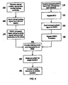
- FIG. 4 illustrates a flow chart representing an electrical braking method according to an embodiment.
- any reference to attached, fixed, connected or the like may include permanent, removable, temporary, partial, full and/or any other possible attachment option.
- systems and methods disclosed herein may be incorporated into anything needing a brake or having a wheel, or into any vehicle such as, for example, an aircraft, a train, a bus, an automobile and the like.
- an electrical braking system 10 comprises a normal braking command interface, such as a brake control unit (BCU) 12 that carries out braking operations of a vehicle such as an aircraft.
- the BCU 12 receives operator inputs, brake pedal inputs, autobrake inputs, anti-skid inputs, emergency brake inputs, parking brake inputs, and the like.
- interface as used herein and in the claims (e.g ., "normal braking command interface,” “normal braking signal interface” or “emergency/park interface” as described below) may refer to pedals, handles, levers, buttons, dials, switches, digital displays, touch screens, computers, processors, and the like.
- the BCU 12 may receive inputs from other sensors, such as wheel speed sensors 14, Additionally, the BCU 12 may include a normal braking signal interface that allows a vehicle operator to provide a braking indication to the BCU 12.
- the BCU 12 may comprise various channels 15, 16 to facilitate communicating with the EMACs 24. These channels 15, 16 may be used to provide redundant commands to the EMACs 24 to increase the safety of the braking system 10.
- the EMACs 24 may not be employed, and, instead, the BCU 12 may communicate with electromechanical actuators (EMAs) as discussed further below.
- EMAs electromechanical actuators
- Such a configuration may be referred to as a distributed case, and the drivers and other processing functionality utilized to effectuate braking may be carried out substantially at each of the EMAs on the wheels of the vehicle.
- an emergency/park brake interface 22 also sends braking commands to the EMACs 24 and/or to the EMAs without going through an EMAC 24.
- the emergency/park interface 22 may indicate that normal, emergency, and/or park braking is desired.
- emergency/park brake interface 22 may carry out any braking operation that reduces and/or slows down the speed of a vehicle in response to an unexpected, exigent, and/or time-sensitive event.
- emergency/park brake interface 22 may carry out any braking operation that facilitates maintaining the vehicle in a stopped condition or preventing the vehicle from moving.
- the emergency and park braking setting may be the same or different settings.
- braking functionality is carried out by the EMACs in accordance with the command signals from the BCU 12.
- emergency and/or park braking is indicated by the emergency/park interface 22
- braking functionality is carried out by the EMACs 24 in accordance with the command signal from the emergency/park interface 22.
- braking functionality is carried out by the EMAs in accordance with the command signals from the BCU 12.
- emergency and/or park braking is indicated by the emergency/park interface 22
- braking functionality is similarly carried out by the EMAs 24, in accordance with the command signal from the emergency/park interface 22 that bypasses the BCU 12.
- the EMACs 24 are electrically coupled to one or more electromechanical actuators (EMAs) 26.
- the EMAs 26 exert a braking force on a brake disk stack 32 by driving a ram 30 into the brake disk stack 32. Driving the ram 30 into the brake disk stack 32 causes a rotation of a wheel 34 to slow down and/or stop.
- Each EMA 26 may exert a braking force on the brake disk stack 32 that is independent from or the same as the braking force exerted by one or more other EMAs 26.
- the EMAC determines whether to use the normal braking signal from the BCU 12 or the emergency/park brake signal from the emergency/park interface 22 to actuate the EMAs 26. In an embodiment where EMACs are not employed, the BCU 12 and the emergency/park interface 22 may communicate with the EMAs 26 to effectuate braking.
- the EMACs 24 are powered from power sources 40, 42 via power busses 41, 43.
- the power source 40 provides power to the EMAC 24 via the power bus 41. This power provided to the EMAC 24 at a single input to the EMAC 24 via power bus 41 may be utilized to provide power to one or more of the EMAs 26.
- the power sources 40, 42 may include 270 VDC power sources. In embodiments where backup power is used, the power sources 40, 42 may include 28 VDC battery backup power sources. It should be understood that power sources 40, 42 may be any power source capable of providing braking power to the EMAs, and this power may be provided by various aircraft systems and/or subsystems.
- the power sources 40, 42 provide power to the EMAs 26 via the power busses 41, 43.
- the conductors in the power bus may be grouped together and/or carried over fewer and/or larger conductors up to a location proximate certain EMAs, for example, near the top of a landing gear strut. Then the conductors may branch off to carry the power to the individual EMAs. In this manner, as will be described further below, the currant drawn may be measured at the power bus at a single location in order to infer a braking condition of a plurality of EMAs.
- a current flowing in the power busses 41, 43 is drawn in order to drive the EMAs 26 and the rams 30.
- This drawn current and/or power consumed by the EMAs 26 is proportional to the actual amount of braking force applied by the EMAs 26 that are being driven by the power source 40. Measuring this drawn current and/or consumed power may indicate to an operator of the aircraft that a certain amount of braking force is being applied to the brake stacks 32 and the wheels 34. For example, if no current was being drawn, the operator would know that there was likely no braking force being applied.
- Various embodiments disclosed herein provide ways for the operator to have an indication that braking force is being applied by measuring the amount of current drawn during an emergency and/or park braking operation. Further, measuring current may also allow the operator to crosscheck braking force being applied during a normal braking operation.
- sensors 50 may be utilized to measure the amount of current drawn during a braking operation.
- the sensor 50 may be located on the power bus 41 between the power source 40 and the EMAC 24. Measuring the drawn current at a single location, as opposed to measuring current associated with each individual EMA 26, reduces the number of wires that run to the EMAs 26, which saves cost and weight.
- the sensor 50 may be located at a single location prior to the individual wires for a plurality of EMAs branching off to the EMAs (see, e.g., FIG. 3 ).
- the EMAC 24 comprises processors 55 that receive braking commands from the BCU 12 during normal braking operations.
- the processors 55 utilize the braking commands to instruct drivers 57 to drive the EMAs 26 in accordance with an operator input, for example, from a pedal or autobrake switch.
- the processors 55 include microcontrollers to facilitate controlling normal braking operation, and multiple processors 55 may be used for redundancy.
- the drivers are contained within a driver bank 56, and each driver 57 is associated with an EMA 26 to control actuation of the EMA 26.
- the processors 55 are also coupled to power controllers 60.
- the power controllers 60 control which of the normal braking signal or the emergency/park braking signal is delivered to the driver banks 56 for actuation of the EMAs 26. If the power controllers 60 indicate that a normal braking signal is to be applied, the driver banks 56 and the drivers 57 are controlled by processors 55.
- the power controllers 60 bypass the processors 55 and deliver the emergency/park braking command to the driver banks 56.
- the emergency/park braking signal bypasses both the BCU 12 and the processors 55. Eliminating the processors 55 from the circuit path of the emergency/park braking signal simplifies the circuitry involved.
- the power controllers 60 may include a simple switch that closes or opens when the emergency/park braking signal is indicated, in order to bypass the processors 55.
- microprocessors are not involved in the circuit path during emergency/park braking, less development assurance is utilized.
- the EMAs 26 may individually include a driver 57 for effectuating braking by the EMAs 26.
- the drivers 57 may be located together in a group of drivers near the EMAs that are driven by the drivers 57.
- the processors 55 and/or power controllers 60 may be located in each EMA 26, and/or the processors 55, drivers 57, and/or power controllers 60 may be located near a group of EMAs 26 ( e.g., near the top of a landing gear strut) to facilitate controlling and driving a group of EMAs 26.
- the descriptions of drivers, processors, and power controllers herein should thus be understood to be applicable to the distributed case where the drivers 57, processors 55, and/or power controllers 60 are located in and/or proximate the EMAs 26, instead of in the EMACs 24.
- the emergency/park braking signal may bypass the BCU 12 and the processors 55 (wherever they are located) and drive the drivers 57 to effectuate braking of the vehicle.
- the sensors 51 may be disposed between the power controllers 60 and the driver banks 56 (and/or between groups of the individual drivers in the distributed case) in order to measure the current at a single location for each individual driver bank 56 (or group of drivers 57). Measuring the current along existing wiring reduces the need to run additional wiring to each of the drivers 57 and/or EMAs 26 in order to sense the current.
- the processors 55 may be able to determine the amount of braking force being applied by each of the EMAs 26 because the processors 55 are communicatively coupled to each of the EMAs 26 via the drivers 57. This coupling allows the processors 55 to determine the braking force being applied. However, because the sensor 50 may also sense a current drawn during normal braking operations, the sensor 50 may be utilized to crosscheck the braking force determined by the processors 55 to assess whether or not a normal braking force is actually being applied.
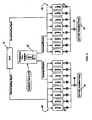
- FIG. 3 illustrates a schematic representation of an emergency/park braking component according to an embodiment.
- FIG. 3 illustrates both a case where an EMAC is present (e.g. , drivers 57 are located with an EMAC) and where an EMAC is not present ( e.g. , drivers 57 are individually located in the EMAs or near the EMAs).
- Emergency/park interface 22 provides a command/enable signal to the drivers 57.
- the power sources 40, 42 provide 270 VDC actuation power to the drivers 57.
- the command/enable signal and the actuation power allows the drivers to cause the EMAs to effectuate braking of the vehicle.
- the drawn current measured at a point between the power sources 40, 42 and the drivers 57, is proportional to the actual braking force being applied by the EMAs.
- each set 62, 63 of the drivers 57 may include eight drivers 57 that drive eight EMAs.
- the current could be measured at each location "B" in order to individually determine the current drawn and/or power consumed by each EMA.
- measuring the current at each individual driver 57 would require more wiring and circuitry than measuring the current at the single location "A" with the sensors 50 for each set 62, 63 of the drivers 57.
- the sensor 50 may also be utilized to crosscheck the braking force being applied during normal braking.
- the signal from the sensor 50 may be fed through the normal braking command interface (e.g. , BCU 12) to facilitate crosschecking the braking force exerted by the EMAs.
- the BCU receives a normal braking command from an operator of a vehicle, a brake input device, an anti-skid controller and/or the like.
- the BCU then sends the normal braking signal to the EMAC at step 105.
- the EMAC processor reads the normal braking signal and provides a braking instruction to the EMA driver.
- the EMAC at step 140, provides a braking instruction and braking power from the power controller to the EMA.
- the current is measured at a single location, as discussed above (step 145), and the braking system provides a braking indication to the operator of the vehicle (step 150) that may be crosschecked with an indication of normal braking received through the normal braking system.
- the BCU receives a normal braking command from an operator of a vehicle, a brake input device, an anti-skid controller and/or the like.
- the BCU then sends the normal braking signal to the various EMAs.
- the processors in the EMAs (or processors controlling groups of EMAs) read the normal braking signal and provide a braking instruction to the EMA drivers in the individual EMAs (or near the EMAs).
- a braking power from the power controller is provided to the EMAs.
- the current is measured at a single location, for example, at a conductor (or group of conductors joined together) common to a group of EMAs, and the braking system provides a braking indication to the operator of the vehicle that may be crosschecked with an indication of normal braking received through the normal braking system.
- an emergency/park braking signal is received from the emergency/park controller. Then the emergency/park braking signal bypasses the BCU and is sent to the individual EMAs, bypassing the processor(s) associated with the EMAs. Power is then provided to the individual EMAs to effectuate braking of the vehicle.
- the current is measured at a single location common to a group of drivers, instead of at multiple locations associated with each driver.
- the braking system then provides an emergency/park braking indication to the operator of the vehicle so that the operator may determine that a braking force is being applied. This indication is provided to the operator with reduced circuitry and wiring because the current is measured at a single location for a group of EMAs.
Landscapes
- Engineering & Computer Science (AREA)
- Transportation (AREA)
- Mechanical Engineering (AREA)
- Aviation & Aerospace Engineering (AREA)
- Regulating Braking Force (AREA)
- Valves And Accessory Devices For Braking Systems (AREA)
Claims (15)
- System zum elektrischen Bremsen eines Fahrzeugs, umfassend:- eine Energieverteilungsschiene (41), die mit einer ersten Treiberstufe (59) gekoppelt ist, die mit einem ersten elektromechanischen Stellglied (EMA) verknüpft ist, wobei die Energieverteilungsschiene mit einer zweiten Treiberstufe gekoppelt ist, die mit einem zweiten EMA verknüpft ist, wobei das erste EMA und das zweite EMA mit einem Rad (34) des Fahrzeugs verknüpft sind, und wobei die Energieverteilungsschiene dem ersten EMA über die erste Treiberstufe und dem zweiten EMA über die zweite Treiberstufe Bremsenergie bereitstellt;- eine normale Bremsbefehl-Schnittstelle (12), um der ersten Treiberstufe ein erstes Bremssignal und der zweiten Treiberstufe ein zweites Bremssignal bereitzustellen;- eine Not-/Park-Bremsschnittstelle (22), um ein erstes Not-/Park-Bremssignal an die erste Treiberstufe und ein zweites Not-/Park-Bremssignal an die zweite Treiberstufe zu senden, wobei das erste Not-/Park-Bremssignal und das zweite Not-/Park-Bremssignal die normale Bremsbefehl-Schnittstelle umgehen; und- einen Sensor (50), der mit der Energieverteilungsschiene gekoppelt ist, um einen Strom an einer einzelnen Stelle der Energieverteilungsschiene zu messen, wobei der Strom zu einer Bremskraft proportional ist, die von dem ersten EMA und dem zweiten EMA auf das Rad ausgeübt wird.
- System nach Anspruch 1, wobei der Strom, der von dem Sensor (50) gemessen wird, einem Fahrzeugbediener angibt, dass das erste EMA und das zweite EMA die Bremskraft auf das Rad ausüben.
- System nach Anspruch 1, wobei mindestens eines gilt von:a) die normale Bremsbefehl-Schnittstelle umfasst eine Bremsregeleinheit (BCU), und wobei das erste Bremssignal und das zweite Bremssignal ein normales Bremssignal von einer normalen Bremssignal-Schnittstelle des Fahrzeugs umfassen;b) das erste Bremssignal und das zweite Bremssignal umfassen ein oder das normale Bremssignal von einer oder der normalen Bremssignal-Schnittstelle des Fahrzeugs, und der Strom, der von dem Sensor gemessen wird, gibt einem Fahrzeugbediener an, dass die Bremskraft dem normalen Bremssignal folgt.
- System nach Anspruch 1, wobei der Strom, der von dem Sensor gemessen wird, mindestens eines von einem entnommenen Strom und einer verbrauchten Energie betrifft, und wobei der Strom einem Fahrzeugbediener angibt, dass die Bremskraft dem ersten Not-/Park-Bremssignal und dem zweiten Not-/Park-Bremssignal folgt.
- System nach Anspruch 1, wobei die erste Treiberstufe in dem ersten EMA angeordnet ist, und wobei die zweite Treiberstufe in dem zweiten EMA angeordnet ist.
- System nach Anspruch 3, wobei mindestens eines gilt von:c) das System umfasst ferner einen elektromechanischen Stellglied-Controller (EMAC), wobei die erste Treiberstufe und die zweite Treiberstufe in dem EMAC angeordnet sind;d) das System umfasst den oder einen elektromechanischen Stellglied-Controller (EMAC), und der EMAC ist mit der BCU gekoppelt, um das erste Bremssignal und das zweite Bremssignal von der BCU zu empfangen, wobei der EMAC einen Prozessor umfasst, der mit der ersten Treiberstufe und der zweiten Treiberstufe gekoppelt ist, um das erste EMA und das zweite EMA anzuweisen, die Bremskraft auf das Rad auszuüben;e) das System umfasst den oder einen elektromechanischen Stellglied-Controller (EMAC), der den oder einen Prozessor umfasst, und das erste Not-/Park-Bremssignal und das zweite Not-/Park-Bremssignal umgehen den Prozessor.
- System nach Anspruch 1, wobei mindestens eines gilt von:a) das System umfasst ferner einen Energie-Controller, der mit der Energieverteilungsschiene gekoppelt ist, um der ersten Treiberstufe und der zweiten Treiberstufe als Reaktion auf mindestens eines von dem ersten Bremssignal, dem zweiten Bremssignal, dem ersten Not-/Park-Bremssignal oder dem zweiten Not-/Park-Bremssignal Energie bereitzustellen;b) das System umfasst den oder einen Energie-Controller und einen zweiten Sensor, der zwischen dem Energie-Controller und der ersten Treiberstufe und der zweiten Treiberstufe angeordnet ist, wobei der zweite Sensor dazu gedacht ist, an einer zweiten einzelnen Stelle den Strom zu messen, der mit mindestens einem von dem ersten Bremssignal, dem zweiten Bremssignal, dem ersten Not-/Park-Bremssignal oder dem zweiten Not-/Park-Bremssignal verknüpft ist.
- System nach Anspruch 6, wobei der EMAC eine Vielzahl von EMA-Treiberstufen umfasst, um einer Vielzahl von EMA eine Vielzahl von Signalen bereitzustellen, wobei der Sensor den Strom an der einzelnen Stelle misst, um die Bremskraft zu schätzen, die von der Vielzahl von EMA ausgeübt wird.
- System nach Anspruch 3, wobei die normale Bremssignal-Schnittstelle und die Not-/Park-Bremsschnittstelle jeweils mindestens eines von einem Griff, einem Hebel, einem Pedal, einer Taste, einem Drehknopf, einem Schalter, einer digitalen Anzeige oder einem Berührungsbildschirm umfassen.
- System zum elektrischen Bremsen eines Fahrzeugs, umfassend:- eine Energieverteilungsschiene, die mit einer ersten Treiberstufe gekoppelt ist, die mit einem ersten elektromechanischen Stellglied (EMA) verknüpft ist, wobei die Energieverteilungsschiene mit einer zweiten Treiberstufe gekoppelt ist, die mit einem zweiten EMA verknüpft ist, wobei das erste EMA und das zweite EMA mit einem Rad des Fahrzeugs verknüpft sind, und wobei die Energieverteilungsschiene dem ersten EMA über die erste Treiberstufe und dem zweiten EMA über die zweite Treiberstufe Bremsenergie bereitstellt;- eine normale Bremsbefehl-Schnittstelle, um der ersten Treiberstufe ein erstes Bremssignal und der zweiten Treiberstufe ein zweites Bremssignal bereitzustellen;- eine Not-/Park-Bremsschnittstelle, um ein erstes Not-/Park-Bremssignal an die erste Treiberstufe und ein zweites Not-/Park-Bremssignal an die zweite Treiberstufe zu senden, wobei das erste Not-/Park-Bremssignal und das zweite Not-/Park-Bremssignal die normale Bremsbefehl-Schnittstelle umgehen;- einen Energie-Controller (60), der mit der Energieverteilungsschiene und der ersten Treiberstufe und der zweiten Treiberstufe gekoppelt ist; und- einen Sensor, der zwischen der Energieverteilungsschiene und der ersten Treiberstufe und der zweiten Treiberstufe gekoppelt ist, um einen Strom an einer einzelnen Stelle zu messen, wobei der Strom zu einer Bremskraft proportional ist, die von dem ersten EMA und dem zweiten EMA auf das Rad ausgeübt wird.
- Verfahren zum elektrischen Bremsen eines Fahrzeugs, wobei das Verfahren folgende Schritte umfasst:- Senden eines ersten Bremssignals von einer normalen Bremsbefehl-Schnittstelle an eine erste Treiberstufe, die mit einem ersten elektromechanischen Stellglied (EMA) verknüpft ist;- Senden eines zweiten Bremssignals von der normalen Bremsbefehl-Schnittstelle an eine zweite Treiberstufe, die mit einem zweiten EMA verknüpft ist, wobei das erste EMA und das zweite EMA eine Bremskraft auf ein Rad des Fahrzeugs ausüben;- Senden eines ersten Not-/Park-Bremssignals von einer Not-/Park-Bremsschnittstelle an die erste Treiberstufe, wobei das erste Not-/Park-Bremssignal die normale Bremsbefehl-Schnittstelle umgeht;- Senden eines zweiten Not-/Park-Bremssignals von einer Not-/Park-Bremsschnittstelle an die zweite Treiberstufe, wobei das zweite Not-/Park-Bremssignal die normale Bremsbefehl-Schnittstelle umgeht;- Bereitstellen von Bremsenergie von einer Energieverteilungsschiene über einen Energie-Controller über die erste Treiberstufe und die zweite Treiberstufe für das erste EMA und das zweite EMA; und- Messen eines Stroms an einer einzelnen Stelle mit einem Sensor, der zwischen einer Energiequelle und der ersten Treiberstufe und der zweiten Treiberstufe gekoppelt ist, wobei der Strom zu der Bremskraft proportional ist, die von dem ersten EMA und dem zweiten EMA auf das Rad ausgeübt wird.
- Verfahren nach Anspruch 11, ferner umfassend mindestens einen Schritt von:a) Senden des ersten Bremssignals und des zweiten Bremssignals von einer Bremsregeleinheit an einen Prozessor in einem elektromechanischen Stellglied-Controller (EMAC), wobei die normale Bremsbefehl-Schnittstelle die Bremsregeleinheit umfasst;b) Regeln mit einem oder dem Prozessor einer Vielzahl von Bremskräften, die von einer Vielzahl von EMA ausgeübt werden.
- Verfahren nach Anspruch 11, ferner umfassend mindestens einen Schritt von:a) Gegenprüfen einer gewünschten Bremskraft, die mit dem ersten Bremssignal und dem zweiten Bremssignal verknüpft ist, wobei das erste EMA und das zweite EMA den Strom verwenden, der an der einzelnen Stelle gemessen wird;b) Zuführen eines Signals, das dem Strom entspricht, der an der einzelnen Stelle gemessen wird, über die normale Bremsbefehl-Schnittstelle, um das Gegenprüfen der Bremskraft zu ermöglichen, die von dem ersten EMA und dem zweiten EMA ausgeübt wird.
- Verfahren nach Anspruch 11, wobei das Messen des Stroms das Messen einer Strommenge umfasst, die von dem ersten EMA und dem zweiten EMA an der einzelnen Stelle abgenommen wird, wobei die abgenommene Strommenge zu der Bremskraft proportional ist, die von dem ersten EMA und dem zweiten EMA auf das Rad ausgeübt wird.
- Verfahren nach Anspruch 11, ferner umfassend das Angeben für einen Fahrzeugbediener, dass das erste EMA und das zweite EMA die Bremskraft in Übereinstimmung mit mindestens einem von dem ersten Bremssignal, dem zweiten Bremssignal, dem ersten Not-/Park-Bremssignal oder dem zweiten Not-/Park-Bremssignal auf das Rad ausüben.
Applications Claiming Priority (1)
| Application Number | Priority Date | Filing Date | Title |
|---|---|---|---|
| US12/963,277 US9028014B2 (en) | 2010-12-08 | 2010-12-08 | System and method for providing indication of braking for electric brakes |
Publications (2)
| Publication Number | Publication Date |
|---|---|
| EP2463166A1 EP2463166A1 (de) | 2012-06-13 |
| EP2463166B1 true EP2463166B1 (de) | 2014-04-02 |
Family
ID=44883132
Family Applications (1)
| Application Number | Title | Priority Date | Filing Date |
|---|---|---|---|
| EP20110250745 Active EP2463166B1 (de) | 2010-12-08 | 2011-08-29 | System und Verfahren zur Bereitstellung einer Bremsanzeige für elektrische Bremsen |
Country Status (2)
| Country | Link |
|---|---|
| US (1) | US9028014B2 (de) |
| EP (1) | EP2463166B1 (de) |
Families Citing this family (19)
| Publication number | Priority date | Publication date | Assignee | Title |
|---|---|---|---|---|
| DE102007029632A1 (de) * | 2006-06-27 | 2008-01-10 | Continental Teves Ag & Co. Ohg | Feststellbremsanlage für Kraftfahrzeuge |
| FR2954753B1 (fr) * | 2009-12-24 | 2012-03-09 | Messier Bugatti | Architecture dissymetrique de freinage electrique pour aeronef. |
| DE102011084534A1 (de) * | 2010-10-18 | 2012-04-19 | Continental Teves Ag & Co. Ohg | Fehlersichere Parkbremse für Kraftfahrzeuge |
| ES2504915B2 (es) * | 2013-04-04 | 2015-03-24 | Santiago RUANO RUEDA | Sistema de seguridad para aeronaves |
| GB2520696A (en) * | 2013-11-27 | 2015-06-03 | Airbus Operations Ltd | Aircraft electric braking system |
| GB2520693A (en) * | 2013-11-27 | 2015-06-03 | Airbus Operations Ltd | Aircraft electric braking system |
| GB2520694A (en) * | 2013-11-27 | 2015-06-03 | Airbus Operations Ltd | Aircraft electric braking system |
| US9506826B2 (en) | 2014-12-09 | 2016-11-29 | Goodrich Corporation | Open loop load force estimation systems and methods |
| US9534971B2 (en) | 2014-12-09 | 2017-01-03 | Goodrich Corporation | Closed loop load force estimation systems and methods |
| US9610927B2 (en) * | 2015-06-26 | 2017-04-04 | Goodrich Corporation | Systems and methods for electric brake force estimation tolerant to drivetrain stiction |
| EP3131232B1 (de) * | 2015-08-11 | 2018-01-10 | Airbus Operations GmbH | System und verfahren zur übertragung von leistung über datenleitungen |
| US9975627B2 (en) * | 2016-10-18 | 2018-05-22 | Goodrich Corporation | Systems and methods for aircraft parking brakes with multiple control locations |
| US11370401B2 (en) * | 2017-03-31 | 2022-06-28 | Mitsubishi Jidosha Kogyo Kabushiki Kaisha | Vehicle brake system |
| US10882498B2 (en) * | 2017-04-18 | 2021-01-05 | Goodrich Corporation | Electrical power connection in an emergency park brake system |
| US10773698B2 (en) * | 2017-09-25 | 2020-09-15 | Goodrich Corporation | Primary brake control system with alternate vehicle system override |
| FR3110137B1 (fr) * | 2020-05-12 | 2022-06-17 | Safran Landing Systems | Architecture distribuée de système de freinage pour aéronef |
| US12162456B2 (en) * | 2021-11-19 | 2024-12-10 | Goodrich Corporation | Feel adjustment braking systems and methods |
| CN118907041A (zh) * | 2023-05-08 | 2024-11-08 | 现代自动车株式会社 | 电子驻车制动系统及其控制方法 |
| DE102024204680A1 (de) * | 2024-05-21 | 2025-11-27 | Siemens Mobility GmbH | Bremssteuereinrichtung und Verfahren zum Ansteuern einer Bremse |
Family Cites Families (15)
| Publication number | Priority date | Publication date | Assignee | Title |
|---|---|---|---|---|
| US6296325B1 (en) | 1999-07-15 | 2001-10-02 | The B. F. Goodrich Company | Method to connect and distribute power to an electromechanical braking system |
| US6402259B2 (en) * | 1999-07-14 | 2002-06-11 | Goodrich Corporation | Electromechanical braking system with power distribution and redundancy |
| JP4131395B2 (ja) * | 2003-02-21 | 2008-08-13 | 株式会社デンソー | 車両用回生制動装置 |
| US6969127B2 (en) | 2003-04-11 | 2005-11-29 | Asmo Co., Ltd. | Electric parking brake system |
| US7317981B2 (en) * | 2004-11-19 | 2008-01-08 | Honeywell International, Inc. | Aircraft brake actuation system and method including anti-hysteresis control |
| WO2007120267A2 (en) | 2005-11-30 | 2007-10-25 | Goodrich Corporation | Controller for electromechanical braking system with power demand limitation and method |
| US7268515B1 (en) * | 2006-06-20 | 2007-09-11 | Delta Electronics, Inc. | Three-in-one AC servo drive |
| US20080258548A1 (en) * | 2007-04-18 | 2008-10-23 | Bill May | Aircraft brake control architecture having improved antiskid redundancy |
| US20080258547A1 (en) * | 2007-04-18 | 2008-10-23 | Mihai Ralea | Aircraft brake control architecture having improved power distribution and redundancy |
| US8666627B2 (en) * | 2007-05-19 | 2014-03-04 | Goodrich Corporation | Aircraft brake control architecture having improved antiskid redundancy |
| US8550572B2 (en) * | 2008-05-05 | 2013-10-08 | Goodrich Corporation | Electromechanical brake system with distributed architecture |
| US8112213B2 (en) * | 2009-04-24 | 2012-02-07 | Goodrich Corporation | Electric brake architecture with dissimilar emergency braking path |
| US8180548B2 (en) * | 2009-04-24 | 2012-05-15 | Goodrich Corporation | Deceleration controlled braking |
| US9216720B2 (en) | 2009-04-30 | 2015-12-22 | Goodrich Corporation | Differential emergency/park electric brake system |
| US20100292889A1 (en) * | 2009-05-14 | 2010-11-18 | Cahill Eric D | Brake operation built-in test equipment |
-
2010
- 2010-12-08 US US12/963,277 patent/US9028014B2/en active Active
-
2011
- 2011-08-29 EP EP20110250745 patent/EP2463166B1/de active Active
Also Published As
| Publication number | Publication date |
|---|---|
| EP2463166A1 (de) | 2012-06-13 |
| US20120145490A1 (en) | 2012-06-14 |
| US9028014B2 (en) | 2015-05-12 |
Similar Documents
| Publication | Publication Date | Title |
|---|---|---|
| EP2463166B1 (de) | System und Verfahren zur Bereitstellung einer Bremsanzeige für elektrische Bremsen | |
| EP2097300B1 (de) | Elektrisches Bremssystem für ein Flugzeug | |
| US10549731B2 (en) | Electric parking brake for autonomous vehicles | |
| JP5254334B2 (ja) | 車両用ブレーキ装置および車両用ブレーキ装置の作動方法 | |
| JP5244818B2 (ja) | 航空機電気ブレーキシステムのための自動ブレーキ機能のためのシステムおよび方法 | |
| EP2094549B1 (de) | Modus mit reduzierter leistung für ein elektrisches bremssystem eines flugzeugs | |
| US6157887A (en) | Brake system for a motor vehicle | |
| EP2069174B1 (de) | Parkbremssteuerung für ein flugzeug mit elektrischem bremssystem | |
| CN208053433U (zh) | 车辆冗余电子转向制动系统 | |
| EP2871104B1 (de) | System zur unabhängigen Aktivierung eines Bremssystems | |
| US6390571B1 (en) | Redundant aircraft braking system architecture | |
| US20180345936A1 (en) | Methods and devices for releasing an electric actuator in a reliable manner using a quasi-elastic release end stop | |
| EP2069170B1 (de) | Versorungsunterbrechungsverwaltung für ein elektrisches Bremssystem eines Flugzeugs | |
| JP2010529917A5 (de) | ||
| EP2085276B1 (de) | Verteilte elektrische/elektronische Architekturen für mechatronische Bremssysteme | |
| CN110546053B (zh) | 车辆用制动系统 | |
| EP1712441A1 (de) | Geschwindigkeitsregelvorrichtung für ein auf der Landebahn rollendes Flugzeug | |
| WO2008131161A1 (en) | Aircraft brake control architecture having improved antiskid redundancy | |
| EP3722206B1 (de) | Verteilte bremssteuersysteme und verfahren für hocheffiziente antischlupfleistung | |
| JP5226738B2 (ja) | 電気機械式ブレーキが取り付けられた航空機のためのブレーキングシステム構造 | |
| WO2008153547A1 (en) | Ground towing power architecture for an electric brake system of an aircraft | |
| GB2444630A (en) | Brake Status Indicator for an Electric Braking System of a Vehicle. | |
| US8641154B2 (en) | Parking brake adjustment for an aircraft having an electric brake system | |
| CN114802168A (zh) | 驻车制动控制系统及方法 | |
| KR102121567B1 (ko) | 차량의 전자식 주차 브레이크 시스템 및 그 제어 방법 |
Legal Events
| Date | Code | Title | Description |
|---|---|---|---|
| PUAI | Public reference made under article 153(3) epc to a published international application that has entered the european phase |
Free format text: ORIGINAL CODE: 0009012 |
|
| 17P | Request for examination filed |
Effective date: 20110913 |
|
| AK | Designated contracting states |
Kind code of ref document: A1 Designated state(s): AL AT BE BG CH CY CZ DE DK EE ES FI FR GB GR HR HU IE IS IT LI LT LU LV MC MK MT NL NO PL PT RO RS SE SI SK SM TR |
|
| AX | Request for extension of the european patent |
Extension state: BA ME |
|
| GRAP | Despatch of communication of intention to grant a patent |
Free format text: ORIGINAL CODE: EPIDOSNIGR1 |
|
| RIC1 | Information provided on ipc code assigned before grant |
Ipc: B60T 8/17 20060101AFI20130930BHEP Ipc: B60T 13/74 20060101ALI20130930BHEP Ipc: B60T 8/88 20060101ALI20130930BHEP |
|
| INTG | Intention to grant announced |
Effective date: 20131023 |
|
| GRAS | Grant fee paid |
Free format text: ORIGINAL CODE: EPIDOSNIGR3 |
|
| GRAA | (expected) grant |
Free format text: ORIGINAL CODE: 0009210 |
|
| AK | Designated contracting states |
Kind code of ref document: B1 Designated state(s): AL AT BE BG CH CY CZ DE DK EE ES FI FR GB GR HR HU IE IS IT LI LT LU LV MC MK MT NL NO PL PT RO RS SE SI SK SM TR |
|
| REG | Reference to a national code |
Ref country code: GB Ref legal event code: FG4D |
|
| REG | Reference to a national code |
Ref country code: CH Ref legal event code: EP Ref country code: AT Ref legal event code: REF Ref document number: 659889 Country of ref document: AT Kind code of ref document: T Effective date: 20140415 |
|
| REG | Reference to a national code |
Ref country code: IE Ref legal event code: FG4D |
|
| REG | Reference to a national code |
Ref country code: DE Ref legal event code: R096 Ref document number: 602011005867 Country of ref document: DE Effective date: 20140515 |
|
| REG | Reference to a national code |
Ref country code: AT Ref legal event code: MK05 Ref document number: 659889 Country of ref document: AT Kind code of ref document: T Effective date: 20140402 |
|
| REG | Reference to a national code |
Ref country code: NL Ref legal event code: VDEP Effective date: 20140402 |
|
| REG | Reference to a national code |
Ref country code: LT Ref legal event code: MG4D |
|
| PG25 | Lapsed in a contracting state [announced via postgrant information from national office to epo] |
Ref country code: BG Free format text: LAPSE BECAUSE OF FAILURE TO SUBMIT A TRANSLATION OF THE DESCRIPTION OR TO PAY THE FEE WITHIN THE PRESCRIBED TIME-LIMIT Effective date: 20140702 Ref country code: IS Free format text: LAPSE BECAUSE OF FAILURE TO SUBMIT A TRANSLATION OF THE DESCRIPTION OR TO PAY THE FEE WITHIN THE PRESCRIBED TIME-LIMIT Effective date: 20140802 Ref country code: NL Free format text: LAPSE BECAUSE OF FAILURE TO SUBMIT A TRANSLATION OF THE DESCRIPTION OR TO PAY THE FEE WITHIN THE PRESCRIBED TIME-LIMIT Effective date: 20140402 Ref country code: GR Free format text: LAPSE BECAUSE OF FAILURE TO SUBMIT A TRANSLATION OF THE DESCRIPTION OR TO PAY THE FEE WITHIN THE PRESCRIBED TIME-LIMIT Effective date: 20140703 Ref country code: NO Free format text: LAPSE BECAUSE OF FAILURE TO SUBMIT A TRANSLATION OF THE DESCRIPTION OR TO PAY THE FEE WITHIN THE PRESCRIBED TIME-LIMIT Effective date: 20140702 Ref country code: LT Free format text: LAPSE BECAUSE OF FAILURE TO SUBMIT A TRANSLATION OF THE DESCRIPTION OR TO PAY THE FEE WITHIN THE PRESCRIBED TIME-LIMIT Effective date: 20140402 Ref country code: FI Free format text: LAPSE BECAUSE OF FAILURE TO SUBMIT A TRANSLATION OF THE DESCRIPTION OR TO PAY THE FEE WITHIN THE PRESCRIBED TIME-LIMIT Effective date: 20140402 Ref country code: CY Free format text: LAPSE BECAUSE OF FAILURE TO SUBMIT A TRANSLATION OF THE DESCRIPTION OR TO PAY THE FEE WITHIN THE PRESCRIBED TIME-LIMIT Effective date: 20140402 Ref country code: CZ Free format text: LAPSE BECAUSE OF FAILURE TO SUBMIT A TRANSLATION OF THE DESCRIPTION OR TO PAY THE FEE WITHIN THE PRESCRIBED TIME-LIMIT Effective date: 20140402 |
|
| PG25 | Lapsed in a contracting state [announced via postgrant information from national office to epo] |
Ref country code: RS Free format text: LAPSE BECAUSE OF FAILURE TO SUBMIT A TRANSLATION OF THE DESCRIPTION OR TO PAY THE FEE WITHIN THE PRESCRIBED TIME-LIMIT Effective date: 20140402 Ref country code: SE Free format text: LAPSE BECAUSE OF FAILURE TO SUBMIT A TRANSLATION OF THE DESCRIPTION OR TO PAY THE FEE WITHIN THE PRESCRIBED TIME-LIMIT Effective date: 20140402 Ref country code: LV Free format text: LAPSE BECAUSE OF FAILURE TO SUBMIT A TRANSLATION OF THE DESCRIPTION OR TO PAY THE FEE WITHIN THE PRESCRIBED TIME-LIMIT Effective date: 20140402 Ref country code: AT Free format text: LAPSE BECAUSE OF FAILURE TO SUBMIT A TRANSLATION OF THE DESCRIPTION OR TO PAY THE FEE WITHIN THE PRESCRIBED TIME-LIMIT Effective date: 20140402 Ref country code: PL Free format text: LAPSE BECAUSE OF FAILURE TO SUBMIT A TRANSLATION OF THE DESCRIPTION OR TO PAY THE FEE WITHIN THE PRESCRIBED TIME-LIMIT Effective date: 20140402 Ref country code: HR Free format text: LAPSE BECAUSE OF FAILURE TO SUBMIT A TRANSLATION OF THE DESCRIPTION OR TO PAY THE FEE WITHIN THE PRESCRIBED TIME-LIMIT Effective date: 20140402 Ref country code: ES Free format text: LAPSE BECAUSE OF FAILURE TO SUBMIT A TRANSLATION OF THE DESCRIPTION OR TO PAY THE FEE WITHIN THE PRESCRIBED TIME-LIMIT Effective date: 20140402 |
|
| PG25 | Lapsed in a contracting state [announced via postgrant information from national office to epo] |
Ref country code: PT Free format text: LAPSE BECAUSE OF FAILURE TO SUBMIT A TRANSLATION OF THE DESCRIPTION OR TO PAY THE FEE WITHIN THE PRESCRIBED TIME-LIMIT Effective date: 20140804 |
|
| REG | Reference to a national code |
Ref country code: DE Ref legal event code: R097 Ref document number: 602011005867 Country of ref document: DE |
|
| PG25 | Lapsed in a contracting state [announced via postgrant information from national office to epo] |
Ref country code: RO Free format text: LAPSE BECAUSE OF FAILURE TO SUBMIT A TRANSLATION OF THE DESCRIPTION OR TO PAY THE FEE WITHIN THE PRESCRIBED TIME-LIMIT Effective date: 20140402 Ref country code: EE Free format text: LAPSE BECAUSE OF FAILURE TO SUBMIT A TRANSLATION OF THE DESCRIPTION OR TO PAY THE FEE WITHIN THE PRESCRIBED TIME-LIMIT Effective date: 20140402 Ref country code: DK Free format text: LAPSE BECAUSE OF FAILURE TO SUBMIT A TRANSLATION OF THE DESCRIPTION OR TO PAY THE FEE WITHIN THE PRESCRIBED TIME-LIMIT Effective date: 20140402 Ref country code: BE Free format text: LAPSE BECAUSE OF FAILURE TO SUBMIT A TRANSLATION OF THE DESCRIPTION OR TO PAY THE FEE WITHIN THE PRESCRIBED TIME-LIMIT Effective date: 20140402 Ref country code: SK Free format text: LAPSE BECAUSE OF FAILURE TO SUBMIT A TRANSLATION OF THE DESCRIPTION OR TO PAY THE FEE WITHIN THE PRESCRIBED TIME-LIMIT Effective date: 20140402 |
|
| PLBE | No opposition filed within time limit |
Free format text: ORIGINAL CODE: 0009261 |
|
| STAA | Information on the status of an ep patent application or granted ep patent |
Free format text: STATUS: NO OPPOSITION FILED WITHIN TIME LIMIT |
|
| REG | Reference to a national code |
Ref country code: DE Ref legal event code: R119 Ref document number: 602011005867 Country of ref document: DE |
|
| 26N | No opposition filed |
Effective date: 20150106 |
|
| PG25 | Lapsed in a contracting state [announced via postgrant information from national office to epo] |
Ref country code: LU Free format text: LAPSE BECAUSE OF FAILURE TO SUBMIT A TRANSLATION OF THE DESCRIPTION OR TO PAY THE FEE WITHIN THE PRESCRIBED TIME-LIMIT Effective date: 20140829 Ref country code: MC Free format text: LAPSE BECAUSE OF FAILURE TO SUBMIT A TRANSLATION OF THE DESCRIPTION OR TO PAY THE FEE WITHIN THE PRESCRIBED TIME-LIMIT Effective date: 20140402 Ref country code: IT Free format text: LAPSE BECAUSE OF FAILURE TO SUBMIT A TRANSLATION OF THE DESCRIPTION OR TO PAY THE FEE WITHIN THE PRESCRIBED TIME-LIMIT Effective date: 20140402 |
|
| REG | Reference to a national code |
Ref country code: CH Ref legal event code: PL |
|
| REG | Reference to a national code |
Ref country code: DE Ref legal event code: R097 Ref document number: 602011005867 Country of ref document: DE Effective date: 20150106 |
|
| PG25 | Lapsed in a contracting state [announced via postgrant information from national office to epo] |
Ref country code: CH Free format text: LAPSE BECAUSE OF NON-PAYMENT OF DUE FEES Effective date: 20140831 Ref country code: LI Free format text: LAPSE BECAUSE OF NON-PAYMENT OF DUE FEES Effective date: 20140831 |
|
| REG | Reference to a national code |
Ref country code: IE Ref legal event code: MM4A |
|
| REG | Reference to a national code |
Ref country code: DE Ref legal event code: R119 Ref document number: 602011005867 Country of ref document: DE Effective date: 20150303 |
|
| PG25 | Lapsed in a contracting state [announced via postgrant information from national office to epo] |
Ref country code: RS Free format text: LAPSE BECAUSE OF FAILURE TO SUBMIT A TRANSLATION OF THE DESCRIPTION OR TO PAY THE FEE WITHIN THE PRESCRIBED TIME-LIMIT Effective date: 20141119 |
|
| PG25 | Lapsed in a contracting state [announced via postgrant information from national office to epo] |
Ref country code: SI Free format text: LAPSE BECAUSE OF FAILURE TO SUBMIT A TRANSLATION OF THE DESCRIPTION OR TO PAY THE FEE WITHIN THE PRESCRIBED TIME-LIMIT Effective date: 20140402 Ref country code: DE Free format text: LAPSE BECAUSE OF NON-PAYMENT OF DUE FEES Effective date: 20150303 |
|
| PG25 | Lapsed in a contracting state [announced via postgrant information from national office to epo] |
Ref country code: IE Free format text: LAPSE BECAUSE OF NON-PAYMENT OF DUE FEES Effective date: 20140829 |
|
| PG25 | Lapsed in a contracting state [announced via postgrant information from national office to epo] |
Ref country code: SM Free format text: LAPSE BECAUSE OF FAILURE TO SUBMIT A TRANSLATION OF THE DESCRIPTION OR TO PAY THE FEE WITHIN THE PRESCRIBED TIME-LIMIT Effective date: 20140402 |
|
| PG25 | Lapsed in a contracting state [announced via postgrant information from national office to epo] |
Ref country code: MT Free format text: LAPSE BECAUSE OF FAILURE TO SUBMIT A TRANSLATION OF THE DESCRIPTION OR TO PAY THE FEE WITHIN THE PRESCRIBED TIME-LIMIT Effective date: 20140402 |
|
| REG | Reference to a national code |
Ref country code: FR Ref legal event code: PLFP Year of fee payment: 6 |
|
| PG25 | Lapsed in a contracting state [announced via postgrant information from national office to epo] |
Ref country code: TR Free format text: LAPSE BECAUSE OF FAILURE TO SUBMIT A TRANSLATION OF THE DESCRIPTION OR TO PAY THE FEE WITHIN THE PRESCRIBED TIME-LIMIT Effective date: 20140402 Ref country code: HU Free format text: LAPSE BECAUSE OF FAILURE TO SUBMIT A TRANSLATION OF THE DESCRIPTION OR TO PAY THE FEE WITHIN THE PRESCRIBED TIME-LIMIT; INVALID AB INITIO Effective date: 20110829 |
|
| REG | Reference to a national code |
Ref country code: FR Ref legal event code: PLFP Year of fee payment: 7 |
|
| PG25 | Lapsed in a contracting state [announced via postgrant information from national office to epo] |
Ref country code: MK Free format text: LAPSE BECAUSE OF FAILURE TO SUBMIT A TRANSLATION OF THE DESCRIPTION OR TO PAY THE FEE WITHIN THE PRESCRIBED TIME-LIMIT Effective date: 20140402 |
|
| REG | Reference to a national code |
Ref country code: FR Ref legal event code: PLFP Year of fee payment: 8 |
|
| PG25 | Lapsed in a contracting state [announced via postgrant information from national office to epo] |
Ref country code: AL Free format text: LAPSE BECAUSE OF FAILURE TO SUBMIT A TRANSLATION OF THE DESCRIPTION OR TO PAY THE FEE WITHIN THE PRESCRIBED TIME-LIMIT Effective date: 20140402 |
|
| P01 | Opt-out of the competence of the unified patent court (upc) registered |
Effective date: 20230522 |
|
| PGFP | Annual fee paid to national office [announced via postgrant information from national office to epo] |
Ref country code: GB Payment date: 20250724 Year of fee payment: 15 |
|
| PGFP | Annual fee paid to national office [announced via postgrant information from national office to epo] |
Ref country code: FR Payment date: 20250725 Year of fee payment: 15 |