EP2097300B1 - Elektrisches Bremssystem für ein Flugzeug - Google Patents
Elektrisches Bremssystem für ein Flugzeug Download PDFInfo
- Publication number
- EP2097300B1 EP2097300B1 EP07874418.2A EP07874418A EP2097300B1 EP 2097300 B1 EP2097300 B1 EP 2097300B1 EP 07874418 A EP07874418 A EP 07874418A EP 2097300 B1 EP2097300 B1 EP 2097300B1
- Authority
- EP
- European Patent Office
- Prior art keywords
- eba
- brake
- parameters
- electric brake
- ebas
- Prior art date
- Legal status (The legal status is an assumption and is not a legal conclusion. Google has not performed a legal analysis and makes no representation as to the accuracy of the status listed.)
- Active
Links
- 238000000034 method Methods 0.000 claims description 20
- 230000004044 response Effects 0.000 claims description 8
- 238000012544 monitoring process Methods 0.000 claims description 3
- 206010056508 Acquired epidermolysis bullosa Diseases 0.000 claims 36
- 229920006245 ethylene-butyl acrylate Polymers 0.000 claims 36
- 230000008569 process Effects 0.000 description 14
- 230000007246 mechanism Effects 0.000 description 12
- 238000012545 processing Methods 0.000 description 11
- 230000006870 function Effects 0.000 description 7
- 238000004891 communication Methods 0.000 description 5
- 238000013459 approach Methods 0.000 description 2
- 238000010586 diagram Methods 0.000 description 2
- 238000010276 construction Methods 0.000 description 1
- 238000007796 conventional method Methods 0.000 description 1
- 230000008878 coupling Effects 0.000 description 1
- 238000010168 coupling process Methods 0.000 description 1
- 238000005859 coupling reaction Methods 0.000 description 1
- 230000036541 health Effects 0.000 description 1
- 230000002401 inhibitory effect Effects 0.000 description 1
- 238000005259 measurement Methods 0.000 description 1
- 239000000203 mixture Substances 0.000 description 1
- 238000005457 optimization Methods 0.000 description 1
Images


Classifications
-
- B—PERFORMING OPERATIONS; TRANSPORTING
- B60—VEHICLES IN GENERAL
- B60T—VEHICLE BRAKE CONTROL SYSTEMS OR PARTS THEREOF; BRAKE CONTROL SYSTEMS OR PARTS THEREOF, IN GENERAL; ARRANGEMENT OF BRAKING ELEMENTS ON VEHICLES IN GENERAL; PORTABLE DEVICES FOR PREVENTING UNWANTED MOVEMENT OF VEHICLES; VEHICLE MODIFICATIONS TO FACILITATE COOLING OF BRAKES
- B60T7/00—Brake-action initiating means
- B60T7/02—Brake-action initiating means for personal initiation
- B60T7/04—Brake-action initiating means for personal initiation foot actuated
- B60T7/042—Brake-action initiating means for personal initiation foot actuated by electrical means, e.g. using travel or force sensors
-
- B—PERFORMING OPERATIONS; TRANSPORTING
- B60—VEHICLES IN GENERAL
- B60T—VEHICLE BRAKE CONTROL SYSTEMS OR PARTS THEREOF; BRAKE CONTROL SYSTEMS OR PARTS THEREOF, IN GENERAL; ARRANGEMENT OF BRAKING ELEMENTS ON VEHICLES IN GENERAL; PORTABLE DEVICES FOR PREVENTING UNWANTED MOVEMENT OF VEHICLES; VEHICLE MODIFICATIONS TO FACILITATE COOLING OF BRAKES
- B60T13/00—Transmitting braking action from initiating means to ultimate brake actuator with power assistance or drive; Brake systems incorporating such transmitting means, e.g. air-pressure brake systems
- B60T13/74—Transmitting braking action from initiating means to ultimate brake actuator with power assistance or drive; Brake systems incorporating such transmitting means, e.g. air-pressure brake systems with electrical assistance or drive
- B60T13/746—Transmitting braking action from initiating means to ultimate brake actuator with power assistance or drive; Brake systems incorporating such transmitting means, e.g. air-pressure brake systems with electrical assistance or drive and mechanical transmission of the braking action
-
- B—PERFORMING OPERATIONS; TRANSPORTING
- B60—VEHICLES IN GENERAL
- B60T—VEHICLE BRAKE CONTROL SYSTEMS OR PARTS THEREOF; BRAKE CONTROL SYSTEMS OR PARTS THEREOF, IN GENERAL; ARRANGEMENT OF BRAKING ELEMENTS ON VEHICLES IN GENERAL; PORTABLE DEVICES FOR PREVENTING UNWANTED MOVEMENT OF VEHICLES; VEHICLE MODIFICATIONS TO FACILITATE COOLING OF BRAKES
- B60T8/00—Arrangements for adjusting wheel-braking force to meet varying vehicular or ground-surface conditions, e.g. limiting or varying distribution of braking force
- B60T8/17—Using electrical or electronic regulation means to control braking
- B60T8/1701—Braking or traction control means specially adapted for particular types of vehicles
- B60T8/1703—Braking or traction control means specially adapted for particular types of vehicles for aircrafts
-
- B—PERFORMING OPERATIONS; TRANSPORTING
- B60—VEHICLES IN GENERAL
- B60T—VEHICLE BRAKE CONTROL SYSTEMS OR PARTS THEREOF; BRAKE CONTROL SYSTEMS OR PARTS THEREOF, IN GENERAL; ARRANGEMENT OF BRAKING ELEMENTS ON VEHICLES IN GENERAL; PORTABLE DEVICES FOR PREVENTING UNWANTED MOVEMENT OF VEHICLES; VEHICLE MODIFICATIONS TO FACILITATE COOLING OF BRAKES
- B60T8/00—Arrangements for adjusting wheel-braking force to meet varying vehicular or ground-surface conditions, e.g. limiting or varying distribution of braking force
- B60T8/32—Arrangements for adjusting wheel-braking force to meet varying vehicular or ground-surface conditions, e.g. limiting or varying distribution of braking force responsive to a speed condition, e.g. acceleration or deceleration
- B60T8/88—Arrangements for adjusting wheel-braking force to meet varying vehicular or ground-surface conditions, e.g. limiting or varying distribution of braking force responsive to a speed condition, e.g. acceleration or deceleration with failure responsive means, i.e. means for detecting and indicating faulty operation of the speed responsive control means
- B60T8/885—Arrangements for adjusting wheel-braking force to meet varying vehicular or ground-surface conditions, e.g. limiting or varying distribution of braking force responsive to a speed condition, e.g. acceleration or deceleration with failure responsive means, i.e. means for detecting and indicating faulty operation of the speed responsive control means using electrical circuitry
-
- B—PERFORMING OPERATIONS; TRANSPORTING
- B60—VEHICLES IN GENERAL
- B60T—VEHICLE BRAKE CONTROL SYSTEMS OR PARTS THEREOF; BRAKE CONTROL SYSTEMS OR PARTS THEREOF, IN GENERAL; ARRANGEMENT OF BRAKING ELEMENTS ON VEHICLES IN GENERAL; PORTABLE DEVICES FOR PREVENTING UNWANTED MOVEMENT OF VEHICLES; VEHICLE MODIFICATIONS TO FACILITATE COOLING OF BRAKES
- B60T2270/00—Further aspects of brake control systems not otherwise provided for
- B60T2270/40—Failsafe aspects of brake control systems
- B60T2270/402—Back-up
-
- B—PERFORMING OPERATIONS; TRANSPORTING
- B60—VEHICLES IN GENERAL
- B60T—VEHICLE BRAKE CONTROL SYSTEMS OR PARTS THEREOF; BRAKE CONTROL SYSTEMS OR PARTS THEREOF, IN GENERAL; ARRANGEMENT OF BRAKING ELEMENTS ON VEHICLES IN GENERAL; PORTABLE DEVICES FOR PREVENTING UNWANTED MOVEMENT OF VEHICLES; VEHICLE MODIFICATIONS TO FACILITATE COOLING OF BRAKES
- B60T2270/00—Further aspects of brake control systems not otherwise provided for
- B60T2270/40—Failsafe aspects of brake control systems
- B60T2270/404—Brake-by-wire or X-by-wire failsafe
Definitions
- Embodiments of the present disclosure relate generally to an electric brake system for an aircraft. More particularly, embodiments of the present disclosure relate to an electric brake actuator overdrive feature within the electric brake system of an aircraft.
- An aircraft brake system can be designed with safety features that preserve braking performance if one or more brake actuators are failed or deactivated. Moreover, an aircraft brake system should include operational systems, with sufficient processing redundancy to provide reliable brake control and robustness.
- WO 01/15948 describes an electrically actuated braking system in which a failed electromechanical actuator is inhibited and compensated for with other electromechanical actuators.
- EP 1 198 384 describes a braking system where two actuator controllers are arranged to provide redundancy in response to a brake clamp force command signal.
- An electric brake system suitable for use with an aircraft may include an electric brake actuation overdrive system that preserves braking performance in the event of one or more failed or deactivated electric brake actuators (EBAs).
- the electric brake overdrive system can be integral to the electric brake actuator controller (EBAC) that controls and monitors performance of the electric brake actuators EBAs.
- EBAC electric brake actuator controller
- the governing EBAs in turn provide the necessary clamping force to achieve wheel braking.
- the EBAC monitors the EBA parameters (e.g., load, current, and/or motor-position signals) for occurrence of a failure condition, detects a failed EBA based on the EBA parameters, disables the affected EBA, and proportionally overdrives the remaining functional EBAs by an amount partially or fully equivalent to the lost clamping force of the failed EBA on any wheel-brake.
- EBA parameters e.g., load, current, and/or motor-position signals
- Embodiments of the disclosure may be described herein in terms of functional and/or logical block components and various processing steps. It should be appreciated that such block components may be realized by any number of hardware, software, and/or firmware components configured to perform the specified functions.
- an embodiment of the disclosure may employ various integrated circuit components, e.g., memory elements, digital signal processing elements, logic elements, look-up tables, or the like, which may carry out a variety of functions under the control of one or more microprocessors or other control devices.
- integrated circuit components e.g., memory elements, digital signal processing elements, logic elements, look-up tables, or the like, which may carry out a variety of functions under the control of one or more microprocessors or other control devices.
- embodiments of the present disclosure may be practiced in conjunction with a variety of different aircraft brake systems and aircraft configurations, and that the system described herein is merely one example embodiment of the disclosure.
- FIGS. 1-2 depict example arrangements of elements, additional intervening elements, devices, features, or components may be present in an embodiment of the disclosure.
- An aircraft as described herein employs an electric brake system, which may be powered by any suitable power supply, such as an active aircraft power supply that is operational when the aircraft engine(s) are running or a main aircraft battery.
- the electric brake control system can include an electric brake actuation overdrive system feature.
- the electric brake actuation overdrive system feature is suitably configured to preserve braking performance in the event of one or more failed or deactivated brake actuators by proportionally overdriving remaining operating EBAs by an amount equivalent to the lost clamping force of the failed EBA/EBAs. Thus, even if one or more actuators are deactivated, the airplane can be dispatched without any operational restrictions.
- FIG. 1 is a schematic representation of an example embodiment of an electric brake system 100 for an aircraft.
- the aircraft employs a left electric brake subsystem architecture 102 and a right electric brake subsystem architecture 104, which are similarly configured.
- the terms "left” and “right” refer to the port and starboard of the aircraft, respectively.
- the two subsystem architectures 102/104 may be independently controlled in the manner described below.
- only the left electric brake subsystem architecture 102 is described in detail below. It should be appreciated that the following description also applies to the right electric brake subsystem architecture 104.
- left electric brake subsystem architecture 102 generally includes: a brake pedal 106; other brake actuation inputs (e.g., autobrake system or parking brake) 108; a brake system control unit (BSCU) 110 coupled to brake pedal 106 and to other brake actuation inputs 108; an outboard electric brake actuator controller (EBAC) 112 coupled to BSCU 110; an inboard EBAC 114 coupled to BSCU 110; an outboard wheel-brake group that includes a forward wheel-brake 116 and an aft wheel-brake 118; an inboard wheel-brake group that includes a forward wheel-brake 120 and an aft wheel-brake 122; electric brake mechanisms (not shown in FIG.
- EBAC electric brake actuator controller
- EBAs electric brake actuators
- remote data concentrators 132/134/136/ / 138 located in the vicinity of the wheels or wheel-brakes.
- Each electric wheel-brake includes at least one electric brake actuator (EBA) that is controlled by the respective EBAC.
- the EBAs 124/126/128/130 correspond to each wheel-brake of left electric brake subsystem architecture 102.
- an embodiment may have more than one electric brake actuator mechanism and more than one remote data concentrator per wheel-brake.
- Electric brake system 100 can be applied to any number of electric braking configurations for an aircraft, and electric brake system 100 is depicted in a simplified manner for ease of description.
- An embodiment of electric brake system 100 as deployed may include any number of BSCUs, any number of EBACs coupled to and controlled by each BSCU, and any number of electric brake mechanisms and any number of EBAs for each wheel-brake (or for each group of wheel-brakes).
- electric brake system 100 can independently generate and apply brake actuator control signals for each wheel-brake of the aircraft or concurrently for any group of wheel-brakes.
- a digital data communication bus or buses may be configured to communicate EBAC control signals from BSCU 110 to the EBACs, to communicate brake mechanism control signals (e.g., actuator control signals) from the EBACs to EBAs, etc.
- BSCU 110 reacts to manipulation of brake pedal 106 and generates control signals that are received by EBACs 112/114.
- EBACs 112/114 generate brake actuator control signals that are received by EBAs 124/126/128/130.
- EBAs 124/126/128/130 apply clamping force to the wheel-brake 116/118/120/122 to impede or prevent rotation of the respective wheels.
- Brake pedal 106 is configured to provide pilot input to electric brake system 100.
- the pilot physically manipulates brake pedal 106, resulting in deflection or movement (i.e., some form of physical input) of brake pedal 106.
- This physical deflection is measured from its natural position by a hardware servo, one or more brake pedal sensors, or any equivalent component.
- This physical deflection measurement is converted into a BSCU pilot command control signal by a transducer or an equivalent component, and sent to BSCU 110.
- the BSCU pilot command control signal may convey brake pedal sensor data that may include or indicate the deflection position for brake pedal 106, the deflection rate for brake pedal 106, a desired braking condition for EBAs 124/126/128/130, or the like.
- Other brake actuation inputs 108 may include input from one or more of the following, without limitation: an autobrake system, an engine thrust lever for the aircraft and any associated sensors and processing logic; a parking brake lever for the aircraft and any associated sensors and processing logic; a landing gear up/down lever for the aircraft and any associated sensors and processing logic; and any other device, component, or subsystem of the aircraft that may have an impact on the operation of the aircraft brake mechanisms.
- Other brake actuation inputs 108 may control the application of brakes even in the absence of pilot manipulation of brake pedal 106.
- electric brake system 100 and BSCU 110 in particular
- electric brake system 100 may be configured to enable the brake mechanisms whenever the parking brake lever is engaged.
- electric brake system 100 may be configured to disable the brake mechanisms when the landing gear lever is in an "up" state (i.e., the landing gear of the aircraft are retracted).
- a gear retract braking feature may allow electric brake system 100 to apply the brakes while the landing gear is being retracted and/or for a short time after the landing gear has retracted.
- An embodiment of electric brake system 100 may use any number of left BSCUs 110.
- this example includes only one left BSCU 110.
- BSCU 110 is an electronic control unit that has embedded software that digitally computes EBAC control signals that represent braking commands.
- the electrical and software implementation allows further optimization and customization of braking performance and feel if needed for the given aircraft deployment.
- BSCU 110 may be implemented or performed with a general purpose processor, a content addressable memory, a digital signal processor, an application specific integrated circuit, a field programmable gate array, any suitable programmable logic device, discrete gate or transistor logic, discrete hardware components, or any combination thereof, designed to perform the functions described herein.
- a processor may be realized as a microprocessor, a controller, a microcontroller, or a state machine.
- a processor may also be implemented as a combination of computing devices, e.g., a combination of a digital signal processor and a microprocessor, a plurality of microprocessors, one or more microprocessors in conjunction with a digital signal processor core, or any other such configuration.
- BSCU 110 is implemented with a computer processor (such as a PowerPC 555) that hosts software and provides external interfaces for the software.
- BSCU 110 monitors various aircraft inputs to provide control functions such as, without limitation: pedal braking; parking brake application; automatic braking; and gear retract braking. In addition, BSCU 110 blends antiskid commands (which could be generated internally or externally relative to BSCU 110) to provide enhanced control of braking.
- BSCU 110 obtains pilot command control signals from brake pedal 106, along with additional command control signals from other brake actuation inputs 108.
- BSCU 110 may also receive wheel data (e.g., wheel speed, rotational direction, tire pressure, etc.) from remote data concentrators 132/134/136/138.
- BSCU 110 processes its input signals and generates one or more EBAC control signals that are received by EBACs 112/114. In practice, BSCU 110 transmits the EBAC control signals to EBACs 112/114 via a digital data bus.
- each BSCU can generate independent output signals for use with any number of EBACs under its control.
- each EBAC 112/114 may be implemented, performed, or realized in the manner described above for BSCU 110.
- each EBAC 112/114 is realized with a computer processor (such as a PowerPC 555) that hosts software, provides external interfaces for the software, and includes suitable processing logic that is configured to carry out the various EBAC operations described herein.
- a computer processor such as a PowerPC 555
- Each EBAC 112/114 obtains EBAC control signals from BSCU 110, processes the EBAC control signals, and generates the control signals for its associated EBAs.
- BSCU 110 functionality of BSCU 110 and EBACs 112/114 may be combined into a single processor-based feature or component.
- BSCU 110, EBAC 112, EBAC 114, or any combination thereof can be considered to be a brake control architecture for electric brake system 100.
- Such a brake control architecture includes suitably configured processing logic, functionality, and features that support the brake control operations described herein.
- Each wheel may engage an associated electric brake assembly, and each brake assembly may include one or more electric brake actuators. Consequently, braking and parking-brake application for each wheel-brake may be independently and individually controlled by electric brake system 100.
- Each EBA is suitably configured to receive actuator control signals from its respective EBAC, wherein the actuator control signals influence adjustment of the EBA.
- each EBA in electric brake system 100 is coupled to and controlled by an EBAC.
- EBACs 112/114 control the EBAs to apply, release, modulate, and otherwise affect the application of the wheel-brakes.
- EBACs 112/114 generate the EBA control signals in response to the respective EBAC input signals generated by BSCU 110.
- the EBA control signals are suitably formatted and arranged for compatibility with the particular brake mechanisms utilized by the aircraft. Those skilled in the art are familiar with aircraft brake mechanisms and the general manner in which they are controlled, and such known aspects will not be described in detail here.
- the left electric brake subsystem architecture 102 may include or cooperate with a suitably configured power control 140.
- Power control 140 may be coupled to BSCU 110, to EBACs 112/114 (and/or to other components of electric brake system 100).
- power control 140 is suitably configured to provide, apply, remove, switch, or otherwise regulate the operating power for the EBACs and/or the EBAs as needed.
- Right electric brake architecture 104 has a structure that is similar to left electric brake subsystem architecture 102 (common features, functions, and elements will not be redundantly described here).
- right electric brake subsystem architecture 104 includes: a brake pedal 142 that is separate and distinct from brake pedal 106; other brake actuation inputs 144; a BSCU 146; an inboard EBAC 148; an outboard EBAC 150; and a power control 152 that is separate and distinct from power control 140.
- one or more of the other brake actuation inputs 144 may be the same as one or more of the other brake actuation inputs 108 in left electric brake subsystem architecture 102.
- the two sides of electric brake system 100 may utilize separate and distinct components for the other brake actuation inputs 108/144.
- These various components of right electric brake subsystem architecture 104 are coupled together to operate as described above for left electric brake subsystem architecture 102, however, the right-side processing is preferably independent of the left-side processing.
- a brake actuator overdrive feature is provided to preserve braking performance with a failed or deactivated brake actuator.
- a control arrangement or architecture in the electric brake system can be designed to implement such a brake actuation overdrive feature.
- electric brake system 100 may be configured to support the brake actuation overdrive feature as explained in the context of FIG. 2 below.
- FIG. 2 is a diagram that illustrates a portion of an electric brake system 100 configured in accordance with an embodiment of this disclosure.
- the overdrive feature 200 may be deployed in an electric brake system 100 such as that described above in the context of FIG. 1 . Accordingly, certain features, components, and functions within system 200 that are shared with electric brake system 100 will not be redundantly described here.
- System 200 for an electric brake actuation overdrive may include; a left outboard EBAC 202, left outboard electric brake actuators (EBAs) 206, a left outboard forward wheel-brake 208, and left outboard EBA sensors 210.
- the elements in the electric brake actuation system 200 can be coupled together using a data communication bus or any suitable interconnection arrangement or architecture.
- a digital data communication bus 212 or buses may be configured to communicate left outboard electric brake actuator control signals from the left outboard EBAC 202 to the left outboard EBAs 206, to communicate left outboard electric brake command signals from the left outboard electric actuators 206 to the left outboard EBA sensors 210, and the like.
- Left outboard EBAC 202 has an architecture similar to left outboard EBAC 112 and may include a left outboard electric brake actuator motor controller 204.
- the left outboard EBA motor controller (hardware and software) 204 is coupled to the left outboard EBAs 206 and is configured to proportionally overdrive the left outboard EBAs 206 according to an example embodiment of this disclosure as explained in detail in the context of FIG. 3 below.
- left outboard EBA motor controller 204 controls the left outboard electric brake actuators 206 to apply, release, modulate, and otherwise affect the application of the wheel-brakes.
- the left outboard EBA motor controller 204 generates the brake control signals in response to control signals generated by the left BSCU.
- the brake control signals influence the actuation of the EBAs 206 in the brake mechanisms as explained in the context of FIG. 3 below.
- Left outboard EBAs 206 are coupled to the left outboard EBA motor controller 204 and are configured to provide clamping force on left outboard forward wheel-brake 208.
- Each left outboard EBA 206 is suitably configured to receive actuator control signals from the left outboard EBA motor controller 204, wherein the actuator control signals influence adjustment of the left outboard electric brake actuator EBA.
- each EBA 206 in system 200 is coupled to and controlled by the left outboard EBA motor controller 204.
- Left outboard forward wheel-brake 208 is configured to produce brake torque in response to a clamping force provided by the outboard electric brake actuators 206.
- Those skilled in the art are familiar with the form and construction of the wheel-brake, and such known aspects will not be described in detail here.
- Left outboard EBA sensors 210 are coupled to EBAs 206 and are configured to sense EBA parameters.
- the monitored EBA parameters may be, without limitation, an EBA electric current and/or voltage, an EBA position, an EBA force and the like.
- the outboard EBA sensor 210 feeds the EBA parameters back to the EBA motor controller 204 via the communication bus 212.
- the EBA motor controller then monitors health of the left outboard electric brake actuators 206 based upon the EBA parameters as explained in the context of FIG. 3 below.
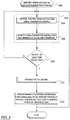
- FIG. 3 is a flow chart that illustrates an electric brake actuation overdrive-initiation process 300 suitable for use in connection with an aircraft electric brake system.
- the various tasks performed in connection with process 300 may be performed by software, hardware, firmware, or any combination thereof.
- the following description of process 300 may refer to elements mentioned above in connection with FIGS. 1-2 .
- portions of process 300 may be performed by different elements of the described system, e.g., a BSCU, an EBAC, or the like.
- process 300 may include any number of additional or alternative tasks, the tasks shown in FIG. 3 need not be performed in the illustrated order, and process 300 may be incorporated into a more comprehensive procedure, software or process having additional functionality not described in detail herein.
- the electric brake actuation overdrive system monitors (reference number 302) EBAs parameters by receiving EBAs parameters signals (task 304) from actuator sensors, and scans the EBA parameters signals (task 306) in a continuous or rapidly sampled manner for occurrence of a failure condition.
- the monitored EBA parameters signals may be, without limitation, an EBA electric current signal, an EBA voltage signal, an EBA position signal, an EBA load signal and the like.
- the failure condition may be a partial failure (e.g., loss of some clamping force) or a pending failure.
- Partial or pending failures may be detected by examination of motor-resolver feedback (no response or sluggish response to input commands); by load-cell feedback (no or inadequate load signal in response to input commands); and/or by measured motor-current level (e.g., high current may be indicative of motor and/or gear-train failure). If process 300 does not detect a failed EBA (inquiry task 308), the electric brake actuator motor controller leads back to task 302 to continue monitoring the EBAs parameters.
- EBAC disables the failed EBA (task 310) and proportionally overdrives remaining functional EBAs by an amount fully or partially equivalent to the lost clamping force of the failed EBA (task 312) on the same or other wheel-brakes (i.e. brakes mounted directly fore or aft from the failed EBA).
- disabling the failed EBA may be accomplished by inhibiting the motor current to the affected EBA via software control.
- a brake control signal may command the EBAs to release or apply no clamping force, it may command the EBAs to apply full clamping force, it may command the EBAs to apply some intermediate clamping force, or it may command the EBAs to apply more than the ordinary "full" clamping force.
- an electric brake system as described herein includes an electric brake actuation overdrive system feature that preserves braking performance with one or more deactivated EBAs.
- airplane braking performance is equivalent to a normal braking condition even with at least one failed or intentionally-deactivated EBA.
Landscapes
- Engineering & Computer Science (AREA)
- Transportation (AREA)
- Mechanical Engineering (AREA)
- Aviation & Aerospace Engineering (AREA)
- Regulating Braking Force (AREA)
- Valves And Accessory Devices For Braking Systems (AREA)
- Braking Systems And Boosters (AREA)
Claims (9)
- Elektrisches Bremssystem (100) für ein Luftfahrzeug, wobei das elektrische Bremssystem (100) aufweist:eine Radbremse (208), die ausgebildet ist, in Reaktion auf eine Klemmkraft ein Bremsmoment zu erzeugen;mehrere elektrische Bremsaktoren EBAs (206), die ausgebildet sind, die Klemmkraft für die Radbremse (208) aufzubringen;mehrere Sensoren (210), die mit den EBAs (206) verbunden und zum Erfassen von EBA-Parametern ausgebildet sind;eine EBA-Motorsteuerung (204), die mit den EBAs (206) verbunden ist, wobei die EBA-Motorsteuerung (204) ausgebildet ist zum:Überwachen der EBA-Parameter auf ein Auftreten einer Fehlerbedingung (302), wobei die EBA-Parameter eine EBA-Position umfassen;Erfassen zumindest eines fehlerhaften EBA auf Basis der Fehlerbedingung (308);Deaktivieren des zumindest einen fehlerhaften EBA (310); und proportionales Übersteuern der verbleibenden funktionierenden EBAs um einen Betrag, der der fehlenden Klemmkraft des zumindest einen fehlerhaften EBA (Schritt 312) ganz oder teilweise entspricht, an jeder Radbremse (208).
- System nach Anspruch 1, wobei die EBA-Parameter einen elektrischen EBA-Strom umfassen.
- System nach Anspruch 1, wobei die EBA-Parameter eine EBA-Spannung umfassen.
- System nach Anspruch 1, wobei die EBA-Parameter eine EBA-Last umfassen.
- System nach Anspruch 1, wobei die Aktormotorsteuerung (204) zum Überwachen der EBA-Parameter ausgebildet ist durch:Empfangen von EBA-Parametersignalen (304); undScannen der EBA-Parametersignale auf ein Auftreten der Fehlerbedingung (Schritt 306).
- Verfahren zum Bereitstellen einer elektrischen Bremsaktorübersteuerung für ein Luftfahrzeug, wobei das Verfahren umfasst:Überwachen von elektrischen Bremsaktor (EBA)-Parametern auf ein Auftreten einer Fehlerbedingung, wobei die EBA-Parameter eine EBA-Position umfassen;Erfassen zumindest eines fehlerhaften EBA auf Basis der Fehlerbedingung;Deaktivieren des zumindest einen fehlerhaften EBA; undproportionales Übersteuern der verbleibenden funktionierenden EBAs um einen Betrag, der der fehlenden Klemmkraft des zumindest einen fehlerhaften EBA ganz oder teilweise entspricht.
- Verfahren nach Anspruch 6, wobei der Überwachungsschritt ferner umfasst:Empfangen von EBA-Parametersignalen; undScannen der EBA-Parametersignale auf ein Auftreten der Fehlerbedingung.
- Verfahren nach Anspruch 7, wobei die EBA-Parametersignale ein elektrisches EBA-Stromsignal und ein EBA-Spannungssignal umfassen.
- Verfahren nach Anspruch 7, wobei die EBA-Parametersignale ein EBA-Lastsignal umfassen.
Applications Claiming Priority (2)
| Application Number | Priority Date | Filing Date | Title |
|---|---|---|---|
| US11/614,951 US20080154470A1 (en) | 2006-12-21 | 2006-12-21 | System and methods for an electric brake actuation overdrive feature in an aircraft electric brake system |
| PCT/US2007/088464 WO2008115306A2 (en) | 2006-12-21 | 2007-12-20 | A system and method for an electric brake actuation overdrive feature in an aircraft electric brake system |
Publications (2)
| Publication Number | Publication Date |
|---|---|
| EP2097300A2 EP2097300A2 (de) | 2009-09-09 |
| EP2097300B1 true EP2097300B1 (de) | 2017-09-06 |
Family
ID=39544101
Family Applications (1)
| Application Number | Title | Priority Date | Filing Date |
|---|---|---|---|
| EP07874418.2A Active EP2097300B1 (de) | 2006-12-21 | 2007-12-20 | Elektrisches Bremssystem für ein Flugzeug |
Country Status (4)
| Country | Link |
|---|---|
| US (1) | US20080154470A1 (de) |
| EP (1) | EP2097300B1 (de) |
| ES (1) | ES2650613T3 (de) |
| WO (1) | WO2008115306A2 (de) |
Families Citing this family (25)
| Publication number | Priority date | Publication date | Assignee | Title |
|---|---|---|---|---|
| US8244428B2 (en) * | 2006-05-10 | 2012-08-14 | The Boeing Company | Automatic fore-aft detection for an aircraft |
| GB0623804D0 (en) * | 2006-11-29 | 2007-01-10 | Dunlop Aerospace Ltd | A Braking system for an aircraft and a method of monitoring braking for an air |
| US7618100B2 (en) * | 2006-12-13 | 2009-11-17 | The Boeing Company | Braking interlock for an electric brake system of an aircraft |
| US7766431B2 (en) * | 2006-12-22 | 2010-08-03 | The Boeing Company | System and method for an autobrake function for an aircraft electric brake system |
| US9043050B2 (en) * | 2008-08-13 | 2015-05-26 | The Boeing Company | Programmable reverse thrust detent system and method |
| US20100292889A1 (en) * | 2009-05-14 | 2010-11-18 | Cahill Eric D | Brake operation built-in test equipment |
| US8393203B2 (en) * | 2010-03-08 | 2013-03-12 | Goodrich Corporation | Systems and methods for built in test equipment for a brake control system |
| US20110226569A1 (en) * | 2010-03-19 | 2011-09-22 | Hydro-Aire, Inc. | Electronic motor actuators brake inhibit for aircraft braking system |
| US8463462B2 (en) * | 2011-09-02 | 2013-06-11 | Goodrich Corporation | Systems and methods for braking system testing |
| FR3000004B1 (fr) * | 2012-12-21 | 2016-12-23 | Messier Bugatti Dowty | Procede de gestion du freinage d'un aeronef. |
| US9577850B2 (en) * | 2014-07-18 | 2017-02-21 | Goodrich Corporation | Control actuation smoothing |
| JP6584877B2 (ja) * | 2014-09-25 | 2019-10-02 | Ntn株式会社 | 電動ブレーキシステム |
| US9975530B2 (en) * | 2014-12-09 | 2018-05-22 | Goodrich Corporation | Method and system for electronic brake actuator detection |
| US9434369B1 (en) * | 2015-06-24 | 2016-09-06 | Goodrich Corporation | Systems and methods for detecting an uncommanded brake overdrive condition |
| US9771057B2 (en) | 2015-12-22 | 2017-09-26 | Goodrich Corporation | Staged method to detect brake fail conditions in brake control systems |
| US9663078B1 (en) * | 2015-12-28 | 2017-05-30 | Goodrich Corporation | Systems and methods for brake actuator operation sensor error compensation |
| US10093298B2 (en) * | 2016-01-08 | 2018-10-09 | Goodrich Corporation | Abnormal brake behavior detection |
| US10152050B2 (en) * | 2016-03-04 | 2018-12-11 | The Boeing Company | Apparatus and method for simulating a failure response in an electromechanical actuator |
| US10427665B2 (en) | 2016-03-21 | 2019-10-01 | Simmonds Precision Products, Inc. | Force feedback fault detection and accommodation for a multi-channel electric brake actuator controller |
| US10300896B2 (en) | 2016-10-10 | 2019-05-28 | Textron Innovations, Inc. | Brake system for aircraft |
| US11358710B2 (en) | 2018-02-23 | 2022-06-14 | The Boeing Company | Methods and apparatus for controlling landing gear retract braking |
| US10933982B2 (en) * | 2018-02-26 | 2021-03-02 | The Boeing Company | Methods and apparatus for controlling landing gear retract braking |
| US10829211B2 (en) * | 2018-04-23 | 2020-11-10 | Goodrich Corporation | Local digital conversion for force and position signals for electric actuation control |
| EP3725676A1 (de) * | 2019-04-16 | 2020-10-21 | Volocopter GmbH | Verfahren zur steuerung eines aktuatorsystems, notsteuerungssystem und flugzeug mit solch einem system |
| US11505167B2 (en) | 2020-01-06 | 2022-11-22 | The Boeing Company | Aircraft brake control systems |
Family Cites Families (9)
| Publication number | Priority date | Publication date | Assignee | Title |
|---|---|---|---|---|
| US6095293A (en) * | 1998-02-13 | 2000-08-01 | The B. F. Goodrich Company | Aircraft brake and method with electromechanical actuator modules |
| CA2378926C (en) * | 1999-07-14 | 2007-12-04 | Lawrence F. Corio | Braking system with power connection, distribution and redundancy |
| US6530625B2 (en) * | 1999-08-27 | 2003-03-11 | Alliedsignal Inc. | Electrically actuated brake with vibration damping |
| JP3872242B2 (ja) * | 1999-09-21 | 2007-01-24 | トヨタ自動車株式会社 | ブレーキ制御装置 |
| US6255941B1 (en) * | 2000-02-24 | 2001-07-03 | Indian Head Industries, Inc. | Brake monitoring system |
| US6604030B1 (en) * | 2000-06-06 | 2003-08-05 | Ozuna Holdings Incorporated | Single fault impervious integrated control and monitoring system |
| US20020167218A1 (en) * | 2001-05-09 | 2002-11-14 | Chubb Erik Christopher | Use of steering control to produce deceleration in a vehicle while remaining on a straight ground path |
| US6923510B2 (en) * | 2003-09-17 | 2005-08-02 | Delphi Technologies, Inc. | Control of brake-and steer-by-wire systems during brake failure |
| FR2864024B1 (fr) * | 2003-12-22 | 2006-04-07 | Messier Bugatti | Procede de gestion d'une architecture de systeme de freinage d'aeronef, et architecture de systeme de freinage faisant application |
-
2006
- 2006-12-21 US US11/614,951 patent/US20080154470A1/en not_active Abandoned
-
2007
- 2007-12-20 WO PCT/US2007/088464 patent/WO2008115306A2/en active Application Filing
- 2007-12-20 ES ES07874418.2T patent/ES2650613T3/es active Active
- 2007-12-20 EP EP07874418.2A patent/EP2097300B1/de active Active
Non-Patent Citations (1)
| Title |
|---|
| None * |
Also Published As
| Publication number | Publication date |
|---|---|
| EP2097300A2 (de) | 2009-09-09 |
| WO2008115306A3 (en) | 2009-01-08 |
| WO2008115306A2 (en) | 2008-09-25 |
| ES2650613T3 (es) | 2018-01-19 |
| US20080154470A1 (en) | 2008-06-26 |
Similar Documents
| Publication | Publication Date | Title |
|---|---|---|
| EP2097300B1 (de) | Elektrisches Bremssystem für ein Flugzeug | |
| US7618100B2 (en) | Braking interlock for an electric brake system of an aircraft | |
| EP2109558B1 (de) | Selbstbremsende sperre für ein elektrisches flugzeug-bremssystem | |
| CA2662703C (en) | Parking brake control for an aircraft having an electric brake system | |
| US8641154B2 (en) | Parking brake adjustment for an aircraft having an electric brake system | |
| US7766431B2 (en) | System and method for an autobrake function for an aircraft electric brake system | |
| CA2592917C (en) | Aircraft electrical brake control system architecture | |
| EP2463166B1 (de) | System und Verfahren zur Bereitstellung einer Bremsanzeige für elektrische Bremsen | |
| US6244675B1 (en) | Fail-safe brake system | |
| JP2010529917A5 (de) | ||
| US7524000B2 (en) | Brake status indicator control for an electric brake system of a vehicle | |
| CN115230654A (zh) | 用于车辆的制动系统 |
Legal Events
| Date | Code | Title | Description |
|---|---|---|---|
| PUAI | Public reference made under article 153(3) epc to a published international application that has entered the european phase |
Free format text: ORIGINAL CODE: 0009012 |
|
| 17P | Request for examination filed |
Effective date: 20090623 |
|
| AK | Designated contracting states |
Kind code of ref document: A2 Designated state(s): AT BE BG CH CY CZ DE DK EE ES FI FR GB GR HU IE IS IT LI LT LU LV MC MT NL PL PT RO SE SI SK TR |
|
| 17Q | First examination report despatched |
Effective date: 20091208 |
|
| DAX | Request for extension of the european patent (deleted) | ||
| GRAP | Despatch of communication of intention to grant a patent |
Free format text: ORIGINAL CODE: EPIDOSNIGR1 |
|
| INTG | Intention to grant announced |
Effective date: 20170324 |
|
| GRAS | Grant fee paid |
Free format text: ORIGINAL CODE: EPIDOSNIGR3 |
|
| GRAA | (expected) grant |
Free format text: ORIGINAL CODE: 0009210 |
|
| AK | Designated contracting states |
Kind code of ref document: B1 Designated state(s): AT BE BG CH CY CZ DE DK EE ES FI FR GB GR HU IE IS IT LI LT LU LV MC MT NL PL PT RO SE SI SK TR |
|
| REG | Reference to a national code |
Ref country code: GB Ref legal event code: FG4D |
|
| REG | Reference to a national code |
Ref country code: CH Ref legal event code: EP Ref country code: AT Ref legal event code: REF Ref document number: 925511 Country of ref document: AT Kind code of ref document: T Effective date: 20170915 |
|
| REG | Reference to a national code |
Ref country code: IE Ref legal event code: FG4D |
|
| REG | Reference to a national code |
Ref country code: DE Ref legal event code: R096 Ref document number: 602007052325 Country of ref document: DE |
|
| REG | Reference to a national code |
Ref country code: FR Ref legal event code: PLFP Year of fee payment: 11 |
|
| REG | Reference to a national code |
Ref country code: NL Ref legal event code: MP Effective date: 20170906 |
|
| REG | Reference to a national code |
Ref country code: ES Ref legal event code: FG2A Ref document number: 2650613 Country of ref document: ES Kind code of ref document: T3 Effective date: 20180119 |
|
| REG | Reference to a national code |
Ref country code: LT Ref legal event code: MG4D |
|
| PG25 | Lapsed in a contracting state [announced via postgrant information from national office to epo] |
Ref country code: LT Free format text: LAPSE BECAUSE OF FAILURE TO SUBMIT A TRANSLATION OF THE DESCRIPTION OR TO PAY THE FEE WITHIN THE PRESCRIBED TIME-LIMIT Effective date: 20170906 Ref country code: FI Free format text: LAPSE BECAUSE OF FAILURE TO SUBMIT A TRANSLATION OF THE DESCRIPTION OR TO PAY THE FEE WITHIN THE PRESCRIBED TIME-LIMIT Effective date: 20170906 Ref country code: SE Free format text: LAPSE BECAUSE OF FAILURE TO SUBMIT A TRANSLATION OF THE DESCRIPTION OR TO PAY THE FEE WITHIN THE PRESCRIBED TIME-LIMIT Effective date: 20170906 |
|
| REG | Reference to a national code |
Ref country code: AT Ref legal event code: MK05 Ref document number: 925511 Country of ref document: AT Kind code of ref document: T Effective date: 20170906 |
|
| PG25 | Lapsed in a contracting state [announced via postgrant information from national office to epo] |
Ref country code: BG Free format text: LAPSE BECAUSE OF FAILURE TO SUBMIT A TRANSLATION OF THE DESCRIPTION OR TO PAY THE FEE WITHIN THE PRESCRIBED TIME-LIMIT Effective date: 20171206 Ref country code: GR Free format text: LAPSE BECAUSE OF FAILURE TO SUBMIT A TRANSLATION OF THE DESCRIPTION OR TO PAY THE FEE WITHIN THE PRESCRIBED TIME-LIMIT Effective date: 20171207 Ref country code: LV Free format text: LAPSE BECAUSE OF FAILURE TO SUBMIT A TRANSLATION OF THE DESCRIPTION OR TO PAY THE FEE WITHIN THE PRESCRIBED TIME-LIMIT Effective date: 20170906 |
|
| PG25 | Lapsed in a contracting state [announced via postgrant information from national office to epo] |
Ref country code: NL Free format text: LAPSE BECAUSE OF FAILURE TO SUBMIT A TRANSLATION OF THE DESCRIPTION OR TO PAY THE FEE WITHIN THE PRESCRIBED TIME-LIMIT Effective date: 20170906 |
|
| PG25 | Lapsed in a contracting state [announced via postgrant information from national office to epo] |
Ref country code: RO Free format text: LAPSE BECAUSE OF FAILURE TO SUBMIT A TRANSLATION OF THE DESCRIPTION OR TO PAY THE FEE WITHIN THE PRESCRIBED TIME-LIMIT Effective date: 20170906 Ref country code: CZ Free format text: LAPSE BECAUSE OF FAILURE TO SUBMIT A TRANSLATION OF THE DESCRIPTION OR TO PAY THE FEE WITHIN THE PRESCRIBED TIME-LIMIT Effective date: 20170906 Ref country code: PL Free format text: LAPSE BECAUSE OF FAILURE TO SUBMIT A TRANSLATION OF THE DESCRIPTION OR TO PAY THE FEE WITHIN THE PRESCRIBED TIME-LIMIT Effective date: 20170906 |
|
| PG25 | Lapsed in a contracting state [announced via postgrant information from national office to epo] |
Ref country code: SK Free format text: LAPSE BECAUSE OF FAILURE TO SUBMIT A TRANSLATION OF THE DESCRIPTION OR TO PAY THE FEE WITHIN THE PRESCRIBED TIME-LIMIT Effective date: 20170906 Ref country code: AT Free format text: LAPSE BECAUSE OF FAILURE TO SUBMIT A TRANSLATION OF THE DESCRIPTION OR TO PAY THE FEE WITHIN THE PRESCRIBED TIME-LIMIT Effective date: 20170906 Ref country code: IS Free format text: LAPSE BECAUSE OF FAILURE TO SUBMIT A TRANSLATION OF THE DESCRIPTION OR TO PAY THE FEE WITHIN THE PRESCRIBED TIME-LIMIT Effective date: 20180106 Ref country code: EE Free format text: LAPSE BECAUSE OF FAILURE TO SUBMIT A TRANSLATION OF THE DESCRIPTION OR TO PAY THE FEE WITHIN THE PRESCRIBED TIME-LIMIT Effective date: 20170906 |
|
| REG | Reference to a national code |
Ref country code: DE Ref legal event code: R097 Ref document number: 602007052325 Country of ref document: DE |
|
| PLBE | No opposition filed within time limit |
Free format text: ORIGINAL CODE: 0009261 |
|
| STAA | Information on the status of an ep patent application or granted ep patent |
Free format text: STATUS: NO OPPOSITION FILED WITHIN TIME LIMIT |
|
| PG25 | Lapsed in a contracting state [announced via postgrant information from national office to epo] |
Ref country code: DK Free format text: LAPSE BECAUSE OF FAILURE TO SUBMIT A TRANSLATION OF THE DESCRIPTION OR TO PAY THE FEE WITHIN THE PRESCRIBED TIME-LIMIT Effective date: 20170906 |
|
| REG | Reference to a national code |
Ref country code: CH Ref legal event code: PL |
|
| 26N | No opposition filed |
Effective date: 20180607 |
|
| PG25 | Lapsed in a contracting state [announced via postgrant information from national office to epo] |
Ref country code: SI Free format text: LAPSE BECAUSE OF FAILURE TO SUBMIT A TRANSLATION OF THE DESCRIPTION OR TO PAY THE FEE WITHIN THE PRESCRIBED TIME-LIMIT Effective date: 20170906 |
|
| REG | Reference to a national code |
Ref country code: IE Ref legal event code: MM4A |
|
| PG25 | Lapsed in a contracting state [announced via postgrant information from national office to epo] |
Ref country code: LU Free format text: LAPSE BECAUSE OF NON-PAYMENT OF DUE FEES Effective date: 20171220 Ref country code: MT Free format text: LAPSE BECAUSE OF NON-PAYMENT OF DUE FEES Effective date: 20171220 |
|
| REG | Reference to a national code |
Ref country code: BE Ref legal event code: MM Effective date: 20171231 |
|
| PG25 | Lapsed in a contracting state [announced via postgrant information from national office to epo] |
Ref country code: IE Free format text: LAPSE BECAUSE OF NON-PAYMENT OF DUE FEES Effective date: 20171220 |
|
| PG25 | Lapsed in a contracting state [announced via postgrant information from national office to epo] |
Ref country code: CH Free format text: LAPSE BECAUSE OF NON-PAYMENT OF DUE FEES Effective date: 20171231 Ref country code: LI Free format text: LAPSE BECAUSE OF NON-PAYMENT OF DUE FEES Effective date: 20171231 Ref country code: BE Free format text: LAPSE BECAUSE OF NON-PAYMENT OF DUE FEES Effective date: 20171231 |
|
| PG25 | Lapsed in a contracting state [announced via postgrant information from national office to epo] |
Ref country code: MC Free format text: LAPSE BECAUSE OF FAILURE TO SUBMIT A TRANSLATION OF THE DESCRIPTION OR TO PAY THE FEE WITHIN THE PRESCRIBED TIME-LIMIT Effective date: 20170906 Ref country code: HU Free format text: LAPSE BECAUSE OF FAILURE TO SUBMIT A TRANSLATION OF THE DESCRIPTION OR TO PAY THE FEE WITHIN THE PRESCRIBED TIME-LIMIT; INVALID AB INITIO Effective date: 20071220 |
|
| PG25 | Lapsed in a contracting state [announced via postgrant information from national office to epo] |
Ref country code: CY Free format text: LAPSE BECAUSE OF NON-PAYMENT OF DUE FEES Effective date: 20170906 |
|
| REG | Reference to a national code |
Ref country code: DE Ref legal event code: R082 Ref document number: 602007052325 Country of ref document: DE Representative=s name: MAIER, LL.M., MICHAEL C., DE Ref country code: DE Ref legal event code: R082 Ref document number: 602007052325 Country of ref document: DE Representative=s name: BOULT WADE TENNANT LLP, DE |
|
| REG | Reference to a national code |
Ref country code: DE Ref legal event code: R082 Ref document number: 602007052325 Country of ref document: DE Representative=s name: BOULT WADE TENNANT LLP, DE |
|
| PG25 | Lapsed in a contracting state [announced via postgrant information from national office to epo] |
Ref country code: PT Free format text: LAPSE BECAUSE OF FAILURE TO SUBMIT A TRANSLATION OF THE DESCRIPTION OR TO PAY THE FEE WITHIN THE PRESCRIBED TIME-LIMIT Effective date: 20170906 |
|
| P01 | Opt-out of the competence of the unified patent court (upc) registered |
Effective date: 20230516 |
|
| PGFP | Annual fee paid to national office [announced via postgrant information from national office to epo] |
Ref country code: GB Payment date: 20231227 Year of fee payment: 17 |
|
| PGFP | Annual fee paid to national office [announced via postgrant information from national office to epo] |
Ref country code: TR Payment date: 20231207 Year of fee payment: 17 Ref country code: IT Payment date: 20231220 Year of fee payment: 17 Ref country code: FR Payment date: 20231227 Year of fee payment: 17 |
|
| PGFP | Annual fee paid to national office [announced via postgrant information from national office to epo] |
Ref country code: ES Payment date: 20240102 Year of fee payment: 17 |
|
| PGFP | Annual fee paid to national office [announced via postgrant information from national office to epo] |
Ref country code: DE Payment date: 20231229 Year of fee payment: 17 |