EP2461844B1 - Vorrichtung und verfahren zur erkennung von blut oder blutbestandteilen im flüssigkeitssystem einer vorrichtung zur extrakorporalen blutbehandlung - Google Patents
Vorrichtung und verfahren zur erkennung von blut oder blutbestandteilen im flüssigkeitssystem einer vorrichtung zur extrakorporalen blutbehandlung Download PDFInfo
- Publication number
- EP2461844B1 EP2461844B1 EP10747579.0A EP10747579A EP2461844B1 EP 2461844 B1 EP2461844 B1 EP 2461844B1 EP 10747579 A EP10747579 A EP 10747579A EP 2461844 B1 EP2461844 B1 EP 2461844B1
- Authority
- EP
- European Patent Office
- Prior art keywords
- intensity
- component
- blood
- quotient
- entry
- Prior art date
- Legal status (The legal status is an assumption and is not a legal conclusion. Google has not performed a legal analysis and makes no representation as to the accuracy of the status listed.)
- Not-in-force
Links
Images


Classifications
-
- A—HUMAN NECESSITIES
- A61—MEDICAL OR VETERINARY SCIENCE; HYGIENE
- A61M—DEVICES FOR INTRODUCING MEDIA INTO, OR ONTO, THE BODY; DEVICES FOR TRANSDUCING BODY MEDIA OR FOR TAKING MEDIA FROM THE BODY; DEVICES FOR PRODUCING OR ENDING SLEEP OR STUPOR
- A61M1/00—Suction or pumping devices for medical purposes; Devices for carrying-off, for treatment of, or for carrying-over, body-liquids; Drainage systems
- A61M1/14—Dialysis systems; Artificial kidneys; Blood oxygenators ; Reciprocating systems for treatment of body fluids, e.g. single needle systems for hemofiltration or pheresis
- A61M1/16—Dialysis systems; Artificial kidneys; Blood oxygenators ; Reciprocating systems for treatment of body fluids, e.g. single needle systems for hemofiltration or pheresis with membranes
- A61M1/1692—Detection of blood traces in dialysate
-
- G—PHYSICS
- G01—MEASURING; TESTING
- G01N—INVESTIGATING OR ANALYSING MATERIALS BY DETERMINING THEIR CHEMICAL OR PHYSICAL PROPERTIES
- G01N21/00—Investigating or analysing materials by the use of optical means, i.e. using sub-millimetre waves, infrared, visible or ultraviolet light
- G01N21/17—Systems in which incident light is modified in accordance with the properties of the material investigated
- G01N21/25—Colour; Spectral properties, i.e. comparison of effect of material on the light at two or more different wavelengths or wavelength bands
- G01N21/251—Colorimeters; Construction thereof
-
- G—PHYSICS
- G01—MEASURING; TESTING
- G01N—INVESTIGATING OR ANALYSING MATERIALS BY DETERMINING THEIR CHEMICAL OR PHYSICAL PROPERTIES
- G01N33/00—Investigating or analysing materials by specific methods not covered by groups G01N1/00 - G01N31/00
- G01N33/48—Biological material, e.g. blood, urine; Haemocytometers
- G01N33/483—Physical analysis of biological material
- G01N33/487—Physical analysis of biological material of liquid biological material
- G01N33/49—Blood
-
- A—HUMAN NECESSITIES
- A61—MEDICAL OR VETERINARY SCIENCE; HYGIENE
- A61M—DEVICES FOR INTRODUCING MEDIA INTO, OR ONTO, THE BODY; DEVICES FOR TRANSDUCING BODY MEDIA OR FOR TAKING MEDIA FROM THE BODY; DEVICES FOR PRODUCING OR ENDING SLEEP OR STUPOR
- A61M2205/00—General characteristics of the apparatus
- A61M2205/18—General characteristics of the apparatus with alarm
-
- A—HUMAN NECESSITIES
- A61—MEDICAL OR VETERINARY SCIENCE; HYGIENE
- A61M—DEVICES FOR INTRODUCING MEDIA INTO, OR ONTO, THE BODY; DEVICES FOR TRANSDUCING BODY MEDIA OR FOR TAKING MEDIA FROM THE BODY; DEVICES FOR PRODUCING OR ENDING SLEEP OR STUPOR
- A61M2205/00—General characteristics of the apparatus
- A61M2205/33—Controlling, regulating or measuring
- A61M2205/3306—Optical measuring means
- A61M2205/3313—Optical measuring means used specific wavelengths
Definitions
- the invention relates to an apparatus and a method for detecting blood or blood constituents in the fluid system of an extracorporeal blood treatment apparatus comprising a dialyzer or filter divided into a first chamber and a second chamber by a semipermeable membrane, the first chamber being part of the extracorporeal blood circuit and the second chamber is part of the fluid system of the extracorporeal blood treatment device.
- hemodialysis the patient's blood is purified in an extracorporeal blood circuit that includes a dialyzer.
- the dialyzer has a blood chamber and a dialysis fluid chamber, which are separated by a semipermeable membrane.
- the dialysis fluid chamber is traversed by dialysis fluid, whereby substances are transported through the membrane due to the diffusion between the dialysis fluid and the blood, the dialysis fluid chamber of the dialyzer does not flow through dialysis fluid during hemofiltration (HF).
- Hemofiltration (HF) effectively removes certain substances due to convection through the membrane of the filter.
- a combination of both methods is hemodiafiltration (HDF).
- the known blood leak detector has a housing in which a transparent hose is inserted.
- a light emitter and a light receiver on both sides of the inserted hose.
- hemoglobin or its constituents can enter into the dialysis fluid due to hemolysis in an extracorporeal blood treatment.
- Hemolysis is the dissolution (destruction) of the erythrocytes (red blood cells) of the blood.
- the erythrocytes consist mainly of the oxygen binding protein hemoglobin, which gives the red blood to the erythrocytes and thus to the blood. When hemolysis occurs, the hemoglobin is released.
- Hemolysis may occur in extracorporeal blood treatment, for example due to mechanical stress on the blood due to shear flow. Such shear flows occur, inter alia, when a blood-carrying tubing of the tubing system of the blood treatment device is bent. Hemolysis may also be systemic due to the patient.
- Hemoglobin in extracorporeal blood treatment, may diffuse from the blood side of the dialyzer through the semipermeable membrane to the dialysate side. Therefore, the hemoglobin can be detected in the blood by the optical measuring methods known in the art.
- a disadvantage is that with the known optical measuring method, it can not be distinguished between an entry of blood as a result of a defect in the dialyzer or filter or the entry of hemoglobin as a blood component as a result of hemolysis.
- a defect of the dialyzer or filter or hemolysis but are to introduce different measures. For example, in the case of a membrane rupture, the dialyzer must be exchanged, while in the case of hemolysis the user must be advised to initiate suitable countermeasures, for example to change the tube system or at least to free it from the kink.
- the monitoring devices generally used in extracorporeal blood treatment for the detection of blood ingress or hemolysis are based on the spectroscopic evaluation of the red and green portion of the light. In this wavelength range, however, it is not possible to distinguish between blood and hemoglobin.
- the US 2007/0259436 A1 describes a method for detecting hemoglobin in blood in which light having a wavelength of 390 to 460 nm passes through a sample. The change in light intensity is determined for two or more wavelengths.
- a method for detecting a hemolysis in which the decrease in the intensity of the blue component of light is taken into account is also known from US Pat JP 62000838A known.
- the invention is based on the object to provide a device that allows entry of blood or blood components in the fluid system of the extracorporeal blood treatment device to make a decision on the initiation of targeted countermeasures.
- the device according to the invention for detecting blood or blood components in the fluid system of an extracorporeal blood treatment device is a device for distinguishing between the entry of blood into the fluid system due to a defect of the dialyzer or filter, for example a rupture of the semipermeable membrane of the dialyzer or filter, and entry hemoglobin is formed into the fluid system due to hemolysis, whereby a defect of the dialyzer or filter or hemolysis is detected based on the change in the intensity of light passing through the fluid in the fluid system.
- the quotient of the intensity of the red or green portion of the light emerging from the liquid and the intensity of the blue portion of the emergent light increases when hemolyzed blood does not enter the dialysis fluid. Also, the quotient of the intensity of the red portion and the green portion of the light exiting the liquid increases when non-hemolyzed blood enters the dialysis fluid.
- the quotient of the intensity of the red component and the blue component or the quotient of the intensity of the red component and the green component increase.
- the quotient of the green component and the blue component does not change or does not change significantly when hemolyzed blood enters.
- a distinction between the entry of hemolyzed and non-hemolyzed blood can be made by evaluating the ratio of red and blue in the light exiting the fluid. It has been shown that the quotient of the red portion and blue portion increases at the entry of non-hemolyzed blood strength than the entry of hemolyzed blood. Also, a distinction between the entry of hemolyzed and non-hemolyzed blood can be made by evaluating the ratio of the green portion and the blue portion of the light exiting the fluid, as there is a significant increase in the quotient only at the entry of non-hemolyzed blood shows.
- a preferred embodiment of the invention envisages between the entry of blood into the fluid system due to a defect of the dialyzer or filter and the entry of hemoglobin into the fluid system due to hemolysis based on the change in intensity of at least the blue portion of the light exiting the fluid to distinguish.
- the blue component it is also possible to evaluate further components of the light, for example the red component and / or the green component. It has been shown that the evaluation of the blue component allows a reliable differentiation between blood and the blood component hemoglobin in the dialysis fluid.
- Another particularly preferred embodiment provides for the evaluation of both the blue component and the red component.
- the intensity of the blue portion of the light emerging from the liquid on the one hand and the intensity of the red portion of the light emerging from the liquid on the other hand are determined.
- the intensity of the red component is compared with the intensity of the blue component. Since the changes in light intensity of both the blue and red components are evaluated and correlated, it is safe to distinguish between blood and hemoglobin.
- the intensity of the light entering the liquid plays no role for the device according to the invention and the method according to the invention, since two different color components are set in relation. Therefore, the device according to the invention and the method according to the invention are insensitive to variations in the intensity of the light source.
- the quotient of the intensity of the red component and the intensity of the blue component is compared with a predetermined limit value and / or the quotient of the intensity of the green component and the intensity of the blue component is compared with a predetermined limit value.
- An entry of hemoglobin as a result of hemolysis is then closed when the quotient is less than or equal to the predetermined limit.
- the quotient is greater than the predefined limit value, the entry of blood is concluded, for example due to a rupture of the membrane.
- a limit only a single value can be specified. It But it is also possible to set several individual values for different queries as the limit value.
- a particularly preferred embodiment initially provides for the calculation of the quotient of the red fraction and the green component of the light emerging from the liquid for the detection of the entry of hemolyzed blood or non-hemolyzed blood into the dialysis fluid, but not between the entry of hemolyzed blood or non-hemolyzed blood to be able to distinguish. Only when hemolyzed blood or non-hemolyzed blood is detected, the quotient of the red and blue portion and / or from the green and blue portion to distinguish between a defect of the dialyzer or filter or hemolysis is determined.
- not only the intensity of the light exiting the liquid, but also the intensity of the light entering the liquid is monitored.
- the monitoring of the intensity of the light entering the liquid allows the detection of an accident.
- the means for transmitting light for example an LED
- the device according to the invention has means for emitting light entering the liquid in the liquid system and means for receiving light emerging from the liquid in the liquid system.
- the device has an evaluation unit for evaluating the intensity of the in the Liquid entering and emerging from the liquid light.
- the means for emitting light is a light source emitting white light, for example a white light emitting LED or a white light emitting RGB LED, while the means for receiving light is a light sensor having different color components of the light receives.
- the measuring apparatus has a simpler structure than a measuring apparatus, in which a plurality of light sources are provided, for example, a blue, red and green light source, and a plurality of light sensors are provided which receive, for example, blue, red and green light.
- a light source that emits nonspecific light proves to be advantageous because the measurement result can be less affected by shifts in the spectrum of light emitted by individual light sources having a narrow wavelength band.
- Another particularly preferred embodiment provides for an adaptation of the predetermined limit value or the predetermined limit values to the patient. This makes it possible to distinguish between the entry of blood or hemoglobin into the fluid system even in patients suffering from systemic hemolysis.
- the predetermined limit can be adjusted accordingly, so that not alone due to the increased proportion of hemoglobin in the blood due to a systemic hemolysis on the entry of hemoglobin in the dialysis fluid is closed is due to damage to the blood, for example, by a bent blood leading tubing.
- a set of adjusted limit values can be determined and specified.
- the adaptation of the predetermined limit value or the limit values is preferably carried out on the basis of patient-specific data, preferably on a Input unit can be entered.
- the predetermined limit value is determined as a function of patient-specific data, which are obtained on the basis of a reference measurement. For example, it is possible to provide a reference measurement at a time before or at the beginning or during the blood treatment, in which a hemolysis, for example due to the kinking of a hose line, is not assumed. Deviations from this threshold may then indicate the onset of hemoglobin due to blood damage.
- an optical and / or acoustic and / or tactile signal may be given to initiate appropriate countermeasures.
- the blood treatment can be interrupted immediately when blood enters. It is also possible that a control signal for an intervention in the machine control is generated in order to initiate countermeasures automatically.
- the result of the monitoring is preferably displayed on a screen, which may be a so-called touch screen.
- a screen which may be a so-called touch screen.
- the recommended countermeasures are displayed, for example by an appropriate text and / or corresponding symbols. For example, it may be necessary to replace the hose line system or the dialyzer.
- Fig. 1 shows in a highly simplified schematic representation of an embodiment of the relevant for the invention components of an extracorporeal blood treatment device that can be operated as a hemodialysis and / or hemofiltration device. Therefore, the extracorporeal blood treatment device will hereinafter also be referred to as a hemodiafiltration device.
- the hemodiafiltration device has a dialyzer or filter 1 which is separated by a semipermeable membrane 2 into a blood chamber 3 and a dialysis fluid chamber 4.
- the inlet 3a of the blood chamber is connected to one end of an arterial blood supply line 5 into which a blood pump 6 is connected, while the outlet 3b of the blood chamber is connected to one end of a venous blood return line 7 into which a drip chamber 8 is connected.
- At the other ends of the arterial and venous blood lines 5, 7 are the arterial and venous cannulae (not shown) for connection to the patient.
- This part of the fluid system constitutes the extracorporeal blood circulation I of the Hemodiafiltration device.
- the blood lines 5, 7 are hose lines of a single use hose line system, which is inserted into the blood treatment device.
- the fluid system II of the hemodiafiltration device comprises a device 9 for providing fresh dialysis fluid, which is connected via a dialysis fluid supply line 10 to the inlet 4a of the dialysis fluid chamber 4 of the dialyzer 1 or filter. From the outlet 4b of the dialysis fluid chamber 4 of the dialyzer 1 or filter, a dialysis fluid return line 11 leaves, which leads to an outlet 12.
- the hemodiafiltration device has a substituate source 14, from which a substituate line 15 into which a substituate pump 16 is connected leads to the venous drip chamber 8.
- a predetermined amount of substitution fluid from the substituate source can be supplied to the extracorporeal blood circuit 1 if fluid is withdrawn from the extracorporeal blood circuit I via the dialyzer 1.
- the hemodiafiltration device further comprises a central control and computing unit 17, which is connected via control lines 6 ', 13', 16 'to the blood pump 6, the dialysis fluid pump 13 and the substituate pump 16.
- the control and computing unit 17 sends control commands to the individual components and receives data about their operating states from the components.
- the device according to the invention for detecting blood or blood constituents in the fluid system of the extracorporeal blood treatment device will now be described.
- the device according to the invention for detecting blood or blood components may form an independent unit or be part of the blood treatment device.
- the device according to the invention is part of the blood treatment device.
- the device according to the invention can make use of the parts which are already present in the known extracorporeal blood treatment devices.
- the device according to the invention can make use of the central control and computing unit of the blood treatment apparatus in order to evaluate the measured data obtained.
- the device of the invention can use the display unit and the input unit of the blood treatment device.
- a separate evaluation unit may also be provided for the inventive device, a separate display unit or input unit may be present.
- the device for detecting blood or hemoglobin has a light source 21 A, such as an LED, and a light sensor 21 B, which are arranged opposite to each other.
- Light source 21A and light sensor 21B constitute a measuring arrangement 21 for measuring the change in the intensity of light resulting from the liquid in liquid system II, i. Dialysis fluid emerges. Since the dialysis fluid lines 10, 11 are transparent tubing, the light can be coupled through the tubing into the dialysis fluid and decoupled from the dialysis fluid.
- the measuring arrangement 21 is arranged on the dialysis fluid return line 11, in particular in the section of the dialysis fluid return line 11, downstream of the dialysis fluid chamber 4 of the dialyzer 1 or filter and upstream of the dialysis fluid pump 13.
- the measurement can be carried out either on a measuring chamber intended for single use or on a permanently installed measuring chamber of the hose line.
- a measuring chamber a cuvette can be used.
- the measuring arrangement may also have an input-side light sensor 21 C, which measures the light emitted by the light source 21 A light.
- a shut-off device 18 Downstream of the drip chamber 8 is located on the venous blood line 7 a shut-off device 18 for shutting off the blood line 7.
- the obturator 18, in particular an electromagnetically operable hose clamp, is connected via a control line 18 'to the control and computing unit 17.
- the device for detecting blood or blood components has an evaluation unit 20, which is connected via a data line 20 'to the central control and computing unit 17 of the hemodiafiltration device.
- the evaluation unit 20 can also be part of the control and computing unit 17.
- the evaluation unit receives the signals of the output-side light sensor 21 B via a data line 21 'and the signals of the input-side light sensor 21C of the measuring arrangement 21 via a data line 21 ".
- the evaluation unit 20 may have a control unit which has a control unit which is dependent on the light sensor 2 1 connected to the output side B measured intensity of the light emitted from the light source 21 A, the light source such that the light intensity remains constant regardless of the ambient conditions.
- the result of the monitoring is signaled by a signal unit 22 which is connected to the evaluation unit 20 via a data line 22 '.
- the signal unit 22 has a screen 22A for displaying symbols or text and an alarm generator 22B for generating an audible or tactile alarm.
- the input unit 23 may be also act as a so-called touch screen, which serves as a screen of the signal unit.
- the light source 21A of the measuring arrangement 21 emits white light which contains the color components red, green and blue with a specific intensity I 0 .
- the light source 21 A is connected via a control line 21 A 'to the central control and computing unit 17, so that the intensity I 0 of the light from the control and computing unit 17 can be specified.
- the light sensor 21B receives the light passing through the dialyzing fluid (filtrate) from the light source 21 A.
- the light sensor is a sensor that can evaluate the intensity I 1 of three color components red, green and blue (RGB).
- the photosensitive surface of the sensor is formed by a plurality of identical photodiodes arranged in rows and columns. Each photodiode is associated with a color filter. For the evaluation of the red component, a red color filter is provided, for the evaluation of the green component a green color filter and for the evaluation of the blue component of the light a blue color filter.
- Fig. 2 shows the checkered arrangement of the photodiodes with the color filters.
- the color filters are marked R (red), G (green) and B (blue).
- the light sensor 21 B provides an electrical output signal that contains information about the intensity of the red, green and blue portion of the light.
- Fig. 3 shows a schematic representation of the relative sensitivity of the sensor for the individual color components blue, green and red. Since the light sensor not only a single measurement point, but a measuring field maps, the sensor 1 provides an integrated over the photosensitive surface output signal.
- the light sensor can be, for example, a "Programmable Color Light-To-Frequency Converter TCS230" manufactured by TAOS (Texas Adv. Optoelectronic Solutions Inc., Piano, Texas, USA) or a “Digital Color Sensor S9706 “of the company Hamamatsu (Hamamatsu Photonics KK, Japan) or the like. Construction and function of the two sensors are described in detail in the data sheets of the manufacturer.
- the evaluation unit 20 receives the three color components red, green and blue containing output signal S of the output side light sensor 21B of the measuring device 21.
- the output signal of the sensor in the three individual signals for the color components red, green and blue (RGB) is decomposed.
- the amount of the individual signals (signal strength) is proportional to the intensity I 1 of the light emerging from the dialysis fluid (filtrate).
- the intensity I 0 of the light entering the dialysis fluid (filtrate) is determined by the light source 21 A and measured with the input-side light sensor 21C.
- the evaluation unit 20 now determines the quotient R / B from the intensity I 1 of the red component R of the light emerging from the liquid, ie the amount of the individual signal for the red component, and the intensity I 1 of the blue component B of the light emerging from the liquid, ie the amount of the single signal for the blue component.
- the evaluation unit can calculate the quotient R / G from the intensity I 1 of the red component and the green component, ie the quotient of the individual signals of the red and green component.
- the evaluation unit calculates the quotient G / B of the intensity I 1 of the green component and the blue component. All quotients are stored in an internal memory of the evaluation unit.
- the measurement can take place at predetermined time intervals or continuously. It is also possible to perform reference measurements at certain times, for example before the treatment, in order to be able to compare the current values with the reference values.
- the reference measurements can also be carried out cyclically, for example using a bypass bypassing the dialyzer or filter.
- the bypass for bypassing the dialyzer for the reference measurements comprises a bypass line 24 which leaves the dialysis fluid supply line 10 upstream of the dialysis fluid chamber 4 and leads to the dialysis fluid discharge line 11 downstream of the dialysis fluid chamber.
- a shut-off device 25 for opening and closing the bypass line and in the portion of the dialysis fluid 10 between the bypass line 24 and the Dialysing fluid chamber 4 is a shut-off device 26 for separating the dialysis fluid.
- the two shut-off elements 25, 26 are connected via control lines 25 ', 26' to the central control and computing unit 17.
- the control unit opens the obturator 24 and closes the obturator 25. Otherwise, the obturator 24 are closed and the obturator 25 is opened.
- Fig. 4 shows schematically the characteristic curves of the extinction for intact blood in the dialysate on the one hand and for hemolyzed blood in the dialysate on the other hand and the relative sensitivity of the sensor as a function of the wavelength. It can be seen that in the range of blue to green light there are considerable differences for intact blood and hemolyzed blood because the hemolyzed blood introduces free hemoglobin into the dialysate. In the area of green to red light, on the other hand, there are hardly any differences. The count of extinction for intact blood in the dialysate differs among other things in the region of the blue spectrum from the count of extinction for the hemolyzed blood in the dialysate.
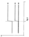
- Fig. 5 shows the magnitude of the quotient of the individual signals S of the color sensor for the individual color components of the light ROT / BLUE (R / B), RED / GREEN (R / G), GREEN / BLUE (G / B) as a function of the time before entry (t ⁇ t 1 ) and after entry (t> t 1 ) of hemolyzed blood into the dialysate. It can be seen that the addition of hemoglobin significantly increases the red / blue quotient (RED / BLUE) quotient and the red / green quotient (RED / GREEN) quotient, while the magnitude of the quotient green and blue (GREEN / BLUE) changed little or not significantly.
- Fig. 6 shows the case of non-hemolyzed blood entering the dialysate. It turns out that the amount of all quotients (RED / BLUE, RED / GREEN and GREEN / BLUE) increases significantly with the entry of non-hemolyzed blood.
- a comparison of Figures 5 and 6 shows that the entry of non-hemolyzed blood ( Fig. 6 ) leads to a greater increase in the amount of the red and blue ratio (RED / BLUE) than the entry of hemolysed blood ( Fig. 5 ). While with the entry of hemolyzed blood the amount of the quotient of the green and Blue component (GREEN / BLUE) remains virtually unchanged ( Fig.
- the difference between the increase in the red / blue ratio (RED / BLUE) ratio of haemolysed blood and non-hemolyzed blood and the difference between the green / blue ratio (GREEN / BLUE) of haemolysed and non-hemolyzed Blood is in FIG. 6 denoted by ⁇ .
- the evaluation unit 20 compares the quotient of the red and blue component (RED / BLUE) with a predetermined limit, which can be changed depending on the method. In this embodiment, only the quotient R / B of the red and blue components, which is compared with the predetermined limit, needs to be calculated. If the quotient of the red and blue component (RED / BLUE) is above the predefined limit value, the evaluation unit 20 concludes the entry of non-hemolyzed blood, for example due to a membrane rupture (FIG. Fig. 6 ), while the evaluation unit concludes the entry of hemolyzed blood, for example, as a result of blood damage, for example due to a kinked tubing or a systemic hemolysis ( Fig. 5 ), when the quotient of the red and blue component (RED / BLUE) is less than or equal to the specified limit value.
- a membrane rupture for example due to a membrane rupture
- hemolyzed blood for example, as a result of blood damage, for example due
- the evaluation unit 20 does not calculate the quotients of the red and blue components but the quotients of the green and blue components.
- the evaluation unit concludes that non-hemolyzed blood ( Fig. 6 ), when the quotient of the green and blue component (GREEN / BLUE) is greater than the predetermined limit, while the evaluation unit concludes that hemolysed blood has entered ( Fig. 5 ) when the quotient of the green and blue components is equal to or less than the predetermined limit.
- both quotients (RED / BLUE) and (GREEN / BLUE) are determined and statistically evaluated. For example, it is possible that the evaluation unit closes only on the entry of non-hemolyzed blood when both the quotient of the red and blue component and the quotient of the green and blue component are above the predetermined limits.
- the evaluation unit 20 determines not only the quotient of the red and blue portion and / or the green and blue portion to distinguish between the entry of hemolyzed and non-hemolyzed blood, but also the quotients of the red and Green component, which is stored in the memory.
- the quotient of the red and green component (RED / GREEN) is compared in the evaluation unit 20 with a first predetermined limit value. If the quotient of the red and green component (RED / GREEN) is greater than the predetermined first limit value, the evaluation unit concludes that hemolyzed blood or non-hemolyzed blood enters the dialysis fluid. Otherwise, an incident is not closed. Only when the evaluation unit has determined an accident, i.
- the evaluation unit initiates the steps described above in order to distinguish between the entry of hemolyzed blood or non-hemolyzed blood.
- the evaluation unit calculates the quotient of the red and blue component (RED / BLUE), which is compared with a predetermined second limit value, and / or the quotient of the green and blue component (green / blue), which has a predetermined third limit value is compared as described above.
- the predetermined limit values can be stored in a memory in the evaluation unit 20.
- the predetermined limits are fixed.
- the predetermined limits are adjusted to the patient.
- the evaluation unit 20 has means for adapting the limit value to patient-specific data entered on the input unit 23 become. For example, it is possible to set a higher limit for patients suffering from systemic hemolysis than patients in whom hemoglobin in the blood is not elevated. Thus, after entering the patient-specific data for a patient suffering from systemic hemolysis, the evaluation unit prescribes a correction of the otherwise prescribed limit value with a specific correction factor.
- An alternative embodiment provides for the determination of the limit value with a reference measurement which is carried out before or at the beginning or else during the blood treatment at a time when a complication is not assumed.
- This reference measurement will identify any hemoglobin levels that may be elevated due to systemic hemolysis, from which a corresponding correction factor will be calculated.
- the evaluation unit recognizes the entry of hemolyzed blood, for example due to the kinking of a tubing or the entry of non-hemolyzed blood, for example due to a membrane rupture
- the result of the check is signaled by the signal unit 22.
- the alarm generator 22B provides an audible and / or visual and / or tactile alarm.
- visual alarm symbols can be displayed on the screen 22B of the signal unit 22 .
- an indication of a targeted countermeasure For example, it may be indicated on the screen that the hose system or dialyzer is to be changed. It is also possible to point out on the screen that although hemoglobin is recognized in the dialysate, this is not due to hemolysis as a result of damage to the blood in the extracorporeal circulation, but rather to a systemic conditional hemolysis of the patient.
- the evaluation unit In addition to signaling the complications of the extracorporeal blood treatment, it is also possible that the evaluation unit generates a control signal for intervention in the machine control, which receives the central control and processing unit 17 of the extracorporeal blood treatment device. In the event that the evaluation unit detects a membrane rupture, the evaluation unit generates a Control signal for immediate interruption of blood treatment. The central control and processing unit 17 then interrupts immediately the blood promotion by closing the hose clamp 18 and stopping the blood pump 6. On the screen now appears a request to replace the dialyzer 1 or filter, while an audible alarm with the alarm generator 22B is given.
Landscapes
- Health & Medical Sciences (AREA)
- Life Sciences & Earth Sciences (AREA)
- Engineering & Computer Science (AREA)
- Biomedical Technology (AREA)
- Urology & Nephrology (AREA)
- Physics & Mathematics (AREA)
- Hematology (AREA)
- General Health & Medical Sciences (AREA)
- Heart & Thoracic Surgery (AREA)
- Chemical & Material Sciences (AREA)
- Biochemistry (AREA)
- Analytical Chemistry (AREA)
- General Physics & Mathematics (AREA)
- Immunology (AREA)
- Pathology (AREA)
- Vascular Medicine (AREA)
- Veterinary Medicine (AREA)
- Public Health (AREA)
- Animal Behavior & Ethology (AREA)
- Anesthesiology (AREA)
- Emergency Medicine (AREA)
- Biophysics (AREA)
- Ecology (AREA)
- Spectroscopy & Molecular Physics (AREA)
- Food Science & Technology (AREA)
- Molecular Biology (AREA)
- Medicinal Chemistry (AREA)
- External Artificial Organs (AREA)
Applications Claiming Priority (2)
| Application Number | Priority Date | Filing Date | Title |
|---|---|---|---|
| DE102009036044A DE102009036044A1 (de) | 2009-08-04 | 2009-08-04 | Vorrichtung und Verfahren zur Erkennung von Blut oder Blutbestandteilen im Flüssigkeitssystem einer Vorrichtung zur extrakorporalen Blutbehandlung |
| PCT/EP2010/004697 WO2011015321A1 (de) | 2009-08-04 | 2010-07-31 | Vorrichtung und verfahren zur erkennung von blut oder blutbestandteilen im flüssigkeitssystem einer vorrichtung zur extrakorporalen blutbehandlung |
Publications (2)
| Publication Number | Publication Date |
|---|---|
| EP2461844A1 EP2461844A1 (de) | 2012-06-13 |
| EP2461844B1 true EP2461844B1 (de) | 2013-12-11 |
Family
ID=43014525
Family Applications (1)
| Application Number | Title | Priority Date | Filing Date |
|---|---|---|---|
| EP10747579.0A Not-in-force EP2461844B1 (de) | 2009-08-04 | 2010-07-31 | Vorrichtung und verfahren zur erkennung von blut oder blutbestandteilen im flüssigkeitssystem einer vorrichtung zur extrakorporalen blutbehandlung |
Country Status (10)
| Country | Link |
|---|---|
| US (1) | US8743353B2 (zh) |
| EP (1) | EP2461844B1 (zh) |
| JP (1) | JP5678061B2 (zh) |
| CN (1) | CN102548594B (zh) |
| AU (1) | AU2010281016B2 (zh) |
| BR (1) | BR112012002594B1 (zh) |
| DE (1) | DE102009036044A1 (zh) |
| EA (1) | EA027286B1 (zh) |
| IN (1) | IN2012DN00732A (zh) |
| WO (1) | WO2011015321A1 (zh) |
Families Citing this family (19)
| Publication number | Priority date | Publication date | Assignee | Title |
|---|---|---|---|---|
| DE102010034626A1 (de) * | 2010-08-17 | 2012-02-23 | B. Braun Avitum Ag | Vorrichtung zur extrakorporalen Blutbehandlung |
| JP5816014B2 (ja) * | 2011-07-14 | 2015-11-17 | 旭化成メディカル株式会社 | 血漿浄化装置及び血漿浄化装置の作動方法 |
| JP5808653B2 (ja) * | 2011-11-18 | 2015-11-10 | シスメックス株式会社 | 血球計数装置および血球計数方法 |
| JP6250053B2 (ja) * | 2012-09-04 | 2017-12-20 | フェンウォール、インコーポレイテッド | 血液処理システムの境界検知装置 |
| EP2931334B1 (en) | 2012-12-14 | 2017-08-09 | Gambro Lundia AB | Diaphragm repositioning for pressure pod using position sensing |
| DE102013103335A1 (de) * | 2013-04-03 | 2014-10-09 | B. Braun Avitum Ag | System zur Erfassung eines Zustands einer Dialysatorvorrichtung, und hierfür verwendbare Sensorvorrichtung |
| DE102013104501A1 (de) * | 2013-05-02 | 2014-11-06 | B. Braun Avitum Ag | Vorrichtung zur extrakorporalen Blutbehandlung |
| DE102013112038A1 (de) * | 2013-10-31 | 2015-04-30 | Fresenius Medical Care AG & Co. KGaA | Blutbehandlungsvorrichtung mit erhöhter Patientensicherheit und Verfahren |
| JP6385095B2 (ja) * | 2014-03-26 | 2018-09-05 | 旭化成メディカル株式会社 | 血液浄化装置 |
| US10980929B2 (en) | 2014-09-12 | 2021-04-20 | Diality Inc. | Hemodialysis system with ultrafiltration controller |
| US10172989B2 (en) | 2014-09-12 | 2019-01-08 | Easydial Inc. | Portable hemodialysis machine and disposable cartridge with blood leak sensor |
| DE102016107024A1 (de) * | 2016-04-15 | 2017-10-19 | B. Braun Avitum Ag | Verfahren und Vorrichtung zur extrakorporalen Blutbehandlung |
| CN109187444A (zh) * | 2016-08-25 | 2019-01-11 | 任文利 | 一种血液浓度检测装置 |
| DE102017000226A1 (de) * | 2017-01-13 | 2018-07-19 | Fresenius Medical Care Deutschland Gmbh | Vorrichtung und Verfahren zur Erkennung von Blut oder eines Blutbestandteils oder der Bestimmung der Konzentration von Blut oder eines Blutbestandteils in einer Flüssigkeit |
| CN108007886A (zh) * | 2017-12-27 | 2018-05-08 | 北京哈特凯尔医疗科技有限公司 | 一种基于双波长检测液体中血液含量的检测装置和检测方法 |
| DE102018205387A1 (de) * | 2018-04-10 | 2019-10-10 | Fresenius Medical Care Deutschland Gmbh | Vorrichtung und Verfahren zur Bestimmung von Restblut in einem Dialysator sowie Dialysesystem |
| CN110694129A (zh) * | 2019-09-06 | 2020-01-17 | 广东宝莱特医用科技股份有限公司 | 一种血液检测装置及方法 |
| CN112051264B (zh) * | 2020-06-13 | 2021-06-01 | 中南大学湘雅医院 | 透析废液血红蛋白检测平台 |
| CN116942941B (zh) * | 2023-09-14 | 2023-12-29 | 苏州森斯缔夫传感科技有限公司 | 一种光强比照传感器、方法及血液净化机 |
Family Cites Families (15)
| Publication number | Priority date | Publication date | Assignee | Title |
|---|---|---|---|---|
| JPS5911864B2 (ja) * | 1975-07-14 | 1984-03-19 | 武田薬品工業株式会社 | 漏血検知装置 |
| US4166961A (en) * | 1978-03-22 | 1979-09-04 | Hoechst Aktiengesellschaft | Method and apparatus for detecting a blood leak in a hemodialysis system |
| JPS62838A (ja) | 1985-06-26 | 1987-01-06 | Kawasumi Lab Inc | 溶血測定装置 |
| US5486286A (en) * | 1991-04-19 | 1996-01-23 | Althin Medical, Inc. | Apparatus for performing a self-test of kidney dialysis membrane |
| ATE191367T1 (de) * | 1992-11-12 | 2000-04-15 | Althin Medical Inc | Vorrichtung für nierendialyse |
| US6348156B1 (en) * | 1999-09-03 | 2002-02-19 | Baxter International Inc. | Blood processing systems and methods with sensors to detect contamination due to presence of cellular components or dilution due to presence of plasma |
| US6947131B2 (en) * | 2002-05-07 | 2005-09-20 | Chf Solutions, Inc. | Blood leak detector for extracorporeal treatment system |
| CA2799526C (en) * | 2003-07-02 | 2014-01-21 | Terumo Bct, Inc. | Monitoring and control system for blood processing |
| US7671974B2 (en) * | 2003-10-29 | 2010-03-02 | Chf Solutions Inc. | Cuvette apparatus and system for measuring optical properties of a liquid such as blood |
| DE202004003335U1 (de) * | 2004-03-03 | 2004-06-09 | Christian Doppler Labor für spezifische Adsorptionstechnologien in der Medizin/Donau-Universität Krems | Vorrichtung zur Messung optischer Eigenschaften eines Filtratfusses |
| US20090257061A1 (en) * | 2005-11-25 | 2009-10-15 | Nils Wihlborg | Optical Analyzer |
| US7790464B2 (en) | 2006-05-04 | 2010-09-07 | Blaze Medical Devices, LLC | Blood hemolysis analyzer |
| DE102006029899B4 (de) * | 2006-06-29 | 2009-06-04 | Fresenius Medical Care Deutschland Gmbh | Spektroskopischer Detektor und Verfahren zur Bestimmung von Blut und biologischen Markersubstanzen in Flüssigkeiten |
| US8130369B2 (en) * | 2008-11-05 | 2012-03-06 | Fresenius Medical Care Holdings, Inc. | Measuring hematocrit and estimating hemoglobin values with a non-invasive, optical blood monitoring system |
| JP5278681B2 (ja) * | 2009-01-28 | 2013-09-04 | メディカテック株式会社 | 透析装置のセンサ装置 |
-
2009
- 2009-08-04 DE DE102009036044A patent/DE102009036044A1/de not_active Ceased
-
2010
- 2010-07-31 IN IN732DEN2012 patent/IN2012DN00732A/en unknown
- 2010-07-31 AU AU2010281016A patent/AU2010281016B2/en not_active Ceased
- 2010-07-31 EA EA201270235A patent/EA027286B1/ru not_active IP Right Cessation
- 2010-07-31 CN CN201080034586.3A patent/CN102548594B/zh not_active Expired - Fee Related
- 2010-07-31 EP EP10747579.0A patent/EP2461844B1/de not_active Not-in-force
- 2010-07-31 US US13/388,603 patent/US8743353B2/en not_active Expired - Fee Related
- 2010-07-31 BR BR112012002594A patent/BR112012002594B1/pt not_active IP Right Cessation
- 2010-07-31 JP JP2012523234A patent/JP5678061B2/ja not_active Expired - Fee Related
- 2010-07-31 WO PCT/EP2010/004697 patent/WO2011015321A1/de active Application Filing
Also Published As
| Publication number | Publication date |
|---|---|
| JP2013500800A (ja) | 2013-01-10 |
| AU2010281016B2 (en) | 2015-04-30 |
| CN102548594A (zh) | 2012-07-04 |
| CN102548594B (zh) | 2014-10-22 |
| DE102009036044A1 (de) | 2011-02-10 |
| WO2011015321A1 (de) | 2011-02-10 |
| US8743353B2 (en) | 2014-06-03 |
| BR112012002594A2 (pt) | 2016-03-22 |
| EA027286B1 (ru) | 2017-07-31 |
| JP5678061B2 (ja) | 2015-02-25 |
| EP2461844A1 (de) | 2012-06-13 |
| AU2010281016A1 (en) | 2012-02-23 |
| US20120170020A1 (en) | 2012-07-05 |
| IN2012DN00732A (zh) | 2015-06-19 |
| BR112012002594B1 (pt) | 2020-02-04 |
| EA201270235A1 (ru) | 2012-07-30 |
Similar Documents
| Publication | Publication Date | Title |
|---|---|---|
| EP2461844B1 (de) | Vorrichtung und verfahren zur erkennung von blut oder blutbestandteilen im flüssigkeitssystem einer vorrichtung zur extrakorporalen blutbehandlung | |
| DE19757523C1 (de) | Verfahren zur Überwachung der Funktionsfähigkeit einer Teileinrichtung einer Blutbehandlungsvorrichtung und Blutbehandlungsvorrichtung mit einer Einrichtung zu einer solchen Überwachung | |
| EP2714128B1 (de) | Vorrichtung und verfahren zur erkennung eines betriebszustandes einer extrakorporalen blutbehandlung | |
| EP0763367B1 (de) | Verfahren zum Überprüfen von mindestens einem, in einem Dialysierflüssigkeitssystem angeordneten Filter | |
| EP2627368B1 (de) | Verfahren und vorrichtung zur messung und behebung von systemänderungen in einer vorrichtung zur behandlung von blut | |
| EP0692269B1 (de) | Hämo(dia)filtrationsvorrichtung mit Filtratflusssteuerung | |
| EP2783715B1 (de) | Verfahren zur Erfassung einer Rezirkulation in einem arteriovenösen Shunt während laufender Hämodialyse und Dialysesystem | |
| DE10328435B3 (de) | Vorrichtung zur extrakorporalen Blutbehandlung mit einer Einrichtung zur Überprüfung eines Sterilfilters und Verfahren zum Überprüfen eines Sterilfilters einer extrakorporalen Blutbehandlungsvorrichtung | |
| EP2068973B1 (de) | Verfahren und vorrichtung zur erkennung von luft in einem flüssigkeitssystem, insbesondere in einem extrakorporalen blutkreislauf einer blutbehandlungsvorrichtung | |
| EP2432518B1 (de) | Vorrichtung und verfahren zur erkennung eines schlauchleitungssystems für eine extrakorporale blutbehandlungsvorrichtung | |
| DE102015016271A1 (de) | System und Verfahren zur Erkennung eines Betriebszustandes oder eines Behandlungsverlaufs bei einer Blutbehandlung | |
| EP0765670B1 (de) | Vorrichtung zur Überwachung der Funktionssicherheit der Membran eines Dialysators | |
| WO2018130590A1 (de) | Vorrichtung und verfahren zur erkennung von blut oder eines blutbestandteils oder der bestimmung der konzentration von blut oder eines blutbestandteils in einer flüssigkeit | |
| EP3478335B1 (de) | Blutbehandlungsvorrichtung zur bluterkennung in einer dialysierflüssigkeitsabführleitung | |
| EP2696911B1 (de) | Verfahren und vorrichtung zur anpassung der mittelmolekularen reinigungsleistung durch einstellung des substitutionsflusses | |
| EP2735323B1 (de) | Verfahren und Vorrichtung zur Erkennung einer verminderten Dialyseleistung verursacht durch Verklottung | |
| DE102013103222A1 (de) | Rezirkulationsdetektion durch Bolusgabe | |
| DE102021126681A1 (de) | Verfahren und Vorrichtung zur Überwachung einer Blutreinigung mit einer extrakorporalen Blutreinigungsvorrichtung |
Legal Events
| Date | Code | Title | Description |
|---|---|---|---|
| PUAI | Public reference made under article 153(3) epc to a published international application that has entered the european phase |
Free format text: ORIGINAL CODE: 0009012 |
|
| 17P | Request for examination filed |
Effective date: 20120201 |
|
| AK | Designated contracting states |
Kind code of ref document: A1 Designated state(s): AL AT BE BG CH CY CZ DE DK EE ES FI FR GB GR HR HU IE IS IT LI LT LU LV MC MK MT NL NO PL PT RO SE SI SK SM TR |
|
| DAX | Request for extension of the european patent (deleted) | ||
| GRAP | Despatch of communication of intention to grant a patent |
Free format text: ORIGINAL CODE: EPIDOSNIGR1 |
|
| GRAP | Despatch of communication of intention to grant a patent |
Free format text: ORIGINAL CODE: EPIDOSNIGR1 |
|
| INTG | Intention to grant announced |
Effective date: 20130801 |
|
| GRAS | Grant fee paid |
Free format text: ORIGINAL CODE: EPIDOSNIGR3 |
|
| GRAA | (expected) grant |
Free format text: ORIGINAL CODE: 0009210 |
|
| AK | Designated contracting states |
Kind code of ref document: B1 Designated state(s): AL AT BE BG CH CY CZ DE DK EE ES FI FR GB GR HR HU IE IS IT LI LT LU LV MC MK MT NL NO PL PT RO SE SI SK SM TR |
|
| REG | Reference to a national code |
Ref country code: GB Ref legal event code: FG4D Free format text: NOT ENGLISH |
|
| REG | Reference to a national code |
Ref country code: CH Ref legal event code: EP |
|
| REG | Reference to a national code |
Ref country code: AT Ref legal event code: REF Ref document number: 644137 Country of ref document: AT Kind code of ref document: T Effective date: 20140115 |
|
| REG | Reference to a national code |
Ref country code: IE Ref legal event code: FG4D Free format text: LANGUAGE OF EP DOCUMENT: GERMAN |
|
| REG | Reference to a national code |
Ref country code: SE Ref legal event code: TRGR |
|
| REG | Reference to a national code |
Ref country code: DE Ref legal event code: R096 Ref document number: 502010005639 Country of ref document: DE Effective date: 20140206 |
|
| REG | Reference to a national code |
Ref country code: NL Ref legal event code: VDEP Effective date: 20131211 |
|
| PG25 | Lapsed in a contracting state [announced via postgrant information from national office to epo] |
Ref country code: NO Free format text: LAPSE BECAUSE OF FAILURE TO SUBMIT A TRANSLATION OF THE DESCRIPTION OR TO PAY THE FEE WITHIN THE PRESCRIBED TIME-LIMIT Effective date: 20140311 Ref country code: LT Free format text: LAPSE BECAUSE OF FAILURE TO SUBMIT A TRANSLATION OF THE DESCRIPTION OR TO PAY THE FEE WITHIN THE PRESCRIBED TIME-LIMIT Effective date: 20131211 Ref country code: HR Free format text: LAPSE BECAUSE OF FAILURE TO SUBMIT A TRANSLATION OF THE DESCRIPTION OR TO PAY THE FEE WITHIN THE PRESCRIBED TIME-LIMIT Effective date: 20131211 Ref country code: FI Free format text: LAPSE BECAUSE OF FAILURE TO SUBMIT A TRANSLATION OF THE DESCRIPTION OR TO PAY THE FEE WITHIN THE PRESCRIBED TIME-LIMIT Effective date: 20131211 Ref country code: NL Free format text: LAPSE BECAUSE OF FAILURE TO SUBMIT A TRANSLATION OF THE DESCRIPTION OR TO PAY THE FEE WITHIN THE PRESCRIBED TIME-LIMIT Effective date: 20131211 |
|
| REG | Reference to a national code |
Ref country code: LT Ref legal event code: MG4D |
|
| PG25 | Lapsed in a contracting state [announced via postgrant information from national office to epo] |
Ref country code: LV Free format text: LAPSE BECAUSE OF FAILURE TO SUBMIT A TRANSLATION OF THE DESCRIPTION OR TO PAY THE FEE WITHIN THE PRESCRIBED TIME-LIMIT Effective date: 20131211 Ref country code: CY Free format text: LAPSE BECAUSE OF FAILURE TO SUBMIT A TRANSLATION OF THE DESCRIPTION OR TO PAY THE FEE WITHIN THE PRESCRIBED TIME-LIMIT Effective date: 20131211 |
|
| PG25 | Lapsed in a contracting state [announced via postgrant information from national office to epo] |
Ref country code: IS Free format text: LAPSE BECAUSE OF FAILURE TO SUBMIT A TRANSLATION OF THE DESCRIPTION OR TO PAY THE FEE WITHIN THE PRESCRIBED TIME-LIMIT Effective date: 20140411 Ref country code: EE Free format text: LAPSE BECAUSE OF FAILURE TO SUBMIT A TRANSLATION OF THE DESCRIPTION OR TO PAY THE FEE WITHIN THE PRESCRIBED TIME-LIMIT Effective date: 20131211 |
|
| PG25 | Lapsed in a contracting state [announced via postgrant information from national office to epo] |
Ref country code: PT Free format text: LAPSE BECAUSE OF FAILURE TO SUBMIT A TRANSLATION OF THE DESCRIPTION OR TO PAY THE FEE WITHIN THE PRESCRIBED TIME-LIMIT Effective date: 20140411 Ref country code: SK Free format text: LAPSE BECAUSE OF FAILURE TO SUBMIT A TRANSLATION OF THE DESCRIPTION OR TO PAY THE FEE WITHIN THE PRESCRIBED TIME-LIMIT Effective date: 20131211 Ref country code: CZ Free format text: LAPSE BECAUSE OF FAILURE TO SUBMIT A TRANSLATION OF THE DESCRIPTION OR TO PAY THE FEE WITHIN THE PRESCRIBED TIME-LIMIT Effective date: 20131211 Ref country code: ES Free format text: LAPSE BECAUSE OF FAILURE TO SUBMIT A TRANSLATION OF THE DESCRIPTION OR TO PAY THE FEE WITHIN THE PRESCRIBED TIME-LIMIT Effective date: 20131211 Ref country code: PL Free format text: LAPSE BECAUSE OF FAILURE TO SUBMIT A TRANSLATION OF THE DESCRIPTION OR TO PAY THE FEE WITHIN THE PRESCRIBED TIME-LIMIT Effective date: 20131211 Ref country code: RO Free format text: LAPSE BECAUSE OF FAILURE TO SUBMIT A TRANSLATION OF THE DESCRIPTION OR TO PAY THE FEE WITHIN THE PRESCRIBED TIME-LIMIT Effective date: 20131211 |
|
| REG | Reference to a national code |
Ref country code: DE Ref legal event code: R097 Ref document number: 502010005639 Country of ref document: DE |
|
| PLBE | No opposition filed within time limit |
Free format text: ORIGINAL CODE: 0009261 |
|
| STAA | Information on the status of an ep patent application or granted ep patent |
Free format text: STATUS: NO OPPOSITION FILED WITHIN TIME LIMIT |
|
| PG25 | Lapsed in a contracting state [announced via postgrant information from national office to epo] |
Ref country code: DK Free format text: LAPSE BECAUSE OF FAILURE TO SUBMIT A TRANSLATION OF THE DESCRIPTION OR TO PAY THE FEE WITHIN THE PRESCRIBED TIME-LIMIT Effective date: 20131211 |
|
| 26N | No opposition filed |
Effective date: 20140912 |
|
| REG | Reference to a national code |
Ref country code: DE Ref legal event code: R097 Ref document number: 502010005639 Country of ref document: DE Effective date: 20140912 |
|
| PG25 | Lapsed in a contracting state [announced via postgrant information from national office to epo] |
Ref country code: SI Free format text: LAPSE BECAUSE OF FAILURE TO SUBMIT A TRANSLATION OF THE DESCRIPTION OR TO PAY THE FEE WITHIN THE PRESCRIBED TIME-LIMIT Effective date: 20131211 Ref country code: LU Free format text: LAPSE BECAUSE OF FAILURE TO SUBMIT A TRANSLATION OF THE DESCRIPTION OR TO PAY THE FEE WITHIN THE PRESCRIBED TIME-LIMIT Effective date: 20140731 |
|
| GBPC | Gb: european patent ceased through non-payment of renewal fee |
Effective date: 20140731 |
|
| REG | Reference to a national code |
Ref country code: IE Ref legal event code: MM4A |
|
| REG | Reference to a national code |
Ref country code: FR Ref legal event code: ST Effective date: 20150331 |
|
| PG25 | Lapsed in a contracting state [announced via postgrant information from national office to epo] |
Ref country code: FR Free format text: LAPSE BECAUSE OF NON-PAYMENT OF DUE FEES Effective date: 20140731 Ref country code: GB Free format text: LAPSE BECAUSE OF NON-PAYMENT OF DUE FEES Effective date: 20140731 |
|
| PG25 | Lapsed in a contracting state [announced via postgrant information from national office to epo] |
Ref country code: IE Free format text: LAPSE BECAUSE OF NON-PAYMENT OF DUE FEES Effective date: 20140731 |
|
| PG25 | Lapsed in a contracting state [announced via postgrant information from national office to epo] |
Ref country code: MC Free format text: LAPSE BECAUSE OF FAILURE TO SUBMIT A TRANSLATION OF THE DESCRIPTION OR TO PAY THE FEE WITHIN THE PRESCRIBED TIME-LIMIT Effective date: 20131211 Ref country code: SM Free format text: LAPSE BECAUSE OF FAILURE TO SUBMIT A TRANSLATION OF THE DESCRIPTION OR TO PAY THE FEE WITHIN THE PRESCRIBED TIME-LIMIT Effective date: 20131211 |
|
| PG25 | Lapsed in a contracting state [announced via postgrant information from national office to epo] |
Ref country code: GR Free format text: LAPSE BECAUSE OF FAILURE TO SUBMIT A TRANSLATION OF THE DESCRIPTION OR TO PAY THE FEE WITHIN THE PRESCRIBED TIME-LIMIT Effective date: 20140312 Ref country code: BG Free format text: LAPSE BECAUSE OF FAILURE TO SUBMIT A TRANSLATION OF THE DESCRIPTION OR TO PAY THE FEE WITHIN THE PRESCRIBED TIME-LIMIT Effective date: 20131211 Ref country code: MT Free format text: LAPSE BECAUSE OF FAILURE TO SUBMIT A TRANSLATION OF THE DESCRIPTION OR TO PAY THE FEE WITHIN THE PRESCRIBED TIME-LIMIT Effective date: 20131211 |
|
| PG25 | Lapsed in a contracting state [announced via postgrant information from national office to epo] |
Ref country code: TR Free format text: LAPSE BECAUSE OF FAILURE TO SUBMIT A TRANSLATION OF THE DESCRIPTION OR TO PAY THE FEE WITHIN THE PRESCRIBED TIME-LIMIT Effective date: 20131211 Ref country code: BE Free format text: LAPSE BECAUSE OF FAILURE TO SUBMIT A TRANSLATION OF THE DESCRIPTION OR TO PAY THE FEE WITHIN THE PRESCRIBED TIME-LIMIT Effective date: 20140731 Ref country code: HU Free format text: LAPSE BECAUSE OF FAILURE TO SUBMIT A TRANSLATION OF THE DESCRIPTION OR TO PAY THE FEE WITHIN THE PRESCRIBED TIME-LIMIT; INVALID AB INITIO Effective date: 20100731 |
|
| REG | Reference to a national code |
Ref country code: AT Ref legal event code: MM01 Ref document number: 644137 Country of ref document: AT Kind code of ref document: T Effective date: 20150731 |
|
| PG25 | Lapsed in a contracting state [announced via postgrant information from national office to epo] |
Ref country code: AT Free format text: LAPSE BECAUSE OF NON-PAYMENT OF DUE FEES Effective date: 20150731 |
|
| REG | Reference to a national code |
Ref country code: CH Ref legal event code: NV Representative=s name: AMMANN PATENTANWAELTE AG BERN, CH |
|
| PG25 | Lapsed in a contracting state [announced via postgrant information from national office to epo] |
Ref country code: MK Free format text: LAPSE BECAUSE OF FAILURE TO SUBMIT A TRANSLATION OF THE DESCRIPTION OR TO PAY THE FEE WITHIN THE PRESCRIBED TIME-LIMIT Effective date: 20131211 |
|
| PG25 | Lapsed in a contracting state [announced via postgrant information from national office to epo] |
Ref country code: AL Free format text: LAPSE BECAUSE OF FAILURE TO SUBMIT A TRANSLATION OF THE DESCRIPTION OR TO PAY THE FEE WITHIN THE PRESCRIBED TIME-LIMIT Effective date: 20131211 |
|
| PGFP | Annual fee paid to national office [announced via postgrant information from national office to epo] |
Ref country code: CH Payment date: 20200623 Year of fee payment: 11 |
|
| PGFP | Annual fee paid to national office [announced via postgrant information from national office to epo] |
Ref country code: SE Payment date: 20200626 Year of fee payment: 11 |
|
| PGFP | Annual fee paid to national office [announced via postgrant information from national office to epo] |
Ref country code: DE Payment date: 20200622 Year of fee payment: 11 |
|
| PGFP | Annual fee paid to national office [announced via postgrant information from national office to epo] |
Ref country code: IT Payment date: 20200622 Year of fee payment: 11 |
|
| REG | Reference to a national code |
Ref country code: DE Ref legal event code: R119 Ref document number: 502010005639 Country of ref document: DE |
|
| REG | Reference to a national code |
Ref country code: CH Ref legal event code: PL |
|
| REG | Reference to a national code |
Ref country code: SE Ref legal event code: EUG |
|
| PG25 | Lapsed in a contracting state [announced via postgrant information from national office to epo] |
Ref country code: LI Free format text: LAPSE BECAUSE OF NON-PAYMENT OF DUE FEES Effective date: 20210731 Ref country code: DE Free format text: LAPSE BECAUSE OF NON-PAYMENT OF DUE FEES Effective date: 20220201 Ref country code: CH Free format text: LAPSE BECAUSE OF NON-PAYMENT OF DUE FEES Effective date: 20210731 |
|
| PG25 | Lapsed in a contracting state [announced via postgrant information from national office to epo] |
Ref country code: SE Free format text: LAPSE BECAUSE OF NON-PAYMENT OF DUE FEES Effective date: 20210801 |
|
| PG25 | Lapsed in a contracting state [announced via postgrant information from national office to epo] |
Ref country code: IT Free format text: LAPSE BECAUSE OF NON-PAYMENT OF DUE FEES Effective date: 20210731 |