EP2460639A2 - Device for blow moulding containers - Google Patents
Device for blow moulding containers Download PDFInfo
- Publication number
- EP2460639A2 EP2460639A2 EP11191606A EP11191606A EP2460639A2 EP 2460639 A2 EP2460639 A2 EP 2460639A2 EP 11191606 A EP11191606 A EP 11191606A EP 11191606 A EP11191606 A EP 11191606A EP 2460639 A2 EP2460639 A2 EP 2460639A2
- Authority
- EP
- European Patent Office
- Prior art keywords
- control piston
- control
- piston
- cylinder
- blowing
- Prior art date
- Legal status (The legal status is an assumption and is not a legal conclusion. Google has not performed a legal analysis and makes no representation as to the accuracy of the status listed.)
- Granted
Links
- 238000000071 blow moulding Methods 0.000 title claims abstract description 14
- 238000007664 blowing Methods 0.000 claims abstract description 35
- 229910052751 metal Inorganic materials 0.000 claims abstract description 18
- 239000002184 metal Substances 0.000 claims abstract description 18
- 239000000919 ceramic Substances 0.000 claims abstract description 15
- 239000004033 plastic Substances 0.000 claims description 51
- 238000007789 sealing Methods 0.000 claims description 39
- 239000012815 thermoplastic material Substances 0.000 claims description 3
- 230000002093 peripheral effect Effects 0.000 description 6
- 230000003584 silencer Effects 0.000 description 5
- 229920001875 Ebonite Polymers 0.000 description 2
- FYYHWMGAXLPEAU-UHFFFAOYSA-N Magnesium Chemical compound [Mg] FYYHWMGAXLPEAU-UHFFFAOYSA-N 0.000 description 2
- 238000011156 evaluation Methods 0.000 description 2
- 229910052749 magnesium Inorganic materials 0.000 description 2
- 239000011777 magnesium Substances 0.000 description 2
- 238000000034 method Methods 0.000 description 2
- 229910052782 aluminium Inorganic materials 0.000 description 1
- XAGFODPZIPBFFR-UHFFFAOYSA-N aluminium Chemical compound [Al] XAGFODPZIPBFFR-UHFFFAOYSA-N 0.000 description 1
- 230000000903 blocking effect Effects 0.000 description 1
- 230000001419 dependent effect Effects 0.000 description 1
- 238000006073 displacement reaction Methods 0.000 description 1
- 239000000463 material Substances 0.000 description 1
- 230000007246 mechanism Effects 0.000 description 1
- 150000002739 metals Chemical class 0.000 description 1
- 238000013022 venting Methods 0.000 description 1
- 239000013585 weight reducing agent Substances 0.000 description 1
Images


Classifications
-
- B—PERFORMING OPERATIONS; TRANSPORTING
- B29—WORKING OF PLASTICS; WORKING OF SUBSTANCES IN A PLASTIC STATE IN GENERAL
- B29C—SHAPING OR JOINING OF PLASTICS; SHAPING OF MATERIAL IN A PLASTIC STATE, NOT OTHERWISE PROVIDED FOR; AFTER-TREATMENT OF THE SHAPED PRODUCTS, e.g. REPAIRING
- B29C49/00—Blow-moulding, i.e. blowing a preform or parison to a desired shape within a mould; Apparatus therefor
- B29C49/42—Component parts, details or accessories; Auxiliary operations
- B29C49/78—Measuring, controlling or regulating
-
- B—PERFORMING OPERATIONS; TRANSPORTING
- B29—WORKING OF PLASTICS; WORKING OF SUBSTANCES IN A PLASTIC STATE IN GENERAL
- B29C—SHAPING OR JOINING OF PLASTICS; SHAPING OF MATERIAL IN A PLASTIC STATE, NOT OTHERWISE PROVIDED FOR; AFTER-TREATMENT OF THE SHAPED PRODUCTS, e.g. REPAIRING
- B29C49/00—Blow-moulding, i.e. blowing a preform or parison to a desired shape within a mould; Apparatus therefor
- B29C49/42—Component parts, details or accessories; Auxiliary operations
- B29C49/4289—Valve constructions or configurations, e.g. arranged to reduce blowing fluid consumption
-
- B—PERFORMING OPERATIONS; TRANSPORTING
- B29—WORKING OF PLASTICS; WORKING OF SUBSTANCES IN A PLASTIC STATE IN GENERAL
- B29C—SHAPING OR JOINING OF PLASTICS; SHAPING OF MATERIAL IN A PLASTIC STATE, NOT OTHERWISE PROVIDED FOR; AFTER-TREATMENT OF THE SHAPED PRODUCTS, e.g. REPAIRING
- B29C49/00—Blow-moulding, i.e. blowing a preform or parison to a desired shape within a mould; Apparatus therefor
- B29C49/42—Component parts, details or accessories; Auxiliary operations
- B29C49/58—Blowing means
-
- B—PERFORMING OPERATIONS; TRANSPORTING
- B29—WORKING OF PLASTICS; WORKING OF SUBSTANCES IN A PLASTIC STATE IN GENERAL
- B29C—SHAPING OR JOINING OF PLASTICS; SHAPING OF MATERIAL IN A PLASTIC STATE, NOT OTHERWISE PROVIDED FOR; AFTER-TREATMENT OF THE SHAPED PRODUCTS, e.g. REPAIRING
- B29C49/00—Blow-moulding, i.e. blowing a preform or parison to a desired shape within a mould; Apparatus therefor
- B29C49/28—Blow-moulding apparatus
- B29C49/30—Blow-moulding apparatus having movable moulds or mould parts
- B29C49/36—Blow-moulding apparatus having movable moulds or mould parts rotatable about one axis
-
- B—PERFORMING OPERATIONS; TRANSPORTING
- B29—WORKING OF PLASTICS; WORKING OF SUBSTANCES IN A PLASTIC STATE IN GENERAL
- B29C—SHAPING OR JOINING OF PLASTICS; SHAPING OF MATERIAL IN A PLASTIC STATE, NOT OTHERWISE PROVIDED FOR; AFTER-TREATMENT OF THE SHAPED PRODUCTS, e.g. REPAIRING
- B29C49/00—Blow-moulding, i.e. blowing a preform or parison to a desired shape within a mould; Apparatus therefor
- B29C49/42—Component parts, details or accessories; Auxiliary operations
- B29C49/78—Measuring, controlling or regulating
- B29C49/783—Measuring, controlling or regulating blowing pressure
Definitions
- the present invention relates to a device for blow molding containers.
- Such devices have been known for a long time from the prior art.
- heated plastic preforms are usually subjected to compressed air in order to be converted in this way to plastic containers.
- the loading of the plastic preforms with compressed air is usually carried out by means of blowing nozzles.
- the necessary for the expansion of the plastic preforms blow pressure is usually provided by means of valve blocks available.
- valve blocks available.
- Various configurations of these valve blocks or valve mechanisms are known from the prior art.
- the EP 1 328 396 B1 describes a blow molding machine with a mounted on the blowing device control valve for controlling the blowing air.
- a blow nozzle at least over part of its height annularly enclosing valve body is provided.
- a low-pressure valve, a high pressure valve and a vent valve are distributed over the circumference of the valve carrier and connected by bores in the valve carrier with the tuyere.
- This device has a device for the pneumatic control of the blowing pressure and this device has a guided in a cylinder control piston which is mounted in the direction of a longitudinal axis.
- this control piston is at least partially formed of a plastic. Due to this regional design of the control piston made of plastic, a metallic contact with the wall of the cylinder is avoided. In this way, separate guide bands can be avoided.
- this control piston made of plastic also has a lower weight and a reduced mass inertia.
- the present invention is therefore based on the object of providing a device for blow-molding containers which has an increased service life. This is achieved according to the invention by the subject matter of the independent claim. Advantageous embodiments and embodiments are the subject of the dependent claims.
- the device according to the invention has blowing stations arranged on a blowing wheel for blow molding containers made of a thermoplastic material. Furthermore, the device has a device for the pneumatic control of a blowing pressure, wherein the means for pneumatic control comprises a guided in a cylinder control piston which is displaceably mounted in the direction of a piston longitudinal axis and in which by the cylinder - hereinafter also as a guide cylinder or generally guide body designated - passes through a closable by the control piston main flow path. Furthermore, the control piston is provided with a control surface, which faces a control chamber of the cylinder and which is designed to transmit a control force to the control piston.
- a peripheral wall of the control piston the main flow path.
- the main flow path in a closed state of the device is blocked by a circumferential wall of the control piston.
- the containers are, in particular, plastic preforms or the plastic containers to be molded therefrom.
- a blocking is understood to mean that said peripheral wall is in the way of the main flow path.
- the peripheral wall does not necessarily have to seal the main flow path. Rather, it is possible that the sealing takes place via an end face of the control piston or a part of this end face.
- An inlet for the compressed air is advantageously arranged in a circumferential wall of the cylinder.
- an inlet for the blast air or compressed air is offset relative to the outlet in the longitudinal direction of the control piston, i. offset in height.
- both the inlet for the compressed air and the outlet for the compressed air is usually covered or blocked by an end face of the control piston.
- the advantage of this embodiment is that a more uniform flow of the control piston in the circumferential direction is possible.
- a further embodiment of a device according to the invention has blowing stations arranged on a blowing wheel for blow molding containers made of a thermoplastic material. Furthermore, the device has a device for the pneumatic control of a blowing pressure, wherein the means for pneumatic control comprises a guided in a cylinder control piston which is displaceably mounted in the direction of a piston longitudinal axis and in which passes through the cylinder a closable by the control piston main flow path. Furthermore, the control piston is provided with a control surface, which faces a control chamber of the cylinder and which is designed to transmit a control force to the control piston.
- control piston is at least partially formed of a metal or a ceramic.
- control piston is partially formed of a metal or a ceramic.
- the main flow path is arranged such that is displaced in a lowering of the control pressure of the control piston by the acting high pressure in the direction of the piston longitudinal axis.
- the displacement of the control piston does not take place under the influence of the high pressure or blowing pressure but in another way, for example by an additional pilot valve, a spring, magnetic forces or the like.
- the individual blowing stations each have blow molds within which plastic preforms are expandable to the plastic containers.
- the cylinder at least partially made of a plastic guide surfaces for guiding the control piston. In this way, a metallic contact with the control piston can be avoided.
- the main flow path is arranged in the cylinder. While in the case of EP 1 271 029 the main flow path is arranged below the piston is here proposed that the main flow path is located in the cylinder or a peripheral wall of the cylinder itself. Therefore, in this embodiment, said main flow path is not sealed by a bottom surface of the control piston but by the outer periphery of the control piston.
- the device for pneumatic control has a sealing surface for closing the main flow path and this sealing surface is arranged on an outer circumference of the cylinder.
- the end face of the piston is not understood to be an outer circumference.
- the control piston is designed as an at least partially metallic or ceramic piston and preferably as a metal piston or ceramic piston, which is preferably guided in a plastic bushing and advantageously also integrates the said sealing surfaces into this plastic bushing are.
- the sealing surface and the said guide for the control piston are formed in two parts.
- control piston is completely formed from a metal.
- control piston is formed of aluminum.
- control piston has a cavity.
- This cavity may be embodied in the interior of the control piston. In other words, here for weight reduction of the piston inside running hollow, for example, be turned out.
- At least one sealing device for sealing the movement of the control piston (along its longitudinal direction) is arranged in the cylinder. More specifically, these are sealing surfaces that are designed to seal the movement of the control piston.
- the device has a control chamber in the circumferential direction (or around its direction of movement) surrounding Beaufschlagungsraum on which in particular can be acted upon with blown air.
- the control piston is not acted upon exclusively in its longitudinal direction with the pressure but fully circumferentially from the side. In this way, a symmetrical flow of the control piston is possible.
- the device has at least two, preferably at least three and preferably a plurality of uniformly arranged on the circumference of the control piston air openings. In a closed state of the device or of the valve, these air openings are advantageously closed by the outer circumference of the control piston.
- control piston on an urging surface, which shifts the control piston upon application of compressed air - in particular in the radial direction of the control piston that is a direction perpendicular to the longitudinal direction of the control piston direction along the piston longitudinal axis.
- the control piston can be displaced directly by the longitudinally impinging air. Since, as mentioned above, in the embodiment shown here, the air does not meet with a longitudinal direction on the control piston but sideways, is advantageous to said urging surface provided.
- This may be, for example, an inclined surface arranged at the piston end, which causes a movement of the control piston in its entirety when pressurized air is applied in a direction that is radial or perpendicular to the direction of movement of the control piston.
- said urging surface may be arranged on an outer circumference of the control piston. This will be explained in more detail with reference to the figures.
- control piston is designed in several parts and in particular in two parts.
- one of these several or both parts of the control piston may for example be made of a metal and the other of plastic.
- a stop means such as a stop screw, is arranged on the control piston.
- This stop screw serves on the one hand as a stop and on the other advantageous as a lid for reducing the Steuerlufttotraumvolumens.
- control piston is made of a material selected from a group including metals, ceramics, magnesium, hard rubber and the like.
- the guide or the guide cylinder is, as mentioned above, advantageously made of a plastic.
- the guide cylinder it would also be possible for the guide cylinder to be made of metal or ceramic. It would also be possible that the guide cylinder is constructed in several parts and, for example, has a guide body made of plastic for guiding the control piston and a base body which carries this guide body. This body can also form the control room.
- control piston on a plastic element.
- the control piston composed of a metallic portion and a plastic portion.
- a plastic segment it would be possible for a plastic segment to be accommodated in a cavity of the control piston.
- a sealing surface is formed at the end of the control piston made of plastic.
- a plastic element is incorporated in an otherwise made of metal control piston.
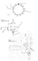
- Fig. 1 shows a rough schematic representation of a device 1 for forming containers.
- This device has a rotatable support, such as a blowing wheel 2, on which a plurality of blowing stations 4 is arranged.
- These blowing stations 4 serve in each case for forming plastic preforms 10 to plastic containers.
- the individual blow molding stations each have blow molds which form a cavity in their interior which serves to expand the plastic preforms 10.
- the individual blow molding stations also have stretch rods which stretch the plastic preforms in their longitudinal direction, so that the device is a stretch blow molding machine.
- Fig. 2a shows a valve block according to the prior art.
- This valve block in this case has a blowing nozzle 72 which is applied to the plastic preforms 10 in order to pressurize them for their expansion with compressed air.
- the reference numeral 110 refers to a housing of the valve block, which is designated in its entirety by 120.
- Reference numeral 118 denotes a muffler.
- Fig. 2b shows a more detailed illustration of a valve block according to the prior art. It can be seen that supply channels 104 are present here, via which the blown air can be supplied to the plastic preform 10.
- the reference numeral 106 refers to a movable piston which can be moved here along the double arrow P, for example by using guide curves or the like. Via an annular space 102, the blown air for the expansion of the plastic preforms 10 can be supplied by means of a valve (not shown).
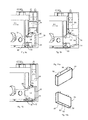
- Fig. 3 shows a representation of a device 20 according to the invention for the pneumatic control of the blowing pressure or of a control block 20 according to the invention.
- This control block has a control piston 14 which is displaceably mounted along the longitudinal axis L.
- this control piston 14 is mounted displaceably in a cylinder 12 or a guide body 12.
- the control piston 14 is at least partially formed of a metal and in particular it is formed on its outer periphery 14a of a metal.
- the cylinder or the guide cylinder 12 is formed here from a plastic. In this cylinder 12 also guide surfaces 42 and 44 are integrated, which are also made here of plastic.
- the reference numeral 28 denotes a sealing device, which is also arranged here in a circumferential groove 23 of the cylinder 12.
- the reference numeral 16 designates a main flow path, which when the valve is open (in Fig. 3 when the closed position is drawn) leads from an admission space 30 to an outlet 31. Along this main flow path 16, the blown air reaches the plastic preforms (not shown).
- the reference numeral 32 denotes openings which are distributed uniformly in the circumferential direction of the control piston 14 and in particular arranged in the cylinder 12 here.
- a surface 17 arranged on the outer circumference 14a of the control piston 14 lies opposite the individual openings 32 in a closed state of the valve.
- the reference numeral 46 refers to a sealing surface of the control piston 14, which the outlet channel 31 in the in Fig. 3 covering position shown.
- the sealing surface 46 also causes a seal of the main flow path 16.
- the control piston is in a closed state of the valve to a sealing body 36, which is formed here at the left end of the cylinder 12.
- this sealing body 36 is formed integrally with the cylinder 36. This is with reference to the FIGS. 8a-8d explained in more detail.
- this sealing surface 46 is disposed on the control piston 14, more specifically, a portion of the end face of the control piston forms the said sealing surface 46.
- the control piston 14, which is designed here as a metal piston (but can also be made of ceramic) is thus in an additional guide cylinder, ie the cylinder 12, which is made here of plastic out.
- the cylinder also serves to seal the end face of the control piston 14 against the metallic valve block. If the control piston 14 is made of ceramic, can be dispensed with the additional guide cylinder 12.
- the guide cylinder can in turn be accommodated in a receiving body such as a sleeve (not shown).
- the control piston 14 is mounted directly on the integrated into the cylinder 12 guide points or Passungs mismessern 42, 44.
- the guide piston has a cavity 52 in its interior, or is turned out hollow inside.
- the reference numeral 34 denotes a stopper screw. This stop screw 34 serves on the one hand to form a stop for the backward movement of the control piston 14 and on the other hand, this stop screw 34 also serves as a cover for reducing the control air / dead volume, since the stopper screw 34, the cavity 52 is covered.
- the air openings 32 are arranged uniformly on the circumference of the control piston 14, and thereby cause the piston is symmetrically flowed by the compressed air.
- the reference numeral 15 refers to a trained as an inclined surface Drfit Structure, which is arranged at the lower end of the control piston 14.
- This urging surface or oblique surface 15, which is formed circumferentially here, also serves as an urging surface.
- An urging surface is understood to mean a surface or a section which, by its (in particular geometrical) arrangement, is suitable for generating a force acting on a gaseous medium acting in the longitudinal direction of the control piston. Thus, the urging surface deflects a force acting on them preferred. As soon as the space 30 surrounding the control piston 14 is subjected to compressed air, this pressure also acts on this urging surface 15 and thus causes the control piston 14 to act in Fig. 3 pushed back to the right.
- the device 20 is designed so that in the presence of a control pressure in the control chamber 26 of, for example, 10 bar of the control piston 14 in the in Fig. 3 shown, left position. Only when the control pressure in the control chamber 26 is no longer present, the control piston 14 due to the blowing pressure in Fig. 3 move to the right. The control pressure acts on the control surface 24 of the control piston 14th
- Fig. 4 shows a further embodiment of a device according to the invention 20.
- a seal against the outlet 31 by means of a plastic disc 50 which has the same size areas A1, A2 on the printed pages. In this way, equal areas arise when sealing.
- the control piston 14 is mounted here on guide belts 62, 64, which are inserted in the cylinder 12. Again, a cavity 52 is provided to save weight and also in Fig. 3 illustrated stop screw. As in the case of Fig. 3 Here, too, a symmetrical flow of the control piston 12 is achieved by the uniform circumferentially arranged openings 32.
- the control piston can be made here of metal, ceramic, if necessary. Also as magnesium or hard rubber.
- the cylinder or the guide is advantageously made of metal or ceramic here.
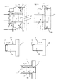
- Fig. 5a shows a further embodiment for illustrating the guide.
- a seal 29 is provided on the control piston 14, which serves to seal the 10 bar pressure chamber.
- Another seal 28 is disposed in the cylinder 12.
- the control piston 14 is guided here exclusively on the small diameter D1 of the cylinder 12.
- the reference numerals 42 and 44 relate again to the respective guide surfaces.
- Fig. 5b shows a further embodiment of a device according to the invention.
- a seal 29 is also provided in the control piston 12 and a seal 28 in the cylinder 12.
- the piston guide takes place here both on the small diameter D1, as well as on the large diameter D2 of the control piston 12.
- the reference numerals 42 and 45 refer to the respective guide surfaces.
- the guide surfaces are formed such that a purely metallic contact of the guide surfaces is avoided, so that, for example, the guide between a plastic surface and a metal surface or between two plastic surfaces takes place.
- FIGS. 6a to 6c show three possible embodiments of a control piston 14.
- the piston is in each case made of two components.
- the piston in this case has a base body 14b.
- a sealing surface 25 made of plastic is arranged on the main body 14b.
- a sealing surface 27 is provided, which is an area of the main body 14b engages behind. In this case, this sealing surface 27 is vulcanized onto the base body 14b.
- the sealing surface 25 is also made of plastic and vulcanized with a base portion 21 in the main body 14b.
- Fig. 7a shows a detailed view illustrating the sealing surfaces.
- the control piston has here a recess 18, so that the supplied blowing air flows to the control piston in full.
- the sealing takes place here via the two surfaces A1 and A2.
- a plastic disc 50 is also provided here, against which the control piston 14 rests over the surface A1 for the purpose of sealing.
- the two surfaces A1 and A2 are the same size here.
- Fig. 7b shows a further embodiment for illustrating the seal.
- the control piston 14 here again has a recess 19 which, however, here is designed as a circumferential groove.
- the reference numeral 46 refers in both representations to the formed on the control piston 14 sealing surface.
- the two surfaces A1 and A2 are parallel to each other and particularly preferably offset in the longitudinal direction of the control piston 14 to each other.
- FIGS. 8a-8d show various representations of the cylinder 12, partly with the control piston 14 arranged therein FIG. 8a it can be seen that on the cylinder 12, a sealing body 36 is formed. More precisely, this sealing body 36 is arranged integrally on the cylinder 12. In the Fig. 8a not shown) inner surface of the sealing body 36 serves to seal the valve when a corresponding end face of the control piston 14 bears against it.
- the sealing body 36 is arranged by means of webs 38 on the base body of the cylinder 12 and between these, the individual openings 32, via which the blowing air can enter, formed.
- Fig. 8b shows a representation of the in Fig. 8a
- the control piston 14 is formed here in two parts and more precisely has a stop screw 34 which is screwed into a corresponding cavity of the control piston.
- the reference numeral 48 refers to a circumferential projection which is arranged on the cylinder 12.
- the urging surface 15 can be seen, which causes when exposed to compressed air, that the control piston in Fig. 8b relative to the cylinder 12 moves to the left.
- Fig. 8c shows a sectional view of the cylinder 12 with disposed therein control piston 14. It can be seen that the circumferential projection 48 in a recess 49 which is formed in the control piston 14, can penetrate.
- the reference numeral 36a designates the above-mentioned inner surface of the sealing body 36 which together with the end face 14c of the control piston 14 (or a -particularly annular - part of this end face 14c serves to seal the valve.
- Fig. 8d shows a further sectional view, in which in particular the end face 14c of the control piston 14 is visible
- Fig. 9a shows a further possible embodiment of a device according to the invention.
- the control piston 14 is not in the 3 and 4 shown oblique surfaces 15. Therefore, originating from the annular space 30 Queranströmung on the control piston 14 causes no axial force, because the pressure is not present at the end face of the piston. For this reason, another (inevitable) control by means of two additional valves 82 and 84, which act here as pilot valves, is provided.
- a first pilot valve 82 it is possible to apply an annular surface 86 with control air, in order in this way the control piston 14 in Fig. 7 along the arrow P1 to move to its rear position (ie to the right). In this position, the working pressure air can flow into the plastic preform.
- control piston 14 can be achieved by a second pilot valve 84, which in turn acts on the control chamber 26 with compressed air and in this way a movement of the control piston 14 in Fig. 7 to the left, ie counter to the direction of arrow P1 causes.
- a combination of an additional piston and an air spring is used.
- This system pressure of 10 bar works here in the Control chamber 26 and causes in this way, that the control piston is pressed into the front position and thus closes the "P1" valve.
- the pilot valve 82 By means of the pilot valve 82, the annular surface 86 is supplied with control air and thereby the control piston 14 can be moved to the rear position and in this way, the working pressure air can flow into the plastic preform.
- the device has an additional piston.
- the working pressure air eg at 40 bar
- valve 84 By means of a pilot valve 84, the circular area or control surface 24 is supplied with control air and thereby the control piston 14 is moved to the front position and in this way closes the valve.
- the return of the valve it would also be possible for the return of the valve to be done in other ways, for example by a spring.
- an electromagnet could be provided which moves the control piston 14 in the figures to the right or opens the valve.
- the device or have the means for the pneumatic control of the blowing pressure on the pressure transducer.
- pressure transducer include the pressure transducer itself and the transmitter in a housing. So that the pressure sensor can be positioned closer to the process, it is proposed here to form the pressure sensor in two parts and, in particular, to provide the evaluation electronics at a distance from the actual pressure sensor.
- the transmitter and the pressure transducer themselves as different components and in particular carried out separately.
- the present invention is therefore further directed to a device according to the preamble of claim 1, wherein according to the invention this device comprises a pressure transducer for determining at least one pressure occurring in the device and wherein an evaluation of this pressure transducer is arranged separately from the actual pressure transducer.
- the pressure sensor is arranged directly on the unit for the pneumatic control of the blowing pressure.
- the pressure sensor can be positioned directly in the pressure chamber, for example, the annular chamber 30 acted upon by the blowing pressure, and the transmitter outside. In this way, the control block can be made more compact overall.
- valves such as the pilot valves 82 and 84 by air channels (not shown) in the control block.
- air channels not shown
- these valves are provided in particular redundantly and in particular or intended only for safe opening of the device in case of failure of a pilot valve. It would be possible to install two (redundant) pilot valves on an outlet valve, which is advantageous for a space-saving solution for a safe opening.
- Fig. 11a and 11b show two possible embodiments of an aseptic pilot valve 90.
- the reference numerals 92 and 94 each refer to a signal terminal in Fig. 10b, the two openings 96 and 98 on working connections, the reference numeral 95 to a connection for a silencer and the reference numeral 93 to a Feed port (especially for air).
- the signal connection 92 and 94 can be designed, for example, as a 1P67 suitable plug or as a gap-free potted cable.
- the air connections (for air supply and silencer) can be separated for each pilot valve as well as shared.
Abstract
Description
Die vorliegende Erfindung bezieht sich auf eine Vorrichtung zur Blasformung von Behältnissen. Derartige Vorrichtungen sind aus dem Stand der Technik seit langem bekannt. Dabei werden üblicherweise erwärmte Kunststoffvorformlinge mit Druckluft beaufschlagt um auf diese Weise zu Kunststoffbehältnissen umgeformt zu werden. Üblicherweise weisen derartigen Vorrichtungen zum Umformen der Kunststoffvorformlinge zu Kunststoffbehältnissen ein Blasrad auf, an dem eine Vielzahl von Blasstationen angeordnet ist. Diese Blasstationen wiederum bilden hierbei Hohlräume aus, innerhalb derer die Kunststoffvorformlinge expandiert werden.The present invention relates to a device for blow molding containers. Such devices have been known for a long time from the prior art. In this case, heated plastic preforms are usually subjected to compressed air in order to be converted in this way to plastic containers. Usually, such devices for forming the plastic preforms to plastic containers on a blowing wheel on which a plurality of blow molding stations is arranged. These blow stations in turn form cavities within which the plastic preforms are expanded.
Die Beaufschlagung der Kunststoffvorformlinge mit Druckluft erfolgt dabei üblicherweise mittels Blasdüsen. Der zur Expansion der Kunststoffvorformlinge nötige Blasdruck wird dabei üblicherweise mittels Ventilblöcken zur Verfügung gestellt. Aus dem Stand der Technik sind diverse Ausgestaltungen dieser Ventilblöcke bzw. Ventilmechanismen bekannt.The loading of the plastic preforms with compressed air is usually carried out by means of blowing nozzles. The necessary for the expansion of the plastic preforms blow pressure is usually provided by means of valve blocks available. Various configurations of these valve blocks or valve mechanisms are known from the prior art.
Die
Aus der
Diese Vorrichtung arbeitet zwar zufriedenstellend, es hat sich jedoch gezeigt, dass die auf diese Weise hergestellten Steuerkolben teilweise einem erhöhten Verschleiß unterliegen.Although this device works satisfactorily, it has been found that the control pistons produced in this way are partially subject to increased wear.
Der vorliegenden Erfindung liegt daher Aufgabe zugrunde, eine Vorrichtung zur Blasformung von Behältern zur Verfügung zu stellen, welche eine erhöhte Lebensdauer aufweist. Dies wird erfindungsgemäß durch den Gegenstand des unabhängigen Anspruchs erreicht. Vorteilhafte Ausführungsformen und Ausbildungen sind Gegenstand der Unteransprüche.The present invention is therefore based on the object of providing a device for blow-molding containers which has an increased service life. This is achieved according to the invention by the subject matter of the independent claim. Advantageous embodiments and embodiments are the subject of the dependent claims.
Bei einer ersten Ausgestaltung weist die erfindungsgemäße Vorrichtung auf einem Blasrad angeordnete Blasstationen zur Blasformung von Behältern aus einem thermoplastischen Material auf. Weiterhin weist die Vorrichtung eine Einrichtung zur pneumatischen Steuerung eines Blasdrucks auf, wobei die Einrichtung zur pneumatischen Steuerung einen in einem Zylinder geführten Steuerkolben aufweist, der in Richtung einer Kolbenlängsachse verschieblich gelagert ist und bei der durch den Zylinder - im Folgenden auch als Führungszylinder oder allgemein Führungskörper bezeichnet - hindurch ein vom Steuerkolben verschließbarer Hauptströmungsweg verläuft. Weiterhin ist der Steuerkolben mit einer Steuerfläche versehen, die einem Steuerraum des Zylinders zugewandt ist und die zur Übertragung einer Steuerkraft auf den Steuerkolben ausgebildet ist.In a first embodiment, the device according to the invention has blowing stations arranged on a blowing wheel for blow molding containers made of a thermoplastic material. Furthermore, the device has a device for the pneumatic control of a blowing pressure, wherein the means for pneumatic control comprises a guided in a cylinder control piston which is displaceably mounted in the direction of a piston longitudinal axis and in which by the cylinder - hereinafter also as a guide cylinder or generally guide body designated - passes through a closable by the control piston main flow path. Furthermore, the control piston is provided with a control surface, which faces a control chamber of the cylinder and which is designed to transmit a control force to the control piston.
Erfindungsgemäß blockiert in wenigstens einer Position des Steuerkolbens eine Umfangswandung des Steuerkolbens den Hauptströmungsweg. Mit anderen Worten ist insbesondere der Hauptströmungsweg in einem geschlossenen Zustand der Einrichtung von einer Umfangswandung des Steuerkolbens blockiert.According to the invention blocked in at least one position of the control piston, a peripheral wall of the control piston the main flow path. In other words, in particular, the main flow path in a closed state of the device is blocked by a circumferential wall of the control piston.
Während im Stand der Technik üblicherweise nur die Stirnflächen des Steuerkolbens den Hauptströmungsweg für die Blasluft blockieren, wird hier vorgeschlagen, dass zusätzlich zumindest auch die Umfangswandung den Hauptströmungsweg blockiert. Bei den Behältern handelt es sich insbesondere um Kunststoffvorformlinge bzw. die daraus zu formenden Kunststoffbehälter. Unter einem Blockieren wird dabei verstanden, dass die besagte Umfangswandung dem Hauptströmungspfad im Weg steht. Dabei muss die Umfangswandung den Hauptströmungspfad nicht notwendigerweise abdichten. Vielmehr ist es möglich, dass die Abdichtung über eine Stirnfläche des Steuerkolbens bzw. einen Teil dieser Stirnfläche erfolgt.While in the prior art usually only the end faces of the control piston block the main flow path for the blowing air, it is proposed here that additionally at least the circumferential wall blocks the main flow path. The containers are, in particular, plastic preforms or the plastic containers to be molded therefrom. A blocking is understood to mean that said peripheral wall is in the way of the main flow path. The peripheral wall does not necessarily have to seal the main flow path. Rather, it is possible that the sealing takes place via an end face of the control piston or a part of this end face.
Vorteilhaft ist dabei ein Einlass für die Druckluft in einer Umfangswandung des Zylinders angeordnet. Vorteilhaft ist ein Einlass für die Blasluft bzw. Druckluft gegenüber dem Auslass in der Längsrichtung des Steuerkolbens versetzt, d.h. höhenversetzt. Im Stand der Technik wird üblicherweise durch eine Stirnfläche des Steuerkolbens sowohl der Einlass für die Druckluft als auch der Auslass für die Druckluft abgedeckt bzw. blockiert. Im Rahmen der hier vorliegenden Erfindung wird vorgeschlagen, dass zumindest entweder der Einlass für die Blasluft oder der Auslass für die Blasluft, bevorzugt der Einlass für die Blasluft von einer Umfangswandung des Steuerkolbens in einem geschlossenen Zustand der Einrichtung bzw. des Ventils blockiert bzw. (zumindest teilweise) versperrt wird. Der Vorteil dieser Ausführungsform besteht darin, dass so eine gleichmäßigere Anströmung des Steuerkolbens in dessen Umfangsrichtung möglich ist.An inlet for the compressed air is advantageously arranged in a circumferential wall of the cylinder. Advantageously, an inlet for the blast air or compressed air is offset relative to the outlet in the longitudinal direction of the control piston, i. offset in height. In the prior art, both the inlet for the compressed air and the outlet for the compressed air is usually covered or blocked by an end face of the control piston. In the context of the present invention, it is proposed that at least either the inlet for the blown air or the outlet for the blown air, preferably the inlet for the blown air from a peripheral wall of the control piston in a closed state of the device or the valve blocked or (at least partially) is blocked. The advantage of this embodiment is that a more uniform flow of the control piston in the circumferential direction is possible.
Eine weitere Ausgestaltung einer erfindungsgemäßen Vorrichtung weist auf einem Blasrad angeordnete Blasstationen zur Blasformung von Behältern aus einem thermoplastischen Material auf. Weiterhin weist die Vorrichtung eine Einrichtung zur pneumatischen Steuerung eines Blasdrucks auf, wobei die Einrichtung zur pneumatischen Steuerung einen in einem Zylinder geführten Steuerkolben aufweist, der in Richtung einer Kolbenlängsachse verschieblich gelagert ist und bei der durch den Zylinder hindurch ein vom Steuerkolben verschließbarer Hauptströmungsweg verläuft. Weiterhin ist der Steuerkolben mit einer Steuerfläche versehen, die einem Steuerraum des Zylinders zugewandt ist und die zur Übertragung einer Steuerkraft auf den Steuerkolben ausgebildet ist.A further embodiment of a device according to the invention has blowing stations arranged on a blowing wheel for blow molding containers made of a thermoplastic material. Furthermore, the device has a device for the pneumatic control of a blowing pressure, wherein the means for pneumatic control comprises a guided in a cylinder control piston which is displaceably mounted in the direction of a piston longitudinal axis and in which passes through the cylinder a closable by the control piston main flow path. Furthermore, the control piston is provided with a control surface, which faces a control chamber of the cylinder and which is designed to transmit a control force to the control piston.
Erfindungsgemäß ist dabei der Steuerkolben mindestens bereichsweise aus einem Metall oder einer Keramik ausgebildet.According to the invention, the control piston is at least partially formed of a metal or a ceramic.
Es wird daher vorgeschlagen, ein pneumatisch gesteuertes Ventil zur Verfügung zu stellen, dessen Steuerkolben bereichsweise aus einem Metall oder einer Keramik ausgebildet ist. Durch diese Ausbildung des Steuerkolbens aus Metall oder Keramik kann die Widerstandsfähigkeit des Steuerkolbens und damit eines beweglichen Ventilelements erhöht werden und auf diese Weise auch die Lebensdauer der Einrichtung d.h. des Ventils in seiner Gesamtheit.It is therefore proposed to provide a pneumatically controlled valve available, the control piston is partially formed of a metal or a ceramic. By this design of the control piston of metal or ceramic, the resistance of the control piston and thus a movable valve element can be increased and in this way the life of the device, i. of the valve in its entirety.
Bevorzugt ist der Hauptströmungsweg derart angeordnet, dass bei einer Absenkung des Steuerdrucks der Steuerkolben durch den einwirkenden Hochdruck in Richtung der Kolbenlängsachse verschoben wird. Es wäre jedoch auch möglich, dass die Verschiebung des Steuerkolbens nicht unter Einfluss des Hochdrucks bzw. Blasdrucks erfolgt sondern in anderer Weise, etwa durch ein zusätzliches Pilotventil, eine Feder, magnetische Kräfte oder dergleichen.Preferably, the main flow path is arranged such that is displaced in a lowering of the control pressure of the control piston by the acting high pressure in the direction of the piston longitudinal axis. However, it would also be possible that the displacement of the control piston does not take place under the influence of the high pressure or blowing pressure but in another way, for example by an additional pilot valve, a spring, magnetic forces or the like.
Vorteilhaft weisen die einzelnen Blasstationen jeweils Blasformen auf, innerhalb derer Kunststoffvorformlinge zu den Kunststoffbehältnissen expandierbar sind.Advantageously, the individual blowing stations each have blow molds within which plastic preforms are expandable to the plastic containers.
Bei einer weiteren vorteilhaften Ausführungsform weist der Zylinder zumindest teilweise aus einem Kunststoff gefertigte Führungsflächen zum Führen des Steuerkolbens auf. Auf diese Weise kann ein metallischer Kontakt mit dem Steuerkolben vermieden werden.In a further advantageous embodiment, the cylinder at least partially made of a plastic guide surfaces for guiding the control piston. In this way, a metallic contact with the control piston can be avoided.
Bei einer weiteren vorteilhaften Ausführungsform ist der Hauptströmungsweg in dem Zylinder angeordnet. Während im Falle der
Nach einer weiteren vorteilhaften Ausführungsform weist die Einrichtung zur pneumatischen Steuerung eine Dichtfläche zum Verschließen des Hauptströmungswegs auf und diese Dichtfläche ist an einem Außenumfang des Zylinders angeordnet. Die Stirnfläche des Kolbens wird dabei nicht als Aussenumfang verstanden Damit wird vorgeschlagen, dass der Steuerkolben als zumindest teilweise metallischer oder keramischer Kolben und bevorzugt als Metallkolben oder Keramikkolben ausgeführt ist, der bevorzugt in einer Kunststoffbuchse geführt ist wobei vorteilhaft in diese Kunststoffbuchse auch die besagten Dichtflächen integriert sind. Vorzugsweise sind dabei die Dichtfläche und die besagte Führung für den Steuerkolben zweiteilig ausgebildet.According to a further advantageous embodiment, the device for pneumatic control has a sealing surface for closing the main flow path and this sealing surface is arranged on an outer circumference of the cylinder. The end face of the piston is not understood to be an outer circumference. It is proposed that the control piston is designed as an at least partially metallic or ceramic piston and preferably as a metal piston or ceramic piston, which is preferably guided in a plastic bushing and advantageously also integrates the said sealing surfaces into this plastic bushing are. Preferably, the sealing surface and the said guide for the control piston are formed in two parts.
Bei einer weiteren vorteilhaften Ausführungsform ist der Steuerkolben vollständig aus einem Metall ausgebildet. Vorteilhaft ist der Steuerkolben aus Aluminium ausgebildet.In a further advantageous embodiment, the control piston is completely formed from a metal. Advantageously, the control piston is formed of aluminum.
Bei einer weiteren bevorzugten Ausführungsform weist der Steuerkolben einen Hohlraum auf. Dieser Hohlraum kann dabei im Inneren des Steuerkolbens ausgeführt sein. Mit anderen Worten kann hier zur Gewichtserleichterung der Kolben innen hohl ausgeführt beispielsweise ausgedreht sein.In a further preferred embodiment, the control piston has a cavity. This cavity may be embodied in the interior of the control piston. In other words, here for weight reduction of the piston inside running hollow, for example, be turned out.
Bei einer weiteren vorteilhaften Ausführungsform ist in dem Zylinder wenigstens eine Dichtungseinrichtung zum Abdichten der Bewegung des Steuerkolbens (entlang dessen Längsrichtung) angeordnet. Genauer gesagt handelt sich hierbei um Dichtflächen, die zum Abdichten der Bewegung des Steuerkolbens ausgebildet sind.In a further advantageous embodiment, at least one sealing device for sealing the movement of the control piston (along its longitudinal direction) is arranged in the cylinder. More specifically, these are sealing surfaces that are designed to seal the movement of the control piston.
Bei einer weiteren vorteilhaften Ausführungsform weist die Vorrichtung einen den Steuerkolben in dessen Umfangsrichtung (bzw. um dessen Bewegungsrichtung herum) umgebenden Beaufschlagungsraum auf, der insbesondere mit Blasluft beaufschlagbar ist. Dies bedeutet, dass im Gegensatz zum Stand der Technik der Steuerkolben nicht ausschließlich in seiner Längsrichtung mit dem Druck beaufschlagt wird sondern voll umfänglich von der Seite her. Auf diese Weise ist eine symmetrische Anströmung des Steuerkolbens möglich. Vorteilhaft weist die Vorrichtung wenigstens zwei, bevorzugt wenigstens drei und bevorzugt eine Vielzahl von gleichmäßig am Umfang des Steuerkolbens angeordneten Luftöffnungen auf. In einem geschlossenen Zustand der Einrichtung bzw. des Ventils werden diese Luftöffnungen vorteilhaft durch den Aussenumfang des Steuerkolbens verschlossen.In a further advantageous embodiment, the device has a control chamber in the circumferential direction (or around its direction of movement) surrounding Beaufschlagungsraum on which in particular can be acted upon with blown air. This means that in contrast to the prior art, the control piston is not acted upon exclusively in its longitudinal direction with the pressure but fully circumferentially from the side. In this way, a symmetrical flow of the control piston is possible. Advantageously, the device has at least two, preferably at least three and preferably a plurality of uniformly arranged on the circumference of the control piston air openings. In a closed state of the device or of the valve, these air openings are advantageously closed by the outer circumference of the control piston.
Bei einer weiteren vorteilhaften Ausführungsform weist der Steuerkolben eine Drängfläche auf, welche den Steuerkolben bei Beaufschlagung mit Druckluft - insbesondere in der radialen Richtung des Steuerkolbens d.h. einer zu der Längsrichtung des Steuerkolbens senkrecht stehenden Richtung - entlang der Kolbenlängsachse verschiebt. Bei dem Stand der Technik kann der Steuerkolben unmittelbar durch die in Längsrichtung auftreffende Luft verschoben werden. Da, wie oben erwähnt, bei der hier dargestellten Ausführungsform die Luft nicht mit einer Längsrichtung auf den Steuerkolben trifft sondern seitwärts, ist vorteilhaft die genannte Drängfläche vorgesehen. Dabei kann es sich beispielsweise um eine am Kolbenende angeordnete Schrägflache handeln, die bei der Beaufschlagung mit Druckluft in einer radialen bzw. senkrecht zu der Bewegungsrichtung des Steuerkolbens stehenden Richtung eine Bewegung des Steuerkolbens in seiner Gesamtheit bewirkt. Daneben kann die besagte Drängfläche an einem Außenumfang des Steuerkolbens angeordnet sein. Dies wird unter Bezugnahme auf die Figuren genauer erläutert.In a further advantageous embodiment, the control piston on an urging surface, which shifts the control piston upon application of compressed air - in particular in the radial direction of the control piston that is a direction perpendicular to the longitudinal direction of the control piston direction along the piston longitudinal axis. In the prior art, the control piston can be displaced directly by the longitudinally impinging air. Since, as mentioned above, in the embodiment shown here, the air does not meet with a longitudinal direction on the control piston but sideways, is advantageous to said urging surface provided. This may be, for example, an inclined surface arranged at the piston end, which causes a movement of the control piston in its entirety when pressurized air is applied in a direction that is radial or perpendicular to the direction of movement of the control piston. In addition, said urging surface may be arranged on an outer circumference of the control piston. This will be explained in more detail with reference to the figures.
Bei einer weiteren bevorzugten Ausführungsform ist der Steuerkolben mehrteilig und insbesondere zweiteilig ausgebildet. Dabei kann eines dieser mehreren bzw. beiden Teile des Steuerkolbens beispielsweise aus einem Metall und das andere aus Kunststoff gefertigt sein.In a further preferred embodiment, the control piston is designed in several parts and in particular in two parts. In this case, one of these several or both parts of the control piston may for example be made of a metal and the other of plastic.
Bei einer weiteren vorteilhaften Ausführungsform ist an dem Steuerkolben ein Anschlagmittel, wie beispielsweise eine Anschlagsschraube, angeordnet. Diese Anschlagsschraube dient dabei zum einen als Anschlag und zum anderen vorteilhaft auch als Deckel zur Reduzierung des Steuerlufttotraumvolumens.In a further advantageous embodiment, a stop means, such as a stop screw, is arranged on the control piston. This stop screw serves on the one hand as a stop and on the other advantageous as a lid for reducing the Steuerlufttotraumvolumens.
Bei einer bevorzugten Ausführungsform ist der Steuerkolben aus einem Material hergestellt, welches aus einer Gruppe ausgewählt ist, welche Metalle, Keramik, Magnesium, Hartgummi und der gleichen enthält. Die Führung bzw. der Führungszylinder ist, wie oben erwähnt, vorteilhaft aus einem Kunststoff hergestellt.In a preferred embodiment, the control piston is made of a material selected from a group including metals, ceramics, magnesium, hard rubber and the like. The guide or the guide cylinder is, as mentioned above, advantageously made of a plastic.
Es wäre jedoch auch möglich, dass der Führungszylinder aus Metall oder Keramik ausgebildet ist. Auch wäre es möglich, dass der Führungszylinder mehrteilig aufgebaut ist und beispielsweise einen aus Kunststoff gefertigten Führungskörper zum Führen des Steuerkolbens aufweist sowie einen Grundkörper, der diesen Führungskörper trägt. Dieser Grundkörper kann dabei auch den Steuerraum ausbilden.However, it would also be possible for the guide cylinder to be made of metal or ceramic. It would also be possible that the guide cylinder is constructed in several parts and, for example, has a guide body made of plastic for guiding the control piston and a base body which carries this guide body. This body can also form the control room.
Bei einer weiteren vorteilhaften Ausführungsform weist der Steuerkolben ein Kunststoffelement auf. Auf diese Weise ist es möglich, dass sich der Steuerkolben aus einem metallischen Anteil und einem Kunststoffanteil zusammensetzt. So wäre es beispielsweise möglich, dass in einem Hohlraum des Steuerkolbens ein Kunststoffsegment untergebracht ist. Auch wäre möglich, dass eine Dichtfläche am Ende des Steuerkolbens aus Kunststoff ausgebildet ist. Daneben wäre es möglich, dass ein Kunststoffelement in einen ansonsten aus Metall bestehenden Steuerkolben eingearbeitet ist.In a further advantageous embodiment, the control piston on a plastic element. In this way, it is possible that the control piston composed of a metallic portion and a plastic portion. For example, it would be possible for a plastic segment to be accommodated in a cavity of the control piston. It would also be possible that a sealing surface is formed at the end of the control piston made of plastic. In addition, it would be possible that a plastic element is incorporated in an otherwise made of metal control piston.
Weitere Vorteile und Ausführungsformen ergeben sich aus den beigefügten Zeichnungen:Further advantages and embodiments will be apparent from the attached drawings:
Darin zeigen:
- Fig. 1
- eine schematische Darstellung einer Vorrichtung zum Blasformen von Behältern;
- Fig. 2a
- einen Ventilblock nach dem Stand der Technik;
- Fig. 2b
- eine Detaildarstellung des Ventilblocks aus
Figur 2a ; - Fig. 3
- eine Darstellung einer erfindungsgemäßen Einrichtung zur pneumatischen Steuerung des Blasdrucks;
- Fig. 4
- eine weitere Ausführungsform einer erfindungsgemäßen Einrichtung;
- Fig. 5a
- eine Detaildarstellung einer erfindungsgemäßen Einrichtung;
- Fig. 5b
- eine weitere Detaildarstellung einer erfindungsgemäßen Einrichtung;
- Fig. 6a - 6c
- drei mögliche Varianten für Steuerkolben;
- Fig. 7a - 7b
- zwei Teilansichten einer erfindungsgemäßen Vorrichtung;
- Fig. 8a - 8d
- vier Darstellungen einer vorteilhaften Ausführungsform eines Ventils
- Fig.9a
- eine weitere Ausführungsform einer erfindungsgemäßen Einrichtungsform zur pneumatischen Steuerung;
- Fig. 9b
- eine weitere Ausführungsform einer erfindungsgemäßen Einrichtung zur Steuerung des Blasdrucks;
- Fig. 10
- eine weitere erfindungsgemäße Ausführungsform einer Einrichtung zur Steuerung des Blasdrucks;
- Fig. 11 a, 11 b
- zwei Darstellungen eines aseptischen Pilotventils.
- Fig. 1
- a schematic representation of an apparatus for blow molding containers;
- Fig. 2a
- a valve block according to the prior art;
- Fig. 2b
- a detailed representation of the valve block
FIG. 2a ; - Fig. 3
- an illustration of a device according to the invention for the pneumatic control of the blowing pressure;
- Fig. 4
- a further embodiment of a device according to the invention;
- Fig. 5a
- a detailed representation of a device according to the invention;
- Fig. 5b
- a further detail of a device according to the invention;
- Fig. 6a - 6c
- three possible variants for control pistons;
- Fig. 7a - 7b
- two partial views of a device according to the invention;
- Fig. 8a - 8d
- four representations of an advantageous embodiment of a valve
- 9a
- a further embodiment of an inventive device form for pneumatic control;
- Fig. 9b
- a further embodiment of a device according to the invention for controlling the blowing pressure;
- Fig. 10
- a further embodiment of a device according to the invention for controlling the blowing pressure;
- Fig. 11 a, 11 b
- two illustrations of an aseptic pilot valve.
Der Steuerkolben 14 ist dabei wenigstens abschnittsweise aus einem Metall ausgebildet und insbesondere ist er an seinem Außenumfang 14a aus einem Metall ausgebildet. Der Zylinder bzw. der Führungszylinder 12 ist hier aus einem Kunststoff ausgebildet. In diesen Zylinder 12 sind auch Führungsflächen 42 und 44 integriert, die hier ebenfalls aus Kunststoff gefertigt sind. Das Bezugszeichen 28 kennzeichnet eine Dichtungseinrichtung, die hier ebenfalls in einer umlaufenden Nut 23 des Zylinders 12 angeordnet ist. Das Bezugszeichen 16 kennzeichnet einen Hauptströmungsweg, der bei geöffnetem Ventil (in
Das Bezugszeichen 32 kennzeichnet Öffnungen, welche hier gleichmäßig in Umfangsrichtung des Steuerkolbens 14 verteilt und insbesondere in dem Zylinder 12 angeordnet sind. Eine am Aussenumfang 14a des Steuerkolbens 14 angeordnete Fläche 17 liegt den einzelnen Öffnungen 32 in einem geschlossenen Zustand des Ventils gegenüber..The
Das Bezugszeichen 46 bezieht sich auf eine Dichtfläche des Steuerkolbens 14, welche den Austrittskanal 31 in der in
Bei der in
Der Steuerkolben 14 ist direkt auf den in den Zylinder 12 integrierten Führungsstellen bzw. Passungsdurchmessern 42, 44 gelagert. Zur Gewichtseinsparung weist der Führungskolben in seinem Inneren einen Hohlraum 52 auf, bzw. ist innen hohl ausgedreht. Das Bezugszeichen 34 kennzeichnet eine Anschlagschraube. Diese Anschlagschraube 34 dient einerseits dazu, um einen Anschlag für die Rückwärtsbewegung des Steuerkolbens 14 auszubilden und andererseits dient diese Anschlagschraube 34 auch als Deckel zur Reduzierung des Steuerluft-/ Totvolumens, da durch diese Anschlagschraube 34 der Hohlraum 52 abgedeckt wird. Die Luftöffnungen 32 sind gleichmäßig am Umfang des Steuerkolbens 14 angeordnet, und bewirken dadurch, dass der Kolben symmetrisch von der Druckluft angeströmt wird.The
Das Bezugszeichen 15 bezieht sich auf eine als Schrägfläche ausgebildete Drängfläche, die am unteren Ende des Steuerkolbens 14 angeordnet ist. Diese Drängfläche bzw. Schrägfläche 15, die hier umlaufend ausgebildet ist, dient dabei auch als Drängfläche. Unter einer Drängfläche wird eine Fläche bzw. ein Abschnitt verstanden, der durch seine (insbesondere geometrische) Anordnung geeignet ist, bei Beaufschlagung mit einem gasförmigen Medium eine Kraft zu erzeugen, die hier in der Längsrichtung des Steuerkolbens wirkt. Damit lenkt die Drängfläche eine auf sie wirkende Kraft bevorzugt um. Sobald der den Steuerkolben 14 umgebende Raum 30 mit Druckluft beaufschlagt wird, wirkt dieser Druck auch auf diese Drängfläche 15 und bewirkt damit, dass der Steuerkolben 14 in
Dabei ist jedoch die Einrichtung 20 so ausgelegt, dass bei Vorhandensein eines Steuerdrucks in dem Steuerraum 26 von beispielsweise 10 bar der Steuerkolben 14 in der in
Der Steuerkolben 14 ist hier auf Führungsbändern 62, 64 gelagert, welche in dem Zylinder 12 eingelegt sind. Auch hier ist wieder ein Hohlraum 52 zur Gewichtseinsparung vorgesehen sowie die auch in
Der Steuerkolben kann hier aus Metall, Keramik, ggfs. auch als Magnesium oder Hartgummi hergestellt sein. Der Zylinder bzw. die Führung ist hier vorteilhaft aus Metall oder Keramik hergestellt.The control piston can be made here of metal, ceramic, if necessary. Also as magnesium or hard rubber. The cylinder or the guide is advantageously made of metal or ceramic here.
Vorzugsweise sind bei allen Ausführungsformen die Führungsflächen derart ausgebildet, dass ein rein metallischer Kontakt der Führungsflächen vermieden wird, so dass beispielsweise die Führung zwischen einer Kunststofffläche und einer Metallfläche oder zwischen zwei Kunststoffflächen erfolgt.Preferably, in all embodiments, the guide surfaces are formed such that a purely metallic contact of the guide surfaces is avoided, so that, for example, the guide between a plastic surface and a metal surface or between two plastic surfaces takes place.
Die
Bei der in
Die
Bei der in
Bei der in
Mittels eines Pilotventils 84 wird die Kreisfläche bzw. Steuerfläche 24 mit Steuerluft beaufschlagt und dadurch wird der Steuerkolben 14 in die vordere Stellung bewegt und auf diese Weise schließt das Ventil. Es wäre jedoch auch möglich, dass die Rückstellung des Ventils in anderer Weise, etwa durch eine Feder erfolgt. Auch könnte ein Elektromagnet vorgesehen sein, der den Steuerkolben 14 in den Figuren nach rechts bewegt bzw. das Ventil öffnet.By means of a
Bei einer vorteilhaften Ausführungsform weist die Vorrichtung bzw. weisen die Einrichtungen zur pneumatischen Steuerung des Blasdrucks Druckaufnehmer auf. Üblicherweise beinhalten derartige Druckaufnehmer den Druckaufnehmer selbst und die Auswerteelektronik in einem Gehäuse. Damit der Druckaufnehmer näher am Prozess positioniert werden kann, wird hier vorgeschlagen, den Druckaufnehmer zweiteilig auszubilden und insbesondere die Auswerteelektronik beabstandet von dem eigentlichen Druckaufnehmer vorzusehen. Vorteilhaft werden daher die Auswerteelektronik und der Druckaufnehmer selbst als unterschiedliche Bauteile und insbesondere getrennt voneinander ausgeführt.In an advantageous embodiment, the device or have the means for the pneumatic control of the blowing pressure on the pressure transducer. Typically, such pressure transducer include the pressure transducer itself and the transmitter in a housing. So that the pressure sensor can be positioned closer to the process, it is proposed here to form the pressure sensor in two parts and, in particular, to provide the evaluation electronics at a distance from the actual pressure sensor. Advantageously, therefore, the transmitter and the pressure transducer themselves as different components and in particular carried out separately.
Die vorliegende Erfindung ist daher weiterhin auf eine Vorrichtung nach dem Oberbegriff von Anspruch 1 gerichtet, wobei erfindungsgemäß diese Vorrichtung einen Druckaufnehmer zum Bestimmen wenigstens eines in der Einrichtung auftretenden Drucks aufweist und wobei eine Auswerteelektronik dieses Druckaufnehmers getrennt von dem eigentlichen Druckaufnehmer angeordnet ist. Bevorzugt ist der Druckaufnehmer unmittelbar an der Einheit zur pneumatischen Steuerung des Blasdrucks angeordnet.The present invention is therefore further directed to a device according to the preamble of
Mit anderen Worten kann der Druckaufnehmer direkt in der Druckkammer, beispielsweise der durch den Blasdruck beaufschlagten Ringkammer 30 positioniert werden und die Auswerteelektronik außerhalb. Auf diese Weise kann der Steuerblock insgesamt kompakter gebaut werden.In other words, the pressure sensor can be positioned directly in the pressure chamber, for example, the
Bei einer weiteren vorteilhaften Ausführungsform, welche jedoch auch unabhängig von der Eingangs beschriebenen Erfindung Anwendung finden kann, erfolgt die Entlüftung der Ventile, wie beispielsweise der Pilotventile 82 und 84 durch (nicht gezeigte) Luftkanäle im Steuerblock. Auf diese Weise ist es möglich, den in
Bei einer weiteren vorteilhaften Ausführungsform weist die Einrichtung zur pneumatischen Steuerung zwei Pilotventile auf und weiterhin weist der Steuerblock zwei Auslauss-(exhaust) Ventile auf. Diese Ventile sind dabei jedoch insbesondere redundant vorgesehen und insbesondere bzw. nur zum sicheren Öffnen der Einrichtung bei Ausfall eines Pilotventils gedacht. Dabei wäre es möglich, zwei (redundante) Pilotventile an einem Auslassventil zu verbauen, was vorteilhaft für eine platzsparende Lösung für ein sicheres Öffnen ist.In a further advantageous embodiment, the device for pneumatic control on two pilot valves and further, the control block on two exhaust valves (exhaust) on. However, these valves are provided in particular redundantly and in particular or intended only for safe opening of the device in case of failure of a pilot valve. It would be possible to install two (redundant) pilot valves on an outlet valve, which is advantageous for a space-saving solution for a safe opening.
Die Anmelderin behält sich vor sämtliche in den Anmeldungsunterlagen offenbarte Merkmale als erfindungswesentlich zu beanspruchen, sofern sie einzeln oder in Kombination gegenüber dem Stand der Technik neu sind.The Applicant reserves the right to claim all features disclosed in the application documents as essential to the invention, provided that they are novel individually or in combination with respect to the prior art.
- 11
- Vorrichtungcontraption
- 22
- Blasradblow wheel
- 44
- Blasstationenblowing stations
- 1010
- KunststoffvorformlingeThe plastic preforms
- 1212
- (Führungs-)Zylinder, Führungskörper(Guide) cylinder, guide body
- 1414
- Steuerkolbenspool
- 14a14a
- Aussenumfang des SteuerkolbensOuter circumference of the control piston
- 14b14b
- Grundkörperbody
- 14c14c
- Stirnfläche des SteuerkolbensFace of the control piston
- 1515
- DrängflächeDrängfläche
- 1616
- Hauptströmungswegmain flow
- 1717
- Fläche des SteuerkolbensSurface of the control piston
- 1818
- Ausnehmungrecess
- 1919
- nutförmige Ausnehmunggroove-shaped recess
- 2020
- Steuerblock, EinrichtungControl block, device
- 2121
- Grundabschnittbase portion
- 2323
- Nutgroove
- 2424
- Steuerflächecontrol surface
- 2525
- Dichtflächesealing surface
- 2626
- Steuerraumcontrol room
- 2727
- Dichtflächesealing surface
- 2828
- Dichtungseinrichtungseal means
- 2929
- Dichtungpoetry
- 3030
- Beaufschlagungsraum, RingraumBeaufschlagungsraum, annulus
- 3131
- Auslass, AustrittskanalOutlet, outlet channel
- 3232
- Öffnungenopenings
- 3434
- Anschlagschraubestop screw
- 3636
- Dichtkörpersealing body
- 36a36a
- Innenfläche des DichtkörpersInner surface of the sealing body
- 3838
- StegeStege
- 42, 44, 4542, 44, 45
- Führungsflächen, PassungsdurchmesserGuide surfaces, fitting diameter
- 4646
- Dichtflächesealing surface
- 4848
- (ringförmiger) Vorsprung(annular) projection
- 4949
- Ausnehmungrecess
- 5252
- Hohlraumcavity
- 6262
- erstes Pilotenventilfirst pilot valve
- 62, 6462, 64
- Führungsbänderguide belts
- 7272
- Blasdüseblow nozzle
- 82, 8482, 84
- (Pilot)-Ventile(Pilot) valves
- 8686
- Ringflächering surface
- 9090
- aseptisches Pilotventilaseptic pilot valve
- 92, 9492, 94
- Signalanschlusssignal connection
- 9393
- Zuführanschlusssupply port
- 9595
- Anschluss für SchalldämpferConnection for silencer
- 96,9896.98
- Arbeitsanschlüsseworking lines
- 102102
- Ringraum (Stand der Technik)Annular space (prior art)
- 104104
- Zuführkanäle (Stand der Technik)Feed channels (prior art)
- 106106
- beweglicher Kolben (Stand der Technik)movable piston (prior art)
- 110110
- Gehäusecasing
- 118118
- Schalldämpfersilencer
- 120120
- Ventilblock (Stand der Technik)Valve block (prior art)
- A1, A2A1, A2
- große Flächenlarge areas
- D1D1
- kleiner Durchmessersmall diameter
- D2D2
- großer Durchmesserbig diameter
- LL
- Längsachselongitudinal axis
- PP
- Doppelpfeildouble arrow
- P1P1
- Pfeilarrow
- P2P2
- Pfeilrichtungarrow
Claims (11)
dadurch gekennzeichnet, dass
der Steuerkolben (14) mindestens bereichsweise aus einem Metall oder einer Keramik ausgebildet ist.Device (1) with blowing stations (4) arranged on a blowing wheel (2) for blow-molding containers (10) of a thermoplastic material, with a device (20) for the pneumatic control of a blowing pressure, wherein the device (20) for pneumatic control comprises in a cylinder (12) guided control piston (14) which is displaceably mounted in the direction of a piston longitudinal axis (L) and in which through the cylinder (12) through a control piston (14) closable main flow path (16) extends, and in the the control piston (14) is provided with a control surface (24) which faces a control chamber (26) of the cylinder (12) and which is designed to transmit a control force to the control piston (14)
characterized in that
the control piston (14) is at least partially formed of a metal or a ceramic.
dadurch gekennzeichnet, dass
der Zylinder (12) aus einem Kunststoff gefertigte Führungsflächen (42, 44) zum Führen des Steuerkolbens (14) aufweist.Device (1) according to claim 1,
characterized in that
the cylinder (12) made of a plastic guide surfaces (42, 44) for guiding the control piston (14).
dadurch gekennzeichnet, dass
der Hauptströmungsweg (16) derart angeordnet ist, dass bei einer Absenkung des Steuerdrucks der Steuerkolben (14) durch den einwirkenden Hochdruck in Richtung der Kolbenlängsachse (L) verschoben wird.Device according to claim 1,
characterized in that
the main flow path (16) is arranged such that when the control pressure is lowered, the control piston (14) is displaced by the acting high pressure in the direction of the piston longitudinal axis (L).
dadurch gekennzeichnet, dass
der Steuerkolben (14) vollständig aus einem Metall oder aus Keramik ausgebildet ist.Device (1) according to at least one of the preceding claims,
characterized in that
the control piston (14) is formed entirely of a metal or ceramic.
dadurch gekennzeichnet, dass
der Steuerkolben (14) einen Hohlraum (52) aufweist.Device (1) according to at least one of the preceding claims,
characterized in that
the control piston (14) has a cavity (52).
dadurch gekennzeichnet, dass
in dem Zylinder (12) wenigstens eine Dichtungseinrichtung (28) zum Abdichten der Bewegung des Steuerkolbens (14) angeordnet ist.Device (1) according to at least one of the preceding claims,
characterized in that
in the cylinder (12) at least one sealing device (28) for sealing the movement of the control piston (14) is arranged.
dadurch gekennzeichnet, dass
die Vorrichtung (1) einen den Steuerkolben (14) in dessen Umfangsrichtung umgebenden Beaufschlagungsraum (30) aufweist, der mit Blasluft beaufschlagbar ist.Device (1) according to at least one of the preceding claims,
characterized in that
the device (1) has a control chamber (14) in the circumferential direction surrounding the loading chamber (30), which is acted upon with blown air.
dadurch gekennzeichnet, dass
der Steuerkolben (14) eine Drängfläche (15) aufweist, welche den Steuerkolben (14) bei Beaufschlagung mit Druckluft entlang der Kolbenlängsachse (L) verschiebt.Device (1) according to at least one of the preceding claims,
characterized in that
the control piston (14) has an urging surface (15) which displaces the control piston (14) upon application of compressed air along the piston longitudinal axis (L).
dadurch gekennzeichnet, dass
der Steuerkolben (14) mehrteilig und insbesondere zweiteilig ausgebildet ist.Device (1) according to at least one of the preceding claims,
characterized in that
the control piston (14) is designed in several parts and in particular in two parts.
dadurch gekennzeichnet, dass
der Steuerkolben (14) eine Anschlagschraube (34) aufweist.Device (1) according to at least one of the preceding claims,
characterized in that
the control piston (14) has a stop screw (34).
dadurch gekennzeichnet, dass
der Steuerkolben (14) ein Kunststoffelement (25, 27) aufweist.Device (1) according to at least one of the preceding claims,
characterized in that
the control piston (14) has a plastic element (25, 27).
Priority Applications (1)
| Application Number | Priority Date | Filing Date | Title |
|---|---|---|---|
| EP18194200.4A EP3431252A1 (en) | 2010-12-01 | 2011-12-01 | Device for blow moulding containers |
Applications Claiming Priority (1)
| Application Number | Priority Date | Filing Date | Title |
|---|---|---|---|
| DE102010052903A DE102010052903A1 (en) | 2010-12-01 | 2010-12-01 | Device for blow-molding containers |
Related Child Applications (1)
| Application Number | Title | Priority Date | Filing Date |
|---|---|---|---|
| EP18194200.4A Division EP3431252A1 (en) | 2010-12-01 | 2011-12-01 | Device for blow moulding containers |
Publications (3)
| Publication Number | Publication Date |
|---|---|
| EP2460639A2 true EP2460639A2 (en) | 2012-06-06 |
| EP2460639A3 EP2460639A3 (en) | 2014-01-15 |
| EP2460639B1 EP2460639B1 (en) | 2018-10-10 |
Family
ID=45217354
Family Applications (2)
| Application Number | Title | Priority Date | Filing Date |
|---|---|---|---|
| EP18194200.4A Pending EP3431252A1 (en) | 2010-12-01 | 2011-12-01 | Device for blow moulding containers |
| EP11191606.0A Active EP2460639B1 (en) | 2010-12-01 | 2011-12-01 | Device for blow moulding containers |
Family Applications Before (1)
| Application Number | Title | Priority Date | Filing Date |
|---|---|---|---|
| EP18194200.4A Pending EP3431252A1 (en) | 2010-12-01 | 2011-12-01 | Device for blow moulding containers |
Country Status (4)
| Country | Link |
|---|---|
| US (1) | US9050751B2 (en) |
| EP (2) | EP3431252A1 (en) |
| CN (1) | CN102529076B (en) |
| DE (1) | DE102010052903A1 (en) |
Families Citing this family (3)
| Publication number | Priority date | Publication date | Assignee | Title |
|---|---|---|---|---|
| KR101328244B1 (en) * | 2013-02-05 | 2013-11-14 | 파카코리아 주식회사 | Blowing valve for blow molding machine |
| DE102013111029A1 (en) * | 2013-10-04 | 2015-04-09 | Krones Ag | Blow molding machine with blow piston with obliquely arranged connection lines |
| DE102013111950A1 (en) | 2013-10-30 | 2015-04-30 | Krones Ag | Forming device for forming plastic preforms into plastic containers |
Citations (2)
| Publication number | Priority date | Publication date | Assignee | Title |
|---|---|---|---|---|
| EP1271029A1 (en) | 2001-06-29 | 2003-01-02 | SIG Corpoplast GmbH & Co. KG | System for pneumatic control |
| EP1328396B1 (en) | 2000-10-28 | 2005-05-04 | Krones Ag | Blow molding machine comprising control valves, which are mounted on the blowing device and which control the blowing air |
Family Cites Families (13)
| Publication number | Priority date | Publication date | Assignee | Title |
|---|---|---|---|---|
| US4267861A (en) | 1979-11-05 | 1981-05-19 | Rk Industries | Plural modular fluid transfer valves |
| US4644969A (en) * | 1984-08-20 | 1987-02-24 | Oki Electric Industry Co., Ltd. | Water control valve with pneumatic actuator |
| US6000416A (en) | 1997-06-04 | 1999-12-14 | Furon Company | Compact valve with rolling diaphragm poppet |
| DE19956575A1 (en) | 1999-11-24 | 2001-05-31 | Berghof Laborprodukte Gmbh | High-pressure valve for control of aggressive media comprises a membrane which separate the media in two housing sections, and is supported by the plunger face during valve opening and closure |
| FR2804059B1 (en) * | 2000-01-20 | 2002-08-30 | Sidel Sa | CONTAINER BLOWING MACHINE COMPRISING MEANS FOR ORIENTATION OF PREFORMS IN THE BLOW MOLD |
| DE10131556A1 (en) | 2001-06-29 | 2003-01-16 | Sig Corpoplast Gmbh & Co Kg | Pneumatic control device |
| DE10145579A1 (en) | 2001-09-15 | 2003-07-03 | Sig Corpoplast Gmbh & Co Kg | Device for blow molding containers |
| DE20305232U1 (en) | 2003-04-01 | 2003-05-28 | Festo Ag & Co | Valve block has HP and LP valves both connected on outlet side to common working channel and each with switchable valve component by which connection between respective valve inlets and outlets is selectively closed or opened |
| CN100560338C (en) * | 2006-12-08 | 2009-11-18 | 上海紫江企业集团股份有限公司 | The stretch blow molding shaping method of container bottle |
| EP2078890A1 (en) | 2008-01-11 | 2009-07-15 | Festo AG & Co. KG | Valve unit |
| EP2240310B1 (en) * | 2008-02-05 | 2011-08-03 | Eugen Seitz AG | Device for injecting compressed air into a blow mold |
| DE102008015776B3 (en) | 2008-03-26 | 2009-07-23 | Festo Ag & Co. Kg | Valve unit and stretch blower equipped therewith |
| DE102009059830B4 (en) | 2009-12-21 | 2011-11-10 | Festo Ag & Co. Kg | Valve for a blow molding machine |
-
2010
- 2010-12-01 DE DE102010052903A patent/DE102010052903A1/en active Pending
-
2011
- 2011-12-01 EP EP18194200.4A patent/EP3431252A1/en active Pending
- 2011-12-01 CN CN201110393161.8A patent/CN102529076B/en active Active
- 2011-12-01 EP EP11191606.0A patent/EP2460639B1/en active Active
- 2011-12-01 US US13/308,911 patent/US9050751B2/en active Active
Patent Citations (3)
| Publication number | Priority date | Publication date | Assignee | Title |
|---|---|---|---|---|
| EP1328396B1 (en) | 2000-10-28 | 2005-05-04 | Krones Ag | Blow molding machine comprising control valves, which are mounted on the blowing device and which control the blowing air |
| EP1271029A1 (en) | 2001-06-29 | 2003-01-02 | SIG Corpoplast GmbH & Co. KG | System for pneumatic control |
| EP1271029B1 (en) | 2001-06-29 | 2006-08-23 | SIG Corpoplast GmbH & Co. KG | System with blowing stations for blow-moulding containers |
Also Published As
| Publication number | Publication date |
|---|---|
| DE102010052903A1 (en) | 2012-06-06 |
| EP2460639B1 (en) | 2018-10-10 |
| EP2460639A3 (en) | 2014-01-15 |
| US20120141621A1 (en) | 2012-06-07 |
| CN102529076A (en) | 2012-07-04 |
| EP3431252A1 (en) | 2019-01-23 |
| US9050751B2 (en) | 2015-06-09 |
| CN102529076B (en) | 2014-07-23 |
Similar Documents
| Publication | Publication Date | Title |
|---|---|---|
| EP2105641B1 (en) | Valve unit and stretch blowing device equipped with one | |
| EP2253451B1 (en) | Device for blow moulding plastic preforms with reduced dead volume and corresponding installation | |
| EP0236464B1 (en) | Riveting tool | |
| WO2015010216A1 (en) | Valve arrangement | |
| EP2167303B1 (en) | Valve device for cavity blowing machines and method for injecting compressed air into a blowing volume | |
| EP2460639B1 (en) | Device for blow moulding containers | |
| DE102019107140A1 (en) | Nozzle arrangement with pressure regulating device and granulating device | |
| EP0654608A1 (en) | Method of controlling the movement of a fluid pressure cylinder and fluid pressure cylinder | |
| EP2053260B1 (en) | Clutch booster | |
| DE102014000814B4 (en) | valve unit | |
| DE102011112553A1 (en) | Control valve for automatic air brakes with sliding guides | |
| EP3348376B1 (en) | Forming device for forming plastic preforms into plastic containers | |
| DE2334413A1 (en) | PNEUMATIC ACTUATOR | |
| DE102009059829B4 (en) | valve means | |
| DE19652707C2 (en) | Pneumatic knocker | |
| DE102016125137A1 (en) | Multi-position cylinder | |
| DE102008025775A1 (en) | Expanding device i.e. blast nozzle, for expanding container during manufacture, has sealing device sealing space between container and wall body and pressed against outer circumference of container by longitudinal movement of pressing body | |
| EP2505336A1 (en) | Drive device for the blowing mandrel of a blow moulding device | |
| DE202004019495U1 (en) | By pressure medium pressure, in particular pneuamtisch, actuated piston-cylinder unit in which a piston connected to a piston rod is linearly movable by pressure medium application, e.g. fluid pressure actuated toggle lever device, especially for the bodywork of the automotive industry | |
| DE102015110113A1 (en) | Gate valves | |
| EP3119595B1 (en) | Device for sealing and inflating inflatable articles | |
| DE4012968C2 (en) | Pneumatically actuated linear drive for spot welding machines | |
| DE3228109A1 (en) | Linear drive for producing impulse-like rapid percussive motions | |
| EP4082751B1 (en) | Method for operating a valve unit and valve unit | |
| EP1416166B1 (en) | Pneumatic actuator with stroke end cushioning |
Legal Events
| Date | Code | Title | Description |
|---|---|---|---|
| PUAI | Public reference made under article 153(3) epc to a published international application that has entered the european phase |
Free format text: ORIGINAL CODE: 0009012 |
|
| AK | Designated contracting states |
Kind code of ref document: A2 Designated state(s): AL AT BE BG CH CY CZ DE DK EE ES FI FR GB GR HR HU IE IS IT LI LT LU LV MC MK MT NL NO PL PT RO RS SE SI SK SM TR |
|
| AX | Request for extension of the european patent |
Extension state: BA ME |
|
| PUAL | Search report despatched |
Free format text: ORIGINAL CODE: 0009013 |
|
| AK | Designated contracting states |
Kind code of ref document: A3 Designated state(s): AL AT BE BG CH CY CZ DE DK EE ES FI FR GB GR HR HU IE IS IT LI LT LU LV MC MK MT NL NO PL PT RO RS SE SI SK SM TR |
|
| AX | Request for extension of the european patent |
Extension state: BA ME |
|
| RIC1 | Information provided on ipc code assigned before grant |
Ipc: F16K 31/124 20060101ALN20131211BHEP Ipc: B29C 49/42 20060101AFI20131211BHEP |
|
| 17P | Request for examination filed |
Effective date: 20140715 |
|
| RBV | Designated contracting states (corrected) |
Designated state(s): AL AT BE BG CH CY CZ DE DK EE ES FI FR GB GR HR HU IE IS IT LI LT LU LV MC MK MT NL NO PL PT RO RS SE SI SK SM TR |
|
| STAA | Information on the status of an ep patent application or granted ep patent |
Free format text: STATUS: EXAMINATION IS IN PROGRESS |
|
| 17Q | First examination report despatched |
Effective date: 20180202 |
|
| GRAP | Despatch of communication of intention to grant a patent |
Free format text: ORIGINAL CODE: EPIDOSNIGR1 |
|
| STAA | Information on the status of an ep patent application or granted ep patent |
Free format text: STATUS: GRANT OF PATENT IS INTENDED |
|
| RIC1 | Information provided on ipc code assigned before grant |
Ipc: B29C 49/78 20060101ALI20180531BHEP Ipc: F16K 31/124 20060101ALN20180531BHEP Ipc: B29C 49/58 20060101ALI20180531BHEP Ipc: B29C 49/42 20060101AFI20180531BHEP |
|
| INTG | Intention to grant announced |
Effective date: 20180626 |
|
| GRAS | Grant fee paid |
Free format text: ORIGINAL CODE: EPIDOSNIGR3 |
|
| GRAA | (expected) grant |
Free format text: ORIGINAL CODE: 0009210 |
|
| STAA | Information on the status of an ep patent application or granted ep patent |
Free format text: STATUS: THE PATENT HAS BEEN GRANTED |
|
| AK | Designated contracting states |
Kind code of ref document: B1 Designated state(s): AL AT BE BG CH CY CZ DE DK EE ES FI FR GB GR HR HU IE IS IT LI LT LU LV MC MK MT NL NO PL PT RO RS SE SI SK SM TR |
|
| REG | Reference to a national code |
Ref country code: GB Ref legal event code: FG4D Free format text: NOT ENGLISH |
|
| RIN1 | Information on inventor provided before grant (corrected) |
Inventor name: GELTINGER, FLORIAN Inventor name: VOTH, KLAUS Inventor name: HANDSCHUH, EDUARD |
|
| REG | Reference to a national code |
Ref country code: AT Ref legal event code: REF Ref document number: 1050709 Country of ref document: AT Kind code of ref document: T Effective date: 20181015 Ref country code: CH Ref legal event code: EP |
|
| REG | Reference to a national code |
Ref country code: IE Ref legal event code: FG4D Free format text: LANGUAGE OF EP DOCUMENT: GERMAN |
|
| REG | Reference to a national code |
Ref country code: DE Ref legal event code: R096 Ref document number: 502011014826 Country of ref document: DE |
|
| REG | Reference to a national code |
Ref country code: NL Ref legal event code: MP Effective date: 20181010 |
|
| REG | Reference to a national code |
Ref country code: LT Ref legal event code: MG4D |
|
| PG25 | Lapsed in a contracting state [announced via postgrant information from national office to epo] |
Ref country code: NL Free format text: LAPSE BECAUSE OF FAILURE TO SUBMIT A TRANSLATION OF THE DESCRIPTION OR TO PAY THE FEE WITHIN THE PRESCRIBED TIME-LIMIT Effective date: 20181010 |
|
| PG25 | Lapsed in a contracting state [announced via postgrant information from national office to epo] |
Ref country code: NO Free format text: LAPSE BECAUSE OF FAILURE TO SUBMIT A TRANSLATION OF THE DESCRIPTION OR TO PAY THE FEE WITHIN THE PRESCRIBED TIME-LIMIT Effective date: 20190110 Ref country code: ES Free format text: LAPSE BECAUSE OF FAILURE TO SUBMIT A TRANSLATION OF THE DESCRIPTION OR TO PAY THE FEE WITHIN THE PRESCRIBED TIME-LIMIT Effective date: 20181010 Ref country code: LT Free format text: LAPSE BECAUSE OF FAILURE TO SUBMIT A TRANSLATION OF THE DESCRIPTION OR TO PAY THE FEE WITHIN THE PRESCRIBED TIME-LIMIT Effective date: 20181010 Ref country code: LV Free format text: LAPSE BECAUSE OF FAILURE TO SUBMIT A TRANSLATION OF THE DESCRIPTION OR TO PAY THE FEE WITHIN THE PRESCRIBED TIME-LIMIT Effective date: 20181010 Ref country code: HR Free format text: LAPSE BECAUSE OF FAILURE TO SUBMIT A TRANSLATION OF THE DESCRIPTION OR TO PAY THE FEE WITHIN THE PRESCRIBED TIME-LIMIT Effective date: 20181010 Ref country code: PL Free format text: LAPSE BECAUSE OF FAILURE TO SUBMIT A TRANSLATION OF THE DESCRIPTION OR TO PAY THE FEE WITHIN THE PRESCRIBED TIME-LIMIT Effective date: 20181010 Ref country code: BG Free format text: LAPSE BECAUSE OF FAILURE TO SUBMIT A TRANSLATION OF THE DESCRIPTION OR TO PAY THE FEE WITHIN THE PRESCRIBED TIME-LIMIT Effective date: 20190110 Ref country code: FI Free format text: LAPSE BECAUSE OF FAILURE TO SUBMIT A TRANSLATION OF THE DESCRIPTION OR TO PAY THE FEE WITHIN THE PRESCRIBED TIME-LIMIT Effective date: 20181010 Ref country code: IS Free format text: LAPSE BECAUSE OF FAILURE TO SUBMIT A TRANSLATION OF THE DESCRIPTION OR TO PAY THE FEE WITHIN THE PRESCRIBED TIME-LIMIT Effective date: 20190210 |
|
| PG25 | Lapsed in a contracting state [announced via postgrant information from national office to epo] |
Ref country code: SE Free format text: LAPSE BECAUSE OF FAILURE TO SUBMIT A TRANSLATION OF THE DESCRIPTION OR TO PAY THE FEE WITHIN THE PRESCRIBED TIME-LIMIT Effective date: 20181010 Ref country code: RS Free format text: LAPSE BECAUSE OF FAILURE TO SUBMIT A TRANSLATION OF THE DESCRIPTION OR TO PAY THE FEE WITHIN THE PRESCRIBED TIME-LIMIT Effective date: 20181010 Ref country code: GR Free format text: LAPSE BECAUSE OF FAILURE TO SUBMIT A TRANSLATION OF THE DESCRIPTION OR TO PAY THE FEE WITHIN THE PRESCRIBED TIME-LIMIT Effective date: 20190111 Ref country code: PT Free format text: LAPSE BECAUSE OF FAILURE TO SUBMIT A TRANSLATION OF THE DESCRIPTION OR TO PAY THE FEE WITHIN THE PRESCRIBED TIME-LIMIT Effective date: 20190210 Ref country code: AL Free format text: LAPSE BECAUSE OF FAILURE TO SUBMIT A TRANSLATION OF THE DESCRIPTION OR TO PAY THE FEE WITHIN THE PRESCRIBED TIME-LIMIT Effective date: 20181010 |
|
| REG | Reference to a national code |
Ref country code: DE Ref legal event code: R026 Ref document number: 502011014826 Country of ref document: DE |
|
| PLBI | Opposition filed |
Free format text: ORIGINAL CODE: 0009260 |
|
| PLAX | Notice of opposition and request to file observation + time limit sent |
Free format text: ORIGINAL CODE: EPIDOSNOBS2 |
|
| PG25 | Lapsed in a contracting state [announced via postgrant information from national office to epo] |
Ref country code: DK Free format text: LAPSE BECAUSE OF FAILURE TO SUBMIT A TRANSLATION OF THE DESCRIPTION OR TO PAY THE FEE WITHIN THE PRESCRIBED TIME-LIMIT Effective date: 20181010 Ref country code: CZ Free format text: LAPSE BECAUSE OF FAILURE TO SUBMIT A TRANSLATION OF THE DESCRIPTION OR TO PAY THE FEE WITHIN THE PRESCRIBED TIME-LIMIT Effective date: 20181010 |
|
| REG | Reference to a national code |
Ref country code: CH Ref legal event code: PL |
|
| 26 | Opposition filed |
Opponent name: FESTO AG & CO. KG Effective date: 20190710 |
|
| PG25 | Lapsed in a contracting state [announced via postgrant information from national office to epo] |
Ref country code: RO Free format text: LAPSE BECAUSE OF FAILURE TO SUBMIT A TRANSLATION OF THE DESCRIPTION OR TO PAY THE FEE WITHIN THE PRESCRIBED TIME-LIMIT Effective date: 20181010 Ref country code: MC Free format text: LAPSE BECAUSE OF FAILURE TO SUBMIT A TRANSLATION OF THE DESCRIPTION OR TO PAY THE FEE WITHIN THE PRESCRIBED TIME-LIMIT Effective date: 20181010 Ref country code: SK Free format text: LAPSE BECAUSE OF FAILURE TO SUBMIT A TRANSLATION OF THE DESCRIPTION OR TO PAY THE FEE WITHIN THE PRESCRIBED TIME-LIMIT Effective date: 20181010 Ref country code: LU Free format text: LAPSE BECAUSE OF NON-PAYMENT OF DUE FEES Effective date: 20181201 Ref country code: SM Free format text: LAPSE BECAUSE OF FAILURE TO SUBMIT A TRANSLATION OF THE DESCRIPTION OR TO PAY THE FEE WITHIN THE PRESCRIBED TIME-LIMIT Effective date: 20181010 Ref country code: EE Free format text: LAPSE BECAUSE OF FAILURE TO SUBMIT A TRANSLATION OF THE DESCRIPTION OR TO PAY THE FEE WITHIN THE PRESCRIBED TIME-LIMIT Effective date: 20181010 |
|
| REG | Reference to a national code |
Ref country code: IE Ref legal event code: MM4A |
|
| GBPC | Gb: european patent ceased through non-payment of renewal fee |
Effective date: 20190110 |
|
| REG | Reference to a national code |
Ref country code: BE Ref legal event code: MM Effective date: 20181231 |
|
| PG25 | Lapsed in a contracting state [announced via postgrant information from national office to epo] |
Ref country code: SI Free format text: LAPSE BECAUSE OF FAILURE TO SUBMIT A TRANSLATION OF THE DESCRIPTION OR TO PAY THE FEE WITHIN THE PRESCRIBED TIME-LIMIT Effective date: 20181010 Ref country code: IE Free format text: LAPSE BECAUSE OF NON-PAYMENT OF DUE FEES Effective date: 20181201 |
|
| PG25 | Lapsed in a contracting state [announced via postgrant information from national office to epo] |
Ref country code: BE Free format text: LAPSE BECAUSE OF NON-PAYMENT OF DUE FEES Effective date: 20181231 |
|
| PLBB | Reply of patent proprietor to notice(s) of opposition received |
Free format text: ORIGINAL CODE: EPIDOSNOBS3 |
|
| PG25 | Lapsed in a contracting state [announced via postgrant information from national office to epo] |
Ref country code: CH Free format text: LAPSE BECAUSE OF NON-PAYMENT OF DUE FEES Effective date: 20181231 Ref country code: LI Free format text: LAPSE BECAUSE OF NON-PAYMENT OF DUE FEES Effective date: 20181231 Ref country code: GB Free format text: LAPSE BECAUSE OF NON-PAYMENT OF DUE FEES Effective date: 20190110 |
|
| PG25 | Lapsed in a contracting state [announced via postgrant information from national office to epo] |
Ref country code: MT Free format text: LAPSE BECAUSE OF FAILURE TO SUBMIT A TRANSLATION OF THE DESCRIPTION OR TO PAY THE FEE WITHIN THE PRESCRIBED TIME-LIMIT Effective date: 20181010 |
|
| PLAB | Opposition data, opponent's data or that of the opponent's representative modified |
Free format text: ORIGINAL CODE: 0009299OPPO |
|
| REG | Reference to a national code |
Ref country code: AT Ref legal event code: MM01 Ref document number: 1050709 Country of ref document: AT Kind code of ref document: T Effective date: 20181201 |
|
| R26 | Opposition filed (corrected) |
Opponent name: FESTO SE & CO. KG Effective date: 20190710 |
|
| PG25 | Lapsed in a contracting state [announced via postgrant information from national office to epo] |
Ref country code: TR Free format text: LAPSE BECAUSE OF FAILURE TO SUBMIT A TRANSLATION OF THE DESCRIPTION OR TO PAY THE FEE WITHIN THE PRESCRIBED TIME-LIMIT Effective date: 20181010 |
|
| PG25 | Lapsed in a contracting state [announced via postgrant information from national office to epo] |
Ref country code: AT Free format text: LAPSE BECAUSE OF NON-PAYMENT OF DUE FEES Effective date: 20181201 |
|
| PG25 | Lapsed in a contracting state [announced via postgrant information from national office to epo] |
Ref country code: HU Free format text: LAPSE BECAUSE OF FAILURE TO SUBMIT A TRANSLATION OF THE DESCRIPTION OR TO PAY THE FEE WITHIN THE PRESCRIBED TIME-LIMIT; INVALID AB INITIO Effective date: 20111201 Ref country code: CY Free format text: LAPSE BECAUSE OF FAILURE TO SUBMIT A TRANSLATION OF THE DESCRIPTION OR TO PAY THE FEE WITHIN THE PRESCRIBED TIME-LIMIT Effective date: 20181010 Ref country code: MK Free format text: LAPSE BECAUSE OF NON-PAYMENT OF DUE FEES Effective date: 20181010 |
|
| REG | Reference to a national code |
Ref country code: DE Ref legal event code: R100 Ref document number: 502011014826 Country of ref document: DE |
|
| PLCK | Communication despatched that opposition was rejected |
Free format text: ORIGINAL CODE: EPIDOSNREJ1 |
|
| PLBN | Opposition rejected |
Free format text: ORIGINAL CODE: 0009273 |
|
| STAA | Information on the status of an ep patent application or granted ep patent |
Free format text: STATUS: OPPOSITION REJECTED |
|
| 27O | Opposition rejected |
Effective date: 20210203 |
|
| P01 | Opt-out of the competence of the unified patent court (upc) registered |
Effective date: 20230523 |
|
| PGFP | Annual fee paid to national office [announced via postgrant information from national office to epo] |
Ref country code: IT Payment date: 20231110 Year of fee payment: 13 Ref country code: FR Payment date: 20231108 Year of fee payment: 13 Ref country code: DE Payment date: 20231031 Year of fee payment: 13 |