EP2167303B1 - Valve device for cavity blowing machines and method for injecting compressed air into a blowing volume - Google Patents
Valve device for cavity blowing machines and method for injecting compressed air into a blowing volume Download PDFInfo
- Publication number
- EP2167303B1 EP2167303B1 EP07787663A EP07787663A EP2167303B1 EP 2167303 B1 EP2167303 B1 EP 2167303B1 EP 07787663 A EP07787663 A EP 07787663A EP 07787663 A EP07787663 A EP 07787663A EP 2167303 B1 EP2167303 B1 EP 2167303B1
- Authority
- EP
- European Patent Office
- Prior art keywords
- valve
- pressure
- piston
- switch
- blowing
- Prior art date
- Legal status (The legal status is an assumption and is not a legal conclusion. Google has not performed a legal analysis and makes no representation as to the accuracy of the status listed.)
- Not-in-force
Links
- 238000007664 blowing Methods 0.000 title claims abstract description 86
- 238000000034 method Methods 0.000 title claims description 43
- 239000000463 material Substances 0.000 claims description 7
- 230000001105 regulatory effect Effects 0.000 claims description 4
- 238000007789 sealing Methods 0.000 claims description 4
- 230000000149 penetrating effect Effects 0.000 claims description 2
- 239000011796 hollow space material Substances 0.000 claims 2
- 238000013022 venting Methods 0.000 description 6
- 238000000071 blow moulding Methods 0.000 description 4
- 238000004519 manufacturing process Methods 0.000 description 4
- 238000013016 damping Methods 0.000 description 3
- 208000002352 blister Diseases 0.000 description 2
- 230000000694 effects Effects 0.000 description 2
- 238000007493 shaping process Methods 0.000 description 2
- 238000010276 construction Methods 0.000 description 1
- 230000001276 controlling effect Effects 0.000 description 1
- 230000007423 decrease Effects 0.000 description 1
- 239000002184 metal Substances 0.000 description 1
- 229910052751 metal Inorganic materials 0.000 description 1
- 238000011084 recovery Methods 0.000 description 1
- 230000003584 silencer Effects 0.000 description 1
Images


Classifications
-
- B—PERFORMING OPERATIONS; TRANSPORTING
- B29—WORKING OF PLASTICS; WORKING OF SUBSTANCES IN A PLASTIC STATE IN GENERAL
- B29C—SHAPING OR JOINING OF PLASTICS; SHAPING OF MATERIAL IN A PLASTIC STATE, NOT OTHERWISE PROVIDED FOR; AFTER-TREATMENT OF THE SHAPED PRODUCTS, e.g. REPAIRING
- B29C49/00—Blow-moulding, i.e. blowing a preform or parison to a desired shape within a mould; Apparatus therefor
- B29C49/42—Component parts, details or accessories; Auxiliary operations
- B29C49/78—Measuring, controlling or regulating
- B29C49/783—Measuring, controlling or regulating blowing pressure
-
- B—PERFORMING OPERATIONS; TRANSPORTING
- B29—WORKING OF PLASTICS; WORKING OF SUBSTANCES IN A PLASTIC STATE IN GENERAL
- B29C—SHAPING OR JOINING OF PLASTICS; SHAPING OF MATERIAL IN A PLASTIC STATE, NOT OTHERWISE PROVIDED FOR; AFTER-TREATMENT OF THE SHAPED PRODUCTS, e.g. REPAIRING
- B29C49/00—Blow-moulding, i.e. blowing a preform or parison to a desired shape within a mould; Apparatus therefor
- B29C49/42—Component parts, details or accessories; Auxiliary operations
- B29C49/4284—Means for recycling or reusing auxiliaries or materials, e.g. blowing fluids or energy
- B29C49/42845—Recycling or reusing of fluid, e.g. pressure
-
- B—PERFORMING OPERATIONS; TRANSPORTING
- B29—WORKING OF PLASTICS; WORKING OF SUBSTANCES IN A PLASTIC STATE IN GENERAL
- B29C—SHAPING OR JOINING OF PLASTICS; SHAPING OF MATERIAL IN A PLASTIC STATE, NOT OTHERWISE PROVIDED FOR; AFTER-TREATMENT OF THE SHAPED PRODUCTS, e.g. REPAIRING
- B29C49/00—Blow-moulding, i.e. blowing a preform or parison to a desired shape within a mould; Apparatus therefor
- B29C49/42—Component parts, details or accessories; Auxiliary operations
- B29C49/62—Venting means
- B29C2049/6271—Venting means for venting blowing medium, e.g. using damper or silencer
-
- B—PERFORMING OPERATIONS; TRANSPORTING
- B29—WORKING OF PLASTICS; WORKING OF SUBSTANCES IN A PLASTIC STATE IN GENERAL
- B29C—SHAPING OR JOINING OF PLASTICS; SHAPING OF MATERIAL IN A PLASTIC STATE, NOT OTHERWISE PROVIDED FOR; AFTER-TREATMENT OF THE SHAPED PRODUCTS, e.g. REPAIRING
- B29C49/00—Blow-moulding, i.e. blowing a preform or parison to a desired shape within a mould; Apparatus therefor
- B29C49/42—Component parts, details or accessories; Auxiliary operations
- B29C49/78—Measuring, controlling or regulating
- B29C49/783—Measuring, controlling or regulating blowing pressure
- B29C2049/7831—Measuring, controlling or regulating blowing pressure characterised by pressure values or ranges
-
- B—PERFORMING OPERATIONS; TRANSPORTING
- B29—WORKING OF PLASTICS; WORKING OF SUBSTANCES IN A PLASTIC STATE IN GENERAL
- B29C—SHAPING OR JOINING OF PLASTICS; SHAPING OF MATERIAL IN A PLASTIC STATE, NOT OTHERWISE PROVIDED FOR; AFTER-TREATMENT OF THE SHAPED PRODUCTS, e.g. REPAIRING
- B29C49/00—Blow-moulding, i.e. blowing a preform or parison to a desired shape within a mould; Apparatus therefor
- B29C49/42—Component parts, details or accessories; Auxiliary operations
- B29C49/78—Measuring, controlling or regulating
- B29C49/783—Measuring, controlling or regulating blowing pressure
- B29C2049/7832—Blowing with two or more pressure levels
-
- B—PERFORMING OPERATIONS; TRANSPORTING
- B29—WORKING OF PLASTICS; WORKING OF SUBSTANCES IN A PLASTIC STATE IN GENERAL
- B29C—SHAPING OR JOINING OF PLASTICS; SHAPING OF MATERIAL IN A PLASTIC STATE, NOT OTHERWISE PROVIDED FOR; AFTER-TREATMENT OF THE SHAPED PRODUCTS, e.g. REPAIRING
- B29C2949/00—Indexing scheme relating to blow-moulding
- B29C2949/07—Preforms or parisons characterised by their configuration
- B29C2949/0715—Preforms or parisons characterised by their configuration the preform having one end closed
-
- B—PERFORMING OPERATIONS; TRANSPORTING
- B29—WORKING OF PLASTICS; WORKING OF SUBSTANCES IN A PLASTIC STATE IN GENERAL
- B29C—SHAPING OR JOINING OF PLASTICS; SHAPING OF MATERIAL IN A PLASTIC STATE, NOT OTHERWISE PROVIDED FOR; AFTER-TREATMENT OF THE SHAPED PRODUCTS, e.g. REPAIRING
- B29C49/00—Blow-moulding, i.e. blowing a preform or parison to a desired shape within a mould; Apparatus therefor
- B29C49/02—Combined blow-moulding and manufacture of the preform or the parison
- B29C49/06—Injection blow-moulding
-
- B—PERFORMING OPERATIONS; TRANSPORTING
- B29—WORKING OF PLASTICS; WORKING OF SUBSTANCES IN A PLASTIC STATE IN GENERAL
- B29C—SHAPING OR JOINING OF PLASTICS; SHAPING OF MATERIAL IN A PLASTIC STATE, NOT OTHERWISE PROVIDED FOR; AFTER-TREATMENT OF THE SHAPED PRODUCTS, e.g. REPAIRING
- B29C49/00—Blow-moulding, i.e. blowing a preform or parison to a desired shape within a mould; Apparatus therefor
- B29C49/08—Biaxial stretching during blow-moulding
- B29C49/10—Biaxial stretching during blow-moulding using mechanical means for prestretching
- B29C49/12—Stretching rods
-
- B—PERFORMING OPERATIONS; TRANSPORTING
- B29—WORKING OF PLASTICS; WORKING OF SUBSTANCES IN A PLASTIC STATE IN GENERAL
- B29C—SHAPING OR JOINING OF PLASTICS; SHAPING OF MATERIAL IN A PLASTIC STATE, NOT OTHERWISE PROVIDED FOR; AFTER-TREATMENT OF THE SHAPED PRODUCTS, e.g. REPAIRING
- B29C49/00—Blow-moulding, i.e. blowing a preform or parison to a desired shape within a mould; Apparatus therefor
- B29C49/42—Component parts, details or accessories; Auxiliary operations
- B29C49/4284—Means for recycling or reusing auxiliaries or materials, e.g. blowing fluids or energy
- B29C49/42845—Recycling or reusing of fluid, e.g. pressure
- B29C49/42855—Blowing fluids, e.g. reducing fluid consumption
-
- B—PERFORMING OPERATIONS; TRANSPORTING
- B29—WORKING OF PLASTICS; WORKING OF SUBSTANCES IN A PLASTIC STATE IN GENERAL
- B29C—SHAPING OR JOINING OF PLASTICS; SHAPING OF MATERIAL IN A PLASTIC STATE, NOT OTHERWISE PROVIDED FOR; AFTER-TREATMENT OF THE SHAPED PRODUCTS, e.g. REPAIRING
- B29C49/00—Blow-moulding, i.e. blowing a preform or parison to a desired shape within a mould; Apparatus therefor
- B29C49/42—Component parts, details or accessories; Auxiliary operations
- B29C49/4289—Valve constructions or configurations, e.g. arranged to reduce blowing fluid consumption
-
- B—PERFORMING OPERATIONS; TRANSPORTING
- B29—WORKING OF PLASTICS; WORKING OF SUBSTANCES IN A PLASTIC STATE IN GENERAL
- B29C—SHAPING OR JOINING OF PLASTICS; SHAPING OF MATERIAL IN A PLASTIC STATE, NOT OTHERWISE PROVIDED FOR; AFTER-TREATMENT OF THE SHAPED PRODUCTS, e.g. REPAIRING
- B29C49/00—Blow-moulding, i.e. blowing a preform or parison to a desired shape within a mould; Apparatus therefor
- B29C49/42—Component parts, details or accessories; Auxiliary operations
- B29C49/58—Blowing means
-
- B—PERFORMING OPERATIONS; TRANSPORTING
- B29—WORKING OF PLASTICS; WORKING OF SUBSTANCES IN A PLASTIC STATE IN GENERAL
- B29C—SHAPING OR JOINING OF PLASTICS; SHAPING OF MATERIAL IN A PLASTIC STATE, NOT OTHERWISE PROVIDED FOR; AFTER-TREATMENT OF THE SHAPED PRODUCTS, e.g. REPAIRING
- B29C49/00—Blow-moulding, i.e. blowing a preform or parison to a desired shape within a mould; Apparatus therefor
- B29C49/42—Component parts, details or accessories; Auxiliary operations
- B29C49/62—Venting means
-
- B—PERFORMING OPERATIONS; TRANSPORTING
- B29—WORKING OF PLASTICS; WORKING OF SUBSTANCES IN A PLASTIC STATE IN GENERAL
- B29K—INDEXING SCHEME ASSOCIATED WITH SUBCLASSES B29B, B29C OR B29D, RELATING TO MOULDING MATERIALS OR TO MATERIALS FOR MOULDS, REINFORCEMENTS, FILLERS OR PREFORMED PARTS, e.g. INSERTS
- B29K2067/00—Use of polyesters or derivatives thereof, as moulding material
-
- Y—GENERAL TAGGING OF NEW TECHNOLOGICAL DEVELOPMENTS; GENERAL TAGGING OF CROSS-SECTIONAL TECHNOLOGIES SPANNING OVER SEVERAL SECTIONS OF THE IPC; TECHNICAL SUBJECTS COVERED BY FORMER USPC CROSS-REFERENCE ART COLLECTIONS [XRACs] AND DIGESTS
- Y02—TECHNOLOGIES OR APPLICATIONS FOR MITIGATION OR ADAPTATION AGAINST CLIMATE CHANGE
- Y02P—CLIMATE CHANGE MITIGATION TECHNOLOGIES IN THE PRODUCTION OR PROCESSING OF GOODS
- Y02P70/00—Climate change mitigation technologies in the production process for final industrial or consumer products
- Y02P70/10—Greenhouse gas [GHG] capture, material saving, heat recovery or other energy efficient measures, e.g. motor control, characterised by manufacturing processes, e.g. for rolling metal or metal working
Definitions
- the present invention relates to a valve device according to the preamble of claim 1 and a method according to the preamble of claim 11.
- a blank or preform is blown in a blow molding machine in a blow cylinder usually in two steps in its final form.
- the blank already substantially on the finished bottle head, which is held in the blow mold of the blow molding machine and connected to a compressed air system.
- the blank is inflated and finally brought to its final shape.
- the actual blowing process is thus carried out in a two-stage process, wherein first a pre-blowing takes place with a pressure value between 2 to 20 bar via a Vorblasventil, and then the final blowing, i. the final shaping of the plastic bottle to its final shape, with a pressure between 15 to 40 bar via a main blow valve. These two valves are each connected to a pressure source with the corresponding pressure potential.
- venting is done conventionally via a vent valve, which is connected to the blow cylinder and emits the compressed air into the environment in the open position.
- valve devices are known in which a partial recovery of the compressed air via a separate valve, which is arranged between the blowing cylinder and the vent valve is realized.
- this additional valve must be controlled separately and forms itself again additional dead space, which must be filled and the residual volume must be discharged through the vent valve into the environment.
- dead space the lines and spaces between the actual valves and the blow cylinder including the channels in the blow cylinder itself are referred to as dead space.
- the entire working space consists of this dead space together with the volume of the hollow body whose content at the end of the blowing process the Ambient pressure must be adjusted.
- the filling volume is the amount of compressed air in the working space.
- the object of the present invention was to find a valve device which allows with as few active components an efficient and fast blowing and venting process.
- the inventive embodiment relates to a valve device for hollow-core blow molding machines for blowing compressed air into a blowing volume of a preform, with a first pressure supply and a second pressure supply, wherein the first pressure supply has a lower pressure level than the second pressure supply, and shut off via valves inlet and outlet lines to blowing volume.
- the valve device has three changeover valves, a first changeover valve with two inputs and one output, wherein the first input is connected to the first pressure feed and the second input is connected to the second pressure feed and the output is connected to a first input of a second changeover valve, the output of which communicates with the blowing volume, and a second input of the second switching valve communicates with the output of a third switching valve whose first input is connected to the environment and the second input is connected to a pressure feedback system
- the Change-over valves have a hollow piston designed as a valve piston, the cavity is permanently open connected to the output of the respective switching valve.
- a switching valve is here called a valve, which is a total of three connections in two possible valve resp. Having switch positions, such a valve is referred to in the art as a 3/2-way valve.
- the first input or the second input are respectively connected to the output; i.e. it is used in the function as a switch.
- the term input and output does not indicate the direction of flow of the medium to be controlled by the valve, i. it is possible to flow both from input to output as well as from output to input.
- valve piston of the switching valves is designed as a longitudinally displaceable in the respective valve body cylindrical piston, which has a radially outwardly projecting, arranged between the two end faces of the piston piston ring whose two end faces each lie in a first control chamber and a second control chamber.
- This makes it possible to realize fast-acting switching valves which can be controlled quickly from one switching position to the other switching position and which can handle both the high pressure values of the blast air on the two stages as well as controlling the used air in the deaeration process down to practically ambient pressure.
- this design of the piston allows a very compact and space-saving design and thanks to the outer control chambers with relatively large control surfaces relatively small control pressures for the control of the piston and thus the valve itself. Due to the arrangement and dimensioning of the active surfaces of the piston this is supported by the working pressure in the valve itself during its movement, resulting in very rapid opening respectively. Closing times leads.
- a first effective area of the piston ring in the first control chamber is smaller than a second effective area of the piston ring in the second control chamber.
- the ratio of the effective areas is advantageously chosen such that a ratio of approximately 80% is achieved, i. that the effective area in the one control chamber is only about 80% of the effective area in the other control chamber of the piston ring.
- the first control chamber communicates via a first control pressure line with a control pressure reservoir and the second control chamber is connected via a control valve switchable either to the environment or to the control pressure reservoir.
- the control valve is designed as a so-called 3/2 valve, ie it has three connections in two switching states.
- a simple design and with a low control pressure level to be operated valve can be used, which can also be designed to save space thanks to small dimensions.
- an annular axially oriented valve seal is arranged on both end faces of the piston, whose end face forms the respective closing surface of the piston and in the closed state of the piston against a seat surface of the corresponding valve chamber into abutment and it is further in the closed state acting against the closing direction Formed effective area, the geometric dimensions of the two valve seals are identical.
- a simple control of the piston via the two control chambers of the piston ring can take place, wherein the control forces can be relatively small and thus a conventional, simple control valve can be used.
- the corresponding control surfaces are arranged protruding radially from the piston to the outside, on the one hand they have compact dimensions with nevertheless large effective surfaces. By dimensioning the active surfaces of the piston this is supported by the working pressure even when opening, resulting in very fast opening respectively. Closing times leads.
- the closing surface is advantageously between 5% - 25% of the effective area the corresponding end face of the piston.
- the outer surface of the flange is designed to be tapered radially inward toward the closing surface. This means that the flange is chamfered in the direction of the closing surface.
- an active surface is created, which can exert a force directed in the opening direction of the piston by the pressure prevailing in the corresponding outer valve space.
- an overpressure emergency opening can be realized, which raises the piston when the pressure level resp. the pressure difference with respect to the pressure in the inner valve chamber resp. in the channel of the piston exceeds a certain value.
- the piston and the valve seal are formed in two parts of different materials, wherein the valve seal is preferably made of plastic.
- the piston can be made for example of metal with relatively small wall thicknesses and the valve seal can be easily attached to corresponding trained end faces of the piston and connected to it.
- the valve seal advantageous very good damping properties when closing the piston in its respective valve seat.
- both inputs of the first switching valve directly without check valve with the first resp. connected to the second pressure supply Due to the fast switching time of the piston is practically no resp. causes only a very small overlap of the two inputs, i.
- the direct connection between the two inputs is so short that it can usually be neglected.
- the output of the first switching valve is arranged in the region of the valve seal of the input of the higher pressure source, so that the higher pressure must first pass through the cavity of the valve piston before it reaches the first input with the lower pressure source.
- a stretching rod of the hollow-body blowing machine extending coaxially or approximately perpendicular to the longitudinal axis of the valve piston and penetrating the cavity of the valve piston, is arranged through the valve piston of the second change-over valve.
- the second changeover valve can be arranged in a particularly space-saving manner directly in the blow head of the blow molding machine in the region of the preform, which also leads to very short flow channels for the blown air and thus correspondingly small losses.
- the blow volume is first applied to the first, lower pressure level and then to the second, higher pressure level controlled by valves and after controlled blowing process of the pressure located in the blowing volume controlled by a vent valve is discharged into the environment, the supply of compressed air of the two different pressure levels is controlled according to the invention via a first switching valve. Further, the compressed air supply to the blowing volume and discharge after complete blowing from the blowing volume is controlled via a second switching valve and the discharged from the second switching valve spent air via a third switching valve controlled supplied to the environment or in a pressure feedback system.
- the valve device is switched vented before the start of the blowing process, that is, the second switching valve and the third switching valve connected to each other and the third switching valve connected to the environment and the first switching valve connected to the lower pressure level.
- the blowing volume is pressure-free and thus, for example, a new preform can be introduced into the blowing station and connected to the valve device, respectively. a finished blown hollow body are removed from the blowing station, because this is pressure-free in this position.
- the second switching valve is now connected to the first switching valve connecting, whereby the Vorblastik is blown into the blowing volume. After expiration of a predefined resp.
- the first switching valve with the higher pressure level is switched connecting, ie now the blow volume with the second, higher pressure, the main blow pressure applied.
- the second switching valve is switched to the third switching valve connecting.
- the preform has now reached its final shape and the supply of the main blowing pressure to Blasvolumen can be interrupted.
- the first changeover valve can now be switched back to the lower pressure level.
- the part of the remaining in the lines of the valve device high pressure component is usually easily absorbed in the lower pressure level, since it is extremely small volume.
- a check valve can be arranged so that no high pressure surges can get into the Vorblassystem.
- the third switching valve After expiration of a predefined resp. set recuperation time, the third switching valve is connected to the environment connecting, whereby the valve device is connected vented. Before this switching of the third switching valve, the used pressure enters the pressure feedback system, so this compressed air component is not is lost but can be used again for the blowing process or for other processes. Only the remaining pressure is finally released to the environment.
- the first pressure level is set to a pressure between 4 to 20 bar resp. regulated, i. a Vorblastik provided in this size.
- the second pressure level is set to a pressure between 15 to 40 bar resp. regulated, i. a Hauptblastik provided in this size, for example by a multi-stage compressor system.
- the recuperation time by measuring the pressure in the blow cylinder and reaching resp. Falling below a certain pressure value determined dynamically. This means that depending on the course of the pressure reduction of the filling volume, the vent valve when reaching resp. Falling below a certain pressure limit is opened.
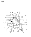
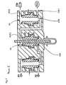
- FIG. 1 is a purely schematic representation of the basic structure of an embodiment of an inventive valve device can be seen.
- a hollow body to be produced for example, from plastic, for example a PET bottle, starting from a blank which is introduced into a blowing cylinder 100, by blowing compressed air and stretch by means of an inserted into the interior of the blank mandrel or stretch rod 102 in a known manner to his desired shape inflated resp. shaped.
- a valve device 103 For supplying the blowing cylinder 100 with the compressed air necessary for this process, a valve device 103 according to the invention is used, which provides the pre-blowing pressure from a pressure source P1 and the actual working or main blowing pressure from a pressure source P2 at the respective pressure level for a respectively adjustable period of time ,
- the size and duration of the Vorblastiks is very important for the blowing process, as this is a correct material distribution of the bladder cylinder arranged blank.
- valve device 103 For the corresponding resp. Dissipation of the working air for this purpose, three switching valves U1, U2, U3 are arranged in the valve device 103.
- the first switching valve U1 is for switching the pressure source, i. the switching from the pressure source P1 as Vorblastik to the pressure source P2 as the main blowing pressure.
- the first input U1E1 of the first changeover valve U1 is connected to the pressure source P1 and the second input U1E2 is connected to the pressure source P2.
- the first input U1E1 is connected to the output U1A. This position is referred to in the present description as a rest position or closed position.
- the switching valve U1 is thus designed as a 3/2-way valve or switch valve, i. there are in total three resp. Outputs two switching states possible, namely either the first input U1E1 to the output U1A (as the closed position) or the second input U1E2 to the output U1A connected (as an open position).
- the terms input and output do not refer to the flow direction of the medium but only to the switching resp. Connection state of the valve.
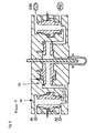
- a piston 2 as an annular piston with a centrally disposed, between the two end faces 4, respectively. 5 of the piston 2 through channel 3, formed.
- the upper end face 4 of the piston 2 opens into a first valve chamber 6 which is likewise formed in the housing 1 and is connected via a pressure line 8 'as an input to an external pressure source 8.
- This pressure source 8 is, for example, at the first pressure level P1.
- the lower end 5 of the piston 2 opens into a second valve chamber 7, in which, for example, centrally the output channel 30 is arranged which forms the output U1A of the changeover valve U1.
- the valve chamber 7 is laterally connected via a pressure line 31 as a second input U1E2 with a further pressure source 32, which is set for example at the second pressure level P2.
- the piston 2 is advantageously formed in the form of an annular piston such that the channel 3 has the largest possible diameter and that the cross section of the channel 3 between the two end faces 4 resp. 5 is constant and straight, advantageously coaxial with the longitudinal axis of the piston 2 extends.
- valve seal 13 is arranged on the upper end face 4 and the lower end face 5 of the piston 2 in each case.
- These valve seals 13 have on their front side in each case a closing surface 14 which in each case closed state of the piston 2 against a correspondingly formed seat surface 15 at the bottom of the respective valve chamber 6, respectively. 7 in sealing stop.
- the piston 2 is at its lower stop, i. the valve seal of the end face 5 is in abutment against the seat surface 15 at the bottom of the lower valve chamber 7 and thus seals the channel 3 and thus also the outlet channel 30 against the lower pressure line 31.
- the output channel 30 is connected via the channel 3 with the upper valve chamber 6 and thus the pressure line 8 'and thus has the pressure level P1.
- the valve seal 13 now further has an active surface 16, i. an arranged between the inner wall of the closing surface 14 and the inner wall of the channel 3 surface, which is smaller than the entire active surface of the upper valve seal 13 of the end face 4 of the piston 2, which is composed of the active surface 16 and the closing surface 14.
- an active surface 16 i. an arranged between the inner wall of the closing surface 14 and the inner wall of the channel 3 surface, which is smaller than the entire active surface of the upper valve seal 13 of the end face 4 of the piston 2, which is composed of the active surface 16 and the closing surface 14.
- this rest position for example, by placing one in the closing direction acting spring can be supported, so that the valve reliably remains in the closed position even in a pressureless state.
- the valve seal 13 is advantageously made of a low-wear, as rigid as possible material and arranged as a separate part on the piston 2.
- a high-strength and temperature-resistant as possible plastic which has a further advantage of damping at a rapid closing movement of the piston 2 and thus on the one hand allows a high closing speed and on the other hand has a high wear resistance.
- valve seal 13 may also be formed as an integrated component directly on the lower end face 5 of the piston 2.
- housing 1 may be made in one piece or in several parts according to the shape and structure of the piston 2, only for the sake of simplicity, the housing 1 is shown in the figures as one piece.
- the two control chambers 11 and 12 are connected to a control pressure source 21.
- the upper control chamber 11 is connected directly to the control pressure source 21, and the lower control chamber 12 is connected to the control pressure source 21 via a control valve 22.
- the control valve 22 In the closed position of the valve, the control valve 22 is closed and designed such that in this closed position, the lower control chamber 12 communicates with the environment is connected, that is vented.
- the upper control chamber 11 is under pressure and the lower control chamber 12 is vented, which keeps the piston 2 in its closed position by the pressure in the control chamber 11 via the first active surface 23.
- the first active surface 23 is geometrically smaller than the second active surface 24 of the piston ring 9 in the lower control chamber 12th
- the lower control chamber 12 is also connected to the control pressure source 21, whereby a differential force between the control chamber 12 and 11 sets up with effect. If this differential force now overcomes the holding force of the piston by the contact pressure of the difference of the active surfaces of the end faces 4 and 5 of the piston 2, the piston 2 responds respectively. the closing surface 14 of the seat surface 15 in the lower valve chamber 7 and the piston 2 is moved upward. Due to the geometric design of the end faces 4 and 5 of the piston 2, respectively. the corresponding active surfaces are now formed immediately after lifting the lower valve seal 13 equal effective areas. Thus, only a small force for a quick, complete opening of the valve, ie complete movement of the piston 2 in its upper end position, as in FIG. 2 shown, needed.
- the valve works as a switching valve between the two Pressure levels P1 and P2. Due to the very fast switching times of the valve, ie the rapid movement of the piston 2 between its two positions, can in the pressure lines 31 rep. 8 'are usually dispensed with the arrangement of check valves.
- the piston 2 has very good damping properties, since he responds at its two end faces 4 respectively. 5 is very well cushioned over the valve seals 13.
- valve arrangement Another advantage of this valve arrangement is that, for reliable operation of the switching valve, i. for the opening and closing of the piston 2, no working pressure on the part of the external pressure sources 8 resp. 32 is necessary, i. the valve works even with a very low control pressure level. Since no pressure difference between the first valve chamber 6 and the second valve chamber 7 is necessary, the valve can also be controlled when the two valve chambers 6 and 7 are virtually no pressure or have the same pressure level.
- the inventive valve device according to FIG. 1 has in the dining area, the first switching valve U1, wherein the Output U1A is arranged in the region of the valve space of the second input U1E2, which is connected to the pressure source P2. In this way, short connecting distances are realized, in particular for the main blowing process, which leads to small losses and thus high efficiency.
- the second switching valve U2 is arranged directly in the region of the blowing cylinder 100, wherein the output U2A opens directly into the blowing volume of the blowing cylinder 100.
- the output U2A is advantageously arranged in the region of the valve space of the first input U2E1, which is connected to the output U1A of the first changeover valve U1.
- the necessary for the manufacturing process of the hollow body stretch rod 102 is guided coaxially with the piston 2 of the switching valve U2.
- the second input U2E2 serves as a vent outlet and is connected to the output U3A of the third switching valve U3.
- the first input U3E1 of the third switching valve U3 is connected to the environment EXH, for example via a silencer, while the second input U3E2 is connected to a pressure feedback system REC.
- the pressure recirculation system REC the used compressed air is recuperated at high pressure level after the blowing process as a saving process, before the residual air is released to the environment.
- the output U3A is arranged in the region of the valve space of the second input U3E2, as a result of which the economy process can also be carried out very efficiently by means of short connection paths.
- FIG. 3 illustrated blow curve for the entire blowing process of a single hollow body realize.
- the valve movements of the three changeover valves U1, U2 and U3 are shown, wherein the respective curve, the position of the piston down resp. above according to the illustration of FIG. 1 shows.
- the lower position of the piston represents the rest position or closed position and the upper position represents the open position of the reversing valve.
- a pre-blowing pressure P1 of 10 bar and a main blowing pressure P2 of 40 bar are used.
- the pre-blowing pressure P1 is reached after the opening of the second switching valve U2 and held until the end of the pre-blowing time Tv.
- the main blowing phase is started at a working pressure P2 of about 40 bar and held until the end of the main blowing time Th.
- the third switching valve U3 is opened to prepare the connection to REC.
- the second switching valve U2 is closed again, which leads to a pressure reduction in the blowing cylinder 100 via the pressure feedback system REC.
- a big advantage with this arrangement is that by the arrangement of three switching or switch valves U1, U2 resp. U3 all valve functions can be realized easily and with short connection paths, whereby harmful dead space is avoided by additional valves or lines, especially as can be dispensed with the use of check valves in the rule.
- a not inconsiderable saving in compressed air can advantageously be achieved.
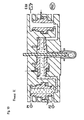
- FIGS. 4 to 7 show still schematically the corresponding piston positions of the three valves U1, U2 and U3 in the various process phases V, H, S and E.
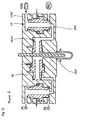
- FIG. 8 shows schematically in longitudinal section an alternative embodiment of a valve device according to the invention.
- the difference to the embodiment according to FIG. 1 lies in a different arrangement of the output U2A of the second switching valve U2, the other two switching valves U1 and U3 are identically arranged and designed as in FIG. 1 shown and described.
- the output U2A is arranged in the middle region of the reversing valve U2 and leads radially away from the piston axis toward the blowing cylinder 100.
- the stretch rod 102 is arranged coaxially with the output U2A and thus aligned substantially perpendicular to the piston axis of the switching valve U2.
- the stretch rod 102 penetrates the piston chamber of the Change-over valve U2 right-angled and not coaxial.
- the piston of the switching valve U2 two radially opposite slots, respectively. Recesses, through which the stretch rod 102 is guided and through which the pressure from the cavity of the piston can flow into the output U2A.
- valve function of the reversing valve U2 remains identical to the previously described function with reference to FIG. 1 , Again, the show FIGS. 9 to 12 the respective positions of the pistons of the changeover valves U1, U2 and U3 in the process phases V, H, R and S.
Abstract
Description
Die vorliegende Erfindung betrifft eine Ventileinrichtung nach dem Oberbegriff von Anspruch 1 sowie ein Verfahren nach dem Oberbegriff von Anspruch 11.The present invention relates to a valve device according to the preamble of
Eine solche Ventllenrichtung und ein solches Verfehren ist aus dem Dokument
Für die Herstellung von Kunststoffflaschen, insbesondere von PET-Flaschen, wird ein Rohling oder Vorformling in einer Hohlkörperblasmaschine in einem Blaszylinder in der Regel in zwei Schritten in seine endgültige Form aufgeblasen. Hierfür weist der Rohling bereits im Wesentlichen den fertigen Flaschenkopf auf, welcher in der Blasform der Hohlkörperblasmaschine gehalten und mit einem Druckluftsystem verbunden wird. Durch Einblasen von Druckluft durch den Flaschenkopf wird der Rohling aufgeblasen und schliesslich in seine endgültige Form gebracht.For the production of plastic bottles, in particular of PET bottles, a blank or preform is blown in a blow molding machine in a blow cylinder usually in two steps in its final form. For this purpose, the blank already substantially on the finished bottle head, which is held in the blow mold of the blow molding machine and connected to a compressed air system. By blowing compressed air through the bottle head, the blank is inflated and finally brought to its final shape.
Der eigentliche Blasprozess wird damit in einem zweistufigen Verfahren ausgeführt, wobei zuerst ein Vorblasen mit einem Druckwert zwischen 2 bis 20 bar über ein Vorblasventil erfolgt, und danach das Fertigblasen, d.h. das endgültige Formen der Kunststoffflasche zu ihrer Endform, mit einem Druckwert zwischen 15 bis 40 bar über ein Hauptblasventil erfolgt. Diese beiden Ventile sind jeweils mit einer Druckquelle mit dem entsprechenden Druckpotential verbunden.The actual blowing process is thus carried out in a two-stage process, wherein first a pre-blowing takes place with a pressure value between 2 to 20 bar via a Vorblasventil, and then the final blowing, i. the final shaping of the plastic bottle to its final shape, with a pressure between 15 to 40 bar via a main blow valve. These two valves are each connected to a pressure source with the corresponding pressure potential.
Anschliessend an diese beiden Blasstufen muss der Druck aus der Kunststoffflasche und aus den Zuführkanälen abgelassen werden, bevor die Kunststoffflasche von der mit dem Blaszylinder verbundenen Blasform entfernt werden kann. Dieser Prozessschritt wird auch als Entlüftung bezeichnet.Following these two blowing stages, the pressure must be released from the plastic bottle and from the feed channels before the plastic bottle separates from the plastic bottle Blowing cylinder connected blow mold can be removed. This process step is also referred to as venting.
Diese Entlüftung erfolgt herkömmmlicherweise über ein Entlüftungsventil, welches mit dem Blaszylinder verbunden ist und in geöffneter Stellung die Druckluft in die Umgebung abgibt.This venting is done conventionally via a vent valve, which is connected to the blow cylinder and emits the compressed air into the environment in the open position.
Da das Druckniveau und die Luftmenge für den Blasprozess mittels einer Druckerzeugungseinrichtung generiert werden müssen, bedeutet das Abblasen dieser Luftmenge in die Umgebung ein entsprechend grosser Energieverlust.Since the pressure level and the amount of air for the blowing process must be generated by means of a pressure generating device, blowing off this amount of air into the environment means a correspondingly large energy loss.
Es sind nun auch Vorrichtungen und Verfahren bekannt, um wenigstens einen Teil dieser Restluft wieder zurückzugewinnen und als Prozessluft einzusetzen.Devices and methods are now also known in order to recover at least part of this residual air and to use it as process air.
Beispielsweise sind Ventileinrichtungen bekannt, bei welchen eine Teilrückgewinnung der Druckluft über ein separates Ventil, welches zwischen dem Blaszylinder und dem Entlüftungsventil angeordnet ist, realisiert wird. Dabei muss dieses zusätzliche Ventil allerdings separat angesteuert werden und bildet selbst wieder zusätzlichen Totraum, welcher gefüllt werden muss und dessen Restvolumen über das Entlüftungsventil in die Umgebung abgegeben werden muss.For example, valve devices are known in which a partial recovery of the compressed air via a separate valve, which is arranged between the blowing cylinder and the vent valve is realized. However, this additional valve must be controlled separately and forms itself again additional dead space, which must be filled and the residual volume must be discharged through the vent valve into the environment.
In diesem Zusammenhang wird festgehalten, dass als Totraum die Leitungen und Räume zwischen den eigentlichen Ventilen und dem Blaszylinder inklusive der Kanäle im Blaszylinder selbst bezeichnet werden. Der gesamte Arbeitsraum besteht aus diesem Totraum zusammen mit dem Volumen des Hohlkörpers, dessen Inhalt am Schluss des Blasprozesses dem Umgebungsdruck angepasst werden muss. Als Füllvolumen wird die Menge Druckluft im Arbeitsraum bezeichnet.In this context, it is stated that the lines and spaces between the actual valves and the blow cylinder including the channels in the blow cylinder itself are referred to as dead space. The entire working space consists of this dead space together with the volume of the hollow body whose content at the end of the blowing process the Ambient pressure must be adjusted. The filling volume is the amount of compressed air in the working space.
Die Aufgabe der vorliegenden Erfindung bestand nun darin, eine Ventileinrichtung zu finden, welche mit möglichst wenig aktiven Komponenten einen effizienten und schnellen Blas- und Entlüftungsvorgang ermöglicht.The object of the present invention was to find a valve device which allows with as few active components an efficient and fast blowing and venting process.
Diese Aufgabe wird erfindungsgemäss durch eine Ventileinrichtung mit den Merkmalen nach Anspruch 1 gelöst. Weitere, erfindungsgemässe Ausführungsformen ergeben sich aus den Merkmalen der weiteren Ansprüche 2 bis 10.This object is achieved by a valve device with the features of
Die erfindungsgemässe Ausführung betrifft eine Ventileinrichtung für Hohlkörperblasmaschinen zum Einblasen von Druckluft in ein Blasvolumen eines Vorformlings, mit einer ersten Druckspeisung und einer zweiten Druckspeisung, wobei die erste Druckspeisung ein tieferes Druckniveau aufweist als die zweite Druckspeisung, und mit über Ventile absperrbare Zu- und Ableitungen zum Blasvolumen. Erfindungsgemäss weist die Ventileinrichtung drei Umschaltventile auf, ein erstes Umschaltventil mit zwei Eingängen und einem Ausgang auf, wobei der erste Eingang mit der ersten Druckspeisung und der zweite Eingang mit der zweiten Druckspeisung verbunden ist und der Ausgang mit einem ersten Eingang eines zweiten Umschaltventils verbunden ist, dessen Ausgang mit dem Blasvolumen in Verbindung steht, und ein zweiter Eingang des zweiten Umschaltventils mit dem Ausgang eines dritten Umschaltventils in Verbindung steht, dessen erster Eingang mit der Umgebung und dessen zweiter Eingang mit einem Druckrückführungssystem verbunden ist, wobei die Umschaltventile einen als Hohlkörper ausgebildeten Ventilkolben aufweisen, dessen Hohlraum permanent offen mit dem Ausgang des jeweiligen Umschaltventils verbunden ist. Mit dieser Anordnung lassen sich mit einer auf drei Ventile reduzierten Ventileinrichtung alle notwendigen Prozessschritte des Blasvorganges einfach steuern, d.h. der Vorblasprozess, der Hauptblasprozess, der Sparprozess und der Entlüftungsprozess.The inventive embodiment relates to a valve device for hollow-core blow molding machines for blowing compressed air into a blowing volume of a preform, with a first pressure supply and a second pressure supply, wherein the first pressure supply has a lower pressure level than the second pressure supply, and shut off via valves inlet and outlet lines to blowing volume. According to the invention, the valve device has three changeover valves, a first changeover valve with two inputs and one output, wherein the first input is connected to the first pressure feed and the second input is connected to the second pressure feed and the output is connected to a first input of a second changeover valve, the output of which communicates with the blowing volume, and a second input of the second switching valve communicates with the output of a third switching valve whose first input is connected to the environment and the second input is connected to a pressure feedback system, the Change-over valves have a hollow piston designed as a valve piston, the cavity is permanently open connected to the output of the respective switching valve. With this arrangement, with a valve device reduced to three valves, all the necessary process steps of the blowing process can be easily controlled, ie the pre-blowing process, the main blowing process, the economy process and the deaeration process.
Als Umschaltventil wird hier ein Ventil bezeichnet, welches insgesamt drei Anschlüsse bei zwei möglichen Ventil- resp. Schaltstellungen aufweist, ein solches Ventil wird in der Fachwelt auch als 3/2-Wegventil bezeichnet. Im vorliegenden Fall werden alternativ der erste Eingang oder der zweite Eingang jeweils mit dem Ausgang verbunden; d.h. es wird in der Funktion als Weiche eingesetzt. Es ist hier klar festzuhalten, dass die Bezeichnung Eingang und Ausgang nicht die Fliessrichtung des durch das Ventil zu steuernden Mediums angibt, d.h. es ist ein Durchfliessen sowohl von Eingang zu Ausgang wie auch von Ausgang zu Eingang möglich.As a switching valve is here called a valve, which is a total of three connections in two possible valve resp. Having switch positions, such a valve is referred to in the art as a 3/2-way valve. In the present case, alternatively, the first input or the second input are respectively connected to the output; i.e. it is used in the function as a switch. It should be clearly noted here that the term input and output does not indicate the direction of flow of the medium to be controlled by the valve, i. it is possible to flow both from input to output as well as from output to input.
Beispielsweise ist der Ventilkolben der Umschaltventile als im jeweiligen Ventilkörper längsverschiebbarer zylindrischer Kolben ausgebildet, welcher einen radial nach Aussen abragenden, zwischen den beiden Stirnflächen des Kolbens angeordneten Kolbenring aufweist, dessen beide Stirnflächen jeweils in einer ersten Steuerkammer und einer zweiten Steuerkammer liegen. Damit lassen sich schnell agierende, d.h. schnell von einer Schaltposition in die andere Schaltposition steuerbare Umschaltventile realisieren, die sowohl die hohen Druckwerte der Blasluft auf den beiden Stufen verarbeiten können wie auch das Steuern der verbrauchten Luft im Entlüftungsprozess bis auf praktisch Umgebungsdruck hinunter. Weiter erlaubt diese Ausbildung des Kolbens eine sehr kompakte und platzsparende Bauweise und dank der aussenliegenden Steuerkammern mit verhältnismässig grossen Steuerflächen verhältnismässig kleine Steuerdrücke für die Steuerung des Kolbens und damit des Ventils an sich. Durch die Anordnung und Dimensionierung der Wirkflächen des Kolbens wird dieser durch den Arbeitsdruck im Ventil selbst bei seiner Bewegung unterstützt, was zu sehr schnellen Öffnung resp. Schliesszeiten führt.For example, the valve piston of the switching valves is designed as a longitudinally displaceable in the respective valve body cylindrical piston, which has a radially outwardly projecting, arranged between the two end faces of the piston piston ring whose two end faces each lie in a first control chamber and a second control chamber. This makes it possible to realize fast-acting switching valves which can be controlled quickly from one switching position to the other switching position and which can handle both the high pressure values of the blast air on the two stages as well as controlling the used air in the deaeration process down to practically ambient pressure. Next, this design of the piston allows a very compact and space-saving design and thanks to the outer control chambers with relatively large control surfaces relatively small control pressures for the control of the piston and thus the valve itself. Due to the arrangement and dimensioning of the active surfaces of the piston this is supported by the working pressure in the valve itself during its movement, resulting in very rapid opening respectively. Closing times leads.
Beispielsweise ist eine erste Wirkfläche des Kolbenringes in der ersten Steuerkammer kleiner als eine zweite Wirkfläche des Kolbenringes in der zweiten Steuerkammer. Das Verhältnis der Wirkflächen wird vorteilhaft derart gewählt, dass ein Verhältnis von ca. 80% erreicht wird, d.h. dass die Wirkfläche in der einen Steuerkammer nur ca. 80% der Wirkfläche in der anderen Steuerkammer des Kolbenringes beträgt.For example, a first effective area of the piston ring in the first control chamber is smaller than a second effective area of the piston ring in the second control chamber. The ratio of the effective areas is advantageously chosen such that a ratio of approximately 80% is achieved, i. that the effective area in the one control chamber is only about 80% of the effective area in the other control chamber of the piston ring.
Beispielsweise steht die erste Steuerkammer über eine erste Steuerdruckleitung mit einem Steuerdruckreservoir in Verbindung und steht die zweite Steuerkammer über ein Steuerventil schaltbar entweder mit der Umgebung oder mit dem Steuerdruckreservoir in Verbindung. Beispielsweise ist das Steuerventil als sogenanntes 3/2-Ventil ausgelegt, d.h. es weist drei Anschlüsse bei zwei Schaltzuständen auf. Vorteilhaft kann hier ein einfach aufgebautes und mit einem niedrigen Steuerdruckniveau zu betreibendes Ventil eingesetzt werden, welches dank kleinen Dimensionen auch platzsparend ausgeführt werden kann.For example, the first control chamber communicates via a first control pressure line with a control pressure reservoir and the second control chamber is connected via a control valve switchable either to the environment or to the control pressure reservoir. For example, the control valve is designed as a so-called 3/2 valve, ie it has three connections in two switching states. Advantageously, here a simple design and with a low control pressure level to be operated valve can be used, which can also be designed to save space thanks to small dimensions.
Beispielsweise ist an beiden Stirnseiten der Kolben jeweils eine ringförmige axial ausgerichtete Ventildichtung angeordnet, deren Stirnfläche die jeweilige Schliessfläche des Kolbens bildet und in geschlossenem Zustand des Kolbens gegen eine Sitzfläche des entsprechenden Ventilraumes in Anschlag steht und es ist weiter in geschlossenem Zustand eine gegen die Schliessrichtung wirkende Wirkfläche gebildet, wobei die geometrischen Abmessungen der beiden Ventildichtungen identisch sind. Durch diesen Aufbau kann eine einfache Steuerung des Kolbens über die beiden Steuerkammern des Kolbenringes erfolgen, wobei die Steuerkräfte verhältnismässig klein ausfallen können und damit ein herkömmliches, einfaches Steuerventil eingesetzt werden kann. Da die entsprechenden Steuerflächen radial vom Kolben nach Aussen abragend angeordnet sind, weisen sie einerseits kompakte Abmessungen bei trotzdem grossen Wirkflächen auf. Durch die Dimensionierung der Wirkflächen des Kolbens wird dieser durch den Arbeitsdruck selbst beim Öffnen unterstützt, was zu sehr schnellen Öffnung resp. Schliesszeiten führt.For example, an annular axially oriented valve seal is arranged on both end faces of the piston, whose end face forms the respective closing surface of the piston and in the closed state of the piston against a seat surface of the corresponding valve chamber into abutment and it is further in the closed state acting against the closing direction Formed effective area, the geometric dimensions of the two valve seals are identical. By this construction, a simple control of the piston via the two control chambers of the piston ring can take place, wherein the control forces can be relatively small and thus a conventional, simple control valve can be used. Since the corresponding control surfaces are arranged protruding radially from the piston to the outside, on the one hand they have compact dimensions with nevertheless large effective surfaces. By dimensioning the active surfaces of the piston this is supported by the working pressure even when opening, resulting in very fast opening respectively. Closing times leads.
Beispielsweise weisen die Ventildichtungen des Kolbens als Schliesskante einen runden Flansch mit im Wesentlichen gerader Schliessfläche auf, wobei die Schliessfläche vorzugsweise senkrecht zur Schliessrichtung des Hohlkolbens ausgerichtet ist. Damit wird eine gute Dichtwirkung bei grossem Öffnungsquerschnitt erreicht. Die Schliessfläche beträgt dabei vorteilhaft zwischen 5% - 25% der Wirkfläche der entsprechenden Stirnseite des Kolbens. Beim Öffnen des Ventils, d.h. beim Abheben des Kolbens resp. der Ventildichtung von ihrem Sitz wird das Ventil praktisch unmittelbar vollständig druckkompensiert, da die beiden Wirkflächen der beiden Stirnseiten des Kolbens nun praktisch gleich gross sind, wodurch die Bewegungskraft für den Kolben sinkt und damit eine hohe Kolbengeschwindigkeit d.h. Öffnungsgeschwindigkeit des Ventils erzielt wird.For example, the valve seals of the piston as Schliesskante a round flange with a substantially straight closing surface, wherein the closing surface is preferably aligned perpendicular to the closing direction of the hollow piston. This achieves a good sealing effect with a large opening cross section. The closing surface is advantageously between 5% - 25% of the effective area the corresponding end face of the piston. When opening the valve, ie when lifting the piston resp. the valve seal from its seat, the valve is practically completely directly pressure compensated, since the two active surfaces of the two end faces of the piston are now practically the same size, whereby the motive power for the piston decreases and thus a high piston speed, ie opening speed of the valve is achieved.
Beispielsweise ist dabei die Aussenfläche des Flansches zur Schliessfläche hin radial nach innen angeschrägt ausgeführt. Das bedeutet, dass der Flansch in Richtung der Schliessfläche angefast ist. Damit wird eine Wirkfläche geschaffen, die durch den im entsprechenden äusseren Ventilraum herrschenden Druck ein in Öffnungsrichtung gerichtete Kraft auf den Kolben ausüben kann. Damit kann beispielsweise eine Überdruck-Notöffnung realisiert werden, die den Kolben anhebt, wenn das Druckniveau resp. die Druckdifferenz in Bezug auf den Druck im inneren Ventilraum resp. im Kanal des Kolbens einen bestimmten Wert überschreitet.For example, the outer surface of the flange is designed to be tapered radially inward toward the closing surface. This means that the flange is chamfered in the direction of the closing surface. Thus, an active surface is created, which can exert a force directed in the opening direction of the piston by the pressure prevailing in the corresponding outer valve space. Thus, for example, an overpressure emergency opening can be realized, which raises the piston when the pressure level resp. the pressure difference with respect to the pressure in the inner valve chamber resp. in the channel of the piston exceeds a certain value.
Beispielsweise sind der Kolben und die Ventildichtung zweiteilig aus unterschiedlichen Materialien ausgebildet, wobei die Ventildichtung vorzugsweise aus Kunststoff besteht. Damit kann der Kolben beispielsweise aus Metall mit verhältnismässig geringen Wandstärken gefertigt sein und die Ventildichtung kann einfach auf entsprechende ausgebildete Stirnflächen des Kolbens aufgesteckt und damit verbunden werden. Zudem weist damit die Ventildichtung vorteilhaft sehr gute Dämpfungseigenschaften beim Schliessen des Kolbens in seinen jeweiligen Ventilsitz auf.For example, the piston and the valve seal are formed in two parts of different materials, wherein the valve seal is preferably made of plastic. Thus, the piston can be made for example of metal with relatively small wall thicknesses and the valve seal can be easily attached to corresponding trained end faces of the piston and connected to it. In addition, it shows the valve seal advantageous very good damping properties when closing the piston in its respective valve seat.
Beispielsweise sind beide Eingänge des ersten Umschaltventils direkt ohne Rückschlagventil mit der ersten resp. der zweiten Druckspeisung verbunden. Durch die schnelle Umschaltzeit des Kolbens wird praktisch keine resp. nur eine äusserst geringe Überlappung der beiden Eingänge verursacht, d.h. die direkte Verbindung zwischen den beiden Eingängen ist derart kurz, dass sie in der Regel vernachlässigt werden kann. Vorteilhaft ist der Ausgang des ersten Umschaltventils im Bereich der Ventildichtung des Eingangs der höheren Druckquelle angeordnet, so dass der höhere Druck zuerst den Hohlraum des Ventilkolbens durchlaufen muss, bevor er zum ersten Eingang mit der niedrigeren Druckquelle gelangt.For example, both inputs of the first switching valve directly without check valve with the first resp. connected to the second pressure supply. Due to the fast switching time of the piston is practically no resp. causes only a very small overlap of the two inputs, i. The direct connection between the two inputs is so short that it can usually be neglected. Advantageously, the output of the first switching valve is arranged in the region of the valve seal of the input of the higher pressure source, so that the higher pressure must first pass through the cavity of the valve piston before it reaches the first input with the lower pressure source.
Beispielsweise ist durch den Ventilkolben des zweiten Umschaltventils hindurch eine Reckstange der Hohlkörperblasmaschine, koaxial oder annähernd senkrecht zur Längsachse des Ventilkolbens verlaufend und den Hohlraum des Ventilkolbens durchdringend, angeordnet. Damit lässt sich das zweite Umschaltventil besonders platzsparend unmittelbar im Blaskopf der Hohlkörperblasmaschine im Bereich des Vorformlings anordnen, was auch zu sehr kurzen Strömungskanälen für die Blasluft und damit entsprechend kleinen Verlusten führt.For example, a stretching rod of the hollow-body blowing machine, extending coaxially or approximately perpendicular to the longitudinal axis of the valve piston and penetrating the cavity of the valve piston, is arranged through the valve piston of the second change-over valve. Thus, the second changeover valve can be arranged in a particularly space-saving manner directly in the blow head of the blow molding machine in the region of the preform, which also leads to very short flow channels for the blown air and thus correspondingly small losses.
Die Aufgabe wird weiter erfindungsgemäss durch ein Verfahren mit den Merkmalen nach Anspruch 11 gelöst. Weitere, erfindungsgemässe Ausführungsformen des Verfahrens ergeben sich aus den Merkmalen der weiteren Ansprüche 12 bis 14.The object is further achieved according to the invention by a method having the features of
Beim vorliegenden Verfahren zum Einblasen von Druckluft in ein Blasvolumen eines Vorformlings unter Verwendung von Druckluft, welche in zwei unterschiedlichen Druckniveaus bereitgestellt wird, wobei das Blasvolumen zuerst mit dem ersten, tieferen Druckniveau und danach mit dem zweiten, höheren Druckniveau gesteuert über Ventile beaufschlagt wird und nach abgeschlossenem Blasvorgang der im Blasvolumen befindliche Druck gesteuert über ein Entlüftungsventil in die Umgebung abgeführt wird, wird erfindungsgemäss die Zufuhr der Druckluft der beiden unterschiedlichen Druckniveaus über ein erstes Umschaltventil gesteuert. Weiter wird die Druckluftzufuhr zum Blasvolumen und Abführung nach abgeschlossenem Blasvorgang aus dem Blasvolumen über ein zweites Umschaltventil gesteuert und die vom zweiten Umschaltventil abgeführte verbrauchte Luft über ein drittes Umschaltventil gesteuert an die Umgebung oder in ein Druckrückführungssystem zugeführt. Dabei wird vor Beginn des Blasvorganges die Ventileinrichtung entlüftet geschaltet, d.h. das zweite Umschaltventil und das dritte Umschaltventil miteinander verbunden und das dritte Umschaltventil mit der Umgebung sowie das erste Umschaltventil mit dem tieferen Druckniveau verbunden geschaltet. In dieser Stellung der Ventileinrichtung ist das Blasvolumen druckfrei und somit kann beispielsweise ein neuer Vorformling in die Blasstation eingebracht und mit der Ventileinrichtung verbunden werden resp. ein fertig geblasener Hohlkörper aus der Blasstation entfernt werden, da diese in dieser Stellung druckfrei ist. Für den Start des Blasvorganges wird nun das zweite Umschaltventil mit dem ersten Umschaltventil verbindend geschaltet, womit der Vorblasdruck in das Blasvolumen eingeblasen wird. Nach Ablauf einer vordefinierten resp. eingestellten Vorblaszeit wird das erste Umschaltventil mit dem höheren Druckniveau verbindend umgeschaltet, d.h. nun wird das Blasvolumen mit dem zweiten, höheren Druck, dem Hauptblasdruck, beaufschlagt. Nach Ablauf einer vordefinierten resp. eingestellten Hauptblaszeit wird das zweite Umschaltventil mit dem dritten Umschaltventil verbindend umgeschaltet. Damit hat der Vorformling nun seine endgültige Form erreicht und die Zufuhr des Hauptblasdruckes zum Blasvolumen kann unterbrochen werden. Nach dem Umschalten des zweiten Umschaltventils kann nun das erste Umschaltventil mit dem tieferen Druckniveau verbinden zurückgeschaltet werden. Der Teil des in den Leitungen der Ventileinrichtung verbleibenden hohen Druckanteils wird in der Regel problemlos im unteren Druckniveau aufgenommen, da es sich um äusserst kleine Volumen handelt. Selbstverständlich kann im ersten Eingang zum ersten Umschaltventil aber auch ein Rückschlagventil angeordnet werden, so dass keine hohen Druckstösse in das Vorblassystem gelangen können. Nach Ablauf einer vordefinierten resp. eingestellten Rekuperationszeit wird das dritte Umschaltventil mit der Umgebung verbindend geschaltet, womit die Ventileinrichtung entlüftet geschaltet ist. Vor diesem Umschalten des dritten Umschaltventils gelangt der gebrauchte Druck in das Druckrückführungssystem, womit dieser Druckluftanteil nicht verloren geht sondern wieder für den Blasprozess oder für andere Prozesse verwendet werden kann. Nur der noch verbleibende Druckanteil wird schliesslich an die Umgebung abgegeben.In the present method for injecting compressed air into a blown volume of a preform using compressed air which is provided at two different pressure levels, the blow volume is first applied to the first, lower pressure level and then to the second, higher pressure level controlled by valves and after controlled blowing process of the pressure located in the blowing volume controlled by a vent valve is discharged into the environment, the supply of compressed air of the two different pressure levels is controlled according to the invention via a first switching valve. Further, the compressed air supply to the blowing volume and discharge after complete blowing from the blowing volume is controlled via a second switching valve and the discharged from the second switching valve spent air via a third switching valve controlled supplied to the environment or in a pressure feedback system. In this case, the valve device is switched vented before the start of the blowing process, that is, the second switching valve and the third switching valve connected to each other and the third switching valve connected to the environment and the first switching valve connected to the lower pressure level. In this position of the valve device, the blowing volume is pressure-free and thus, for example, a new preform can be introduced into the blowing station and connected to the valve device, respectively. a finished blown hollow body are removed from the blowing station, because this is pressure-free in this position. For the start of the blowing process, the second switching valve is now connected to the first switching valve connecting, whereby the Vorblasdruck is blown into the blowing volume. After expiration of a predefined resp. set Vorblaszeit the first switching valve with the higher pressure level is switched connecting, ie now the blow volume with the second, higher pressure, the main blow pressure applied. After expiration of a predefined resp. set main blowing time, the second switching valve is switched to the third switching valve connecting. Thus, the preform has now reached its final shape and the supply of the main blowing pressure to Blasvolumen can be interrupted. After switching over the second changeover valve, the first changeover valve can now be switched back to the lower pressure level. The part of the remaining in the lines of the valve device high pressure component is usually easily absorbed in the lower pressure level, since it is extremely small volume. Of course, in the first input to the first switching valve but also a check valve can be arranged so that no high pressure surges can get into the Vorblassystem. After expiration of a predefined resp. set recuperation time, the third switching valve is connected to the environment connecting, whereby the valve device is connected vented. Before this switching of the third switching valve, the used pressure enters the pressure feedback system, so this compressed air component is not is lost but can be used again for the blowing process or for other processes. Only the remaining pressure is finally released to the environment.
Es hat sich gezeigt, dass damit Einsparungen in der Bereitstellung der Druckluft von bis zu 10% - 25% realisiert werden können. Es ist für den Fachmann klar, dass die Vorblaszeit und Hauptblaszeit entsprechend den Materialeigenschaften des Hohlkörpers sowie dessen Formgebung gewählt resp. eingestellt werden, um in möglichst kurzer Produktionszeit eine optimale Formgebung und definierte Materialeigenschaften erzielt werden.It has been shown that savings in compressed air supply of up to 10% - 25% can be achieved. It is clear to those skilled in the art that the Vorblaszeit and Hauptblasblaszeit selected according to the material properties of the hollow body and its shape resp. be set in order to achieve optimum shaping and defined material properties in the shortest possible production time.
Beispielsweise wird das erste Druckniveau auf einen Druck zwischen 4 bis 20 bar eingestellt resp. geregelt, d.h. ein Vorblasdruck in dieser Grösse bereitgestellt.For example, the first pressure level is set to a pressure between 4 to 20 bar resp. regulated, i. a Vorblasdruck provided in this size.
Beispielsweise wird das zweite Druckniveau auf einen Druck zwischen 15 bis 40 bar eingestellt resp. geregelt, d.h. ein Hauptblasdruck in dieser Grösse bereitgestellt, beispielsweise durch eine mehrstufige Kompressoranlage.For example, the second pressure level is set to a pressure between 15 to 40 bar resp. regulated, i. a Hauptblasdruck provided in this size, for example by a multi-stage compressor system.
Beispielsweise wird die Rekuperationszeit durch Messung des Druckes im Blaszylinder und Erreichen resp. Unterschreiten eines bestimmten Druckwertes dynamisch bestimmt. Das heisst, dass in Abhängigkeit des Verlaufes des Druckabbaus des Füllvolumens das Entlüftungsventil beim Erreichen resp. Unterschreiten eines bestimmten Druck-Grenzwertes geöffnet wird.For example, the recuperation time by measuring the pressure in the blow cylinder and reaching resp. Falling below a certain pressure value determined dynamically. This means that depending on the course of the pressure reduction of the filling volume, the vent valve when reaching resp. Falling below a certain pressure limit is opened.
Ausführungsbeispiele der vorliegenden Erfindung werden nachstehend anhand von Figuren noch näher erläutert. Es zeigen
-
Fig. 1 schematisch den Längsschnitt durch eine erfindungsgemässe Ventileinrichtung für das Blasen von Kunststoffflaschen, mit den Ventilen geschaltet in der entlüfteten Ausgangsstellung A; -
Fig. 2 schematisch den detaillierteren Längsschnitt durch ein erfindungsgemäss ausgestaltetes Umschaltventil; -
Fig. 3 schematisch den Druckverlauf innerhalb des Blasvolumens über den gesamten Blasprozess einer erfindungsgemässen Ventileinrichtung; -
Fig. 4 denLängsschnitt nach Figur 1 mit den Ventilstellungen in der Vorblasphase; -
Fig. 5 denLängsschnitt nach Figur 1 mit den Ventilstellungen in der Hauptblasphase H; -
Fig. 6 denLängsschnitt nach Figur 1 mit den Ventilstellungen in der Rekuperationsphase R; -
Fig. 7 denLängsschnitt nach Figur 1 mit den Ventilstellungen in der Entlüftungsphase E; -
Fig. 8 schematisch den Längsschnitt durch eine alternative erfindungsgemässe Ventileinrichtung für das Blasen von Kunststoffflaschen, mit den Ventilen geschaltet in der entlüfteten Ausgangsstellung A; -
Fig. 9 denLängsschnitt nach Figur 8 mit den Ventilstellungen in der Vorblasphase V; -
Fig. 10 denLängsschnitt nach Figur 8 mit den Ventilstellungen in der Hauptblasphase H; -
Fig. 11 denLängsschnitt nach Figur 8 mit den Ventilstellungen in der Rekuperationsphase R; -
Fig. 12 denLängsschnitt nach Figur 8 mit den Ventilstellungen in der Entlüftungsphase E.
-
Fig. 1 schematically the longitudinal section through an inventive valve means for the blowing of plastic bottles, connected with the valves in the vented starting position A; -
Fig. 2 schematically the more detailed longitudinal section through an inventively ausgestaltetes switching valve; -
Fig. 3 schematically the pressure curve within the blast volume over the entire blowing process of a valve device according to the invention; -
Fig. 4 the longitudinal section afterFIG. 1 with the valve positions in the Vorblasphase; -
Fig. 5 the longitudinal section afterFIG. 1 with the valve positions in the main blowing phase H; -
Fig. 6 the longitudinal section afterFIG. 1 with the valve positions in the recuperation phase R; -
Fig. 7 the longitudinal section afterFIG. 1 with the valve positions in the venting phase E; -
Fig. 8 schematically the longitudinal section through an alternative inventive valve device for the blowing of plastic bottles, connected to the valves in the vented starting position A; -
Fig. 9 the longitudinal section afterFIG. 8 with the valve positions in the Vorblasphase V; -
Fig. 10 the longitudinal section afterFIG. 8 with the valve positions in the main blowing phase H; -
Fig. 11 the longitudinal section afterFIG. 8 with the valve positions in the recuperation phase R; -
Fig. 12 the longitudinal section afterFIG. 8 with the valve positions in the venting phase E.
Aus
Ein beispielsweise aus Kunststoff herzustellender Hohlkörper, beispielsweise eine PET-Flasche, wird ausgehend von einem Rohling, der in einem Blaszylinder 100 eingebracht ist, durch Einblasen von Druckluft und strecken mittels eines in das Innere des Rohlings eingeführten Streckdorns oder Reckstange 102 in bekannter Weise zu seiner gewünschten Form aufgeblasen resp. geformt.A hollow body to be produced, for example, from plastic, for example a PET bottle, starting from a blank which is introduced into a
Für die Versorgung des Blaszylinders 100 mit der für diesen Prozess notwendigen Druckluft wird eine erfindungsgemässe Ventileinrichtung 103 verwendet, welche den Vorblasdruck aus einer Druckquelle P1 und den eigentlichen Arbeits- oder Hauptblasdruck aus einer Druckquelle P2 auf dem jeweiligen Druckniveau für eine jeweils einstellbare Zeitdauer zur Verfügung stellt. Insbesondere die Grösse und Dauer des Vorblasdrucks ist für den Blasprozess sehr wichtig, da hierdurch eine korrekte Materialverteilung des im Blaszylinder angeordneten Rohlings erfolgt.For supplying the
Für die entsprechend Zu- resp. Abführung der Arbeitsluft sind hierfür in der Ventileinrichtung 103 drei Umschaltventile U1, U2, U3 angeordnet.For the corresponding resp. Dissipation of the working air for this purpose, three switching valves U1, U2, U3 are arranged in the
Das erste Umschaltventil U1 dient der Umschaltung der Druckquelle, d.h. der Umschaltung von der Druckquelle P1 als Vorblasdruck auf die Druckquelle P2 als Hauptblasdruck. Dabei sind der erste Eingang U1E1 des ersten Umschaltventils U1 mit der Druckquelle P1 und der zweite Eingang U1E2 mit der Druckquelle P2 verbunden. In der dargestellten unteren Position des ersten Umschaltventils U1 ist der erste Eingang U1E1 mit dem Ausgang U1A verbunden. Diese Position wird in der vorliegenden Beschreibung als Ruheposition oder geschlossenen Stellung bezeichnet.The first switching valve U1 is for switching the pressure source, i. the switching from the pressure source P1 as Vorblasdruck to the pressure source P2 as the main blowing pressure. In this case, the first input U1E1 of the first changeover valve U1 is connected to the pressure source P1 and the second input U1E2 is connected to the pressure source P2. In the illustrated lower position of the first switching valve U1, the first input U1E1 is connected to the output U1A. This position is referred to in the present description as a rest position or closed position.
Das Umschaltventil U1 ist damit als 3/2-Weg Ventil oder Weichenventil ausgebildet, d.h. es sind bei insgesamt drei Ein- resp. Ausgängen zwei Schaltzustände möglich, nämlich entweder der erste Eingang U1E1 mit dem Ausgang U1A (als geschlossene Stellung) oder der zweite Eingang U1E2 mit dem Ausgang U1A verbunden (als offene Stellung). Dabei beziehen sich die Bezeichnungen Eingang und Ausgang nicht auf die Durchflussrichtung des Mediums sondern lediglich auf den Schalt- resp. Verbindungszustand des Ventils.The switching valve U1 is thus designed as a 3/2-way valve or switch valve, i. there are in total three resp. Outputs two switching states possible, namely either the first input U1E1 to the output U1A (as the closed position) or the second input U1E2 to the output U1A connected (as an open position). The terms input and output do not refer to the flow direction of the medium but only to the switching resp. Connection state of the valve.
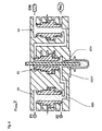
Der Aufbau des Umschaltventils U1, wie grundsätzlich auch der beiden weiteren Umschaltventile U2 und U3, wird nachfolgend anhand von
Die obere Stirnseite 4 des Kolbens 2 mündet in einen ersten Ventilraum 6 der ebenfalls im Gehäuse 1 ausgebildet ist und über eine Druckleitung 8' als Eingang mit einer externen Druckquelle 8 verbunden ist. Diese Druckquelle 8 ist beispielsweise auf dem ersten Druckniveau P1.The
Die untere Stirnseite 5 des Kolbens 2 mündet in einen zweiten Ventilraum 7, in welchem beispielsweise zentral der Ausgangskanal 30 angeordnet ist der den Ausgang U1A des Umschaltventils U1 bildet.The
Der Ventilraum 7 ist seitlich über eine Druckleitung 31 als zweiter Eingang U1E2 mit einer weiteren Druckquelle 32 verbunden, die beispielsweise auf dem zweiten Druckniveau P2 eingestellt ist.The
Weiter weist der Kolben 2 im seinem mittleren Bereich einen radial nach Aussen abstehenden Kolbenring 9 auf, der in einen Ringraum 10 des Gehäuses 1 mündet und diesen Ringraum 10 in zwei Steuerkammern untereilt, einer ersten oberen Steuerkammer 11 und einer zweiten unteren Steuerkammer 12.Next, the
An der Aussenseite des Kolbens 2 resp. der Innenwand der entsprechenden Kolbenöffnung des Gehäuses 1 sind mehrere Dichtungsringe oder Dichtungspackungen (in der Figur der Übersichtlichkeit halber nicht dargestellt) angeordnet, um die Ventilräume 6 resp. 7 gegeneinander resp. gegen die Steuerkammern 11 resp. 12 abzudichten.On the outside of the
Der Kolben 2 ist vorteilhaft in der Form als Ringkolben derart ausgebildet, dass der Kanal 3 einen möglichst grossen Durchmesser aufweist und dass der Querschnitt des Kanals 3 zwischen den beiden Stirnflächen 4 resp. 5 konstant ist und geradlinig, vorteilhaft koaxial zur Längsachse des Kolbens 2 verläuft.The
Weiter ist an der oberen Stirnfläche 4 und der unteren Stirnfläche 5 des Kolbens 2 jeweils eine Ventildichtung 13 angeordnet. Diese Ventildichtungen 13 weisen an ihrer Stirnseite jeweils eine Schliessfläche 14 auf, die in jeweils geschlossenem Zustand des Kolbens 2 gegen eine entsprechend ausgebildete Sitzfläche 15 am Boden des jeweiligen Ventilraumes 6 resp. 7 in dichtendem Anschlag stehen. In der dargestellten geschlossenen Position des Ventils ist der Kolben 2 an seinem unteren Anschlag, d.h. die Ventildichtung der Stirnfläche 5 steht gegen die Sitzfläche 15 am Boden des unteren Ventilraumes 7 in Anschlag und dichtet somit den Kanal 3 und damit auch den Ausgangskanal 30 gegen die untere Druckleitung 31 ab. Hingegen ist der Ausgangskanal 30 über den Kanal 3 mit dem oberen Ventilraum 6 und damit der Druckleitung 8' verbunden und weist damit das Druckniveau P1 auf.Further, a
Die Ventildichtung 13 weist nun weiter eine Wirkfläche 16 auf, d.h. eine zwischen der Innenwand der Schliessfläche 14 und der Innenwand des Kanals 3 angeordnete Fläche, die kleiner ist, als die gesamte Wirkfläche der oberen Ventildichtung 13 der Stirnseite 4 des Kolbens 2, die sich aus der Wirkfläche 16 und der Schliessfläche 14 zusammensetzt. Damit wird der Kolben 2 durch die Differenz zwischen den beiden Stirnseiten 4 resp. 5 durch die Druckkraft des im ersten Ventilraum 6 und damit auch im Kanal 3 herrschenden Druckes nach unten gedrückt und in der Schliesslage gehalten.The
Es ist für den Fachmann klar, dass diese Ruhestellung beispielsweise durch Anordnung einer in Schliessrichtung wirkenden Feder unterstützt werden kann, so dass das Ventil auch in drucklosem Zustand zuverlässig in der geschlossenen Stellung verbleibt.It is clear to those skilled in the art that this rest position, for example, by placing one in the closing direction acting spring can be supported, so that the valve reliably remains in the closed position even in a pressureless state.
Die Ventildichtung 13 ist vorteilhaft aus einem verschleissarmen, möglichst starren Material gefertigt und als separates Teil am Kolben 2 angeordnet.The
Als Material kommt beispielsweise ein hochfester und möglichst temperaturbeständiger Kunststoff in Frage, der als weiterer Vorteil eine Dämpfung bei einer raschen Schliessbewegung des Kolbens 2 aufweist und damit einerseits eine hohe Schliessgeschwindigkeit erlaubt und andererseits eine hohe Verschleissfestigkeit aufweist.As a material, for example, a high-strength and temperature-resistant as possible plastic in question, which has a further advantage of damping at a rapid closing movement of the
Alternativ kann die Ventildichtung 13 auch als integrierter Bestandteil direkt an der unteren Stirnfläche 5 des Kolbens 2 ausgebildet sein.Alternatively, the
Es ist für den Fachmann klar, dass das Gehäuse 1 entsprechend der Form und dem Aufbau des Kolbens 2 einteilig oder mehrteilig ausgeführt sein kann, lediglich der Einfachheit halber wird das Gehäuse 1 in den Figuren als einteilig dargestellt.It is clear to those skilled in the art that the
Für die Ansteuerung des Kolbens 2 sind die beiden Steuerkammern 11 und 12 mit einer Steuerdruckquelle 21 verbunden. So ist beispielsweise die obere Steuerkammer 11 direkt mit der Steuerdruckquelle 21 verbunden und die untere Steuerkammer 12 über ein Steuerventil 22 mit der Steuerdruckquelle 21 verbunden. In der geschlossenen Stellung des Ventils ist das Steuerventil 22 geschlossen und derart ausgelegt, dass in dieser geschlossenen Stellung die untere Steuerkammer 12 mit der Umgebung kommunizierend verbunden ist, d.h. entlüftet ist. Damit steht die obere Steuerkammer 11 unter Druck und die untere Steuerkammer 12 ist entlüftet, was den Kolben 2 durch den Druck in der Steuerkammer 11 über die erste Wirkfläche 23 in seiner geschlossenen Stellung hält.For the control of the
Die erste Wirkfläche 23 ist dabei geometrisch kleiner als die zweite Wirkfläche 24 des Kolbenringes 9 in der unteren Steuerkammer 12.The first
Wenn nun das Steuerventil 22 geöffnet wird, wird die untere Steuerkammer 12 ebenfalls mit der Steuerdruckquelle 21 verbunden, wodurch sich eine Differenzkraft zwischen der Steuerkammer 12 und 11 mit Wirkung nach oben einstellt. Wenn diese Differenzkraft nun die Haltekraft des Kolbens durch den Anpressdruck der Differenz der Wirkflächen der Stirnseiten 4 und 5 des Kolbens 2 überwindet, löst sich der Kolben 2 resp. die Schliessfläche 14 von der Sitzfläche 15 im unteren Ventilraum 7 und der Kolben 2 wird nach oben bewegt. Durch die geometrische Auslegung der Stirnflächen 4 und 5 des Kolbens 2 resp. der entsprechenden Wirkflächen sind nun unmittelbar nach dem Abheben der unteren Ventildichtung 13 gleich grosse Wirkflächen gebildet. Damit wird lediglich ein kleiner Kraftaufwand für eine schnelle, vollständige Öffnung des Ventils, d.h. vollständige Bewegung des Kolbens 2 in seine obere Endlage, wie in
In dieser offenen Stellung ist der Ausgangskanal 30 über den unteren Ventilraum 7 mit der Druckleitung 31 und damit der Druckquelle 32 auf dem Druckniveau P2 verbunden. Somit arbeitet das Ventil als Umschaltventil zwischen den beiden Druckniveaus P1 und P2. Durch die sehr schnellen Schaltzeiten des Ventils, d.h. der schnellen Bewegung des Kolbens 2 zwischen seinen zwei Positionen, kann in den Druckleitungen 31 rep. 8' in der Regel auf die Anordnung von Rückschlagventilen verzichtet werden. Weiter weist der Kolben 2 sehr gute Dämpfungseigenschaften auf, da er an seinen beiden Stirnseiten 4 resp. 5 über die Ventildichtungen 13 sehr gut abgefedert ist.In this open position, the
Durch die aussenliegende Anordnung der Wirkflächen 23 resp. 24 des Kolbenringes 9 und des möglichen grossen Querschnittes des Kanals 3 des Kolbens 2 kann daher die Steuerung des Kolbens 2 mit verhältnismässig kleinem Steuerdruckniveau erfolgen. Dies wiederum erlaubt den Einsatz von kleinen und damit kostengünstigen Steuerventilen 22 für die Ansteuerung von schnellschliessenden Ventilen mit Druckquellen 8 resp. 32 mit hohem Druckniveau.By the outer arrangement of the
Ein weiterer Vorteil dieser Ventilanordnung besteht darin, dass für eine zuverlässige Funktion des Umschaltventils, d.h. für das Öffnen und Schliessen des Kolbens 2, kein Arbeitsdruck seitens der externen Druckquellen 8 resp. 32 notwendig ist, d.h. das Ventil arbeitet selbst mit einem sehr kleinen Steuerdruckniveau. Da keine Druckdifferenz zwischen dem ersten Ventilraum 6 und dem zweiten Ventilraum 7 notwendig ist, kann das Ventil auch gesteuert werden, wenn die beiden Ventilräume 6 und 7 praktisch ohne Druck sind oder dasselbe Druckniveau aufweisen.Another advantage of this valve arrangement is that, for reliable operation of the switching valve, i. for the opening and closing of the
Die erfindungsgemässe Ventileinrichtung nach
Das zweite Umschaltventil U2 ist unmittelbar im Bereich des Blaszylinders 100 angeordnet, wobei der Ausgang U2A direkt in das Blasvolumen des Blaszylinders 100 mündet. Dabei ist der Ausgang U2A vorteilhaft im Bereich des Ventilraumes des ersten Einganges U2E1 angeordnet, der mit dem Ausgang U1A des ersten Umschaltventils U1 verbunden ist. Die für den Herstellungsprozess des Hohlkörpers notwendige Reckstange 102 ist koaxial zum Kolben 2 des Umschaltventils U2 geführt. Der zweite Eingang U2E2 dient als Entlüftungsauslass und ist mit dem Ausgang U3A des dritten Umschaltventils U3 verbunden.The second switching valve U2 is arranged directly in the region of the
Der erste Eingang U3E1 des dritten Umschaltventils U3 ist mit der Umgebung EXH, beispielsweise über einen Schalldämpfer, verbunden, während der zweite Eingang U3E2 mit einem Druckrückführungssystem REC verbunden ist. In das Druckrückführungssystem REC wird die gebrauchte Druckluft auf hohem Druckniveau nach dem Blasprozess als Sparprozess rekuperiert, bevor die Restluft an die Umgebung abgegeben wird. Beim dritten Umschaltventil U3 ist der Ausgang U3A im Bereich des Ventilraums des zweiten Eingangs U3E2 angeordnet, wodurch der Sparprozess durch kurze Verbindungswege ebenfalls sehr effizient durchgeführt werden kann.The first input U3E1 of the third switching valve U3 is connected to the environment EXH, for example via a silencer, while the second input U3E2 is connected to a pressure feedback system REC. In the pressure recirculation system REC, the used compressed air is recuperated at high pressure level after the blowing process as a saving process, before the residual air is released to the environment. In the third switching valve U3, the output U3A is arranged in the region of the valve space of the second input U3E2, as a result of which the economy process can also be carried out very efficiently by means of short connection paths.
Durch diese Ventilanordnung lässt sich die in
Im dargestellten Beispiel wird mit einem Vorblasdruck P1 von 10 bar und einem Hauptblasdruck P2 von 40 bar gearbeitet. In der Phase des Vorblasens V wird der Vorblasdruck P1 nach dem Öffnen des zweiten Umschaltventils U2 erreicht und bis zum Ende der Vorblaszeit Tv gehalten. Danach wird durch Öffnen des ersten Umschaltventils U1 die Hauptblasphase mit einem Arbeitsdruck P2 von ca. 40 bar gestartet und bis zum Ende der Hauptblaszeit Th gehalten. Vor dem Ende dieser Hauptblasphase H wird das dritte Umschaltventil U3 geöffnet, um die Verbindung zu REC vorzubereiten. Am Ende der Hauptblasphase wird das zweite Umschaltventil U2 wieder geschlossen, was zu einem Druckabbau im Blaszylinder 100 über das Druckrückführungssystem REC führt. In dieser Sparphase S wird auch das erste Umschaltventil U1 vorbereitend wieder geschlossen. Nach Ablauf der Rekuperationszeit Tr wird auch das dritte Umschaltventil U3 wieder geschlossen, womit in der Entlüftungsphase E der Druck im Blaszylinder 100 und damit auch im Hohlkörper schnell auf Umgebungsdruck abfällt und dieser damit entlüftet ist. Dabei wird aber nur noch die verbliebene Restluftmenge an die Umgebung abgegeben.In the example shown, a pre-blowing pressure P1 of 10 bar and a main blowing pressure P2 of 40 bar are used. In the pre-blowing phase V, the pre-blowing pressure P1 is reached after the opening of the second switching valve U2 and held until the end of the pre-blowing time Tv. Thereafter, by opening the first changeover valve U1, the main blowing phase is started at a working pressure P2 of about 40 bar and held until the end of the main blowing time Th. Before the end of this main blowing phase H, the third switching valve U3 is opened to prepare the connection to REC. At the end of the main blowing phase, the second switching valve U2 is closed again, which leads to a pressure reduction in the
Ein grosser Vorteil bei dieser Anordnung liegt darin, dass durch die Andordnung von drei Umschalt- oder Weichenventilen U1, U2 resp. U3 alle Ventilfunktionen einfach und mit kurzen Verbindungswegen realisiert werden können, womit schädlicher Totraum durch zusätzliche Ventile oder Leitungen vermieden wird, zumal in der Regel auf den Einsatz von Rückschlagventilen verzichtet werden kann. Damit kann angesichts der hohen Druckwerte und der in der Regel hohen Produktionsvolumen vorteilhaft eine nicht unbeträchtliche Einsparung von Druckluft erzielt werden.A big advantage with this arrangement is that by the arrangement of three switching or switch valves U1, U2 resp. U3 all valve functions can be realized easily and with short connection paths, whereby harmful dead space is avoided by additional valves or lines, especially as can be dispensed with the use of check valves in the rule. Thus, in view of the high pressure values and the generally high production volume, a not inconsiderable saving in compressed air can advantageously be achieved.
Die
In der Anordnung nach
Claims (14)
- A valve device for hollow body blowing machines for blowing compressed air into a blowing volume of a pre-form, with a first pressure feed (P1) and a second pressure feed (P2), wherein the first pressure feed (P1) has a lower pressure level than the second pressure feed (P2), and with supply lines and discharge lines to the blowing volume, said lines being capable of being shut off by means of valves, wherein the valve device comprises three switch-over valves (U1, U2, U3), a first switch-over valve (U1) with two inlets (U1E1,U1E2) and an outlet (U1A), wherein the first inlet (U1E1) is connected to the first pressure feed (P1) and the second inlet (U1E2) is connected to the second pressure feed (P2) and the outlet (U1A) is connected to a first inlet (U2E1) of the second switch-over valve (U2), the outlet (U2A) whereof is connected to the blowing volume, characterised in that a second inlet (U2E2) of the second switch-over valve (U2) is connected to the outlet (U3A) of a third switch-over valve (U3), the first inlet (U3E1) whereof is connected to the exterior (EXH) and the second inlet (U3E2) whereof is connected to a pressure feedback system (REC), wherein the switch-over valves (U1, U2, U3) comprise a valve piston (2) constituted as a hollow body, the hollow space (3) whereof is connected permanently open to the outlet (30; U1A, U2A, U3A) of the respective switch-over valve (U1, U2, U3).
- The valve device according to claim 1, characterised in that the valve piston (2) of the switch-over valves (U1, U2, U3) is constituted as a cylindrical piston longitudinally displaceable in the respective valve body (1), said cylindrical piston comprising a piston ring (9) projecting radially outwards and being disposed between the two end faces (4, 5) of the piston (2), the two end faces (23, 24) of said piston ring lying in a first control chamber (11) and a second control chamber (12).
- The valve device according to claim 2, characterised in that a first active area (23) of the piston ring (9) in the first control chamber (11) is smaller than a second active area (24) of the piston ring (9) in the second control chamber (12).
- The valve device according to claim 3, characterised in that the first control chamber (11) is connected via a first control pressure line to a control pressure reservoir (21) and the second control chamber (12) is connected via a control valve (22) in a manner capable of being switched either to the exterior or to the control pressure reservoir (21).
- The valve device according to any one of claims 2 to 4, characterised in that an annular axially orientated valve seal (13) is disposed in each case at the two end faces (4, 5) of the piston (2), the front face (14) of which valve seal forms the respective closure surface of the piston (2) and, in the closed state of the piston (2), abuts against a sealing surface (15) of the respective valve space (5; 6) and that, also in the closed state, an active area (16) acting against the closing direction is formed, wherein the geometrical dimensions of the two valve seals (13) are identical.
- The valve device according to claim 5, characterised in that the valve seals (13) of the piston (2), as the closing edge, comprise a round flange with an essentially straight closing surface area (14), wherein the closing surface area (14) is preferably orientated at right angles to the closing direction of the piston (2).
- The valve device according to claim 6, characterised in that the outer face of the flange is constituted bevelled radially inwards towards the closing surface area (14).
- The valve device according to any one of claims 2 to 8, characterised in that the piston (2) and the valve seal (13) are constituted in two parts of different materials, wherein the valve seal (13) is preferably made of plastic.
- The valve device according to any one of claims 1 to 8, characterised in that the two inlets (U1E1, U1E2) of the first switch-over valve (U1) are connected directly, without a non-return valve, to the first and respectively the second pressure feed (P1, P2).
- The valve device according to any one of claims 1 to 9, characterised in that, through the piston (2) of the second switch-over valve (U2), a stretching rod (102) of the hollow body blowing machine is arranged running coaxially or approximately normal to the longitudinal axis of the piston (2) and penetrating the hollow space (3) of the piston (2).
- A method for blowing compressed air into a blowing volume of a pre-form using compressed air, which is made available at two different pressure levels (P1; P2), wherein the blowing volume is pressurised first with the first, lower pressure level (P1) and then with the second, higher pressure level (P2) controlled by means of valves and, after the completed blowing process, the pressure present in the blowing volume is discharged to the exterior controlled by means of a vent valve, wherein- the supply of compressed air of the two different pressure levels (P1, P2) is controlled by means of a first switch-over valve (U1) ;- the compressed air supply to the blowing volume and discharge after the completed blowing process from the blowing volume is controlled by means of a second switch-over valve (U2), characterised in that- the used air discharged by the second switch-over valve (U2) is fed, controlled by a third switch-over valve (U3), to the exterior (EXH) or into a pressure feedback system (REC), wherein- the valve device is switched deaerated (E) before the start of the blowing process, wherein the second switch-over valve (U2) and the third switch-over valve (U3) are connected and the third switch-over valve (U3) is connected to the exterior (EXH) and the first switch-over valve (U1) is connected to the lower pressure level (P1);- for the start of the blowing process (V), the second switch-over valve (U2) is switched connecting to the first switch-over valve (U1);- after the lapse of a pre-defined or adjusted pre-blowing time (Tv), the first switch-over valve (U1) is switched over connecting to the higher pressure level (P2);- after the lapse of a pre-defined or adjusted main blowing time (Th), the second switch-over valve (U2) is switched over connecting to the third switch-over valve (U3) (R) and thereafter the first switch-over valve (U1) is switched back connecting to the lower pressure level (P1);- after the lapse of a pre-defined or adjusted recuperation time (Tr), the third switch-over valve (U3) is switched connecting to the exterior (EXH), as a result of which the valve device is switched deaerated (E).
- The method according to claim 11, characterised in that the first pressure level (P1) is adjusted or regulated to a pressure between 4 to 20 bar.
- The method according to claim 11 or 12, characterised in that the second pressure level (P2) is adjusted or regulated to a pressure between 15 to 40 bar.
- The method according to any one of claims 11 to 13, characterised in that the recuperation time is determined dynamically by measuring the pressure in the blowing volume and by a specific pressure value being reached or exceeded.
Applications Claiming Priority (1)
| Application Number | Priority Date | Filing Date | Title |
|---|---|---|---|
| PCT/EP2007/057398 WO2009010096A1 (en) | 2007-07-17 | 2007-07-17 | Valve device for cavity blowing machines and method for injecting compressed air into a blowing volume |
Publications (2)
| Publication Number | Publication Date |
|---|---|
| EP2167303A1 EP2167303A1 (en) | 2010-03-31 |
| EP2167303B1 true EP2167303B1 (en) | 2011-01-12 |
Family
ID=39313486
Family Applications (1)
| Application Number | Title | Priority Date | Filing Date |
|---|---|---|---|
| EP07787663A Not-in-force EP2167303B1 (en) | 2007-07-17 | 2007-07-17 | Valve device for cavity blowing machines and method for injecting compressed air into a blowing volume |
Country Status (6)
| Country | Link |
|---|---|
| EP (1) | EP2167303B1 (en) |
| CN (1) | CN101743114B (en) |
| AT (1) | ATE495005T1 (en) |
| DE (1) | DE502007006277D1 (en) |
| ES (1) | ES2358368T3 (en) |
| WO (1) | WO2009010096A1 (en) |
Cited By (1)
| Publication number | Priority date | Publication date | Assignee | Title |
|---|---|---|---|---|
| EP4082751A1 (en) | 2021-04-29 | 2022-11-02 | Eugen Seitz AG | Valve unit and method for operating a valve unit |
Families Citing this family (7)
| Publication number | Priority date | Publication date | Assignee | Title |
|---|---|---|---|---|
| EP2485883A2 (en) * | 2009-10-09 | 2012-08-15 | Norgren GmbH | A valve block assembly for a blow molding system |
| DE102009059829B4 (en) * | 2009-12-21 | 2013-09-19 | Festo Ag & Co. Kg | valve means |
| DE102009059830B4 (en) * | 2009-12-21 | 2011-11-10 | Festo Ag & Co. Kg | Valve for a blow molding machine |
| IT1401108B1 (en) | 2010-07-02 | 2013-07-12 | Smi Spa | PRESSURE ADJUSTMENT DEVICE IN STYROSOFFICING MACHINES |
| CN103126216A (en) * | 2011-11-24 | 2013-06-05 | 赵富春 | Pneumatic compression molding and pressurization deformation-resistant manufacturing technology of ornaments |
| DE102012010985A1 (en) * | 2012-06-02 | 2013-12-05 | Krones Ag | Hollow body manufacturing machine |
| WO2015121285A1 (en) * | 2014-02-11 | 2015-08-20 | Norgren Ag | A valve for a blow molding machine and a method for actuating a valve for a blow molding machine |
Family Cites Families (6)
| Publication number | Priority date | Publication date | Assignee | Title |
|---|---|---|---|---|
| DE3111925A1 (en) * | 1981-03-26 | 1982-10-07 | Robert Bosch Gmbh, 7000 Stuttgart | Process and device for saving compressed air, in particular in thermoforming machines |
| DE4340291A1 (en) * | 1993-11-26 | 1995-06-01 | Krupp Corpoplast Masch | Multiple use of blown air |
| CN2320399Y (en) * | 1998-01-25 | 1999-05-26 | 张发 | Blow-moulding mould closer |
| FR2827541B1 (en) * | 2001-07-20 | 2005-07-01 | Technoplan Engineering S A | DEVICE FOR BLOWING PACKAGES |
| ATE345207T1 (en) * | 2004-07-01 | 2006-12-15 | Kautex Maschinenbau Gmbh | METHOD FOR PRODUCING HOLLOW BODIES FROM THERMOPLASTIC PLASTIC AND DEVICE FOR CARRYING OUT THE METHOD |
| CN2902678Y (en) * | 2006-04-29 | 2007-05-23 | 亿利达机器(深圳)有限公司 | Air blowing mechanism of hollow injection moulding shaping equipment |
-
2007
- 2007-07-17 WO PCT/EP2007/057398 patent/WO2009010096A1/en active Application Filing
- 2007-07-17 AT AT07787663T patent/ATE495005T1/en active
- 2007-07-17 EP EP07787663A patent/EP2167303B1/en not_active Not-in-force
- 2007-07-17 DE DE502007006277T patent/DE502007006277D1/en active Active
- 2007-07-17 ES ES07787663T patent/ES2358368T3/en active Active
- 2007-07-17 CN CN2007800538012A patent/CN101743114B/en active Active
Cited By (1)
| Publication number | Priority date | Publication date | Assignee | Title |
|---|---|---|---|---|
| EP4082751A1 (en) | 2021-04-29 | 2022-11-02 | Eugen Seitz AG | Valve unit and method for operating a valve unit |
Also Published As
| Publication number | Publication date |
|---|---|
| EP2167303A1 (en) | 2010-03-31 |
| ES2358368T3 (en) | 2011-05-10 |
| CN101743114A (en) | 2010-06-16 |
| CN101743114B (en) | 2013-11-13 |
| WO2009010096A1 (en) | 2009-01-22 |
| ATE495005T1 (en) | 2011-01-15 |
| DE502007006277D1 (en) | 2011-02-24 |
Similar Documents
| Publication | Publication Date | Title |
|---|---|---|
| EP2167303B1 (en) | Valve device for cavity blowing machines and method for injecting compressed air into a blowing volume | |
| EP2142830B1 (en) | Air-controlled valve | |
| DE10206630B4 (en) | Method and device for high-speed pressing of workpieces | |
| DE102008015776B3 (en) | Valve unit and stretch blower equipped therewith | |
| EP3024633B1 (en) | Valve assembly | |
| DE4034518A1 (en) | PRESS ARRANGEMENT AND OPERATING PROCEDURE | |
| EP3492787B1 (en) | Valve unit | |
| DE102007013096A1 (en) | Device for treating containers | |
| DE1184943B (en) | Vulcanizing press for pneumatic vehicle tires | |
| DE102009054385B4 (en) | Coupling device and stretch blower equipped therewith | |
| DE102014000814B4 (en) | valve unit | |
| EP2240310B1 (en) | Device for injecting compressed air into a blow mold | |
| DE102009059830B4 (en) | Valve for a blow molding machine | |
| DE212006000106U1 (en) | Valve device for hollow blow molding machines | |
| EP2347887B1 (en) | Valve device | |
| WO2009010097A1 (en) | Pneumatic valve | |
| WO2007041873A1 (en) | Valve device for hollow body blowing machines | |
| DE102009018768B4 (en) | Pressure medium actuated actuator with integrated quick exhaust and additional switching force impulse during venting | |
| DE102013020280B3 (en) | Apparatus for forming a workpiece, press with such a device and method for forming a workpiece | |
| EP4082751B1 (en) | Method for operating a valve unit and valve unit | |
| EP3711925B1 (en) | Blow moulding machine with dual check valve | |
| EP3727782B1 (en) | Method for producing a molded hollow body, and device for carrying out the method | |
| EP1602867A1 (en) | Venting valve for a stretch blow molding machine | |
| DE102016104139A1 (en) | Leakage-free connection for blow molding machines | |
| DE102021128341A1 (en) | Method and apparatus for forming a preform placed in a mold of a form and fill station into a container and filling the forming container with liquid fill material |
Legal Events
| Date | Code | Title | Description |
|---|---|---|---|
| PUAI | Public reference made under article 153(3) epc to a published international application that has entered the european phase |
Free format text: ORIGINAL CODE: 0009012 |
|
| 17P | Request for examination filed |
Effective date: 20091224 |
|
| AK | Designated contracting states |
Kind code of ref document: A1 Designated state(s): AT BE BG CH CY CZ DE DK EE ES FI FR GB GR HU IE IS IT LI LT LU LV MC MT NL PL PT RO SE SI SK TR |
|
| AX | Request for extension of the european patent |
Extension state: AL BA HR MK RS |
|
| GRAP | Despatch of communication of intention to grant a patent |
Free format text: ORIGINAL CODE: EPIDOSNIGR1 |
|
| DAX | Request for extension of the european patent (deleted) | ||
| GRAS | Grant fee paid |
Free format text: ORIGINAL CODE: EPIDOSNIGR3 |
|
| GRAA | (expected) grant |
Free format text: ORIGINAL CODE: 0009210 |
|
| AK | Designated contracting states |
Kind code of ref document: B1 Designated state(s): AT BE BG CH CY CZ DE DK EE ES FI FR GB GR HU IE IS IT LI LT LU LV MC MT NL PL PT RO SE SI SK TR |
|
| REG | Reference to a national code |
Ref country code: GB Ref legal event code: FG4D Free format text: NOT ENGLISH |
|
| REG | Reference to a national code |
Ref country code: CH Ref legal event code: EP |
|
| REG | Reference to a national code |
Ref country code: IE Ref legal event code: FG4D Free format text: LANGUAGE OF EP DOCUMENT: GERMAN |
|
| REF | Corresponds to: |
Ref document number: 502007006277 Country of ref document: DE Date of ref document: 20110224 Kind code of ref document: P |
|
| REG | Reference to a national code |
Ref country code: DE Ref legal event code: R096 Ref document number: 502007006277 Country of ref document: DE Effective date: 20110224 |
|
| REG | Reference to a national code |
Ref country code: CH Ref legal event code: NV Representative=s name: R. A. EGLI & CO. PATENTANWAELTE |
|
| REG | Reference to a national code |
Ref country code: ES Ref legal event code: FG2A Ref document number: 2358368 Country of ref document: ES Kind code of ref document: T3 Effective date: 20110427 |
|
| REG | Reference to a national code |
Ref country code: NL Ref legal event code: VDEP Effective date: 20110112 |
|
| LTIE | Lt: invalidation of european patent or patent extension |
Effective date: 20110112 |
|
| PG25 | Lapsed in a contracting state [announced via postgrant information from national office to epo] |
Ref country code: IS Free format text: LAPSE BECAUSE OF FAILURE TO SUBMIT A TRANSLATION OF THE DESCRIPTION OR TO PAY THE FEE WITHIN THE PRESCRIBED TIME-LIMIT Effective date: 20110512 Ref country code: GR Free format text: LAPSE BECAUSE OF FAILURE TO SUBMIT A TRANSLATION OF THE DESCRIPTION OR TO PAY THE FEE WITHIN THE PRESCRIBED TIME-LIMIT Effective date: 20110413 Ref country code: PT Free format text: LAPSE BECAUSE OF FAILURE TO SUBMIT A TRANSLATION OF THE DESCRIPTION OR TO PAY THE FEE WITHIN THE PRESCRIBED TIME-LIMIT Effective date: 20110512 Ref country code: SE Free format text: LAPSE BECAUSE OF FAILURE TO SUBMIT A TRANSLATION OF THE DESCRIPTION OR TO PAY THE FEE WITHIN THE PRESCRIBED TIME-LIMIT Effective date: 20110112 Ref country code: LV Free format text: LAPSE BECAUSE OF FAILURE TO SUBMIT A TRANSLATION OF THE DESCRIPTION OR TO PAY THE FEE WITHIN THE PRESCRIBED TIME-LIMIT Effective date: 20110112 Ref country code: LT Free format text: LAPSE BECAUSE OF FAILURE TO SUBMIT A TRANSLATION OF THE DESCRIPTION OR TO PAY THE FEE WITHIN THE PRESCRIBED TIME-LIMIT Effective date: 20110112 |
|
| REG | Reference to a national code |
Ref country code: IE Ref legal event code: FD4D |
|
| PG25 | Lapsed in a contracting state [announced via postgrant information from national office to epo] |
Ref country code: FI Free format text: LAPSE BECAUSE OF FAILURE TO SUBMIT A TRANSLATION OF THE DESCRIPTION OR TO PAY THE FEE WITHIN THE PRESCRIBED TIME-LIMIT Effective date: 20110112 Ref country code: PL Free format text: LAPSE BECAUSE OF FAILURE TO SUBMIT A TRANSLATION OF THE DESCRIPTION OR TO PAY THE FEE WITHIN THE PRESCRIBED TIME-LIMIT Effective date: 20110112 Ref country code: SI Free format text: LAPSE BECAUSE OF FAILURE TO SUBMIT A TRANSLATION OF THE DESCRIPTION OR TO PAY THE FEE WITHIN THE PRESCRIBED TIME-LIMIT Effective date: 20110112 Ref country code: BG Free format text: LAPSE BECAUSE OF FAILURE TO SUBMIT A TRANSLATION OF THE DESCRIPTION OR TO PAY THE FEE WITHIN THE PRESCRIBED TIME-LIMIT Effective date: 20110412 Ref country code: CY Free format text: LAPSE BECAUSE OF FAILURE TO SUBMIT A TRANSLATION OF THE DESCRIPTION OR TO PAY THE FEE WITHIN THE PRESCRIBED TIME-LIMIT Effective date: 20110112 Ref country code: NL Free format text: LAPSE BECAUSE OF FAILURE TO SUBMIT A TRANSLATION OF THE DESCRIPTION OR TO PAY THE FEE WITHIN THE PRESCRIBED TIME-LIMIT Effective date: 20110112 |
|
| PG25 | Lapsed in a contracting state [announced via postgrant information from national office to epo] |
Ref country code: IE Free format text: LAPSE BECAUSE OF FAILURE TO SUBMIT A TRANSLATION OF THE DESCRIPTION OR TO PAY THE FEE WITHIN THE PRESCRIBED TIME-LIMIT Effective date: 20110112 Ref country code: EE Free format text: LAPSE BECAUSE OF FAILURE TO SUBMIT A TRANSLATION OF THE DESCRIPTION OR TO PAY THE FEE WITHIN THE PRESCRIBED TIME-LIMIT Effective date: 20110112 Ref country code: DK Free format text: LAPSE BECAUSE OF FAILURE TO SUBMIT A TRANSLATION OF THE DESCRIPTION OR TO PAY THE FEE WITHIN THE PRESCRIBED TIME-LIMIT Effective date: 20110112 |
|
| PLBE | No opposition filed within time limit |
Free format text: ORIGINAL CODE: 0009261 |
|
| STAA | Information on the status of an ep patent application or granted ep patent |
Free format text: STATUS: NO OPPOSITION FILED WITHIN TIME LIMIT |
|
| PG25 | Lapsed in a contracting state [announced via postgrant information from national office to epo] |
Ref country code: RO Free format text: LAPSE BECAUSE OF FAILURE TO SUBMIT A TRANSLATION OF THE DESCRIPTION OR TO PAY THE FEE WITHIN THE PRESCRIBED TIME-LIMIT Effective date: 20110112 Ref country code: SK Free format text: LAPSE BECAUSE OF FAILURE TO SUBMIT A TRANSLATION OF THE DESCRIPTION OR TO PAY THE FEE WITHIN THE PRESCRIBED TIME-LIMIT Effective date: 20110112 |
|
| PGFP | Annual fee paid to national office [announced via postgrant information from national office to epo] |
Ref country code: CZ Payment date: 20110714 Year of fee payment: 5 Ref country code: ES Payment date: 20110726 Year of fee payment: 5 Ref country code: GB Payment date: 20110721 Year of fee payment: 5 |
|
| 26N | No opposition filed |
Effective date: 20111013 |
|
| PG25 | Lapsed in a contracting state [announced via postgrant information from national office to epo] |
Ref country code: MT Free format text: LAPSE BECAUSE OF FAILURE TO SUBMIT A TRANSLATION OF THE DESCRIPTION OR TO PAY THE FEE WITHIN THE PRESCRIBED TIME-LIMIT Effective date: 20110112 |
|
| BERE | Be: lapsed |
Owner name: EUGEN SEITZ A.G. Effective date: 20110731 |
|
| REG | Reference to a national code |
Ref country code: DE Ref legal event code: R097 Ref document number: 502007006277 Country of ref document: DE Effective date: 20111013 |
|
| PG25 | Lapsed in a contracting state [announced via postgrant information from national office to epo] |
Ref country code: MC Free format text: LAPSE BECAUSE OF NON-PAYMENT OF DUE FEES Effective date: 20110731 |
|
| PG25 | Lapsed in a contracting state [announced via postgrant information from national office to epo] |
Ref country code: BE Free format text: LAPSE BECAUSE OF NON-PAYMENT OF DUE FEES Effective date: 20110731 |
|
| GBPC | Gb: european patent ceased through non-payment of renewal fee |
Effective date: 20120717 |
|
| PG25 | Lapsed in a contracting state [announced via postgrant information from national office to epo] |
Ref country code: CZ Free format text: LAPSE BECAUSE OF NON-PAYMENT OF DUE FEES Effective date: 20120717 Ref country code: GB Free format text: LAPSE BECAUSE OF NON-PAYMENT OF DUE FEES Effective date: 20120717 |
|
| PG25 | Lapsed in a contracting state [announced via postgrant information from national office to epo] |
Ref country code: LU Free format text: LAPSE BECAUSE OF NON-PAYMENT OF DUE FEES Effective date: 20110717 |
|
| REG | Reference to a national code |
Ref country code: AT Ref legal event code: MM01 Ref document number: 495005 Country of ref document: AT Kind code of ref document: T Effective date: 20120731 |
|
| PG25 | Lapsed in a contracting state [announced via postgrant information from national office to epo] |
Ref country code: TR Free format text: LAPSE BECAUSE OF FAILURE TO SUBMIT A TRANSLATION OF THE DESCRIPTION OR TO PAY THE FEE WITHIN THE PRESCRIBED TIME-LIMIT Effective date: 20110112 |
|
| REG | Reference to a national code |
Ref country code: ES Ref legal event code: FD2A Effective date: 20131021 |
|
| PG25 | Lapsed in a contracting state [announced via postgrant information from national office to epo] |
Ref country code: ES Free format text: LAPSE BECAUSE OF NON-PAYMENT OF DUE FEES Effective date: 20120718 Ref country code: AT Free format text: LAPSE BECAUSE OF NON-PAYMENT OF DUE FEES Effective date: 20120731 Ref country code: HU Free format text: LAPSE BECAUSE OF FAILURE TO SUBMIT A TRANSLATION OF THE DESCRIPTION OR TO PAY THE FEE WITHIN THE PRESCRIBED TIME-LIMIT Effective date: 20110112 |
|
| REG | Reference to a national code |
Ref country code: FR Ref legal event code: PLFP Year of fee payment: 10 |
|
| REG | Reference to a national code |
Ref country code: FR Ref legal event code: PLFP Year of fee payment: 11 |
|
| REG | Reference to a national code |
Ref country code: CH Ref legal event code: NV Representative=s name: ISLER AND PEDRAZZINI AG, CH |
|
| REG | Reference to a national code |
Ref country code: FR Ref legal event code: PLFP Year of fee payment: 12 |
|
| PGFP | Annual fee paid to national office [announced via postgrant information from national office to epo] |
Ref country code: DE Payment date: 20200721 Year of fee payment: 14 Ref country code: FR Payment date: 20200723 Year of fee payment: 14 |
|
| PGFP | Annual fee paid to national office [announced via postgrant information from national office to epo] |
Ref country code: CH Payment date: 20200713 Year of fee payment: 14 Ref country code: IT Payment date: 20200728 Year of fee payment: 14 |
|
| REG | Reference to a national code |
Ref country code: DE Ref legal event code: R119 Ref document number: 502007006277 Country of ref document: DE |
|
| REG | Reference to a national code |
Ref country code: CH Ref legal event code: PL |
|
| PG25 | Lapsed in a contracting state [announced via postgrant information from national office to epo] |
Ref country code: LI Free format text: LAPSE BECAUSE OF NON-PAYMENT OF DUE FEES Effective date: 20210731 Ref country code: DE Free format text: LAPSE BECAUSE OF NON-PAYMENT OF DUE FEES Effective date: 20220201 Ref country code: CH Free format text: LAPSE BECAUSE OF NON-PAYMENT OF DUE FEES Effective date: 20210731 |
|
| PG25 | Lapsed in a contracting state [announced via postgrant information from national office to epo] |
Ref country code: FR Free format text: LAPSE BECAUSE OF NON-PAYMENT OF DUE FEES Effective date: 20210731 |
|
| PG25 | Lapsed in a contracting state [announced via postgrant information from national office to epo] |
Ref country code: IT Free format text: LAPSE BECAUSE OF NON-PAYMENT OF DUE FEES Effective date: 20210717 |