EP1271029A1 - System for pneumatic control - Google Patents
System for pneumatic control Download PDFInfo
- Publication number
- EP1271029A1 EP1271029A1 EP02011900A EP02011900A EP1271029A1 EP 1271029 A1 EP1271029 A1 EP 1271029A1 EP 02011900 A EP02011900 A EP 02011900A EP 02011900 A EP02011900 A EP 02011900A EP 1271029 A1 EP1271029 A1 EP 1271029A1
- Authority
- EP
- European Patent Office
- Prior art keywords
- piston
- control
- control piston
- plastic
- butt plate
- Prior art date
- Legal status (The legal status is an assumption and is not a legal conclusion. Google has not performed a legal analysis and makes no representation as to the accuracy of the status listed.)
- Granted
Links
Images


Classifications
-
- F—MECHANICAL ENGINEERING; LIGHTING; HEATING; WEAPONS; BLASTING
- F16—ENGINEERING ELEMENTS AND UNITS; GENERAL MEASURES FOR PRODUCING AND MAINTAINING EFFECTIVE FUNCTIONING OF MACHINES OR INSTALLATIONS; THERMAL INSULATION IN GENERAL
- F16K—VALVES; TAPS; COCKS; ACTUATING-FLOATS; DEVICES FOR VENTING OR AERATING
- F16K31/00—Actuating devices; Operating means; Releasing devices
- F16K31/12—Actuating devices; Operating means; Releasing devices actuated by fluid
- F16K31/122—Actuating devices; Operating means; Releasing devices actuated by fluid the fluid acting on a piston
-
- F—MECHANICAL ENGINEERING; LIGHTING; HEATING; WEAPONS; BLASTING
- F15—FLUID-PRESSURE ACTUATORS; HYDRAULICS OR PNEUMATICS IN GENERAL
- F15B—SYSTEMS ACTING BY MEANS OF FLUIDS IN GENERAL; FLUID-PRESSURE ACTUATORS, e.g. SERVOMOTORS; DETAILS OF FLUID-PRESSURE SYSTEMS, NOT OTHERWISE PROVIDED FOR
- F15B13/00—Details of servomotor systems ; Valves for servomotor systems
- F15B13/02—Fluid distribution or supply devices characterised by their adaptation to the control of servomotors
- F15B13/04—Fluid distribution or supply devices characterised by their adaptation to the control of servomotors for use with a single servomotor
- F15B13/042—Fluid distribution or supply devices characterised by their adaptation to the control of servomotors for use with a single servomotor operated by fluid pressure
- F15B13/0426—Fluid distribution or supply devices characterised by their adaptation to the control of servomotors for use with a single servomotor operated by fluid pressure with fluid-operated pilot valves, i.e. multiple stage valves
-
- B—PERFORMING OPERATIONS; TRANSPORTING
- B29—WORKING OF PLASTICS; WORKING OF SUBSTANCES IN A PLASTIC STATE IN GENERAL
- B29C—SHAPING OR JOINING OF PLASTICS; SHAPING OF MATERIAL IN A PLASTIC STATE, NOT OTHERWISE PROVIDED FOR; AFTER-TREATMENT OF THE SHAPED PRODUCTS, e.g. REPAIRING
- B29C33/00—Moulds or cores; Details thereof or accessories therefor
- B29C33/20—Opening, closing or clamping
- B29C33/26—Opening, closing or clamping by pivotal movement
-
- B—PERFORMING OPERATIONS; TRANSPORTING
- B29—WORKING OF PLASTICS; WORKING OF SUBSTANCES IN A PLASTIC STATE IN GENERAL
- B29C—SHAPING OR JOINING OF PLASTICS; SHAPING OF MATERIAL IN A PLASTIC STATE, NOT OTHERWISE PROVIDED FOR; AFTER-TREATMENT OF THE SHAPED PRODUCTS, e.g. REPAIRING
- B29C49/00—Blow-moulding, i.e. blowing a preform or parison to a desired shape within a mould; Apparatus therefor
- B29C49/42—Component parts, details or accessories; Auxiliary operations
- B29C49/4205—Handling means, e.g. transfer, loading or discharging means
- B29C49/42073—Grippers
- B29C49/42085—Grippers holding inside the neck
-
- B—PERFORMING OPERATIONS; TRANSPORTING
- B29—WORKING OF PLASTICS; WORKING OF SUBSTANCES IN A PLASTIC STATE IN GENERAL
- B29C—SHAPING OR JOINING OF PLASTICS; SHAPING OF MATERIAL IN A PLASTIC STATE, NOT OTHERWISE PROVIDED FOR; AFTER-TREATMENT OF THE SHAPED PRODUCTS, e.g. REPAIRING
- B29C49/00—Blow-moulding, i.e. blowing a preform or parison to a desired shape within a mould; Apparatus therefor
- B29C49/42—Component parts, details or accessories; Auxiliary operations
- B29C49/4289—Valve constructions or configurations, e.g. arranged to reduce blowing fluid consumption
Definitions
- the invention relates to a device for pneumatic Control, which led one in a cylinder Control piston, which is in the direction of a Piston longitudinal axis is slidably mounted and in the through the cylinder one from the control piston lockable main flow path runs as well as at the the control piston is provided with a control surface, the a control chamber of the cylinder and facing the Transmission of a control force on the control piston is trained.
- Such devices are particularly in the Production of blow molded containers used to make a coordinated with the execution of the blowing process Feed one or more blowing pressures can.
- the Preforms as well as the blown containers with the help transported different handling equipment become. Has proven particularly the use of Transport mandrels on which the preforms are attached become.
- the preforms can also be used with others Carrying facilities are handled.
- the usage of Tongs for handling preforms and the Use of expanding mandrels for mounting in a Mouth region of the preform are insertable belong also to the available constructions.
- blowing stations used different embodiments known. at Blowing stations on rotating transport wheels arranged, is a book - like Aufklappbarkeit the Mold carrier frequently encountered. But it is also possible relative to each other displaceable or otherwise guided Insert mold carrier. For fixed blowing stations, the are particularly suitable for multiple cavities for Container molding typically becomes parallel mutually arranged plates used as a mold carrier.
- the used for the blowing air supply blowing station Devices for pneumatic control are typically realized as high pressure valves in which a control piston of a control pressure positioned so is that the control piston either a flow path for closes or releases the blowing pressure.
- a control piston of a control pressure positioned so is that the control piston either a flow path for closes or releases the blowing pressure.
- a disadvantage of the known control piston is in particular, that due to the metallic formation of the Control piston an immediate contact with the wall of the surrounding cylinder must be avoided, otherwise a heavy wear would occur.
- To avoid this Kunststoffes are similar to the arrangement of piston rings Guide bands made of plastic or similar soft Used materials that used as guide elements become.
- Guide bands made of plastic or similar soft Used materials that used as guide elements become.
- For these guide bands must be appropriate Recesses introduced in the region of the piston wall which result in corresponding manufacturing costs.
- the assembly of the guide bands also leads to a corresponding cost.
- the object of the present invention is to provide a Device of the type mentioned in the introduction to such construct that the structural design is improved.
- Control piston at least partially made of a plastic is trained.
- control piston made of plastic Due to the design of the control piston made of plastic at least in the plastic-made areas metallic contact with the wall of the cylinder avoided. Separate guide belts can therefore be avoided become.
- the formation of the control piston made of plastic moreover leads to a reduced weight and thus also to a reduced inertia and to a reduced friction in a positioning of the Piston. There are therefore lower positioning forces than in a metallic realization of the control piston required.
- control piston is formed at least in two parts.
- a simple assembly of the individual components of the Control piston can be achieved in that the Butt plate over a snap connection in the area of a Piston shaft of the control piston is attached.
- a positive attachment of the butt plate will also supported by the fact that the butt plate with a web in the groove engages.
- the butt plate with be provided a groove into which a corresponding web intervenes.
- the butt plate at least partially is made of plastic.
- the butt plate at least partially formed of PETP.
- control surface larger as the cross-sectional area of the piston skirt dimensioned is.
- control piston partially made of metal are formed.
- control piston at least partially formed of PETP.
- actuating forces during Closing the valve and holding the valve in the closed position can be specified by that the control piston has a piston skirt whose Cross-sectional area substantially equal to one Cross-sectional area of a closable by the control piston and facing a cylinder interior Flow area of the main flow path dimensioned is.
- Butt plate with a bias from the control piston is held.
- a use of the device for pneumatic control For example, to control the Blas Kunststoffzu arrangement at a device for blow molding.
- a device for the transformation of Preforms (1) in container (2) is shown in FIG. 1 and in FIG. 2 shown.
- the device for forming the container (2) consists in Substantially from a blowing station (3), which with a Blow mold (4) into which a preform (1) can be used.
- the preform (1) can be injection-molded part of polyethylene terephthalate be. to Enabling insertion of the preform (1) in the Blow mold (4) and to enable removal of the finished container (2) consists of the blow mold (4) Mold halves (5, 6) and a bottom part (7) of a Lifting device (8) is positionable.
- the preform (1) can in the area of blow station (3) from a transport mandrel (9), which together with the preform (1) a plurality of treatment stations within the Device undergoes. But it is also possible, the Preform (1) for example via pliers or others Use handling agent directly in the blow mold (4).
- a connecting piston (10) arranged which supplies compressed air to the preform (1) and at the same time a seal relative to the transport mandrel (9) makes.
- a connecting piston (10) arranged which supplies compressed air to the preform (1) and at the same time a seal relative to the transport mandrel (9) makes.
- a stretching of the preform (1) takes place with the aid of a Stretching bar (11), positioned by a cylinder (12) becomes.
- a mechanical positioning of the stretch rod (11) over Curve segments to perform by Abgriffrollen are charged.
- the use of curve segments is especially useful when a plurality of Blowing stations (3) arranged on a rotating blowing wheel are.
- a use of cylinders (12) is appropriate if stationarily arranged blowing stations (3) provided are.
- Fig. 1 is the Stretching system designed such that a tandem arrangement of two cylinders (12) is provided. Of a Primary cylinder (13), the stretch rod (11) before Beginning of the actual stretching process up to the area a bottom (14) of the preform (1) driven. While the actual stretching process, the primary cylinder (13) with extended stretch rod together with a Primary cylinder (13) carrying carriage (15) of a Secondary cylinder (16) or via a cam control positioned.
- the Use secondary cylinder (16) in a cam-controlled manner that of a guide roller (17) during the Carrying out the stretching process along a curved path slides, a current stretching position is specified.
- the Guide roller (17) is from the secondary cylinder (16) against the Guideway pressed.
- the carriage (15) slides along of two guide elements (18).
- FIG. 2 To adapt to different shapes of a mouth section (21) of the preform (1) is shown in FIG. 2 the Use of separate thread inserts (22) in the area of Blow mold (4) provided.
- Fig. 2 shows in addition to the blown container (2) also Dashed lines drawn the preform (1) and schematically a developing container bladder (23).
- Fig. 3 shows the basic structure of a Blowing machine, with a heating line (24) and a rotating blowing wheel (25) is provided.
- a heating line (24) Starting from one Preform insert (26) are the preforms (1) of Transfer wheels (27, 28, 29) in the area of the heating section (24) transported.
- Radiant heater (30) and blower (31) arranged to the To temper preforms (1).
- the finished blown containers (2) become from a further transfer wheels a discharge line (32) supplied.
- thermoplastic material can be different Plastics are used. Can be used for example PET, PEN or PP.
- the expansion of the preform (1) during the orientation process done by compressed air supply.
- the Compressed air supply is in a Vorblasphase, in the gas, for example, compressed air, with a low pressure level is fed and in a subsequent Main blowing phase divided, in the gas with a higher Pressure level is supplied.
- the Vorblasphase becomes typically compressed air with a pressure in the interval of 10 bar to 25 bar and during the main blowing phase is compressed air with a pressure in the interval of 25 bar up 40 bar supplied.
- Fig. 3 From Fig. 3 is also seen that in the illustrated embodiment, the heating section (24) a plurality of circulating transport elements (33) is formed, the chain-like strung together and along guide wheels (34) are guided. Especially is thought of by the chain-like arrangement in the réellespannen essential rectangular basic contour. at the illustrated embodiment are in the area of the Transfer wheel (29) and an input wheel (35) facing Extension of the heating section (24) a single relatively large dimensioned deflection wheel (34) and in the range of two adjacent deflections two comparatively smaller dimensioned deflection wheels (36) used. in principle but also any other guides are conceivable.
- the illustrated arrangement proves to be particularly useful, since in the area of the corresponding Extension of the heating section (24) three deflection wheels (34, 36) are positioned, and in each case the smaller ones Deflection wheels (36) in the region of the transition to the linear Course of the heating section (24) and the larger deflection (34) in the immediate transfer area to the transfer wheel (29) and to the input wheel (35).
- chain-like transport elements (33) it is for example also possible to use a rotating heating wheel.
- a larger amount of preforms (1) per unit time be tempered.
- the blower (31) direct cooling air in the range of cooling air ducts (39), the associated radiant heaters (30) each opposite and Dispense the cooling air via outflow openings.
- the cooling air channels (39) can in the range of the Radiant heaters (30) opposite surfaces Provide reflectors for the heating radiation, also It is also possible to use the discharged cooling air Cooling of the radiant heater (30) to realize.
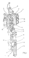
- Fig. 5 shows a vertical section through a as a High pressure valve (41) formed device for pneumatic control.
- a valve base (42) are a supply channel (43) and a discharge channel (44) arranged, which open into a cylinder interior (45), the at least partially by a cylinder wall (46) the valve base (42) is limited.
- the Supply passage (43) In the area of his Cylinder interior (45) facing extension provides the Supply passage (43) has a main flow path (47) for the to be switched high pressure with a flow area (48) ready.
- the piston shaft (50) and the piston head (51) extend substantially symmetrically along a Piston longitudinal axis (52) and together form a mushroom-like Basic structure of the control piston (49) off.
- the piston skirt (50) extends through one of Valve socket (42) held piston sleeve (53) and is relative to the piston sleeve (53) with a seal (54) sealed.
- the seal (54) may, for example, as a O-ring be formed.
- the piston shaft (50) points in the illustrated Embodiment, a cross-sectional area (55) in the essentially equal to the flow area (48) is dimensioned.
- a cross-sectional area (55) in the essentially equal to the flow area (48) is dimensioned.
- the piston skirt (50) in the area whose the piston head (51) facing away from expansion Butt plate (56) attached.
- the piston head (51) has a control surface (59) on, by a control pressure for positioning the Control piston (49) within the cylinder interior (45) can be acted upon. Adjacent to the control surface (59) extends a control room (60), in the one Feed line (61) opens for the control pressure.
- the control room (60) is partially covered by a Cylinder head (62) bounded by the valve base (42) is held. Relative to an inner wall of the Cylinder head (62) is the piston head (51) of a Sealed seal (63). To ensure a Stop damping when positioning the control piston (49) can in the piston head (51) has a damping element (64) be used.
- Fig. 5 shows the high pressure valve (41) in one closed state of the main flow path (47).
- the Piston shaft (50) is in this case with the butt plate (56) guided against the border of the main flow path (47) and seals the cylinder interior (45) from the Main flow path (47) from.
- the control surface (59) acted upon and acting on the control piston (49) Force generated larger than that of the main pressure on the Butt plate (56) acting force is dimensioned.
- control piston (49) With a lowering of the control pressure, the control piston (49) through the acting high pressure in the direction of the piston longitudinal axis (52) shifted and the high pressure can from the Main flow path (47) through the cylinder interior (47) into the region of the discharge channel (44) transgressed.
- the high pressure valve (41) is located thereby in an open state.
- control piston (49) is intended completely made of plastic.
- Guide elements (66) can then be completely eliminated.
- the piston skirt (50) and the piston head (51) together and in one piece from the to realize the same plastic. Use can be done For example, find PETP. In a partial Metallic design is particular to the use thought of aluminum.
- butt plate (56) is also preferably a plastic used. Again, here is for example, thought of the use of PETP.
- the piston head (51) provided with a diameter of about 50mm.
- One Diameter of the piston stem (50) is typically about 14mm to 20mm, especially 18mm, is also a diameter of the flow area (48) typically about 14mm to 20mm, especially 18mm. at such dimensioning usually proves for the switching of a main pressure of a maximum of 40 bar Control pressure of less than 10 bar as sufficient.
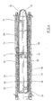
- Fig. 6 shows a partial representation of a Longitudinal section through a high pressure valve (41) with a Control piston (49), made entirely of plastic is trained.
- the control piston (49) therefore only points the seals (54, 63) on and can without use of Guide elements (66) can be realized from Fig. 6 also recognizable that to ensure a highly effective sealing also between the piston sleeve (53) and the valve base (42) or the cylinder head (62) seals (67) are arranged.
- the seals (67) can be realized for example as O-rings.
- Fig. 7 illustrates again the arrangement of Butt plate (56) in the region of the piston skirt (50) as well the arrangement of groove-shaped depressions in the control piston (49) and in the region of the piston sleeve (53) for receiving the Seals (54, 63, 67).
- the piston longitudinal axis (52) is in the in Fig. 7 illustrated embodiment in the region of the piston sleeve (53) a recess (68) for receiving the butt plate (56) in an opened state of the high pressure valve (41) arranged.
Abstract
Description
Die Erfindung betrifft eine Vorrichtung zur pneumatischen Steuerung, die einen in einem Zylinder geführten Steuerkolben aufweist, der in Richtung einer Kolbenlängsachse verschieblich gelagert ist und bei der durch den Zylinder hindurch ein vom Steuerkolben verschließbarer Hauptströmungsweg verläuft sowie bei der der Steuerkolben mit einer Steuerfläche versehen ist, die einem Steuerraum des Zylinders zugewandt ist und die zur Übertragung einer Steuerkraft auf den Steuerkolben ausgebildet ist.The invention relates to a device for pneumatic Control, which led one in a cylinder Control piston, which is in the direction of a Piston longitudinal axis is slidably mounted and in the through the cylinder one from the control piston lockable main flow path runs as well as at the the control piston is provided with a control surface, the a control chamber of the cylinder and facing the Transmission of a control force on the control piston is trained.
Derartige Vorrichtungen werden insbesondere bei der Herstellung von blasgeformten Behältern eingesetzt, um eine mit der Durchführung des Blasvorganges koordinierte Zuleitung eines oder mehrerer Blasdrücke durchführen zu können. Such devices are particularly in the Production of blow molded containers used to make a coordinated with the execution of the blowing process Feed one or more blowing pressures can.
Bei einer derartigen Behälterformung durch Blasdruckeinwirkung werden Vorformlinge aus einem thermoplastischen Material, beispielsweise Vorformlinge aus PET (Polyethylenterephthalat), innerhalb einer Blasmaschine unterschiedlichen Bearbeitungsstationen zugeführt. Typischerweise weist eine derartige Blasmaschine eine Heizeinrichtung sowie eine Blaseinrichtung auf, in deren Bereich der zuvor temperierte Vorformling durch biaxiale Orientierung zu einem Behälter expandiert wird. Die Expansion erfolgt mit Hilfe von Druckluft, die in den zu expandierenden Vorformling eingeleitet wird. Der verfahrenstechnische Ablauf bei einer derartigen Expansion des Vorformlings wird in der DE-OS 43 40 291 erläutert.In such a container molding by Blasdruckeinwirkung be preforms of a thermoplastic material, for example preforms PET (polyethylene terephthalate), within a blow molding machine supplied to different processing stations. Typically, such a blowing machine has a Heating device and a blowing device, in whose Area of previously tempered preform by biaxial Orientation is expanded to a container. The Expansion takes place with the help of compressed air in the too expanding preform is initiated. Of the procedural sequence in such an expansion of the preform is explained in DE-OS 43 40 291.
Der grundsätzliche Aufbau einer Blasstation zur Behälterformung wird in der DE-OS 42 12 583 beschrieben. Möglichkeiten zur Temperierung der Vorformlinge werden in der DE-OS 23 52 926 erläutert.The basic structure of a blowing station for Container molding is described in DE-OS 42 12 583. Possibilities for tempering the preforms are in DE-OS 23 52 926 explained.
Innerhalb der Vorrichtung zur Blasformung können die Vorformlinge sowie die geblasenen Behälter mit Hilfe unterschiedlicher Handhabungseinrichtungen transportiert werden. Bewährt hat sich insbesondere die Verwendung von Transportdornen, auf die die Vorformlinge aufgesteckt werden. Die Vorformlinge können aber auch mit anderen Trageinrichtungen gehandhabt werden. Die Verwendung von Greifzangen zur Handhabung von Vorformlingen und die Verwendung von Spreizdornen, die zur Halterung in einen Mündungsbereich des Vorformlings einführbar sind, gehören ebenfalls zu den verfügbaren Konstruktionen.Within the blow molding apparatus, the Preforms as well as the blown containers with the help transported different handling equipment become. Has proven particularly the use of Transport mandrels on which the preforms are attached become. The preforms can also be used with others Carrying facilities are handled. The usage of Tongs for handling preforms and the Use of expanding mandrels for mounting in a Mouth region of the preform are insertable belong also to the available constructions.
Die bereits erläuterte Handhabung der Vorformlinge erfolgt zum einen bei den sogenannten Zweistufenverfahren, bei denen die Vorformlinge zunächst in einem Spritzgußverfahren hergestellt, anschließend zwischengelagert und erst später hinsichtlich ihrer Temperatur konditioniert und zu einem Behälter aufgeblasen werden. Zum anderen erfolgt eine Anwendung bei den sogenannten Einstufenverfahren, bei denen die Vorformlinge unmittelbar nach ihrer spritzgußtechnischen Herstellung und einer ausreichenden Verfestigung geeignet temperiert und anschließend aufgeblasen werden.The already explained handling of the preforms takes place on the one hand in the so-called two-stage process, in which the preforms initially in an injection molding process produced, then stored temporarily and later conditioned in terms of their temperature and to a Be inflated container. On the other hand, there is a Application in the so-called one-step process, in which the preforms immediately after their injection molding production and a sufficient Solidification suitable tempered and then be inflated.
Im Hinblick auf die verwendeten Blasstationen sind unterschiedliche Ausführungsformen bekannt. Bei Blasstationen, die auf rotierenden Transporträdern angeordnet sind, ist eine buchartige Aufklappbarkeit der Formträger häufig anzutreffen. Es ist aber auch möglich, relativ zueinander verschiebliche oder andersartig geführte Formträger einzusetzen. Bei ortsfesten Blasstationen, die insbesondere dafür geeignet sind, mehrere Kavitäten zur Behälterformung aufzunehmen, werden typischerweise parallel zueinander angeordnete Platten als Formträger verwendet.With regard to the blowing stations used different embodiments known. at Blowing stations on rotating transport wheels arranged, is a book - like Aufklappbarkeit the Mold carrier frequently encountered. But it is also possible relative to each other displaceable or otherwise guided Insert mold carrier. For fixed blowing stations, the are particularly suitable for multiple cavities for Container molding typically becomes parallel mutually arranged plates used as a mold carrier.
Die für die Blasluftzuführung der Blasstation eingesetzten Vorrichtungen zur pneumatischen Steuerung sind typischerweise als Hochdruckventile realisiert, bei denen ein Steuerkolben von einem Steuerdruck derart positioniert wird, daß der Steuerkolben entweder einen Strömungsweg für den Blasdruck verschließt oder diesen freigibt. Zur Gewährleistung einer ausreichenden Abdichtung sind die bekannten Steuerkolben im Bereich einer Dichtfläche üblicherweise mit einem Elastomer vulkanisiert.The used for the blowing air supply blowing station Devices for pneumatic control are typically realized as high pressure valves in which a control piston of a control pressure positioned so is that the control piston either a flow path for closes or releases the blowing pressure. to Ensuring a sufficient seal are the known control piston in the region of a sealing surface usually vulcanized with an elastomer.
Nachteilig bei den bekannten Steuerkolben ist es insbesondere, daß aufgrund der metallischen Ausbildung des Steuerkolbens ein unmittelbarer Kontakt mit der Wandung des umgebenden Zylinders vermieden werden muß, da ansonsten ein starker Verschleiß auftreten würde. Zur Vermeidung dieses Kontaktes werden ähnlich zur Anordnung von Kolbenringen Führungsbänder aus Kunststoff oder ähnlichen weichen Materialien verwendet, die als Führungselemente eingesetzt werden. Für diese Führungsbänder müssen entsprechende Ausnehmungen im Bereich der Kolbenwandung eingebracht werden, die entsprechende Fertigungskosten zur Folge haben. Darüber hinaus führt die Montage der Führungsbänder auch zu einem entsprechenden Kostenaufwand.A disadvantage of the known control piston is in particular, that due to the metallic formation of the Control piston an immediate contact with the wall of the surrounding cylinder must be avoided, otherwise a heavy wear would occur. To avoid this Kontaktes are similar to the arrangement of piston rings Guide bands made of plastic or similar soft Used materials that used as guide elements become. For these guide bands must be appropriate Recesses introduced in the region of the piston wall which result in corresponding manufacturing costs. In addition, the assembly of the guide bands also leads to a corresponding cost.
Aufgabe der vorliegenden Erfindung ist es, eine Vorrichtung der einleitend genannten Art derart zu konstruieren, daß der konstruktive Aufbau verbessert wird.The object of the present invention is to provide a Device of the type mentioned in the introduction to such construct that the structural design is improved.
Diese Aufgabe wird erfindungsgemäß dadurch gelöst, daß der Steuerkolben mindestens bereichsweise aus einem Kunststoff ausgebildet ist.This object is achieved in that the Control piston at least partially made of a plastic is trained.
Durch die Ausbildung des Steuerkolbens aus Kunststoff wird zumindest in den aus Kunststoff gefertigten Bereichen ein metallischer Kontakt mit der Wandung des Zylinders vermieden. Separate Führungsbänder können deshalb vermieden werden. Die Ausbildung des Steuerkolbens aus Kunststoff führt darüber hinaus zu einem verringerten Gewicht und somit auch zu einer verringerten Masseträgheit sowie zu einer verminderten Reibung bei einer Positionierung des Kolbens. Es sind deshalb geringere Positionierkräfte als bei einer metallischen Realisierung des Steuerkolbens erforderlich.Due to the design of the control piston made of plastic at least in the plastic-made areas metallic contact with the wall of the cylinder avoided. Separate guide belts can therefore be avoided become. The formation of the control piston made of plastic moreover leads to a reduced weight and thus also to a reduced inertia and to a reduced friction in a positioning of the Piston. There are therefore lower positioning forces than in a metallic realization of the control piston required.
Durch diese Konstruktion ist es somit auch möglich, den maximalen Steuerdruck zu vermindern und hierdurch sowohl eine deutliche Reduzierung der Schaltzeiten als auch eine deutliche Verlängerung der Funktionsfähigkeit zu erreichen. Die Verringerung des Steuerdruckes führt zusätzlich zu einer Geräuschverringerung, so daß in gerätetechnischer Hinsicht geringer dimensionierte und somit preiswertere Schalldämpfer eingesetzt werden können.By this construction, it is thus also possible, the to reduce maximum control pressure and thereby both a significant reduction of the switching times as well as a Significant extension of functionality to achieve. The reduction of the control pressure additionally leads to a noise reduction, so that in device technology Respect smaller scale and therefore cheaper Silencer can be used.
Eine einfache Montierbarkeit wird dadurch unterstützt, daß der Steuerkolben mindestens zweiteilig ausgebildet ist.A simple mountability is supported by that the control piston is formed at least in two parts.
Insbesondere ist bei einer mehrteiligen Realisierung des Steuerkolbens daran gedacht, daß der Steuerkolben eine Schaftkappe aufweist.In particular, in a multi-part realization of Control piston thought that the control piston a Shank cap has.
Ein einfaches Zusammensetzen der einzelnen Bauteile des Steuerkolbens kann dadurch erreicht werden, daß die Schaftkappe über eine Schnappverbindung im Bereich eines Kolbenschaftes des Steuerkolbens befestigt ist.A simple assembly of the individual components of the Control piston can be achieved in that the Butt plate over a snap connection in the area of a Piston shaft of the control piston is attached.
Insbesondere wird eine sichere Arretierung der Schaftkappe dadurch erreicht, daß der Kolbenschaft eine Nut zur Halterung der Schaftkappe aufweist. Es ist aber auch möglich, den Kolbenschaft mit einem Außenprofil zu versehen, das in ein entsprechendes Gegenprofil der Schaftkappe eingreift.In particular, a secure locking of the butt plate achieved in that the piston skirt a groove for Holder of the butt plate has. It is also possible to connect the piston skirt with an external profile provided in a corresponding counter profile of Butt plate engages.
Eine formschlüssige Befestigung der Schaftkappe wird auch dadurch unterstützt, daß die Schaftkappe mit einem Steg in die Nut eingreift. Alternativ kann auch die Schaftkappe mit einer Nut versehen sein, in die ein korrespondierender Steg eingreift.A positive attachment of the butt plate will also supported by the fact that the butt plate with a web in the groove engages. Alternatively, the butt plate with be provided a groove into which a corresponding web intervenes.
Zur Vermeidung von aufvulkanisierten Dichtungen wird vorgeschlagen, daß die Schaftkappe mindestens bereichsweise aus Kunststoff ausgebildet ist. To avoid vulcanized seals is proposed that the butt plate at least partially is made of plastic.
Besonders günstige Materialeigenschaften können dadurch erreicht werden, daß die Schaftkappe mindestens bereichsweise aus PETP ausgebildet ist.Particularly favorable material properties can thereby be achieved that the butt plate at least partially formed of PETP.
Zur Verbesserung der Dichtigkeit wird vorgeschlagen, daß im Bereich des Kolbenschaftes mindestens eine Dichtung angeordnet ist.To improve the tightness is suggested that in Area of the piston skirt at least one seal is arranged.
Zur Unterstützung einer Verwendung von relativ kleinen Steuerdrücken ist vorgesehen, daß die Steuerfläche größer als die Querschnittfläche des Kolbenschaftes dimensioniert ist.To support a use of relatively small Control pressures is provided that the control surface larger as the cross-sectional area of the piston skirt dimensioned is.
Für eine kompakte konstruktive Realisierung erweist es sich als vorteilhaft, daß die Steuerfläche im Bereich eines der Schaftkappe abgewandt angeordneten Kolbenkopfes positioniert ist.It proves to be a compact constructional realization as advantageous that the control surface in the range of one of Butt plate facing away arranged piston head is positioned.
Zur Vermeidung von Druckverlusten trägt es ebenfalls bei, daß der Kolbenkopf mit mindestens einer Dichtung versehen ist.It also helps to prevent pressure losses in that the piston head is provided with at least one seal is.
Gemäß einer Ausführungsform der Erfindung ist daran gedacht, daß der Steuerkolben bereichsweise aus Metall ausgebildet sind.According to one embodiment of the invention is it thought that the control piston partially made of metal are formed.
Die Verwendung spezieller Führungsbänder am Steuerkolben kann vollständig dadurch vermieden werden, daß sowohl der Kolbenschaft als auch der Kolbenkopf aus Kunststoff ausgebildet sind. The use of special guide bands on the control piston can be completely avoided by both the Piston shaft and the piston head made of plastic are formed.
Besonders günstige Materialeigenschaften können dadurch erreicht werden, daß der Steuerkolben mindestens bereichsweise aus PETP ausgebildet sind.Particularly favorable material properties can thereby be achieved that the control piston at least partially formed of PETP.
Zur Unterstützung einer Erzeugung der Verstellkraft für den Steuerkolben wird vorgeschlagen, daß von der Steuerfläche mindestens bereichsweise ein Steuerraum zur Zuleitung eines Steuerdruckes begrenzt ist.To support a generation of the adjusting force for the Control piston is suggested that by the control surface at least partially a control room for the supply of a Control pressure is limited.
Insbesondere bei einer metallischen Realisierung des Steuerkolbens ist daran gedacht, daß der Steuerkolben als Anschlagdämpfung mit einem Dämpfungselement versehen ist.In particular, in a metallic realization of the Steuerkolbens is thought that the spool as Stop damping is provided with a damping element.
Im wesentlichen gleich große Betätigungskräfte beim Schließen des Ventils und beim Halten des Ventils in der geschlossenen Stellung können dadurch vorgegeben werden, daß der Steuerkolben einen Kolbenschaft aufweist, dessen Querschnittfläche im wesentlichen gleich einer Querschnittfläche einer vom Steuerkolben verschließbaren und einem Zylinderinnenraum zugewandten Durchströmungsfläche des Hauptströmungsweges dimensioniert ist.Essentially equal actuating forces during Closing the valve and holding the valve in the closed position can be specified by that the control piston has a piston skirt whose Cross-sectional area substantially equal to one Cross-sectional area of a closable by the control piston and facing a cylinder interior Flow area of the main flow path dimensioned is.
Zur Gewährleistung einer definierten Positionierung der Schaftkappe relativ zum Kolbenschaft wird vorgeschlagen, daß die Schaftkappe mit einer Vorspannung vom Steuerkolben gehaltert ist.To ensure a defined positioning of the Butt plate relative to the piston stem is proposed that the butt plate with a bias from the control piston is held.
In den Zeichnungen sind Ausführungsbeispiele der Erfindung schematisch dargestellt. Es zeigen:
- Fig. 1
- Eine perspektivische Darstellung einer Blasstation zur Herstellung von Behältern aus Vorformlingen,
- Fig. 2
- einen Längsschnitt durch eine Blasform, in der ein Vorformling gereckt und expandiert wird,
- Fig. 3
- eine Skizze zur Veranschaulichung eines grundsätzlichen Aufbaus einer Vorrichtung zur Blasformung von Behältern,
- Fig. 4
- eine modifizierte Heizstrecke mit vergrößerter Heizkapazität,
- Fig. 5
- einen schematischen Vertikalschnitt durch ein Hochdruckventil,
- Fig. 6:
- eine schematische Darstellung eines Steuerkolbens
aus Kunststoff, der im Steuerzylinder geführt ist
und - Fig. 7:
- eine Prinzipdarstellung eines zweiteiligen Steuerkolbens, der mit einem Kolbenschaft in einer Hülse geführt ist.
- Fig. 1
- A perspective view of a blowing station for the production of containers from preforms,
- Fig. 2
- a longitudinal section through a blow mold, in which a preform is stretched and expanded,
- Fig. 3
- a sketch to illustrate a basic structure of a device for blow molding containers,
- Fig. 4
- a modified heating section with increased heating capacity,
- Fig. 5
- a schematic vertical section through a high-pressure valve,
- Fig. 6:
- a schematic representation of a control piston made of plastic, which is guided in the control cylinder
and - Fig. 7:
- a schematic diagram of a two-part control piston, which is guided with a piston skirt in a sleeve.
Eine Verwendung der Vorrichtung zur pneumatischen Steuerung kann beispielsweise zur Steuerung der Blasluftzuführung bei einer Vorrichtung zur Blasformung erfolgen. Der prinzipielle Aufbau einer Vorrichtung zur Umformung von Vorformlingen (1) in Behälter (2) ist in Fig. 1 und in Fig. 2 dargestellt. A use of the device for pneumatic control For example, to control the Blasluftzuführung at a device for blow molding. Of the basic structure of a device for the transformation of Preforms (1) in container (2) is shown in FIG. 1 and in FIG. 2 shown.
Die Vorrichtung zur Formung des Behälters (2) besteht im wesentlichen aus einer Blasstation (3), die mit einer Blasform (4) versehen ist, in die ein Vorformling (1) einsetzbar ist. Der Vorformling (1) kann ein spritzgegossenes Teil aus Polyethylenterephthalat sein. Zur Ermöglichung eines Einsetzens des Vorformlings (1) in die Blasform (4) und zur Ermöglichung eines Herausnehmens des fertigen Behälters (2) besteht die Blasform (4) aus Formhälften (5, 6) und einem Bodenteil (7), das von einer Hubvorrichtung (8) positionierbar ist. Der Vorformling (1) kann im Bereich der Blasstation (3) von einem Transportdorn (9) gehalten sein, der gemeinsam mit dem Vorformling (1) eine Mehrzahl von Behandlungsstationen innerhalb der Vorrichtung durchläuft. Es ist aber auch möglich, den Vorformling (1) beispielsweise über Zangen oder andere Handhabungsmittel direkt in die Blasform (4) einzusetzen.The device for forming the container (2) consists in Substantially from a blowing station (3), which with a Blow mold (4) into which a preform (1) can be used. The preform (1) can be injection-molded part of polyethylene terephthalate be. to Enabling insertion of the preform (1) in the Blow mold (4) and to enable removal of the finished container (2) consists of the blow mold (4) Mold halves (5, 6) and a bottom part (7) of a Lifting device (8) is positionable. The preform (1) can in the area of blow station (3) from a transport mandrel (9), which together with the preform (1) a plurality of treatment stations within the Device undergoes. But it is also possible, the Preform (1) for example via pliers or others Use handling agent directly in the blow mold (4).
Zur Ermöglichung einer Druckluftzuleitung ist unterhalb des Transportdornes (9) ein Anschlußkolben (10) angeordnet, der dem Vorformling (1) Druckluft zuführt und gleichzeitig eine Abdichtung relativ zum Transportdorn (9) vornimmt. Bei einer abgewandelten Konstruktion ist es grundsätzlich aber auch denkbar, feste Druckluftzuleitungen zu verwenden.To enable a compressed air supply line is below the transport mandrel (9) a connecting piston (10) arranged which supplies compressed air to the preform (1) and at the same time a seal relative to the transport mandrel (9) makes. In a modified construction, it is basically but also conceivable to use solid compressed air supply lines.
Eine Reckung des Vorformlings (1) erfolgt mit Hilfe einer Reckstange (11), die von einem Zylinder (12) positioniert wird. Grundsätzlich ist es aber auch denkbar, eine mechanische Positionierung der Reckstange (11) über Kurvensegmente durchzuführen, die von Abgriffrollen beaufschlagt sind. Die Verwendung von Kurvensegmenten ist insbesondere dann zweckmäßig, wenn eine Mehrzahl von Blasstationen (3) auf einem rotierenden Blasrad angeordnet sind. Eine Verwendung von Zylindern (12) ist zweckmäßig, wenn ortsfest angeordnete Blasstationen (3) vorgesehen sind. A stretching of the preform (1) takes place with the aid of a Stretching bar (11), positioned by a cylinder (12) becomes. Basically, it is also conceivable, a mechanical positioning of the stretch rod (11) over Curve segments to perform by Abgriffrollen are charged. The use of curve segments is especially useful when a plurality of Blowing stations (3) arranged on a rotating blowing wheel are. A use of cylinders (12) is appropriate if stationarily arranged blowing stations (3) provided are.
Bei der in Fig. 1 dargestellten Ausführungsform ist das Recksystem derart ausgebildet, daß eine Tandem-Anordnung von zwei Zylindern (12) bereitgestellt ist. Von einem Primärzylinder (13) wird die Reckstange (11) zunächst vor Beginn des eigentlichen Reckvorganges bis in den Bereich eines Bodens (14) des Vorformlings (1) gefahren. Während des eigentlichen Reckvorganges wird der Primärzylinder (13) mit ausgefahrener Reckstange gemeinsam mit einem den Primärzylinder (13) tragenden Schlitten (15) von einem Sekundärzylinder (16) oder über eine Kurvensteuerung positioniert. Insbesondere ist daran gedacht, den Sekundärzylinder (16) derart kurvengesteuert einzusetzen, daß von einer Führungsrolle (17), die während der Durchführung des Reckvorganges an einer Kurvenbahn entlang gleitet, eine aktuelle Reckposition vorgegeben wird. Die Führungsrolle (17) wird vom Sekundärzylinder (16) gegen die Führungsbahn gedrückt. Der Schlitten (15) gleitet entlang von zwei Führungselementen (18).In the embodiment shown in Fig. 1 is the Stretching system designed such that a tandem arrangement of two cylinders (12) is provided. Of a Primary cylinder (13), the stretch rod (11) before Beginning of the actual stretching process up to the area a bottom (14) of the preform (1) driven. While the actual stretching process, the primary cylinder (13) with extended stretch rod together with a Primary cylinder (13) carrying carriage (15) of a Secondary cylinder (16) or via a cam control positioned. In particular, it is thought that the Use secondary cylinder (16) in a cam-controlled manner, that of a guide roller (17) during the Carrying out the stretching process along a curved path slides, a current stretching position is specified. The Guide roller (17) is from the secondary cylinder (16) against the Guideway pressed. The carriage (15) slides along of two guide elements (18).
Nach einem Schließen der im Bereich von Trägern (19, 20) angeordneten Formhälften (5, 6) erfolgt eine Verriegelung der Träger (19, 20) relativ zueinander mit Hilfe einer Verriegelungseinrichtung (20).After closing in the region of carriers (19, 20) arranged mold halves (5, 6) takes place a lock the carrier (19, 20) relative to each other by means of a Locking device (20).
Zur Anpassung an unterschiedliche Formen eines Mündungsabschnittes (21) des Vorformlings (1) ist gemäß Fig. 2 die Verwendung separater Gewindeeinsätze (22) im Bereich der Blasform (4) vorgesehen.To adapt to different shapes of a mouth section (21) of the preform (1) is shown in FIG. 2 the Use of separate thread inserts (22) in the area of Blow mold (4) provided.
Fig. 2 zeigt zusätzlich zum geblasenen Behälter (2) auch gestrichelt eingezeichnet den Vorformling (1) und schematisch eine sich entwickelnde Behälterblase (23).Fig. 2 shows in addition to the blown container (2) also Dashed lines drawn the preform (1) and schematically a developing container bladder (23).
Fig. 3 zeigt den grundsätzlichen Aufbau einer Blasmaschine, die mit einer Heizstrecke (24) sowie einem rotierenden Blasrad (25) versehen ist. Ausgehend von einer Vorformlingseingabe (26) werden die Vorformlinge (1) von Übergaberädern (27, 28, 29) in den Bereich der Heizstrecke (24) transportiert. Entlang der Heizstrecke (24) sind Heizstrahler (30) sowie Gebläse (31) angeordnet, um die Vorformlinge (1) zu temperieren. Nach einer ausreichenden Temperierung der Vorformlinge (1) werden diese an das Blasrad (25) übergeben, in dessen Bereich die Blasstationen (3) angeordnet sind. Die fertig geblasenen Behälter (2) werden von weiteren Übergaberädern einer Ausgabestrecke (32) zugeführt.Fig. 3 shows the basic structure of a Blowing machine, with a heating line (24) and a rotating blowing wheel (25) is provided. Starting from one Preform insert (26) are the preforms (1) of Transfer wheels (27, 28, 29) in the area of the heating section (24) transported. Along the heating line (24) are Radiant heater (30) and blower (31) arranged to the To temper preforms (1). After a sufficient Temperierung of the preforms (1) are these to the Blowing wheel (25) handed over, in the area of the blowing stations (3) are arranged. The finished blown containers (2) become from a further transfer wheels a discharge line (32) supplied.
Um einen Vorformling (1) derart in einen Behälter (2) umformen zu können, daß der Behälter (2) Materialeigenschaften aufweist, die eine lange Verwendungsfähigkeit von innerhalb des Behälters (2) abgefüllten Lebensmitteln, insbesondere von Getränken, gewährleisten, müssen spezielle Verfahrensschritte bei der Beheizung und Orientierung der Vorformlinge (1) eingehalten werden. Darüber hinaus können vorteilhafte Wirkungen durch Einhaltung spezieller Dimensionierungsvorschriften erzielt werden.To a preform (1) in such a container (2) to transform that the container (2) Has material properties that last a long time Usefulness of within the container (2) bottled foods, in particular drinks, must ensure special process steps in the Heating and orientation of the preforms (1) complied with become. In addition, beneficial effects can be achieved by Compliance with special dimensioning rules achieved become.
Als thermoplastisches Material können unterschiedliche Kunststoffe verwendet werden. Einsatzfähig sind beispielsweise PET, PEN oder PP.As thermoplastic material can be different Plastics are used. Can be used for example PET, PEN or PP.
Die Expansion des Vorformlings (1) während des Orientierungsvorganges erfolgt durch Druckluftzuführung. Die Druckluftzuführung ist in eine Vorblasphase, in der Gas, zum Beispiel Preßluft, mit einem niedrigen Druckniveau zugeführt wird und in eine sich anschließende Hauptblasphase unterteilt, in der Gas mit einem höheren Druckniveau zugeführt wird. Während der Vorblasphase wird typischerweise Druckluft mit einem Druck im Intervall von 10 bar bis 25 bar verwendet und während der Hauptblasphase wird Druckluft mit einem Druck im Intervall von 25 bar bis 40 bar zugeführt.The expansion of the preform (1) during the orientation process done by compressed air supply. The Compressed air supply is in a Vorblasphase, in the gas, for example, compressed air, with a low pressure level is fed and in a subsequent Main blowing phase divided, in the gas with a higher Pressure level is supplied. During the Vorblasphase becomes typically compressed air with a pressure in the interval of 10 bar to 25 bar and during the main blowing phase is compressed air with a pressure in the interval of 25 bar up 40 bar supplied.
Aus Fig. 3 ist ebenfalls erkennbar, daß bei der dargestellten Ausführungsform die Heizstrecke (24) aus einer Vielzahl umlaufender Transportelemente (33) ausgebildet ist, die kettenartig aneinandergereiht und entlang von Umlenkrädern (34) geführt sind. Insbesondere ist daran gedacht, durch die kettenartige Anordnung eine im wesentlichen rechteckförmige Grundkontur aufzuspannen. Bei der dargestellten Ausführungsform werden im Bereich der dem Übergaberad (29) und einem Eingaberad (35) zugewandten Ausdehnung der Heizstrecke (24) ein einzelnes relativ groß dimensioniertes Umlenkrad (34) und im Bereich von benachbarten Umlenkungen zwei vergleichsweise kleiner dimensionierte Umlenkräder (36) verwendet. Grundsätzlich sind aber auch beliebige andere Führungen denkbar.From Fig. 3 is also seen that in the illustrated embodiment, the heating section (24) a plurality of circulating transport elements (33) is formed, the chain-like strung together and along guide wheels (34) are guided. Especially is thought of by the chain-like arrangement in the aufzuspannen essential rectangular basic contour. at the illustrated embodiment are in the area of the Transfer wheel (29) and an input wheel (35) facing Extension of the heating section (24) a single relatively large dimensioned deflection wheel (34) and in the range of two adjacent deflections two comparatively smaller dimensioned deflection wheels (36) used. in principle but also any other guides are conceivable.
Zur Ermöglichung einer möglichst dichten Anordnung des Übergaberades (29) und des Eingaberades (35) relativ zueinander erweist sich die dargestellte Anordnung als besonders zweckmäßig, da im Bereich der entsprechenden Ausdehnung der Heizstrecke (24) drei Umlenkräder (34, 36) positioniert sind, und zwar jeweils die kleineren Umlenkräder (36) im Bereich der Überleitung zu den linearen Verläufen der Heizstrecke (24) und das größere Umlenkrad (34) im unmittelbaren Übergabebereich zum Übergaberad (29) und zum Eingaberad (35). Alternativ zur Verwendung von kettenartigen Transportelementen (33) ist es beispielsweise auch möglich, ein rotierendes Heizrad zu verwenden.To enable a dense arrangement of the Transfer wheel (29) and the input wheel (35) relative to each other, the illustrated arrangement proves to be particularly useful, since in the area of the corresponding Extension of the heating section (24) three deflection wheels (34, 36) are positioned, and in each case the smaller ones Deflection wheels (36) in the region of the transition to the linear Course of the heating section (24) and the larger deflection (34) in the immediate transfer area to the transfer wheel (29) and to the input wheel (35). Alternatively to using chain-like transport elements (33) it is for example also possible to use a rotating heating wheel.
Nach einem fertigen Blasen der Behälter (2) werden diese von einem Entnahmerad (37) aus dem Bereich der Blasstationen (3) herausgeführt und über das Übergaberad (28) und ein Ausgaberad (38) zur Ausgabestrecke (32) transportiert.After a finished blowing of the container (2) they are from a removal wheel (37) from the field of Blowing stations (3) led out and over the transfer wheel (28) and an output wheel (38) to the output path (32) transported.
In der in Fig. 4 dargestellten modifizierten Heizstrecke (24) können durch die größere Anzahl von Heizstrahlern (30) eine größere Menge von Vorformlingen (1) je Zeiteinheit temperiert werden. Die Gebläse (31) leiten hier Kühlluft in den Bereich von Kühlluftkanälen (39) ein, die den zugeordneten Heizstrahlern (30) jeweils gegenüberliegen und über Ausströmöffnungen die Kühlluft abgeben. Durch die Anordnung der Ausströmrichtungen wird eine Strömungsrichtung für die Kühlluft im wesentlichen quer zu einer Transportrichtung der Vorformlinge (1) realisiert. Die Kühlluftkanäle (39) können im Bereich von den Heizstrahlern (30) gegenüberliegenden Oberflächen Reflektoren für die Heizstrahlung bereitstellen, ebenfalls ist es möglich, über die abgegebene Kühlluft auch eine Kühlung der Heizstrahler (30) zu realisieren.In the modified heating section shown in Fig. 4 (24) may be affected by the larger number of radiant heaters (30) a larger amount of preforms (1) per unit time be tempered. The blower (31) direct cooling air in the range of cooling air ducts (39), the associated radiant heaters (30) each opposite and Dispense the cooling air via outflow openings. By the Arrangement of Ausströmrichtungen is a Flow direction for the cooling air substantially transverse to a transport direction of the preforms (1) realized. The cooling air channels (39) can in the range of the Radiant heaters (30) opposite surfaces Provide reflectors for the heating radiation, also It is also possible to use the discharged cooling air Cooling of the radiant heater (30) to realize.
Fig. 5 zeigt einen Vertikalschnitt durch eine als ein Hochdruckventil (41) ausgebildete Vorrichtung zur pneumatischen Steuerung. In einem Ventilsockel (42) sind ein Zuleitungskanal (43) sowie ein Ableitungskanal (44) angeordnet, die in einen Zylinderinnenraum (45) einmünden, der zumindest bereichsweise von einer Zylinderwandung (46) des Ventilsockels (42) begrenzt ist. Im Bereich seiner dem Zylinderinnenraum (45) zugewandten Ausdehnung stellt der Zuleitungskanal (43) einen Hauptströmungsweg (47) für den zu schaltenden Hochdruck mit einer Durchströmungsfläche (48) bereit.Fig. 5 shows a vertical section through a as a High pressure valve (41) formed device for pneumatic control. In a valve base (42) are a supply channel (43) and a discharge channel (44) arranged, which open into a cylinder interior (45), the at least partially by a cylinder wall (46) the valve base (42) is limited. In the area of his Cylinder interior (45) facing extension provides the Supply passage (43) has a main flow path (47) for the to be switched high pressure with a flow area (48) ready.
Innerhalb des Zylinderinnenraumes (45) ist ein Steuerkolben (49) geführt, der im wesentlichen aus einem Kolbenschaft (50) und einem Kolbenkopf (51) ausgebildet ist. Der Kolbenschaft (50) und der Kolbenkopf (51) erstrecken sich im wesentlichen symmetrisch entlang einer Kolbenlängsachse (52) und bilden gemeinsam eine pilzartige Grundstruktur des Steuerkolbens (49) aus.Within the cylinder interior (45) is a Control piston (49) guided, consisting essentially of a Piston shaft (50) and a piston head (51) is formed is. The piston shaft (50) and the piston head (51) extend substantially symmetrically along a Piston longitudinal axis (52) and together form a mushroom-like Basic structure of the control piston (49) off.
Der Kolbenschaft (50) erstreckt sich durch eine vom Ventilsockel (42) gehalterte Kolbenhülse (53) hindurch und ist relativ zur Kolbenhülse (53) mit einer Dichtung (54) abgedichtet. Die Dichtung (54) kann beispielsweise als ein O-Ring ausgebildet sein.The piston skirt (50) extends through one of Valve socket (42) held piston sleeve (53) and is relative to the piston sleeve (53) with a seal (54) sealed. The seal (54) may, for example, as a O-ring be formed.
Der Kolbenschaft (50) weist bei der dargestellten Ausführungsform eine Querschnittfläche (55) auf, die im wesentlichen gleich zur Durchströmungsfläche (48) dimensioniert ist. Bei der in Fig. 5 dargestellten Ausführungsform ist auf den Kolbenschaft (50) im Bereich dessen dem Kolbenkopf (51) abgewandten Ausdehnung eine Schaftkappe (56) aufgesetzt. Insbesondere ist daran gedacht, die Schaftkappe (56) mit einem Steg (57) in einer Nut (58) des Kolbenschaftes (50) zu haltern. In besonders einfacher Weise kann dies bei einer ausreichend elastischen Realisierung der Schaftkappe (56) in Form einer Schnappverbindung erfolgen.The piston shaft (50) points in the illustrated Embodiment, a cross-sectional area (55) in the essentially equal to the flow area (48) is dimensioned. In the illustrated in Fig. 5 Embodiment is on the piston skirt (50) in the area whose the piston head (51) facing away from expansion Butt plate (56) attached. In particular, it is intended, the butt plate (56) with a web (57) in one Groove groove (58) of the piston skirt (50). Especially this can easily be done with a sufficiently elastic Realization of the butt plate (56) in the form of a Snap connection done.
Im Bereich seiner dem Kolbenschaft (50) abgewandten Ausdehnung weist der Kolbenkopf (51) eine Steuerfläche (59) auf, die von einem Steuerdruck zur Positionierung des Steuerkolbens (49) innerhalb des Zylinderinnenraumes (45) beaufschlagbar ist. Angrenzend zur Steuerfläche (59) erstreckt sich ein Steuerraum (60), in den eine Zuführleitung (61) für den Steuerdruck einmündet.In the area of its the piston skirt (50) facing away Expansion, the piston head (51) has a control surface (59) on, by a control pressure for positioning the Control piston (49) within the cylinder interior (45) can be acted upon. Adjacent to the control surface (59) extends a control room (60), in the one Feed line (61) opens for the control pressure.
Der Steuerraum (60) wird bereichsweise von einem Zylinderkopf (62) begrenzt, der vom Ventilsockel (42) gehaltert ist. Relativ zu einer Innenwandung des Zylinderkopfes (62) ist der Kolbenkopf (51) von einer Dichtung (63) abgedichtet. Zur Gewährleistung einer Anschlagdämpfung bei einer Positionierung des Steuerkolbens (49) kann in den Kolbenkopf (51) ein Dämpfungselement (64) eingesetzt sein.The control room (60) is partially covered by a Cylinder head (62) bounded by the valve base (42) is held. Relative to an inner wall of the Cylinder head (62) is the piston head (51) of a Sealed seal (63). To ensure a Stop damping when positioning the control piston (49) can in the piston head (51) has a damping element (64) be used.
Zur Bereitstellung einer kompakten Ausführung ist es möglich, auf den Zylinderkopf (62) eine Zylinderhaube (65) oder einen Distanzbügel aufzusetzen, um den oberen Teil des Zylinderkopfes (62) vor mechanischen äußeren Belastungen zu schützen. Bei einer Konstruktion des Steuerkolbens (49) bereichsweise aus Metall werden zusätzlich zu den Dichtungen (54, 63) Führungselemente (66) aus Kunststoff oder ähnlichen weichen Materialien eingesetzt, um einen metallischen Kontakt zwischen dem Steuerkolben (49) und der in der Regel ebenfalls aus Metall ausgebildeten Zylinderwandung (46) beziehungsweise der Kolbenhülse (53) zu verhindern.To provide a compact design, it is possible, on the cylinder head (62) a cylinder hood (65) or put on a distance bracket to the upper part of the Cylinder head (62) against mechanical external loads too protect. In a construction of the control piston (49) In some areas of metal, in addition to the Seals (54, 63) Guide elements (66) made of plastic or similar soft materials used to make a metallic contact between the control piston (49) and the usually also made of metal Cylinder wall (46) or the piston sleeve (53) to prevent.
Fig. 5 zeigt das Hochdruckventil (41) in einem verschlossenen Zustand des Hauptströmungsweges (47). Der Kolbenschaft (50) ist hierbei mit der Schaftkappe (56) gegen die Umrandung des Hauptströmungsweges (47) geführt und dichtet den Zylinderinnenraum (45) gegenüber dem Hauptströmungsweg (47) ab. Im Bereich des Steuerraumes (60) liegt ein Steuerdruck an, der die Steuerfläche (59) beaufschlagt und eine auf den Steuerkolben (49) einwirkende Kraft erzeugt, die größer als die vom Hauptdruck auf die Schaftkappe (56) einwirkende Kraft dimensioniert ist. Hierdurch wird ein zuverlässiges Schließen des Hochdruckventils (41) gewährleistet. Bei einer Absenkung des Steuerdruckes wird der Steuerkolben (49) durch den einwirkenden Hochdruck in Richtung der Kolbenlängsachse (52) verschoben und der Hochdruck kann aus dem Hauptströmungsweg (47) durch den Zylinderinnenraum (47) hindurch in den Bereich des Ableitungskanals (44) übertreten. Das Hochdruckventil (41) befindet sich hierdurch in einem geöffneten Zustand.Fig. 5 shows the high pressure valve (41) in one closed state of the main flow path (47). Of the Piston shaft (50) is in this case with the butt plate (56) guided against the border of the main flow path (47) and seals the cylinder interior (45) from the Main flow path (47) from. In the area of the control room (60) is a control pressure, the control surface (59) acted upon and acting on the control piston (49) Force generated larger than that of the main pressure on the Butt plate (56) acting force is dimensioned. As a result, a reliable closing of the High pressure valve (41) guaranteed. With a lowering of the control pressure, the control piston (49) through the acting high pressure in the direction of the piston longitudinal axis (52) shifted and the high pressure can from the Main flow path (47) through the cylinder interior (47) into the region of the discharge channel (44) transgressed. The high pressure valve (41) is located thereby in an open state.
Bei einem erneuten Anheben des Steuerdruckes kehrt der Steuerkolben (49) in die Ursprungsposition zurück und dichtet den Hauptströmungsweg (47) wieder ab. Aufgrund der beim dargestellten Ausführungsbeispiel im wesentlichen gleichen Dimensionierung der Querschnittfläche (55) des Kolbenschaftes (50) und der Durchströmungsfläche (48) des Hauptströmungsweges (47) wirken auf den Steuerkolben (49) sowohl in einem geöffneten Zustand als auch in einem geschlossenen Zustand des Hochdruckventils (41) bezogen auf den Hochdruck im wesentlichen die gleichen Kräfte ein. Für ein Schließen des Ventils sind hierdurch im wesentlichen die gleichen Steuerkräfte wie für die Ventilzuhaltung erforderlich.When the control pressure is raised again, the Control piston (49) back to the original position and seals the main flow path (47) again. Due to the in the illustrated embodiment substantially same dimensioning of the cross - sectional area (55) of Piston shaft (50) and the flow area (48) of the Main flow path (47) acting on the control piston (49) both in an open state and in one closed state of the high pressure valve (41) based on the high pressure substantially the same forces. For a closing of the valve are thereby substantially the same control forces as for the valve tumbler required.
Insbesondere ist daran gedacht, den Steuerkolben (49) vollständig aus Kunststoff auszubilden. Die Führungselemente (66) können dann komplett entfallen. Darüber hinaus ist daran gedacht, den Kolbenschaft (50) und den Kolbenkopf (51) gemeinsam und einteilig aus dem gleichen Kunststoff zu realisieren. Verwendung kann dabei beispielsweise PETP finden. Bei einer teilweisen metallischen Ausführung ist insbesondere an die Verwendung von Aluminium gedacht.In particular, the control piston (49) is intended completely made of plastic. The Guide elements (66) can then be completely eliminated. In addition, it is thought, the piston skirt (50) and the piston head (51) together and in one piece from the to realize the same plastic. Use can be done For example, find PETP. In a partial Metallic design is particular to the use thought of aluminum.
Für die Realisierung der Schaftkappe (56) wird ebenfalls bevorzugt ein Kunststoff verwendet. Auch hier ist beispielsweise an die Verwendung von PETP gedacht.For the realization of the butt plate (56) is also preferably a plastic used. Again, here is for example, thought of the use of PETP.
Gemäß einer typischen Dimensionierung bei einer Anwendung für die Schaltung von Blasdrücken wird der Kolbenkopf (51) mit einem Durchmesser von etwa 50mm versehen. Ein Durchmesser des Kolbenschaftes (50) beträgt typischerweise etwa 14mm bis 20mm, insbesondere 18mm, ebenfalls beträgt ein Durchmesser der Durchströmungsfläche (48) typischerweise etwa 14mm bis 20mm, insbesondere 18mm. Bei einer derartigen Dimensionierung erweist sich in der Regel für die Schaltung eines Hauptdruckes von maximal 40 bar ein Steuerdruck von weniger als 10 bar als ausreichend.According to a typical sizing in one application for the switching of blowing pressures the piston head (51) provided with a diameter of about 50mm. One Diameter of the piston stem (50) is typically about 14mm to 20mm, especially 18mm, is also a diameter of the flow area (48) typically about 14mm to 20mm, especially 18mm. at such dimensioning usually proves for the switching of a main pressure of a maximum of 40 bar Control pressure of less than 10 bar as sufficient.
Fig. 6 zeigt eine teilweise Darstellung eines Längsschnittes durch ein Hochdruckventil (41) mit einem Steuerkolben (49), der vollständig aus Kunststoff ausgebildet ist. Der Steuerkolben (49) weist deshalb nur die Dichtungen (54, 63) auf und kann ohne Verwendung von Führungselementen (66) realisiert werden Aus Fig. 6 ist ebenfalls erkennbar, daß zur Gewährleistung einer hochwirksamen Abdichtung auch zwischen der Kolbenhülse (53) und dem Ventilsockel (42) beziehungsweise dem Zylinderkopf (62) Dichtungen (67) angeordnet sind. Die Dichtungen (67) können beispielsweise als O-Ringe realisiert sein.Fig. 6 shows a partial representation of a Longitudinal section through a high pressure valve (41) with a Control piston (49), made entirely of plastic is trained. The control piston (49) therefore only points the seals (54, 63) on and can without use of Guide elements (66) can be realized from Fig. 6 also recognizable that to ensure a highly effective sealing also between the piston sleeve (53) and the valve base (42) or the cylinder head (62) seals (67) are arranged. The seals (67) can be realized for example as O-rings.
Fig. 7 veranschaulicht nochmals die Anordnung der Schaftkappe (56) im Bereich des Kolbenschaftes (50) sowie die Anordnung von nutförmigen Vertiefungen im Steuerkolben (49) und im Bereich der Kolbenhülse (53) zur Aufnahme der Dichtungen (54, 63, 67). Zur Ermöglichung einer geringen Dimensionierung des Zylinderinnenraumes (45) in Richtung der Kolbenlängsachse (52) ist bei der in Fig. 7 dargestellten Ausführungsform im Bereich der Kolbenhülse (53) eine Vertiefung (68) zur Aufnahme der Schaftkappe (56) in einem geöffneten Zustand des Hochdruckventils (41) angeordnet.Fig. 7 illustrates again the arrangement of Butt plate (56) in the region of the piston skirt (50) as well the arrangement of groove-shaped depressions in the control piston (49) and in the region of the piston sleeve (53) for receiving the Seals (54, 63, 67). To enable a small Dimensioning of the cylinder interior (45) in the direction the piston longitudinal axis (52) is in the in Fig. 7 illustrated embodiment in the region of the piston sleeve (53) a recess (68) for receiving the butt plate (56) in an opened state of the high pressure valve (41) arranged.
Claims (22)
Applications Claiming Priority (2)
| Application Number | Priority Date | Filing Date | Title |
|---|---|---|---|
| DE10131557 | 2001-06-29 | ||
| DE10131557A DE10131557A1 (en) | 2001-06-29 | 2001-06-29 | Pneumatic control device |
Publications (2)
| Publication Number | Publication Date |
|---|---|
| EP1271029A1 true EP1271029A1 (en) | 2003-01-02 |
| EP1271029B1 EP1271029B1 (en) | 2006-08-23 |
Family
ID=7690022
Family Applications (1)
| Application Number | Title | Priority Date | Filing Date |
|---|---|---|---|
| EP02011900A Expired - Lifetime EP1271029B1 (en) | 2001-06-29 | 2002-05-29 | System with blowing stations for blow-moulding containers |
Country Status (4)
| Country | Link |
|---|---|
| US (1) | US7651066B2 (en) |
| EP (1) | EP1271029B1 (en) |
| AT (1) | ATE337507T1 (en) |
| DE (2) | DE10131557A1 (en) |
Cited By (8)
| Publication number | Priority date | Publication date | Assignee | Title |
|---|---|---|---|---|
| EP2078890A1 (en) | 2008-01-11 | 2009-07-15 | Festo AG & Co. KG | Valve unit |
| DE102008015776B3 (en) * | 2008-03-26 | 2009-07-23 | Festo Ag & Co. Kg | Valve unit and stretch blower equipped therewith |
| EP2460639A2 (en) | 2010-12-01 | 2012-06-06 | Krones AG | Device for blow moulding containers |
| EP2474763A1 (en) | 2011-01-10 | 2012-07-11 | Krones AG | Blow valve for expanding plastic containers |
| US8740597B2 (en) | 2011-03-04 | 2014-06-03 | Krones Ag | Blow moulding machine with a sterile chamber and sterile blowing air feed |
| US9004904B2 (en) | 2011-05-11 | 2015-04-14 | Krones Ag | Apparatus for moulding plastic preforms |
| DE102013111950A1 (en) * | 2013-10-30 | 2015-04-30 | Krones Ag | Forming device for forming plastic preforms into plastic containers |
| US9616609B2 (en) | 2011-03-04 | 2017-04-11 | Krones Ag | Sterile blow moulding machine with non-sterile media supply |
Families Citing this family (5)
| Publication number | Priority date | Publication date | Assignee | Title |
|---|---|---|---|---|
| DE10145579A1 (en) * | 2001-09-15 | 2003-07-03 | Sig Corpoplast Gmbh & Co Kg | Device for blow molding containers |
| US9353771B2 (en) | 2009-12-18 | 2016-05-31 | Norgren Gmbh | Multiple-stage valve system |
| DE102009059830B4 (en) | 2009-12-21 | 2011-11-10 | Festo Ag & Co. Kg | Valve for a blow molding machine |
| CN104583655A (en) * | 2012-07-09 | 2015-04-29 | 诺格伦公司 | Electromagnet assisted pressure-actuated valve |
| DE102013111025A1 (en) | 2013-10-04 | 2015-04-09 | Krones Ag | Valve device for the controlled introduction of a blowing medium |
Citations (4)
| Publication number | Priority date | Publication date | Assignee | Title |
|---|---|---|---|---|
| US3155367A (en) * | 1962-01-11 | 1964-11-03 | Vernay Laboratories | Valve plunger |
| US4267861A (en) * | 1979-11-05 | 1981-05-19 | Rk Industries | Plural modular fluid transfer valves |
| US4644969A (en) * | 1984-08-20 | 1987-02-24 | Oki Electric Industry Co., Ltd. | Water control valve with pneumatic actuator |
| DE19956575A1 (en) * | 1999-11-24 | 2001-05-31 | Berghof Laborprodukte Gmbh | High-pressure valve for control of aggressive media comprises a membrane which separate the media in two housing sections, and is supported by the plunger face during valve opening and closure |
Family Cites Families (9)
| Publication number | Priority date | Publication date | Assignee | Title |
|---|---|---|---|---|
| DE2352926A1 (en) | 1973-10-22 | 1975-04-24 | Heidenreich & Harbeck Gmbh | METHOD AND DEVICE FOR HEATING A WORKPIECE MADE OF PLASTIC |
| DE2613658A1 (en) * | 1976-03-31 | 1977-10-13 | Buerkert Gmbh | Sintered PTFE valve seal for corrosive fluids - has a porous core elastic enough to give a gas-tight seal |
| US4270727A (en) * | 1978-11-13 | 1981-06-02 | Torr Vacuum Products, Inc. | Spring loaded plug valve |
| DE3130129C2 (en) * | 1981-07-30 | 1985-12-05 | Krupp Corpoplast Maschinenbau GmbH, 2000 Hamburg | Blow molding machine for blow molding hollow bodies |
| US4526341A (en) * | 1983-06-15 | 1985-07-02 | Kerotest Manufacturing Corp. | Pneumatic shut-off valve |
| US4872638A (en) * | 1988-01-29 | 1989-10-10 | Semitool, Inc. | Slow acting fluid valve |
| DE4212583A1 (en) | 1992-04-15 | 1993-10-21 | Krupp Corpoplast Masch | Blow molding device |
| DE4340291A1 (en) | 1993-11-26 | 1995-06-01 | Krupp Corpoplast Masch | Multiple use of blown air |
| US6000416A (en) * | 1997-06-04 | 1999-12-14 | Furon Company | Compact valve with rolling diaphragm poppet |
-
2001
- 2001-06-29 DE DE10131557A patent/DE10131557A1/en not_active Ceased
-
2002
- 2002-05-29 AT AT02011900T patent/ATE337507T1/en active
- 2002-05-29 EP EP02011900A patent/EP1271029B1/en not_active Expired - Lifetime
- 2002-05-29 DE DE50207904T patent/DE50207904D1/en not_active Expired - Lifetime
- 2002-06-28 US US10/183,424 patent/US7651066B2/en not_active Expired - Lifetime
Patent Citations (4)
| Publication number | Priority date | Publication date | Assignee | Title |
|---|---|---|---|---|
| US3155367A (en) * | 1962-01-11 | 1964-11-03 | Vernay Laboratories | Valve plunger |
| US4267861A (en) * | 1979-11-05 | 1981-05-19 | Rk Industries | Plural modular fluid transfer valves |
| US4644969A (en) * | 1984-08-20 | 1987-02-24 | Oki Electric Industry Co., Ltd. | Water control valve with pneumatic actuator |
| DE19956575A1 (en) * | 1999-11-24 | 2001-05-31 | Berghof Laborprodukte Gmbh | High-pressure valve for control of aggressive media comprises a membrane which separate the media in two housing sections, and is supported by the plunger face during valve opening and closure |
Cited By (16)
| Publication number | Priority date | Publication date | Assignee | Title |
|---|---|---|---|---|
| EP2078890A1 (en) | 2008-01-11 | 2009-07-15 | Festo AG & Co. KG | Valve unit |
| DE102008015776B3 (en) * | 2008-03-26 | 2009-07-23 | Festo Ag & Co. Kg | Valve unit and stretch blower equipped therewith |
| EP2105641A2 (en) | 2008-03-26 | 2009-09-30 | Festo AG & Co. KG | Valve unit and stretch blowing device equipped with one |
| EP2460639A2 (en) | 2010-12-01 | 2012-06-06 | Krones AG | Device for blow moulding containers |
| DE102010052903A1 (en) | 2010-12-01 | 2012-06-06 | Krones Aktiengesellschaft | Device for blow-molding containers |
| EP3431252A1 (en) | 2010-12-01 | 2019-01-23 | Krones AG | Device for blow moulding containers |
| EP2460639B1 (en) | 2010-12-01 | 2018-10-10 | Krones AG | Device for blow moulding containers |
| EP2460639A3 (en) * | 2010-12-01 | 2014-01-15 | Krones AG | Device for blow moulding containers |
| US8708690B2 (en) | 2011-01-10 | 2014-04-29 | Krones Ag | Apparatus for the expansion of containers |
| DE102011008173A1 (en) | 2011-01-10 | 2012-07-12 | Krones Aktiengesellschaft | Blow valve for expanding plastic containers |
| EP2474763A1 (en) | 2011-01-10 | 2012-07-11 | Krones AG | Blow valve for expanding plastic containers |
| US8740597B2 (en) | 2011-03-04 | 2014-06-03 | Krones Ag | Blow moulding machine with a sterile chamber and sterile blowing air feed |
| US9616609B2 (en) | 2011-03-04 | 2017-04-11 | Krones Ag | Sterile blow moulding machine with non-sterile media supply |
| US9004904B2 (en) | 2011-05-11 | 2015-04-14 | Krones Ag | Apparatus for moulding plastic preforms |
| DE102013111950A1 (en) * | 2013-10-30 | 2015-04-30 | Krones Ag | Forming device for forming plastic preforms into plastic containers |
| US9266276B2 (en) | 2013-10-30 | 2016-02-23 | Krones Ag | Shaping apparatus for the shaping of plastics material pre-forms into plastics material containers |
Also Published As
| Publication number | Publication date |
|---|---|
| DE50207904D1 (en) | 2006-10-05 |
| ATE337507T1 (en) | 2006-09-15 |
| EP1271029B1 (en) | 2006-08-23 |
| US20030019353A1 (en) | 2003-01-30 |
| US7651066B2 (en) | 2010-01-26 |
| DE10131557A1 (en) | 2003-01-16 |
Similar Documents
| Publication | Publication Date | Title |
|---|---|---|
| DE102005011805A1 (en) | Method and apparatus for blow molding containers | |
| DE102004045405A1 (en) | Device for blow molding containers | |
| DE102008023701A1 (en) | Device for blow molding containers | |
| EP1271029B1 (en) | System with blowing stations for blow-moulding containers | |
| DE102004044260A1 (en) | Method and apparatus for blow molding containers | |
| DE102008038781A1 (en) | Method and apparatus for blow molding containers | |
| DE112008001904B4 (en) | Apparatus for blow molding containers | |
| EP1281901B1 (en) | Pneumatic controller | |
| DE112006000800B4 (en) | Process and device for blow molding containers using a movably guided valve carrier | |
| DE10354506A1 (en) | Device for blow molding containers | |
| DE102007009026A1 (en) | Method and apparatus for blow molding containers | |
| DE102012001229A1 (en) | Method and apparatus for blow molding containers | |
| DE102014017546A1 (en) | Device for holding workpieces, machine with such a device and use of such a device | |
| EP1293329A1 (en) | Device for blow-molding containers | |
| EP2054214B1 (en) | Process and apparatus for the blow moulding of containers | |
| DE102005011804A1 (en) | Blow-molding method for containers involves introducing of sealing element loosely into mouth section of preform, in area of blowing device, and then sealing element is tightened in mouth section after introduction | |
| WO2005023520A1 (en) | Method and device for blow molding containers | |
| EP1660301A1 (en) | Method and device for blow-forming containers | |
| DE102005032403A1 (en) | Thermoplastic container blow molding process involves cooling preform mouth sections during preform heating through use of fluid cooled preform carriers | |
| EP2237941B1 (en) | Method and device for blow-molding containers | |
| DE10318556A1 (en) | Method and device for blow molding containers | |
| EP2129508B1 (en) | Method for blow moulding containers |
Legal Events
| Date | Code | Title | Description |
|---|---|---|---|
| PUAI | Public reference made under article 153(3) epc to a published international application that has entered the european phase |
Free format text: ORIGINAL CODE: 0009012 |
|
| AK | Designated contracting states |
Kind code of ref document: A1 Designated state(s): AT BE CH CY DE DK ES FI FR GB GR IE IT LI LU MC NL PT SE TR |
|
| AX | Request for extension of the european patent |
Free format text: AL;LT;LV;MK;RO;SI |
|
| AKX | Designation fees paid |
Designated state(s): AT BE CH CY DE DK ES FI FR GB GR IE IT LI LU MC NL PT SE TR |
|
| 17P | Request for examination filed |
Effective date: 20030816 |
|
| 17Q | First examination report despatched |
Effective date: 20040128 |
|
| APBN | Date of receipt of notice of appeal recorded |
Free format text: ORIGINAL CODE: EPIDOSNNOA2E |
|
| APBR | Date of receipt of statement of grounds of appeal recorded |
Free format text: ORIGINAL CODE: EPIDOSNNOA3E |
|
| APBV | Interlocutory revision of appeal recorded |
Free format text: ORIGINAL CODE: EPIDOSNIRAPE |
|
| GRAP | Despatch of communication of intention to grant a patent |
Free format text: ORIGINAL CODE: EPIDOSNIGR1 |
|
| RTI1 | Title (correction) |
Free format text: SYSTEM WITH BLOWING STATIONS FOR BLOW-MOULDING CONTAINERS |
|
| GRAS | Grant fee paid |
Free format text: ORIGINAL CODE: EPIDOSNIGR3 |
|
| GRAA | (expected) grant |
Free format text: ORIGINAL CODE: 0009210 |
|
| AK | Designated contracting states |
Kind code of ref document: B1 Designated state(s): AT BE CH CY DE DK ES FI FR GB GR IE IT LI LU MC NL PT SE TR |
|
| PG25 | Lapsed in a contracting state [announced via postgrant information from national office to epo] |
Ref country code: FI Free format text: LAPSE BECAUSE OF FAILURE TO SUBMIT A TRANSLATION OF THE DESCRIPTION OR TO PAY THE FEE WITHIN THE PRESCRIBED TIME-LIMIT Effective date: 20060823 Ref country code: IE Free format text: LAPSE BECAUSE OF FAILURE TO SUBMIT A TRANSLATION OF THE DESCRIPTION OR TO PAY THE FEE WITHIN THE PRESCRIBED TIME-LIMIT Effective date: 20060823 Ref country code: IT Free format text: LAPSE BECAUSE OF FAILURE TO SUBMIT A TRANSLATION OF THE DESCRIPTION OR TO PAY THE FEE WITHIN THE PRESCRIBED TIME-LIMIT;WARNING: LAPSES OF ITALIAN PATENTS WITH EFFECTIVE DATE BEFORE 2007 MAY HAVE OCCURRED AT ANY TIME BEFORE 2007. THE CORRECT EFFECTIVE DATE MAY BE DIFFERENT FROM THE ONE RECORDED. Effective date: 20060823 Ref country code: NL Free format text: LAPSE BECAUSE OF FAILURE TO SUBMIT A TRANSLATION OF THE DESCRIPTION OR TO PAY THE FEE WITHIN THE PRESCRIBED TIME-LIMIT Effective date: 20060823 |
|
| REG | Reference to a national code |
Ref country code: GB Ref legal event code: FG4D Free format text: NOT ENGLISH |
|
| REG | Reference to a national code |
Ref country code: CH Ref legal event code: EP |
|
| REG | Reference to a national code |
Ref country code: IE Ref legal event code: FG4D Free format text: LANGUAGE OF EP DOCUMENT: GERMAN |
|
| REF | Corresponds to: |
Ref document number: 50207904 Country of ref document: DE Date of ref document: 20061005 Kind code of ref document: P |
|
| PG25 | Lapsed in a contracting state [announced via postgrant information from national office to epo] |
Ref country code: DK Free format text: LAPSE BECAUSE OF FAILURE TO SUBMIT A TRANSLATION OF THE DESCRIPTION OR TO PAY THE FEE WITHIN THE PRESCRIBED TIME-LIMIT Effective date: 20061123 Ref country code: SE Free format text: LAPSE BECAUSE OF FAILURE TO SUBMIT A TRANSLATION OF THE DESCRIPTION OR TO PAY THE FEE WITHIN THE PRESCRIBED TIME-LIMIT Effective date: 20061123 |
|
| PG25 | Lapsed in a contracting state [announced via postgrant information from national office to epo] |
Ref country code: ES Free format text: LAPSE BECAUSE OF FAILURE TO SUBMIT A TRANSLATION OF THE DESCRIPTION OR TO PAY THE FEE WITHIN THE PRESCRIBED TIME-LIMIT Effective date: 20061204 |
|
| REG | Reference to a national code |
Ref country code: CH Ref legal event code: NV Representative=s name: PA ALDO ROEMPLER |
|
| PG25 | Lapsed in a contracting state [announced via postgrant information from national office to epo] |
Ref country code: PT Free format text: LAPSE BECAUSE OF FAILURE TO SUBMIT A TRANSLATION OF THE DESCRIPTION OR TO PAY THE FEE WITHIN THE PRESCRIBED TIME-LIMIT Effective date: 20070124 |
|
| NLV1 | Nl: lapsed or annulled due to failure to fulfill the requirements of art. 29p and 29m of the patents act | ||
| REG | Reference to a national code |
Ref country code: IE Ref legal event code: FD4D |
|
| ET | Fr: translation filed | ||
| PLBI | Opposition filed |
Free format text: ORIGINAL CODE: 0009260 |
|
| PLAX | Notice of opposition and request to file observation + time limit sent |
Free format text: ORIGINAL CODE: EPIDOSNOBS2 |
|
| 26 | Opposition filed |
Opponent name: KRONES AKTIENGESELLSCHAFT Effective date: 20070523 |
|
| PLBB | Reply of patent proprietor to notice(s) of opposition received |
Free format text: ORIGINAL CODE: EPIDOSNOBS3 |
|
| BERE | Be: lapsed |
Owner name: SIG CORPOPLAST G.M.B.H. & CO. KG Effective date: 20070531 |
|
| REG | Reference to a national code |
Ref country code: GB Ref legal event code: 732E |
|
| PG25 | Lapsed in a contracting state [announced via postgrant information from national office to epo] |
Ref country code: MC Free format text: LAPSE BECAUSE OF NON-PAYMENT OF DUE FEES Effective date: 20070531 |
|
| PG25 | Lapsed in a contracting state [announced via postgrant information from national office to epo] |
Ref country code: BE Free format text: LAPSE BECAUSE OF NON-PAYMENT OF DUE FEES Effective date: 20070531 |
|
| PG25 | Lapsed in a contracting state [announced via postgrant information from national office to epo] |
Ref country code: GR Free format text: LAPSE BECAUSE OF FAILURE TO SUBMIT A TRANSLATION OF THE DESCRIPTION OR TO PAY THE FEE WITHIN THE PRESCRIBED TIME-LIMIT Effective date: 20061124 |
|
| PLBP | Opposition withdrawn |
Free format text: ORIGINAL CODE: 0009264 |
|
| PLBD | Termination of opposition procedure: decision despatched |
Free format text: ORIGINAL CODE: EPIDOSNOPC1 |
|
| REG | Reference to a national code |
Ref country code: CH Ref legal event code: PCAR Free format text: ALDO ROEMPLER PATENTANWALT;BRENDENWEG 11 POSTFACH 154;9424 RHEINECK (CH) |
|
| PLBM | Termination of opposition procedure: date of legal effect published |
Free format text: ORIGINAL CODE: 0009276 |
|
| STAA | Information on the status of an ep patent application or granted ep patent |
Free format text: STATUS: OPPOSITION PROCEDURE CLOSED |
|
| 27C | Opposition proceedings terminated |
Effective date: 20080828 |
|
| REG | Reference to a national code |
Ref country code: GB Ref legal event code: 732E |
|
| REG | Reference to a national code |
Ref country code: FR Ref legal event code: CD Ref country code: FR Ref legal event code: TQ |
|
| REG | Reference to a national code |
Ref country code: CH Ref legal event code: PUEA Owner name: KHS CORPOPLAST GMBH & CO. KG Free format text: KHS CORPOPLAST GMBH & CO. KG#MEIENDORFER STRASSE 203#20439 HAMBURG (DE) -TRANSFER TO- KHS CORPOPLAST GMBH & CO. KG#MEIENDORFER STRASSE 203#20439 HAMBURG (DE) $ NORGREN AG#WERKSTRASSE#8362 BALTERSWIL (CH) Ref country code: CH Ref legal event code: PFA Owner name: KHS CORPOPLAST GMBH & CO. KG Free format text: SIG CORPOPLAST GMBH & CO. KG#MEIENDORFER STRASSE 203#22145 HAMBURG (DE) -TRANSFER TO- KHS CORPOPLAST GMBH & CO. KG#MEIENDORFER STRASSE 203#20439 HAMBURG (DE) |
|
| PG25 | Lapsed in a contracting state [announced via postgrant information from national office to epo] |
Ref country code: LU Free format text: LAPSE BECAUSE OF NON-PAYMENT OF DUE FEES Effective date: 20070529 Ref country code: CY Free format text: LAPSE BECAUSE OF FAILURE TO SUBMIT A TRANSLATION OF THE DESCRIPTION OR TO PAY THE FEE WITHIN THE PRESCRIBED TIME-LIMIT Effective date: 20060823 |
|
| PG25 | Lapsed in a contracting state [announced via postgrant information from national office to epo] |
Ref country code: TR Free format text: LAPSE BECAUSE OF FAILURE TO SUBMIT A TRANSLATION OF THE DESCRIPTION OR TO PAY THE FEE WITHIN THE PRESCRIBED TIME-LIMIT Effective date: 20060823 |
|
| REG | Reference to a national code |
Ref country code: DE Ref legal event code: R081 Ref document number: 50207904 Country of ref document: DE Owner name: NORGEN AG, CH Free format text: FORMER OWNER: KHS CORPOPLAST GMBH & CO. KG, NORGEN AG, , CH Effective date: 20110504 Ref country code: DE Ref legal event code: R081 Ref document number: 50207904 Country of ref document: DE Owner name: KHS CORPOPLAST GMBH, DE Free format text: FORMER OWNER: KHS CORPOPLAST GMBH & CO. KG, NORGEN AG, , CH Effective date: 20110504 Ref country code: DE Ref legal event code: R081 Ref document number: 50207904 Country of ref document: DE Owner name: NORGEN AG, CH Free format text: FORMER OWNERS: KHS CORPOPLAST GMBH & CO. KG, 22145 HAMBURG, DE; NORGEN AG, BALTERSWIL, CH Effective date: 20110504 Ref country code: DE Ref legal event code: R081 Ref document number: 50207904 Country of ref document: DE Owner name: KHS CORPOPLAST GMBH, DE Free format text: FORMER OWNERS: KHS CORPOPLAST GMBH & CO. KG, 22145 HAMBURG, DE; NORGEN AG, BALTERSWIL, CH Effective date: 20110504 |
|
| REG | Reference to a national code |
Ref country code: GB Ref legal event code: S72Z Free format text: CLAIM LODGED; PATENTS COURT ON 16 DECEMBER 2010 (HC10C04475) |
|
| REG | Reference to a national code |
Ref country code: DE Ref legal event code: R097 Ref document number: 50207904 Country of ref document: DE Ref country code: DE Ref legal event code: R040 Ref document number: 50207904 Country of ref document: DE |
|
| REG | Reference to a national code |
Ref country code: DE Ref legal event code: R040 Ref document number: 50207904 Country of ref document: DE Effective date: 20140623 |
|
| REG | Reference to a national code |
Ref country code: GB Ref legal event code: S75Z Free format text: APPLICATION TO AMEND UNDER SECTION 75 FILED ON 23 NOVEMBER 2012. BY ORDER OF THE COURT DATED 03 FEBRUARY 2014 THE PATENT AS AMENDED REMAINS PARTIALLY VALID. CLAIM 1 OF THE AMENDED PATENT WAS FOUND TO BE VALID AND CLAIM 18 WAS INDEPENDENTLY VALID. CLAIM 15 WAS NOT INDEPENDENTLY VALID. (HC10 C04475) Ref country code: GB Ref legal event code: S72Z Free format text: CLAIM 1 OF THE AMENDED PATENT WAS FOUND TO BE VALID AND CLAIM 18 WAS DEEMED INDEPENDENTLY VALID. CLAIM 15 WAS DECLARED NOT INDEPENDENTLY VALID. THE CLAIM FOR REVOCATION WAS THEREFORE DISMISSED. (COURT ACTION NO. HC10 C04475) |
|
| REG | Reference to a national code |
Ref country code: DE Ref legal event code: R082 Ref document number: 50207904 Country of ref document: DE |
|
| REG | Reference to a national code |
Ref country code: FR Ref legal event code: PLFP Year of fee payment: 15 |
|
| REG | Reference to a national code |
Ref country code: FR Ref legal event code: PLFP Year of fee payment: 16 |
|
| REG | Reference to a national code |
Ref country code: FR Ref legal event code: PLFP Year of fee payment: 17 |
|
| PGFP | Annual fee paid to national office [announced via postgrant information from national office to epo] |
Ref country code: IT Payment date: 20210527 Year of fee payment: 20 Ref country code: DE Payment date: 20210520 Year of fee payment: 20 Ref country code: FR Payment date: 20210520 Year of fee payment: 20 |
|
| PGFP | Annual fee paid to national office [announced via postgrant information from national office to epo] |
Ref country code: AT Payment date: 20210520 Year of fee payment: 20 Ref country code: CH Payment date: 20210519 Year of fee payment: 20 Ref country code: GB Payment date: 20210520 Year of fee payment: 20 |
|
| REG | Reference to a national code |
Ref country code: DE Ref legal event code: R071 Ref document number: 50207904 Country of ref document: DE |
|
| REG | Reference to a national code |
Ref country code: CH Ref legal event code: PL |
|
| REG | Reference to a national code |
Ref country code: GB Ref legal event code: PE20 Expiry date: 20220528 |
|
| REG | Reference to a national code |
Ref country code: AT Ref legal event code: MK07 Ref document number: 337507 Country of ref document: AT Kind code of ref document: T Effective date: 20220529 |
|
| PG25 | Lapsed in a contracting state [announced via postgrant information from national office to epo] |
Ref country code: GB Free format text: LAPSE BECAUSE OF EXPIRATION OF PROTECTION Effective date: 20220528 |