EP2459328B1 - Method and apparatus for setting rolling element bearings in rolling mills - Google Patents
Method and apparatus for setting rolling element bearings in rolling mills Download PDFInfo
- Publication number
- EP2459328B1 EP2459328B1 EP10742361.8A EP10742361A EP2459328B1 EP 2459328 B1 EP2459328 B1 EP 2459328B1 EP 10742361 A EP10742361 A EP 10742361A EP 2459328 B1 EP2459328 B1 EP 2459328B1
- Authority
- EP
- European Patent Office
- Prior art keywords
- axial
- center rod
- assembly
- bearing
- chock
- Prior art date
- Legal status (The legal status is an assumption and is not a legal conclusion. Google has not performed a legal analysis and makes no representation as to the accuracy of the status listed.)
- Not-in-force
Links
- 238000000034 method Methods 0.000 title claims description 36
- 238000005096 rolling process Methods 0.000 title claims description 12
- 210000003739 neck Anatomy 0.000 claims description 35
- 230000000712 assembly Effects 0.000 claims description 21
- 238000000429 assembly Methods 0.000 claims description 21
- 230000007704 transition Effects 0.000 claims description 6
- 230000004323 axial length Effects 0.000 claims description 5
- 230000008878 coupling Effects 0.000 claims description 5
- 238000010168 coupling process Methods 0.000 claims description 5
- 238000005859 coupling reaction Methods 0.000 claims description 5
- 238000012544 monitoring process Methods 0.000 claims description 2
- 230000000717 retained effect Effects 0.000 claims 2
- 230000036316 preload Effects 0.000 description 26
- 230000008569 process Effects 0.000 description 8
- 238000005452 bending Methods 0.000 description 6
- 238000011900 installation process Methods 0.000 description 4
- 230000007423 decrease Effects 0.000 description 3
- 230000000694 effects Effects 0.000 description 3
- 230000007246 mechanism Effects 0.000 description 3
- 239000002184 metal Substances 0.000 description 3
- 125000006850 spacer group Chemical group 0.000 description 3
- 238000004458 analytical method Methods 0.000 description 2
- 238000004519 manufacturing process Methods 0.000 description 2
- 230000006978 adaptation Effects 0.000 description 1
- 230000004075 alteration Effects 0.000 description 1
- 230000003466 anti-cipated effect Effects 0.000 description 1
- 238000005266 casting Methods 0.000 description 1
- 230000008859 change Effects 0.000 description 1
- 239000003795 chemical substances by application Substances 0.000 description 1
- 238000010276 construction Methods 0.000 description 1
- 230000003247 decreasing effect Effects 0.000 description 1
- 239000000428 dust Substances 0.000 description 1
- 238000005516 engineering process Methods 0.000 description 1
- 239000012530 fluid Substances 0.000 description 1
- 239000011888 foil Substances 0.000 description 1
- 238000005242 forging Methods 0.000 description 1
- 238000010438 heat treatment Methods 0.000 description 1
- 230000013011 mating Effects 0.000 description 1
- 238000012986 modification Methods 0.000 description 1
- 230000004048 modification Effects 0.000 description 1
- 230000000452 restraining effect Effects 0.000 description 1
- 230000001052 transient effect Effects 0.000 description 1
Images




Classifications
-
- B—PERFORMING OPERATIONS; TRANSPORTING
- B21—MECHANICAL METAL-WORKING WITHOUT ESSENTIALLY REMOVING MATERIAL; PUNCHING METAL
- B21B—ROLLING OF METAL
- B21B31/00—Rolling stand structures; Mounting, adjusting, or interchanging rolls, roll mountings, or stand frames
- B21B31/07—Adaptation of roll neck bearings
-
- F—MECHANICAL ENGINEERING; LIGHTING; HEATING; WEAPONS; BLASTING
- F16—ENGINEERING ELEMENTS AND UNITS; GENERAL MEASURES FOR PRODUCING AND MAINTAINING EFFECTIVE FUNCTIONING OF MACHINES OR INSTALLATIONS; THERMAL INSULATION IN GENERAL
- F16C—SHAFTS; FLEXIBLE SHAFTS; ELEMENTS OR CRANKSHAFT MECHANISMS; ROTARY BODIES OTHER THAN GEARING ELEMENTS; BEARINGS
- F16C13/00—Rolls, drums, discs, or the like; Bearings or mountings therefor
- F16C13/02—Bearings
-
- F—MECHANICAL ENGINEERING; LIGHTING; HEATING; WEAPONS; BLASTING
- F16—ENGINEERING ELEMENTS AND UNITS; GENERAL MEASURES FOR PRODUCING AND MAINTAINING EFFECTIVE FUNCTIONING OF MACHINES OR INSTALLATIONS; THERMAL INSULATION IN GENERAL
- F16C—SHAFTS; FLEXIBLE SHAFTS; ELEMENTS OR CRANKSHAFT MECHANISMS; ROTARY BODIES OTHER THAN GEARING ELEMENTS; BEARINGS
- F16C19/00—Bearings with rolling contact, for exclusively rotary movement
- F16C19/22—Bearings with rolling contact, for exclusively rotary movement with bearing rollers essentially of the same size in one or more circular rows, e.g. needle bearings
- F16C19/34—Bearings with rolling contact, for exclusively rotary movement with bearing rollers essentially of the same size in one or more circular rows, e.g. needle bearings for both radial and axial load
- F16C19/38—Bearings with rolling contact, for exclusively rotary movement with bearing rollers essentially of the same size in one or more circular rows, e.g. needle bearings for both radial and axial load with two or more rows of rollers
- F16C19/383—Bearings with rolling contact, for exclusively rotary movement with bearing rollers essentially of the same size in one or more circular rows, e.g. needle bearings for both radial and axial load with two or more rows of rollers with tapered rollers, i.e. rollers having essentially the shape of a truncated cone
- F16C19/388—Bearings with rolling contact, for exclusively rotary movement with bearing rollers essentially of the same size in one or more circular rows, e.g. needle bearings for both radial and axial load with two or more rows of rollers with tapered rollers, i.e. rollers having essentially the shape of a truncated cone with four rows, i.e. four row tapered roller bearings
-
- F—MECHANICAL ENGINEERING; LIGHTING; HEATING; WEAPONS; BLASTING
- F16—ENGINEERING ELEMENTS AND UNITS; GENERAL MEASURES FOR PRODUCING AND MAINTAINING EFFECTIVE FUNCTIONING OF MACHINES OR INSTALLATIONS; THERMAL INSULATION IN GENERAL
- F16C—SHAFTS; FLEXIBLE SHAFTS; ELEMENTS OR CRANKSHAFT MECHANISMS; ROTARY BODIES OTHER THAN GEARING ELEMENTS; BEARINGS
- F16C25/00—Bearings for exclusively rotary movement adjustable for wear or play
- F16C25/06—Ball or roller bearings
-
- F—MECHANICAL ENGINEERING; LIGHTING; HEATING; WEAPONS; BLASTING
- F16—ENGINEERING ELEMENTS AND UNITS; GENERAL MEASURES FOR PRODUCING AND MAINTAINING EFFECTIVE FUNCTIONING OF MACHINES OR INSTALLATIONS; THERMAL INSULATION IN GENERAL
- F16C—SHAFTS; FLEXIBLE SHAFTS; ELEMENTS OR CRANKSHAFT MECHANISMS; ROTARY BODIES OTHER THAN GEARING ELEMENTS; BEARINGS
- F16C2229/00—Setting preload
-
- F—MECHANICAL ENGINEERING; LIGHTING; HEATING; WEAPONS; BLASTING
- F16—ENGINEERING ELEMENTS AND UNITS; GENERAL MEASURES FOR PRODUCING AND MAINTAINING EFFECTIVE FUNCTIONING OF MACHINES OR INSTALLATIONS; THERMAL INSULATION IN GENERAL
- F16C—SHAFTS; FLEXIBLE SHAFTS; ELEMENTS OR CRANKSHAFT MECHANISMS; ROTARY BODIES OTHER THAN GEARING ELEMENTS; BEARINGS
- F16C2322/00—Apparatus used in shaping articles
- F16C2322/12—Rolling apparatus, e.g. rolling stands, rolls
-
- Y—GENERAL TAGGING OF NEW TECHNOLOGICAL DEVELOPMENTS; GENERAL TAGGING OF CROSS-SECTIONAL TECHNOLOGIES SPANNING OVER SEVERAL SECTIONS OF THE IPC; TECHNICAL SUBJECTS COVERED BY FORMER USPC CROSS-REFERENCE ART COLLECTIONS [XRACs] AND DIGESTS
- Y10—TECHNICAL SUBJECTS COVERED BY FORMER USPC
- Y10T—TECHNICAL SUBJECTS COVERED BY FORMER US CLASSIFICATION
- Y10T29/00—Metal working
- Y10T29/49—Method of mechanical manufacture
- Y10T29/49636—Process for making bearing or component thereof
- Y10T29/497—Pre-usage process, e.g., preloading, aligning
-
- Y—GENERAL TAGGING OF NEW TECHNOLOGICAL DEVELOPMENTS; GENERAL TAGGING OF CROSS-SECTIONAL TECHNOLOGIES SPANNING OVER SEVERAL SECTIONS OF THE IPC; TECHNICAL SUBJECTS COVERED BY FORMER USPC CROSS-REFERENCE ART COLLECTIONS [XRACs] AND DIGESTS
- Y10—TECHNICAL SUBJECTS COVERED BY FORMER USPC
- Y10T—TECHNICAL SUBJECTS COVERED BY FORMER US CLASSIFICATION
- Y10T29/00—Metal working
- Y10T29/49—Method of mechanical manufacture
- Y10T29/49826—Assembling or joining
Definitions
- the present disclosure is related generally to bearings for supporting rollers in rolling mill applications, and in particular to a system and method for mounting roller support bearings.
- tapered roller bearings find widespread use in such rolling mill machinery, those being the tapered roller bearing and the cylindrical roller bearing, each of which is capable of carrying heavy radial loads.
- Tapered roller bearings lend themselves to adjustment in that the axial positions of the supporting races relative to each other control the radial clearance or play, and may even eliminate the radial clearance altogether. This in turn provides control of the size of the load zone, that is the number of rollers in the bearing which are actually under load at any instant.
- tapered roller bearings when used to transmit extremely heavy loads such as in rolling mills, are usually manufactured with their tapered rollers arranged in four rows, and with the tapers of adjacent rows oriented oppositely.
- EP 0425072 discloses a mill roll which is supported by its roll necks in tapered roller bearings each having several cones and corresponding cups and rows of tapered rollers between the raceways of each cone and cup.
- the tapered roller bearings are captured between a cone thrust ring and a fillet ring on a tapered roll neck surface.
- Cylindrical roller bearings on the other hand, cannot be adjusted, and since some radial clearance must exist between the rollers and the raceways in order to assemble the bearings, cylindrical roller bearings inherently will have runout, given that the inner race cannot be ground to a perfectly round condition. Despite the inherent runout, the use of cylindrical roller bearings in mill rolls affords easier control over the runout derived from the manufacturing tolerances. For example, the raceway of the inner race, once that race is installed on the roll neck, may be ground reasonably true with respect to the axis of the roll. Typically, the mill roll, with the inner races of its bearings in place, is placed between centers with the roll neck later supported on steady rests.
- the grinding eliminates much of the runout caused by manufacturing tolerances in the roll neck and race, and the expansion tolerance of the press fit. However, some runout will remain due primarily to imperfections in the grinding operation itself, for the inner race may have one or more lobes in its profile after grinding.
- a method for assembling bearing assemblies onto the axial ends of a mill roll having a roll portion with reduced diameter roll necks at each axial end, and an axial bore comprising:
- the present disclosure provides a method for assembling a set of bearings onto a mill roll and for establishing a required bearing setting.
- the mill roll is configured to receive a set of bearings at each axial end, with the bearings contained within supporting chocks adapted for placement within a mill housing.
- the chock and bearing at a first end of the roll is positioned first, and coupled to the first end by a center rod passing through an axial bore of the roll.
- the chock and bearing at the second end of the roll is then positioned onto the opposite end of the roll, and a connecting sub-assembly is secured to the second end of the center rod.
- the connecting sub-assembly engages the second chock and bearing, and is axially adjusted to achieve a desired bearing setting.
- a mill stand has multiple rolls 10, each of which at its axial ends rotates in a bearing assembly 100 which in turn is confined within a chock 102 that fits into a heavy end frame mounted securely on a supporting foundation.
- each roll 10 is one of at least two rolls and possibly four, as the typical four-high mill stand has two work rolls between which a piece of metal to be worked passes, and in addition a pair of back-up rolls which are larger than the work rolls, and which serve to prevent the work rolls from deflecting under the separating force needed to reduce the metal piece's (or sheet's) thickness.
- the chocks 102 slide vertically relative to the end frames in which they are located, but are normally held together by large turn down screws which thread into the frame and bear against the chocks 102 for the upper back-up roll. Hydraulic pressure pistons controlled through a feedback loop may be used to vertically position the chocks 102 in lieu of the turn down screws, and are actually more commonly used in today's mill designs.
- the bearing assembly 100 of the present disclosure may be used to support either a work roll or back-up roll or both, although the latter is perhaps the primary application.
- the bearing assembly 100 classifies as a tapered roller bearing, and as such, is capable of taking thrust loads as well as the heavy radial loads imparted by the piece of metal which is worked by a supported roll 10. Being one of a pair of tapered roller bearings 102, the bearing assembly 100 may also be adjusted between conditions of endplay and preload.
- the roll 10 turns about a longitudinal axis in the bearing assemblies 100, about an axis X of rotation which ideally is coincident to its own center axis.
- the roll 10 includes a roll body 12, which may be cylindrical, and a roll neck 14 at each end of the body.
- Each roll neck 14 has a fillet ring 16 where it merges into the body, and beyond the fillet ring 16 a tapered surface 18 on which the bearing 100 is seated.
- This tapered surface 18 may be directly formed into the roll neck, or preferably, consists of a tapered sleeve 20 mounted to the roll neck 14, and abutting the fillet ring 16
- Bearing assemblies for roll mills can be are often mounted on the roll in a Direct Mount Arrangement, and a typical bearing assembly will include four rows of rollers.
- An exemplary conventional roll mill bearing assembly may be seen in U.S. Patent No. 4,938,615 to Baker , which is herein incorporated by reference.
- a unique feature of the direct mount arrangement is the inclusion of a center rod 22 that extends through the axial bore 24 of the back-up roll. This center rod (being stationary) is used to connect the right chock 102R to the left chock 102L.
- this center rod 22 is used for conveniently establishing the clearance in the bearing system (two four-row assemblies) by first establishing the "reference preload setting", and then by backing off on a chock adjustment nut threaded to one end of the center rod 22 a predetermined distance to establish the bearing clearance prior to entry or placement of the roll 10 into a mill stand.
- the roll 10 (including both the roll body 12 and roll necks 14 on each end) is very conventional in nature.
- the roll 10 is first turned on a lathe to achieve the desired roundness and dimensions, using a centering plug in each opening of the axial bore 24 to provide centering for the roll 10 before turning on a lathe.
- These plugs are needed as well during a surface grinding process at a roll grinder to first support the roll 10 for finish grinding the roll neck extensions 14 prior to supporting the roll 10 on steady rests.
- the centering plugs must be removed after finish grinding to expose the axial bore 24 that extends the axial length of the roll 10.
- the fillet rings 16 and tapered sleeves 20 of each bearing assembly 100 are disposed on the roll neck 14 with a press fit.
- the tapered sleeves 20 are supplied with added grindstock, so that they can be finish ground after mounting onto the roll neck 14. This practice is typical of what is done today with the inner rings of cylindrical bearings.
- the clamp ring 26 is installed at the outer end of each tapered sleeve 20 to retain the axial position of the tapered sleeves 20. Once mounting is accomplished, the roll 10 is set back onto the steady rests of the roll grinder, for finish grinding the tapered sleeves 20 to the proper size and taper.
- the roll 10 of the present disclosure is a back-up non-driven roll.
- forged rolls for back-up rolls (40.0 inch roll body or larger) include an axial bore 22 through the center to optimize the forging process (and prevent eventual cracks from occurring). The remainder are formed by a casting process (and without this "automatic" hole in the center"). Cast rolls may be found in plate mills and some hot mills, but any reputable flat products mill would use a forged roll 10 for all cold mills and most hot mills.
- the embodiments of the present disclosure back-up roll system design are intended as a potential replacement for all mills rolling flat products, including plate mills, hot mills, cold mills, temper mills, and foil mills.
- the bearing assembly 100 is designed for these applications where thrust loads are low (0.5% to 2% of separating force).
- the mounting system presented herein is intended provide for a simple mounting procedure, with less potential for bearing damage during the mounting process, and control of the bearing's clearance throughout the life of the bearing assembly 100.
- FIG. 1 A and 1 B one new piece of "Capital Equipment” that will be required for the back-up roll system of the present disclosure is a “Set-Up Stand” 1.
- the primary function of this set-up stand 1 is to allow for rotation of the roll 10 during the bearing assembly set-up process, where the bearings' system clearance is established. It is suggested that the roll 10 always be rotating whenever the chock adjusting nut is being rotated to affect bearing setting - either by loosening or tightening the setting. However, the first several steps of assembling both chocks 102 onto the roll 10 will be done with the roll 10 held stationary.
- Step 1 of the Process is shown in Figures 1 A and 1 B .
- Any centering plugs present from the roll forming process are removed, and replace with optional bushings 28 in each end of the roll 10.
- the roll 10 may require a counterbore 28A in the axial ends of the roll 10 to accept both the centering plug and bushing 28 (both press-fit into the roll 10).
- These bushings 28 include shallow angle chamfers for piloting the center rod 22 axially through the axial bore 24 of the roll 10.
- the center rod 22 will be passed through the roll 10 from the axial end where a non-adjustable chock 102R will be fitted, to the opposite axial end of the roll 10 where chock lateral adjustment can be made to the adjustable chock 102L.
- chock 102R a non-adjustable chock 102R will be fitted
- chock lateral adjustment can be made to the adjustable chock 102L.
- One chock 102 as adjustable merely denotes the side at which the chock lateral adjustment will take place, and is not intended to limit the present invention to adjustment at only the left side of the roll 10.
- An axial end of the center rod 22 with a shoulder nut 30 secured to it will establish the end for placement of the non-adjustable chock 102R on the roll neck 14.
- the cup-spacer-roller assemblies of each bearing 100 are preassembled into the chock 102R, and clamped tightly in place.
- An end cover 104 is secured tightly to the outer face of the non-adjustable chock 102R.
- the end cover 104 is robust in design to absorb the net external thrust that will be absorbed through the center rod 22 when fully assembled.
- an overhead crane C is all that is needed for assembling the chock-roller assembly over the inner rings or tapered sleeve 20 on the roll neck 14, however, other lifting machines may be utilized for assembling the chocks 102 if available.
- the radial clearance is exceptionally high when the rollers 100A first pass over the roll neck or tapered sleeve 20.
- this radial clearance is equal to the width of the bearing 100 divided by 12.
- a 36" wide bearing 100 will have a 3" diametral clearance (1 1/2" radial clearance) when passing over the small end of the tapered sleeves 20 that has a 1/12 taper on the diameter.
- the chock 102 R will stop moving axially inward after the rollers 100A have made final contact with the inner rings on the tapered sleeve 20, as shown in Figure 3 .
- the non-adjustable chock 102R remains secured with the overhead crane C or other lifting mechanism.
- the end cover 104 is next secured between the shoulder nut 30 and a setting nut 32.
- a jam nut 34 is additionally applied to the end of the center rod 22 to assure that the end cover 104 remains firmly secure on the center rod 22 and that the center rod is not free to rotate relative to the end cover 104.
- An optional dust cover 105 may be disposed over the exposed end.
- the chock 102R is not completely secure from sliding down the taper of the inner rings or tapered sleeve 20.
- the chock 102R is only connected to the center rod 22 that is "loose" within the center bore 24 of the roll 10.
- a temporary holding device 200 shown in Figures 4A and 4B may be secured by an axial bolt 202 on the opposite axial end of the center rod 22 to keep the chock 102R from falling off the end of the roll 10, when transitioning over to assembly the "adjustable chock” on the opposite axial end. ( Figure 5 ).
- the adjustable chock 102L is secured to the roll 10 axially opposite from the non-adjustable chock 102R.
- the adjustable chock 102L includes an end cover 104A rigidly fixed to the outer axial face of the chock 102L.
- the overhead crane C or lift mechanism can be used (similar to the non-adjustable side) to move the chock 102L and associated bearing assembly 100 into position on the roll neck 14.
- a temporary strap T is used to connect the two chock assemblies 102L and 102R together, restraining each from sliding off the respective axial ends of the roll 10. Once this has been accomplished, the temporary restraint 200 on the axial end of the center rod 22 can safely be removed.
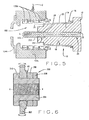
- a sub-assembly 300 including a connecting plate 302 is employed as shown in Figures 6 and 7 .
- the sub-assembly 300 must be assembled before threading a chock adjustment nut 304 onto the threaded end of the center rod 22.
- a trapping nut 306 and a jam nut 308 secure the connecting plate 302 against a flange 310 on the chock adjustment nut 304.
- a slight axial gap AG is required between the chock adjustment nut 304 and trapping nut 306, so the connecting plate 302 can spin freely about circumference of the chock adjustment nut 304, as required for lining up bolt holes in the connecting plate 302 with corresponding bolt holes in the adjustable chock end cover 104A.
- the inner circumferential surface of the connecting plate 302 is provided with a spherical or curved face, allowing the connecting plate 302 to pivot relative to the axis X-X to accommodate misalignment between the center rod 22 and the adjustable chock end cover 104A.
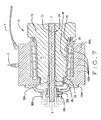
- the sub-assembly 300 is threaded onto the end of the center rod 22 as shown in Figure 7 until the connecting plate 302 makes contact with the adjustable chock's end cover 104A.
- the connecting plate 302 is then rotated to line up the bolt holes with the end cover 104A, for attachment thereto by suitable bolts (not shown).
- the combined end cover 104A and sub-assembly 300 is further secured to the center rod 22 by a setting nut 32, with a jam nut 34 additionally applied to the end of the center rod 22 to assure that relative rotation is prevented there between.
- the chocks 102 are secured after the sub-assembly 300 has been connected to the center rod 22 and the end cover 104A.
- the setting nut 32 (as shown in Fig.
- the sub-assembly 300 at the adjustment end of the roll assembly 10 is replaced with a precision controlled hydraulic cylinder assembly 400, such as shown in Figure 10 , having a hydraulically actuated piston 402 supported within a housing assembly 404.
- a connecting plate 405 is secured concentrically about the circumference of the housing 404 in much the same manner as is shown in Figure 6 , about the adjusting nut, and is engaged with the end cover 104A of the adjustable end chock 102L, while a coupling means, such as a sleeve 406 abutting the setting nut 32, engages the actuated piston with the axial end of the axial center rod 22.
- the inner circumferential surface of the connecting plate 405 is provided with spherical or curved faces, allowing the connecting plate 405 to pivot relative to the axis X-X to accommodate misalignment between the center rod 22 and the adjustable chock end cover 104A.
- controlled axial position adjustments to the actuated piston 402 of the hydraulic cylinder assembly 404 alter or maintain the bearing settings during the transition from a cold start-up state to a steady-state operating temperature for the rolling mill by exerting forces between the end cover 104A of the adjustable end chock 102L and the axial centering rod 22.
- a hydraulic cylinder assembly 404 may be utilized to effect adjustment of the bearing setting in a variety of configurations which may differ from that shown in Figure 10 .
- the hydraulic cylinder assembly 404 may be configured to concentrically surround the axial center rod 22, and to exert an actuating force between the setting nut 32 threaded to an end of the axial center rod 22 and the end cover 104A of the adjustable chock 102L.
- Setup for the hydraulic cylinder embodiment shown in Figure 10 first requires that the hydraulic cylinder assembly 404 be coupled to the adjustable chock 102L in an unpressurized state. Rotation of the roll 10 is begun. Next, during rotation of the roll 10 about the axis X, torque is applied to the setting nut 32 at the end of the axial center rod 22 until a desired preload force is achieved (8500 Ibs for example) based on monitoring from associated sensors. Next, shims (not shown) are inserted into the assembly adjacent the setting nut 32, having a thickness selected to correspond to the desired preload force and cold setting values, and the jam nut 34 is tightened onto the axial center rod 22, entrapping the shims (not shown) against the setting nut 32.
- the hydraulic cylinder assembly 404 is coupled to a controlled source of hydraulic pressure, and the bearing setting can be dynamically controlled as required to maintain the desired settings by introducing or removing hydraulic fluid from hydraulic cylinder assembly 404 through appropriate passages 408, allowing the piston 402 to move within the established tolerance range.
- FIG. 11-13 assembly of an alternate embodiment of the roll 10 is shown.
- the center rod 22 is initially passed through the roll 10 from the end where the non-adjustable chock 102R will be fitted, to the end of the roll 10 where an adjustable chock 102L is disposed, as is seen in Figure 11 .
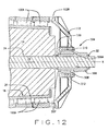
- an annular spacer 500 is welded to the center rod 22 axially inward from the threaded end to form a fixed shoulder against which the non-adjustable chock 102R can be secured, as best seen in Figure 12 .
- a bearing assembly 100 is preassembled into the interior of the chock 102R, and clamped tightly through the bearing cups as described above.
- the plain spherical assembly 504 includes an inner sleeve 506 adapted to fit about the center rod 22, an annular bearing member 508 having a spherical outer diameter surface pre-assembled onto the inner sleeve 506, and a mating outer bearing member 510 having a matching spherical inner diameter surface axially secured to the end cover 502 by a receiving element 512.
- the bearing engagement between the annular bearing member 508 and the outer bearing member 510 accommodate axial misalignment between the end cover 502 and the center rod 22, while transmitting only pure thrust load there between.
- the end cover 502 must be robust in design to absorb the net external thrust that will be absorbed through the center rod 22.
- the threaded axial end of the center rod 22 is passed through the plain spherical assembly 504 as shown in Figure 12 .
- the plain spherical assembly's 504 primary function is to reduce the potential for bending loads to be transmitted to the center rod 22 when the chock 102R tilts or rotates under load. Instead, the center rod 22 will be acting under a pure thrust load.
- the center rod 22 be under a pure thrust load for three reasons: a) bending of the center rod 22 would increase maximum stress, requiring larger rod diameter; b) bending of the center rod 22 would require larger clearance between the rod OD (stationary) and inner diameter of the roll bore 24 during rotation to assure that there is no contact between them during operation of the roll assembly 10; and c) to minimize any tilt restraint of the chocks 102R and 102L under load.
- the plain spherical assembly 504 will remain "stationary" with no rotation, allowing for the chock 102R to move relative there to, about the axis X.
- the entire mounting arrangement (including the end cover 502), is assembled over the end of the center rod 22 as an complete unit that will be clamped to the chock face of the non-adjustable chock 102R. While this is not a necessity, it reduces the number of components to be handled during the assembly process.
- the mounting arrangement consists of the inner sleeve 506 seated about the end of the center rod 22, abutting the fixed shoulder 500.
- the plain spherical element 508 is carried on the outer diameter of the sleeve 506, and is secured against a shoulder 506A of the sleeve by a jam nut or retainer 507 threaded onto the outer diameter of the sleeve 506.
- the plain spherical element 508 is, in turn, received within a corresponding spherical bearing surface of the outer bearing member 510 secured within an axial opening of the chock end cover 502.
- the chock end cover 502 in turn, is seated and secured against the axial face of the chock and bearing assembly mounted about the roll neck 14.
- a temporary device 22 may be employed as previously shown in Figures 4A and 4B to keep the chock 102R from falling off the end of the roll, when transitioning over to assembly the adjustable chock 102L at the opposite axial end.
- a second bearing assembly is preassembled into the adjustable side chock 102L, and clamped tightly through the cups.
- the end cover 502 must be robust in design to absorb the net external thrust that will be absorbed through the center rod 22.
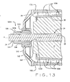
- the free end of the center rod 22 is passed through the plain spherical assembly 504A as shown in Figure 13 .
- the intention of the plain spherical assembly 504A is to eliminate any potential for bending loads to be transmitted to the center rod 22 if the chock 102L tilts or rotates under load. Instead, the center rod 22 will be acting under pure thrust load. As previously stated, it is preferable that the center rod 22 be under a pure thrust load for three reasons: a) bending of the center rod 22 would increase maximum stress, requiring a larger rod diameter; b) bending of the center rod 22 would require larger clearance between the rod OD (stationary) and inner diameter of the roll bore 24 to assure that there is no contact between them during operation of the roll assembly 10; and c) to minimize any tilt restraint of the chocks 102R and 102L under load. The plain spherical assembly 504A will remain "stationary" with no rotation, allowing for the chock 102L to move relative there to, about the axis X.
- the entire mounting arrangement (including the end cover 502), is assembled over the free end of the center rod 22 as an complete unit that will be clamped to the chock face of the bearing assembly 100. While this is not a necessity, it reduces the number of components to be handled during the assembly process.
- the mounting arrangement at the adjustment or operator side chock 102L is generally similar to that of the non-adjustable chock 102R, and consists of a sleeve (Chock Adjusting Device) 505 seated about the end of the center rod 22.
- the sleeve 505 includes a pilot surface 505B about the axial bore at the inboard end to facilitate assembly of the axial center rod 22 from an "off-center" position.
- a plain spherical element 508 is carried on the outer diameter of the sleeve 505, and is secured against a shoulder 505A of the sleeve 505 by a jam nut or retainer 507 threaded onto the outer diameter of the sleeve 505.
- the plain spherical element 508 is received within a corresponding spherical bearing surface of the outer bearing member 510 secured within an axial opening of the chock end cover 502.
- the chock end cover 502 in turn, is seated against the axial face of the chock 102L and bearing assembly mounted about the roll neck 14.
- a jam or adjustment nut 32 is threaded loosely onto the exposed end of the rod.
- the sleeve with internal threads is further tightened onto the center rod 22 with appropriate nut torque until a desired preload force is imposed on the adjustable or operator side chock 102L.
- shims may be inserted between the adjustment nut 32 and the axially outboard end of the sleeve 505 to set a suitable clearance. Once the adjustment nut 32 is threaded to the desired position, the shims may be removed and the sleeve backed off from its "preload position" to obtain the desired clearance in both bearing assemblies.
- a second lock nut 34 is threaded onto the free end of the axial center rod 22, and abutted against the adjustment nut 32 to lock the setting in place and to prevent back-off during operation of the roll assembly 10.
- a cold setting for the bearing assemblies 100 must be established as shown in Figure 9 , before final assembly into a mill stand.
- a state of preload is needed in order to establish a "reference point" for establishing a "final cold setting”.
- This final cold setting will typically be one of endplay in order to cope with the thermal expansion of the roll 12 that naturally occurs when the roll 12 is operating within the mill environment during the rolling process. As a mill begins to operate, the temperature of the roll 12 will rise, and the bearing's clearance setting will decrease during this transient setting phase. The final operating setting in the mill will be reached when the steady-state temperatures have stabilized.
- the transition between initial cold setting and final operating setting is denoted in Fig 9 by the curve labeled "Operating Setting, Uncompensated”.
- the temperature of the axial center rod 22 can be controlled to compensate for the roll's thermal expansion (denoted by the curve in Fig 9 labelled “Center Rod Thermal Expansion"), then it is possible to reduce the bearing systems' initial cold setting nearer to it desired operating setting, denoted by the curve in Fig 9 labeled "Operating Setting, Compensated”.
- the systems and methods disclosed herein enable adjustments to be made to the settings of the bearing assemblies 100 in each chock 102 to accommodate the thermal growth of the roll assembly 10 from the cold start condition to the steady-state temperature, allowing the bearing settings at the steady-state temperature to remain optimal.
- Each method includes a prior bearing analysis of the link between preload force and dimensional preload, which can be readily obtained through known analysis programs.
- a typical setting curve is produced as a function of the bearing's geometry.
- a preload force required to achieve 0.020" preload is 8500 lbs. It is also known that the nominal nut torque required to achieve 8500 lbs of preload force is 600 ft-lbs. So there are two ways to establish this preload force: Using chock adjustment nut torque (if a strain gage is not used), the roll must be rotated slowly on the set-up stand as the torque is increased on the chock adjustment nut 505 (on the side of the adjustable chock 102L). The torque on the chock adjustment nut 505 is continually increased until finally achieving the 600 ft-lb goal. The roll 12 is then allowed to rotate for a few minutes to assure that the nut torque remains steady. Torque is re-applied if necessary, until the chock adjustment nut 505 no longer moves after applying the 600 ft-lbs of torque to it.
- a preferred method is to use a measure of the preload force (if a strain gage is part of the center rod 22 design): The same procedure is used, applying the torque to the chock adjustment nut 505 while the roll 12 is rotating. However, this time the forces are observed from the instrumentation attached to the strain gage associated with the center rod 22. Once 8500 lbs of preload force is achieved, the rotation of the roll 12 is continued for several minutes. The nut torque may have to be reapplied if the measured preload force drops off after the initial 8500 lbs of preload force is first achieved. Once this force reaches a steady-state, the roll 12 can be considered to be in a condition of 0.020" preload, and the reference preload setting has now been established.
- the next step is to establish the cold setting which will achieve the desired operating setting at which the bearings will operate once the mill reaches a steady-state operating condition.
- the cold mounted setting begins at approximately 0.180" per assembly, or 0.015" radial clearance.
- the temperature of the roll 12 will grow until it reaches a steady-state temperature.
- the mounted setting is measured at as 0.100" - meaning that the thermal growth of the roll 12 is 0.080", since the cold setting began at 0.180". It is important to note that the operating setting must be measured quickly after exiting the mill stand to get an accurate reading of the warm operating setting.
- the cold setting (initially in endplay) is established with an estimate of how much the thermal expansion of the roll 12 will reduce the setting.
- the cold setting is conservatively selected to prevent the clearances from being removed completely by the thermal expansion, and to avoid operation in a preload setting.
- estimates are made of the anticipated thermal changes, from which the initial setting is established.
- the cold setting (initial) is set to be equal to the operating setting (desired) combined with the thermal expansion (estimated) of the roll 12. With this initial setting, adjustments can and should be made by measuring the operating setting (measured) after the roll 12 is removed from the mill.
- the operating setting (measured) is within a tolerance of the operating setting (desired), no further changes are required. If the operating setting (measured) exceeds the operating setting (desired), then the cold setting is reduced by an amount equal to the difference between the measured and desired operating settings. Finally, if the operating clearance (measured) is less than the operating clearance (desired), then the cold setting is increased by an amount equal to the difference between the measured and desired operating settings.
- the bearing assembly 100 settings are stabilized through the transition setting phase as the mill roll progresses towards the steady-state operating condition.
- This permits control of the operating setting to a lower clearance under cold start-up conditions while avoiding a condition of bearing preload after the mill reaches thermal equilibrium during mill operation by providing a means of temperature control for the center rod 22 coupling the opposite chocks 102 and bearing assemblies through the roll 12.
- the temperature control means may consist of a heat source applied to the center rod 22 which is controlled to heat the center rod 22 (increasing endplay in the bearings) at the same rate that the roll 12 heats up naturally (decreasing endplay) which occurs during the transition from cold start-up to steady-state operation of the mill.
- the center rod 22 may include a heating element axially disposed within the center rod 22. This allows the cold setting for the bearing assemblies 100 to be adjusted to correspond to the desired operating setting, so long as the thermal compensation is applied to the center rod 22 during the transition, thereby holding a consistent operating setting from cold start-up to the steady-state operation.
- centering bushings 28 in each end of the roll center bore 24 is eliminated, allowing for additional clearance of the center rod 22 through the roll 12.
- the center rod 22 will be naturally centered in the roll 12 by the seating of each bearing assembly 100 on each roll end.
Landscapes
- Engineering & Computer Science (AREA)
- General Engineering & Computer Science (AREA)
- Mechanical Engineering (AREA)
- Support Of The Bearing (AREA)
Description
- The present disclosure is related generally to bearings for supporting rollers in rolling mill applications, and in particular to a system and method for mounting roller support bearings.
- Two types of bearings find widespread use in such rolling mill machinery, those being the tapered roller bearing and the cylindrical roller bearing, each of which is capable of carrying heavy radial loads. Tapered roller bearings lend themselves to adjustment in that the axial positions of the supporting races relative to each other control the radial clearance or play, and may even eliminate the radial clearance altogether. This in turn provides control of the size of the load zone, that is the number of rollers in the bearing which are actually under load at any instant. Notwithstanding this capability, tapered roller bearings, when used to transmit extremely heavy loads such as in rolling mills, are usually manufactured with their tapered rollers arranged in four rows, and with the tapers of adjacent rows oriented oppositely. This makes adjustments in the field difficult, and for all practical purposes these multi-row bearings are adjusted at the factory through the selection of spacers. There the bearings are usually set with a slight amount of axial clearance. However, the profile of the raceway on the cone or inner race is not perfectly circular nor is its axis perfectly coincident with the axis of rotation. These imperfections cause runout.
- In one known arrangement,
EP 0425072 discloses a mill roll which is supported by its roll necks in tapered roller bearings each having several cones and corresponding cups and rows of tapered rollers between the raceways of each cone and cup. The tapered roller bearings are captured between a cone thrust ring and a fillet ring on a tapered roll neck surface. - Cylindrical roller bearings, on the other hand, cannot be adjusted, and since some radial clearance must exist between the rollers and the raceways in order to assemble the bearings, cylindrical roller bearings inherently will have runout, given that the inner race cannot be ground to a perfectly round condition. Despite the inherent runout, the use of cylindrical roller bearings in mill rolls affords easier control over the runout derived from the manufacturing tolerances. For example, the raceway of the inner race, once that race is installed on the roll neck, may be ground reasonably true with respect to the axis of the roll. Typically, the mill roll, with the inner races of its bearings in place, is placed between centers with the roll neck later supported on steady rests. The grinding eliminates much of the runout caused by manufacturing tolerances in the roll neck and race, and the expansion tolerance of the press fit. However, some runout will remain due primarily to imperfections in the grinding operation itself, for the inner race may have one or more lobes in its profile after grinding.
- The option of grinding to eliminate runout has not been available for tapered roller bearings, primarily because their races are at different inclinations, and the inner races or cones have ribs, all of which interfere with the grinding operations. Furthermore, alteration of a radial dimension on a tapered raceway affects the axial dimensions in the bearing, and requires the use of additional spacers or shims to compensate for the change in the axial dimension.
- If the bearings supporting a roll in a rolling mill are improperly set, various problems can ensue. For bearings which have too much endplay, there is an increased chance of roller skidding (i.e. low load zone) and lower bearing life (as the load zone decreases, the load per roller ratio increases, and bearing life decreases.) Conversely, for bearings set with too much preload, there is the risk of bearing burn-up, which is generally a catastrophic damage and cannot be easily repaired.
- Accordingly, it would be advantageous to provide a method and apparatus to facilitate the proper mounting and setting of roller bearings such as those used to support back up rolls in rolling mill applications. It would be further advantageous to provide such a method and apparatus to achieve good control over the bearing settings from a cold state through steady-state operating conditions.
- According to the present invention there is provided a method for assembling bearing assemblies onto the axial ends of a mill roll having a roll portion with reduced diameter roll necks at each axial end, and an axial bore, comprising:
- disposing an axial center rod within said axial bore of the mill roll, said axial center rod having an axial length greater than the axial length of the mill roll;
- disposing tapered sleeves forming an inner ring for the bearing assemblies onto each roll neck of the mill roll;
- disposing a first bearing assembly comprising an outer ring and roller assembly within a non-adjustable end chock, said first bearing assembly having an axially open face for receiving the tapered sleeve mounted to a first roll neck of the mill roll, and an end-cover opposite from said axially open face, said end-cover having an axial opening for receiving an axial end of said axial center rod;
- positioning said first bearing assembly and said non-adjustable end chock on the first roll neck of the mill roll, such that said bearing assembly is in contact with an outer diameter surface of said tapered sleeve, and an axial end of said axial center rod passes through said axial opening in said end-cover;
- securing said first bearing assembly and said non-adjustable end chock to said axial end of said axial center rod;
- disposing a second bearing assembly comprising a second outer ring and second roller assembly within an adjustable end chock, said second bearing assembly having an axially open face for receiving a second tapered sleeve mounted to a second roll neck of the mill roll, and an end-cover opposite from said axially open face, said end-cover having an enlarged axial opening for receiving a free axial end of said axial center rod;
- positioning said second bearing assembly and said adjustable end chock on the second roll neck of the mill roll, such that said bearing assembly is in contact with an outer diameter surface of second tapered sleeve, and said free axial end of said axial center rod passes through said enlarged axial opening in said end-cover;
- securing said second bearing assembly and said adjustable end chock to the free axial end of said axial center rod; and
- establishing a bearing setting for said first and second bearing assemblies between said end chocks, 1 through said axial center rod.
- Preferred features of the present invention are set out in the attached sub-claims.
- Briefly stated, the present disclosure provides a method for assembling a set of bearings onto a mill roll and for establishing a required bearing setting. The mill roll is configured to receive a set of bearings at each axial end, with the bearings contained within supporting chocks adapted for placement within a mill housing. The chock and bearing at a first end of the roll is positioned first, and coupled to the first end by a center rod passing through an axial bore of the roll. The chock and bearing at the second end of the roll is then positioned onto the opposite end of the roll, and a connecting sub-assembly is secured to the second end of the center rod. The connecting sub-assembly engages the second chock and bearing, and is axially adjusted to achieve a desired bearing setting.
- The foregoing features, and advantages set forth in the present disclosure as well as presently preferred embodiments will become more apparent from the reading of the following description in connection with the accompanying drawings.
- In the accompanying drawings which form part of the specification:
-
Figures 1A and 1 B illustrate a roll supported on a set-up stand for assembly of the roll support bearings and chocks, with optional bushings inserted into the roll ends; -
Figure 2 illustrates the initial step in the installation process for placing the non-adjustable chock onto a roll end; -
Figure 3 illustrates the completed installation process for placing the non-adjustable chock onto a roll end; -
Figure 4A illustrates a sectional view of the roll with the non-adjustable chock secured to the roll end by a temporary restraint at the opposite end of the center rod; -
Figure 4B is an enlarged view of the temporary restraint inFig. 4A ; -
Figure 5 illustrate the initial step in the installation process for placing the adjustable chock onto a roll end opposite the non-adjustable chock; -
Figure 6 illustrates a sectional view of a connecting plate sub-assembly for securing the adjustable chock onto the roll end; -
Figure 7 illustrates the completion of the installation process for placing the adjustable chock onto the roll end with the connecting plate sub-assembly; -
Figure 8 is a sectional illustration of the roll with the adjustable and non-adjustable chocks installed; -
Figure 9 is a graph of Operating Setting vs. Time for an assembled roll, representing thermal expansion effects and compensation settings; -
Figure 10 illustrates a sectional view of an alternate embodiment employing a hydraulic cylinder to effect adjustment to the bearing setting; -
Figure 11 is a sectional view of an alternate embodiment of the roll system of the present disclosure, with end chocks incorporating plain spherical assemblies; -
Figure 12 is an enlarged sectional view of the non-adjustable chock at one end of the roll system ofFigure 11 ; and -
Figure 13 is an enlarged sectional view of the adjustable chock at a second end of the roll system ofFigure 11 . - Corresponding reference numerals indicate corresponding parts throughout the several figures of the drawings. It is to be understood that the drawings are for illustrating the concepts set forth in the present disclosure and are not to scale.
- The following detailed description illustrates the invention by way of example and not by way of limitation. The description enables one skilled in the art to make and use the present disclosure, and describes several embodiments, adaptations, variations, alternatives, and uses of the present disclosure, including what is presently believed to be the best mode of carrying out the present disclosure.
- A mill stand has
multiple rolls 10, each of which at its axial ends rotates in abearing assembly 100 which in turn is confined within a chock 102 that fits into a heavy end frame mounted securely on a supporting foundation. Actually, eachroll 10 is one of at least two rolls and possibly four, as the typical four-high mill stand has two work rolls between which a piece of metal to be worked passes, and in addition a pair of back-up rolls which are larger than the work rolls, and which serve to prevent the work rolls from deflecting under the separating force needed to reduce the metal piece's (or sheet's) thickness. As in any mill stand, the chocks 102 slide vertically relative to the end frames in which they are located, but are normally held together by large turn down screws which thread into the frame and bear against the chocks 102 for the upper back-up roll. Hydraulic pressure pistons controlled through a feedback loop may be used to vertically position the chocks 102 in lieu of the turn down screws, and are actually more commonly used in today's mill designs. - The bearing
assembly 100 of the present disclosure may be used to support either a work roll or back-up roll or both, although the latter is perhaps the primary application. The bearingassembly 100 classifies as a tapered roller bearing, and as such, is capable of taking thrust loads as well as the heavy radial loads imparted by the piece of metal which is worked by a supportedroll 10. Being one of a pair of tapered roller bearings 102, the bearingassembly 100 may also be adjusted between conditions of endplay and preload. - The
roll 10 turns about a longitudinal axis in the bearingassemblies 100, about an axis X of rotation which ideally is coincident to its own center axis. Theroll 10 includes aroll body 12, which may be cylindrical, and aroll neck 14 at each end of the body. Eachroll neck 14 has afillet ring 16 where it merges into the body, and beyond the fillet ring 16 a taperedsurface 18 on which thebearing 100 is seated. Thistapered surface 18 may be directly formed into the roll neck, or preferably, consists of a taperedsleeve 20 mounted to theroll neck 14, and abutting thefillet ring 16 - Bearing assemblies for roll mills can be are often mounted on the roll in a Direct Mount Arrangement, and a typical bearing assembly will include four rows of rollers. An exemplary conventional roll mill bearing assembly may be seen in
U.S. Patent No. 4,938,615 to Baker , which is herein incorporated by reference. A unique feature of the direct mount arrangement is the inclusion of acenter rod 22 that extends through theaxial bore 24 of the back-up roll. This center rod (being stationary) is used to connect theright chock 102R to theleft chock 102L. Additionally, thiscenter rod 22 is used for conveniently establishing the clearance in the bearing system (two four-row assemblies) by first establishing the "reference preload setting", and then by backing off on a chock adjustment nut threaded to one end of the center rod 22 a predetermined distance to establish the bearing clearance prior to entry or placement of theroll 10 into a mill stand. - Initially when formed, the roll 10 (including both the
roll body 12 and rollnecks 14 on each end) is very conventional in nature. Theroll 10 is first turned on a lathe to achieve the desired roundness and dimensions, using a centering plug in each opening of theaxial bore 24 to provide centering for theroll 10 before turning on a lathe. These plugs are needed as well during a surface grinding process at a roll grinder to first support theroll 10 for finish grinding theroll neck extensions 14 prior to supporting theroll 10 on steady rests. The centering plugs must be removed after finish grinding to expose theaxial bore 24 that extends the axial length of theroll 10. - Once the
roll 10 has been finish ground, then the fillet rings 16 and taperedsleeves 20 of each bearingassembly 100 are disposed on theroll neck 14 with a press fit. Thetapered sleeves 20 are supplied with added grindstock, so that they can be finish ground after mounting onto theroll neck 14. This practice is typical of what is done today with the inner rings of cylindrical bearings. Once thetapered sleeves 20 have been mounted, theclamp ring 26 is installed at the outer end of eachtapered sleeve 20 to retain the axial position of the taperedsleeves 20. Once mounting is accomplished, theroll 10 is set back onto the steady rests of the roll grinder, for finish grinding the taperedsleeves 20 to the proper size and taper. - Preferably, the
roll 10 of the present disclosure is a back-up non-driven roll. Often, forged rolls for back-up rolls (40.0 inch roll body or larger) include anaxial bore 22 through the center to optimize the forging process (and prevent eventual cracks from occurring). The remainder are formed by a casting process (and without this "automatic" hole in the center"). Cast rolls may be found in plate mills and some hot mills, but any reputable flat products mill would use a forgedroll 10 for all cold mills and most hot mills. - The embodiments of the present disclosure back-up roll system design are intended as a potential replacement for all mills rolling flat products, including plate mills, hot mills, cold mills, temper mills, and foil mills. In basic terms, the bearing
assembly 100 is designed for these applications where thrust loads are low (0.5% to 2% of separating force). The mounting system presented herein is intended provide for a simple mounting procedure, with less potential for bearing damage during the mounting process, and control of the bearing's clearance throughout the life of the bearingassembly 100. - Turning to
Figures 1 A and 1 B , one new piece of "Capital Equipment" that will be required for the back-up roll system of the present disclosure is a "Set-Up Stand" 1. The primary function of this set-upstand 1 is to allow for rotation of theroll 10 during the bearing assembly set-up process, where the bearings' system clearance is established. It is suggested that theroll 10 always be rotating whenever the chock adjusting nut is being rotated to affect bearing setting - either by loosening or tightening the setting. However, the first several steps of assembling both chocks 102 onto theroll 10 will be done with theroll 10 held stationary. -
Step 1 of the Process is shown inFigures 1 A and 1 B . Any centering plugs present from the roll forming process are removed, and replace withoptional bushings 28 in each end of theroll 10. Note that theroll 10 may require acounterbore 28A in the axial ends of theroll 10 to accept both the centering plug and bushing 28 (both press-fit into the roll 10). Thesebushings 28 include shallow angle chamfers for piloting thecenter rod 22 axially through theaxial bore 24 of theroll 10. Once thebushings 28 have been press fit into place, thecenter rod 22 will be passed through theroll 10 from the axial end where anon-adjustable chock 102R will be fitted, to the opposite axial end of theroll 10 where chock lateral adjustment can be made to theadjustable chock 102L. Those of ordinary skill in the art will recognize that the designation of one chock 102 as adjustable merely denotes the side at which the chock lateral adjustment will take place, and is not intended to limit the present invention to adjustment at only the left side of theroll 10. An axial end of thecenter rod 22 with ashoulder nut 30 secured to it will establish the end for placement of thenon-adjustable chock 102R on theroll neck 14. - Turning to
Figures 2 and 3 , the cup-spacer-roller assemblies of each bearing 100 are preassembled into thechock 102R, and clamped tightly in place. Anend cover 104 is secured tightly to the outer face of thenon-adjustable chock 102R. Theend cover 104 is robust in design to absorb the net external thrust that will be absorbed through thecenter rod 22 when fully assembled. Generally, an overhead crane C is all that is needed for assembling the chock-roller assembly over the inner rings or taperedsleeve 20 on theroll neck 14, however, other lifting machines may be utilized for assembling the chocks 102 if available. Here, the radial clearance is exceptionally high when therollers 100A first pass over the roll neck or taperedsleeve 20. Preferably, this radial clearance is equal to the width of the bearing 100 divided by 12. For example, a 36"wide bearing 100 will have a 3" diametral clearance (1 1/2" radial clearance) when passing over the small end of the taperedsleeves 20 that has a 1/12 taper on the diameter. - The
chock 102 R will stop moving axially inward after therollers 100A have made final contact with the inner rings on the taperedsleeve 20, as shown inFigure 3 . At this point, thenon-adjustable chock 102R remains secured with the overhead crane C or other lifting mechanism. Theend cover 104 is next secured between theshoulder nut 30 and a settingnut 32. Ajam nut 34 is additionally applied to the end of thecenter rod 22 to assure that theend cover 104 remains firmly secure on thecenter rod 22 and that the center rod is not free to rotate relative to theend cover 104. Anoptional dust cover 105 may be disposed over the exposed end. Note, however at this stage, thechock 102R is not completely secure from sliding down the taper of the inner rings or taperedsleeve 20. Thechock 102R is only connected to thecenter rod 22 that is "loose" within the center bore 24 of theroll 10. To prevent thecenter rod 22 from pulling through theroll 10, atemporary holding device 200, shown inFigures 4A and 4B may be secured by anaxial bolt 202 on the opposite axial end of thecenter rod 22 to keep thechock 102R from falling off the end of theroll 10, when transitioning over to assembly the "adjustable chock" on the opposite axial end. (Figure 5 ). - Next, as shown in
Figures 5-7 , theadjustable chock 102L is secured to theroll 10 axially opposite from thenon-adjustable chock 102R. Theadjustable chock 102L includes anend cover 104A rigidly fixed to the outer axial face of thechock 102L. The overhead crane C or lift mechanism can be used (similar to the non-adjustable side) to move thechock 102L and associatedbearing assembly 100 into position on theroll neck 14. - Once the bearing
assembly 100 and chock 102L have been brought to rest against the taperedsleeve 20 inner rings, a temporary strap T, as shown inFigure 7 , is used to connect the twochock assemblies roll 10. Once this has been accomplished, thetemporary restraint 200 on the axial end of thecenter rod 22 can safely be removed. - To secure the
adjustable chock 102L to the axial end of theroll 10 and thecenter rod 22, a sub-assembly 300 including a connectingplate 302 is employed as shown inFigures 6 and7 . The sub-assembly 300 must be assembled before threading achock adjustment nut 304 onto the threaded end of thecenter rod 22. A trappingnut 306 and ajam nut 308 secure the connectingplate 302 against aflange 310 on thechock adjustment nut 304. However, a slight axial gap AG is required between thechock adjustment nut 304 and trappingnut 306, so the connectingplate 302 can spin freely about circumference of thechock adjustment nut 304, as required for lining up bolt holes in the connectingplate 302 with corresponding bolt holes in the adjustablechock end cover 104A. Preferably, the inner circumferential surface of the connectingplate 302 is provided with a spherical or curved face, allowing the connectingplate 302 to pivot relative to the axis X-X to accommodate misalignment between thecenter rod 22 and the adjustablechock end cover 104A. - The sub-assembly 300 is threaded onto the end of the
center rod 22 as shown inFigure 7 until the connectingplate 302 makes contact with the adjustable chock'send cover 104A. The connectingplate 302 is then rotated to line up the bolt holes with theend cover 104A, for attachment thereto by suitable bolts (not shown). Thecombined end cover 104A andsub-assembly 300 is further secured to thecenter rod 22 by a settingnut 32, with ajam nut 34 additionally applied to the end of thecenter rod 22 to assure that relative rotation is prevented there between. The chocks 102 are secured after the sub-assembly 300 has been connected to thecenter rod 22 and theend cover 104A. The setting nut 32 (as shown inFig. 8 ), is used to establish an overall bearing clearance, while thejam nut 34 is used to secure the position of the setting nut. At this point, both chocks 104L and 104R are secured on each end of theroll 10, and the temporary strap T can be removed, together with any remaining connections to the supporting crane C or other lift mechanism, as shown inFigure 8 - In a optional configuration, the sub-assembly 300 at the adjustment end of the
roll assembly 10 is replaced with a precision controlledhydraulic cylinder assembly 400, such as shown inFigure 10 , having a hydraulically actuatedpiston 402 supported within ahousing assembly 404. A connectingplate 405 is secured concentrically about the circumference of thehousing 404 in much the same manner as is shown inFigure 6 , about the adjusting nut, and is engaged with theend cover 104A of the adjustable end chock 102L, while a coupling means, such as asleeve 406 abutting the settingnut 32, engages the actuated piston with the axial end of theaxial center rod 22. Preferably, the inner circumferential surface of the connectingplate 405 is provided with spherical or curved faces, allowing the connectingplate 405 to pivot relative to the axis X-X to accommodate misalignment between thecenter rod 22 and the adjustablechock end cover 104A. - In each embodiment, controlled axial position adjustments to the actuated
piston 402 of thehydraulic cylinder assembly 404 alter or maintain the bearing settings during the transition from a cold start-up state to a steady-state operating temperature for the rolling mill by exerting forces between theend cover 104A of the adjustable end chock 102L and the axial centeringrod 22. - Those of ordinary skill in the art will recognize that a
hydraulic cylinder assembly 404 may be utilized to effect adjustment of the bearing setting in a variety of configurations which may differ from that shown inFigure 10 . For example, thehydraulic cylinder assembly 404 may be configured to concentrically surround theaxial center rod 22, and to exert an actuating force between the settingnut 32 threaded to an end of theaxial center rod 22 and theend cover 104A of theadjustable chock 102L. - Setup for the hydraulic cylinder embodiment shown in
Figure 10 first requires that thehydraulic cylinder assembly 404 be coupled to theadjustable chock 102L in an unpressurized state. Rotation of theroll 10 is begun. Next, during rotation of theroll 10 about the axis X, torque is applied to the settingnut 32 at the end of theaxial center rod 22 until a desired preload force is achieved (8500 Ibs for example) based on monitoring from associated sensors. Next, shims (not shown) are inserted into the assembly adjacent the settingnut 32, having a thickness selected to correspond to the desired preload force and cold setting values, and thejam nut 34 is tightened onto theaxial center rod 22, entrapping the shims (not shown) against the settingnut 32. The shims are then removed without altering the settings of thejam nut 34, and the settingnut 32 is threaded back to thejam nut 34 establishing the cold setting positions. Once the assembled and setmill roll 10 is placed in the mill stand, thehydraulic cylinder assembly 404 is coupled to a controlled source of hydraulic pressure, and the bearing setting can be dynamically controlled as required to maintain the desired settings by introducing or removing hydraulic fluid fromhydraulic cylinder assembly 404 throughappropriate passages 408, allowing thepiston 402 to move within the established tolerance range. - Turning next to
Figures 11-13 , assembly of an alternate embodiment of theroll 10 is shown. Thecenter rod 22 is initially passed through theroll 10 from the end where thenon-adjustable chock 102R will be fitted, to the end of theroll 10 where anadjustable chock 102L is disposed, as is seen inFigure 11 . At one end of thecenter rod 22, anannular spacer 500 is welded to thecenter rod 22 axially inward from the threaded end to form a fixed shoulder against which thenon-adjustable chock 102R can be secured, as best seen inFigure 12 . - At the non-adjustable or "drive side"
chock 102R, a bearingassembly 100 is preassembled into the interior of thechock 102R, and clamped tightly through the bearing cups as described above. Anend cover 502 incorporating a plainspherical assembly 504 through which the end of thecenter rod 22 passes axially, is secured tightly to the outer face of thenon-adjustable chock 102R. The plainspherical assembly 504 includes aninner sleeve 506 adapted to fit about thecenter rod 22, anannular bearing member 508 having a spherical outer diameter surface pre-assembled onto theinner sleeve 506, and a matingouter bearing member 510 having a matching spherical inner diameter surface axially secured to theend cover 502 by a receivingelement 512. The bearing engagement between theannular bearing member 508 and theouter bearing member 510 accommodate axial misalignment between theend cover 502 and thecenter rod 22, while transmitting only pure thrust load there between. - The
end cover 502 must be robust in design to absorb the net external thrust that will be absorbed through thecenter rod 22. In order to absorb any misalignment between thecenter rod 22 and thechock 102R, the threaded axial end of thecenter rod 22 is passed through the plainspherical assembly 504 as shown inFigure 12 . The plain spherical assembly's 504 primary function is to reduce the potential for bending loads to be transmitted to thecenter rod 22 when thechock 102R tilts or rotates under load. Instead, thecenter rod 22 will be acting under a pure thrust load. It is preferable that thecenter rod 22 be under a pure thrust load for three reasons: a) bending of thecenter rod 22 would increase maximum stress, requiring larger rod diameter; b) bending of thecenter rod 22 would require larger clearance between the rod OD (stationary) and inner diameter of the roll bore 24 during rotation to assure that there is no contact between them during operation of theroll assembly 10; and c) to minimize any tilt restraint of thechocks spherical assembly 504 will remain "stationary" with no rotation, allowing for thechock 102R to move relative there to, about the axis X. - The entire mounting arrangement (including the end cover 502), is assembled over the end of the
center rod 22 as an complete unit that will be clamped to the chock face of thenon-adjustable chock 102R. While this is not a necessity, it reduces the number of components to be handled during the assembly process. Specifically, as seen inFigure 12 , the mounting arrangement consists of theinner sleeve 506 seated about the end of thecenter rod 22, abutting the fixedshoulder 500. The plainspherical element 508 is carried on the outer diameter of thesleeve 506, and is secured against ashoulder 506A of the sleeve by a jam nut orretainer 507 threaded onto the outer diameter of thesleeve 506. The plainspherical element 508 is, in turn, received within a corresponding spherical bearing surface of theouter bearing member 510 secured within an axial opening of thechock end cover 502. Thechock end cover 502 in turn, is seated and secured against the axial face of the chock and bearing assembly mounted about theroll neck 14. - With the
center rod 22 end passing through thesleeve 506, a suitable jam or retainingnut 32 is threaded onto the exposed end of the rod, and tightened against the axially outboard end of thesleeve 506, which in turn, is trapped against the fixedshoulder 500 on thecenter rod 22, thereby securing the entire mounting arrangement of the drive side chock 102R in a fixed arrangement relative to theaxial center rod 22. Note, however, at this point, thechock 102R is still not completely secure from sliding down the taper surface of the inner rings 20. Thechock 102R is only connected to thecenter rod 22, which itself is "loose" in theroll 10. To prevent thecenter rod 22 from pulling through theroll 10, atemporary device 22 may be employed as previously shown inFigures 4A and 4B to keep thechock 102R from falling off the end of the roll, when transitioning over to assembly theadjustable chock 102L at the opposite axial end. - At the opposite axial end (adjustable or operator side) of the
roll assembly 10, a second bearing assembly is preassembled into the adjustable side chock 102L, and clamped tightly through the cups. Asecond end cover 502 incorporating a second plainspherical assembly 504A through which the free end of theaxial center rod 22 passes, is secured tightly to the outer face of theadjustable chock 102L. As with thenon-adjustable chock 102R, theend cover 502 must be robust in design to absorb the net external thrust that will be absorbed through thecenter rod 22. In order to absorb any misalignment between thecenter rod 22 and thechock 102L, the free end of thecenter rod 22 is passed through the plainspherical assembly 504A as shown inFigure 13 . The intention of the plainspherical assembly 504A is to eliminate any potential for bending loads to be transmitted to thecenter rod 22 if thechock 102L tilts or rotates under load. Instead, thecenter rod 22 will be acting under pure thrust load. As previously stated, it is preferable that thecenter rod 22 be under a pure thrust load for three reasons: a) bending of thecenter rod 22 would increase maximum stress, requiring a larger rod diameter; b) bending of thecenter rod 22 would require larger clearance between the rod OD (stationary) and inner diameter of the roll bore 24 to assure that there is no contact between them during operation of theroll assembly 10; and c) to minimize any tilt restraint of thechocks spherical assembly 504A will remain "stationary" with no rotation, allowing for thechock 102L to move relative there to, about the axis X. - The entire mounting arrangement (including the end cover 502), is assembled over the free end of the
center rod 22 as an complete unit that will be clamped to the chock face of the bearingassembly 100. While this is not a necessity, it reduces the number of components to be handled during the assembly process. Specifically, as seen inFigure 13 , the mounting arrangement at the adjustment or operator side chock 102L is generally similar to that of thenon-adjustable chock 102R, and consists of a sleeve (Chock Adjusting Device) 505 seated about the end of thecenter rod 22. Thesleeve 505 includes apilot surface 505B about the axial bore at the inboard end to facilitate assembly of theaxial center rod 22 from an "off-center" position. A plainspherical element 508 is carried on the outer diameter of thesleeve 505, and is secured against a shoulder 505A of thesleeve 505 by a jam nut orretainer 507 threaded onto the outer diameter of thesleeve 505. The plainspherical element 508 is received within a corresponding spherical bearing surface of theouter bearing member 510 secured within an axial opening of thechock end cover 502. Thechock end cover 502 in turn, is seated against the axial face of thechock 102L and bearing assembly mounted about theroll neck 14. - With the free end of the
axial center rod 22 passing through thesleeve 505, a jam oradjustment nut 32 is threaded loosely onto the exposed end of the rod. The sleeve with internal threads is further tightened onto thecenter rod 22 with appropriate nut torque until a desired preload force is imposed on the adjustable or operator side chock 102L. Those of ordinary skill in the art will recognize that shims may be inserted between theadjustment nut 32 and the axially outboard end of thesleeve 505 to set a suitable clearance. Once theadjustment nut 32 is threaded to the desired position, the shims may be removed and the sleeve backed off from its "preload position" to obtain the desired clearance in both bearing assemblies. Asecond lock nut 34 is threaded onto the free end of theaxial center rod 22, and abutted against theadjustment nut 32 to lock the setting in place and to prevent back-off during operation of theroll assembly 10. - For each embodiment, once the chocks 102 are secured to the
center rod 22 of theroll assembly 10, a cold setting for the bearingassemblies 100 must be established as shown inFigure 9 , before final assembly into a mill stand. A state of preload is needed in order to establish a "reference point" for establishing a "final cold setting". This final cold setting will typically be one of endplay in order to cope with the thermal expansion of theroll 12 that naturally occurs when theroll 12 is operating within the mill environment during the rolling process. As a mill begins to operate, the temperature of theroll 12 will rise, and the bearing's clearance setting will decrease during this transient setting phase. The final operating setting in the mill will be reached when the steady-state temperatures have stabilized. The transition between initial cold setting and final operating setting is denoted inFig 9 by the curve labeled "Operating Setting, Uncompensated". Alternatively, if the temperature of theaxial center rod 22 can be controlled to compensate for the roll's thermal expansion (denoted by the curve inFig 9 labelled "Center Rod Thermal Expansion"), then it is possible to reduce the bearing systems' initial cold setting nearer to it desired operating setting, denoted by the curve inFig 9 labeled "Operating Setting, Compensated". The systems and methods disclosed herein enable adjustments to be made to the settings of the bearingassemblies 100 in each chock 102 to accommodate the thermal growth of theroll assembly 10 from the cold start condition to the steady-state temperature, allowing the bearing settings at the steady-state temperature to remain optimal. - There are several methods that could be used to establish the dimensional preload reference point for the
roll assembly 10. Each method includes a prior bearing analysis of the link between preload force and dimensional preload, which can be readily obtained through known analysis programs. A typical setting curve is produced as a function of the bearing's geometry. - As an example, to establish a preload dimensional setting of 0.020" preload as the reference point, consider that a preload force required to achieve 0.020" preload is 8500 lbs. It is also known that the nominal nut torque required to achieve 8500 lbs of preload force is 600 ft-lbs. So there are two ways to establish this preload force: Using chock adjustment nut torque (if a strain gage is not used), the roll must be rotated slowly on the set-up stand as the torque is increased on the chock adjustment nut 505 (on the side of the
adjustable chock 102L). The torque on thechock adjustment nut 505 is continually increased until finally achieving the 600 ft-lb goal. Theroll 12 is then allowed to rotate for a few minutes to assure that the nut torque remains steady. Torque is re-applied if necessary, until thechock adjustment nut 505 no longer moves after applying the 600 ft-lbs of torque to it. - Alternatively, a preferred method is to use a measure of the preload force (if a strain gage is part of the
center rod 22 design): The same procedure is used, applying the torque to thechock adjustment nut 505 while theroll 12 is rotating. However, this time the forces are observed from the instrumentation attached to the strain gage associated with thecenter rod 22. Once 8500 lbs of preload force is achieved, the rotation of theroll 12 is continued for several minutes. The nut torque may have to be reapplied if the measured preload force drops off after the initial 8500 lbs of preload force is first achieved. Once this force reaches a steady-state, theroll 12 can be considered to be in a condition of 0.020" preload, and the reference preload setting has now been established. - With the reference preload setting established, the next step is to establish the cold setting which will achieve the desired operating setting at which the bearings will operate once the mill reaches a steady-state operating condition. Continuing with this example, the cold mounted setting begins at approximately 0.180" per assembly, or 0.015" radial clearance. As the mill starts up and the rolling process begins, the temperature of the
roll 12 will grow until it reaches a steady-state temperature. At this point, the mounted setting is measured at as 0.100" - meaning that the thermal growth of theroll 12 is 0.080", since the cold setting began at 0.180". It is important to note that the operating setting must be measured quickly after exiting the mill stand to get an accurate reading of the warm operating setting. - There are two ways in which the cold setting may be established. In a first method of the present invention, the cold setting (initially in endplay) is established with an estimate of how much the thermal expansion of the
roll 12 will reduce the setting. The cold setting is conservatively selected to prevent the clearances from being removed completely by the thermal expansion, and to avoid operation in a preload setting. With knowledge of the mill speed, estimates are made of the anticipated thermal changes, from which the initial setting is established. Essentially, the cold setting (initial) is set to be equal to the operating setting (desired) combined with the thermal expansion (estimated) of theroll 12. With this initial setting, adjustments can and should be made by measuring the operating setting (measured) after theroll 12 is removed from the mill. If the operating setting (measured) is within a tolerance of the operating setting (desired), no further changes are required. If the operating setting (measured) exceeds the operating setting (desired), then the cold setting is reduced by an amount equal to the difference between the measured and desired operating settings. Finally, if the operating clearance (measured) is less than the operating clearance (desired), then the cold setting is increased by an amount equal to the difference between the measured and desired operating settings. - In a second method of the present invention, the bearing assembly 100 settings are stabilized through the transition setting phase as the mill roll progresses towards the steady-state operating condition. This permits control of the operating setting to a lower clearance under cold start-up conditions while avoiding a condition of bearing preload after the mill reaches thermal equilibrium during mill operation by providing a means of temperature control for the
center rod 22 coupling the opposite chocks 102 and bearing assemblies through theroll 12. The temperature control means may consist of a heat source applied to thecenter rod 22 which is controlled to heat the center rod 22 (increasing endplay in the bearings) at the same rate that theroll 12 heats up naturally (decreasing endplay) which occurs during the transition from cold start-up to steady-state operation of the mill. For example thecenter rod 22 may include a heating element axially disposed within thecenter rod 22. This allows the cold setting for the bearingassemblies 100 to be adjusted to correspond to the desired operating setting, so long as the thermal compensation is applied to thecenter rod 22 during the transition, thereby holding a consistent operating setting from cold start-up to the steady-state operation. - Once the
roll assembly 10 is installed within the mill housing it will be recognized, that no mill modifications are needed to adapt the present embodiments described herein to an existing mill. Further, for new mills, this same "keeper plate" technology used for latching the operator side chock to the mill that has existed for many years would remain intact for new mills built with this alternate back-up roll arrangement. - In an optional configuration, the use of centering
bushings 28 in each end of the roll center bore 24 is eliminated, allowing for additional clearance of thecenter rod 22 through theroll 12. Thecenter rod 22 will be naturally centered in theroll 12 by the seating of each bearingassembly 100 on each roll end. - As various changes could be made in the above constructions without departing from the scope of the disclosure as defined by the appended claims, it is intended that all matter contained in the above description or shown in the accompanying drawings shall be interpreted as illustrative and not in a limiting sense.
Claims (19)
- A method for assembling bearing assemblies (100) onto the axial ends of a mill roll (10) having a roll portion (12) with reduced diameter roll necks (14) at each axial end, and an axial bore (24), comprising:disposing an axial center rod (22) within said axial bore (24) of the mill roll (10), said axial center rod having an axial length greater than the axial length of the mill roll;disposing tapered sleeves (20) forming an inner ring for the bearing assemblies (100) onto each roll neck of the mill roll;disposing a first bearing assembly (100) comprising an outer ring and roller assembly within a non-adjustable end chock (102R), said first bearing assembly having an axially open face for receiving the tapered sleeve (20) mounted to a first roll neck of the mill roll, and an end-cover (104, 502) opposite from said axially open face, said end-cover having an axial opening for receiving an axial end of said axial center rod;positioning said first bearing assembly (100) and said non-adjustable end chock (102R) on the first roll neck (14) of the mill roll (10), such that said bearing assembly is in contact with an outer diameter surface of said tapered sleeve (20), and an axial end of said axial center rod (22) passes through said axial opening in said end-cover;securing said first bearing assembly (100) and said non-adjustable end chock 102R to said axial end of said axial center rod (22);disposing a second bearing assembly (100) comprising a second outer ring and second roller assembly within an adjustable end chock (102L), said second bearing assembly (100) having an axially open face for receiving a second tapered sleeve (20) mounted to a second roll neck (14) of the mill roll (10), and an end-cover (104, 502) opposite from said axially open face, said end-cover having an enlarged axial opening for receiving a free axial end of said axial center rod (22);positioning said second bearing assembly (100) and said adjustable end chock (102L) on the second roll neck (14) of the mill roll, such that said bearing assembly (100) is in contact with an outer diameter surface of second tapered sleeve (20), and said free axial end of said axial center rod (22) passes through said enlarged axial opening in said end-cover (102L);securing said second bearing assembly (100) and said adjustable end chock (102L) to the free axial end of said axial center rod (22), andestablishing a bearing setting for said first and second bearing assemblies (100) between said end chocks (102L, 102R) through said axial center rod (22).
- The method of Claim 1 wherein said step of establishing a bearing setting for said first and second bearing assemblies (100) includes establishing a cold setting in an end-play state for each of said bearings.
- The method of Claim 1 wherein said step of establishing a bearing setting for said first and second bearing assemblies (100) includes monitoring forces on said axial center rod (22).
- The method of Claim 1 wherein thermal expansion of said axial center rod (22) is controlled to maintain an established bearing setting during a transition from a cold start state to a steady-state operating temperature for said mill roll (10).
- The method of Claim 1 further including the steps of:assembling an connecting plate sub-assembly (300, 400);engaging said connecting plate sub-assembly (300, 400) with said free axial end of said axial center rod (22) passing though said enlarged axial opening in said end-cover (104A) of said adjustable end chock (102L), whereby said connecting plate sub-assembly (300) engages said end-cover (104);wherein said step of securing said second bearing assembly (100) and said adjustable end chock (102L) to the free axial end of said axial center rod (22) includes securing said connecting plate sub-assembly (300, 400) to said end-cover (104); andwherein said step of establishing said bearing setting includes adjusting said engagement between said connecting plate sub-assembly (300, 400) and said axial center rod (22).
- The method of Claim 5 wherein said connecting plate sub-assembly (300) consists of a chock adjustment nut (304), a connecting plate (302) concentrically disposed about the chock adjusting nut, and at least one trapping nut (306) securing the connecting plate against a circumferential flange (310) on the chock adjustment nut; and
wherein said step of securing said connecting plate sub-assembly (300) to said end-cover (104A) of said adjustable end chock includes coupling said connecting plate to said end-cover. - The method of Claim 6 wherein said connecting plate (302) pivots relative to an axis of said chock adjusting nut (304) to accommodate axial misalignment between said axial center rod (22) and said end-cover (104A) of said adjustable end chock (102L).
- The method of Claim 7 wherein said connecting plate pivots (302) on a spherical inner diameter surface.
- The method of Claim 8 wherein said connecting plate (302) engages said circumferential flange (310) and said at least one trapping nut (306) with spherical surfaces.
- The method of Claim 5 wherein said connecting plate sub-assembly consists of a precision controlled hydraulic cylinder assembly (400) having a hydraulically actuated piston (402) supported within a housing (404), a connecting plate (405) coupled concentrically to the housing (404), and a coupler (406) for securing the piston to the axial end of the center rod; and
wherein said step of securing said connecting plate sub-assembly to said end-cover (104A) of said adjustable end chock (102L) includes coupling said connecting plate to said end-cover. - The method of Claim 10 wherein said connecting plate (405) pivots relative to an axis of said hydraulic cylinder assembly (404) to accommodate axial misalignment between said axial center rod (22) and said end-cover (104A) of said adjustable end chock (102L).
- The method of Claim 1 wherein said first bearing assembly (100) and said non-adjustable end chock (102R) are secured to said axial end of said axial center rod (22) via a plain spherical assembly (504) secured to said axial end of said axial center rod (22);
wherein said second bearing assembly (100) and said adjustable end chock (102L) are secured to said free axial end of said axial center rod (22) via a plain spherical assembly (504A) secured to said free axial end of said axial center rod (22); and
wherein step of establishing a bearing setting for said first and second bearing assemblies (100) is performed by adjusting an axial position of said second plain spherical assembly (504A) relative to said axial center rod (22). - The method of Claim 12 wherein said plain spherical assembly (504) for securing said first bearing assembly (100) and said non-adjustable end chock (102R) to said axial end of said axial center rod (22) consists of a sleeve member (506) fitted about said axial end of said axial center rod, said sleeve member abutting a fixed shoulder (500) on said axial center rod and retained thereon by a setting nut (32), a plain spherical element (508) fitted about an outer surface of the sleeve member, between a retaining shoulder (506A) and a second jam nut (507) threaded to the outer surface of the sleeve member, and a spherical bearing surface secured within an axial opening of the chock end cover (502).
- The method of Claim 12 wherein said plain spherical assembly (504A) for securing said second bearing assembly (100) and said adjustable end chock (102L) to said free axial end of said axial center rod (22) consists of a sleeve member (505) fitted about said axial end of said axial center rod (22), said sleeve member (505) having a pilot surface (505B) for guiding placement onto said free end of said axial center rod (22) a plain spherical element (508) fitted about an outer surface of the sleeve member, between a retaining shoulder (505A) and a second jam nut (507) threaded to the outer surface of the sleeve member, and a spherical bearing surface secured within an axial opening of the chock end cover (502); and
wherein said sleeve member (505) is retained on said free axial end of said axial center rod by an adjustment nut (32) threaded onto said free axial end of said axial center rod. - An adjustable bearing arrangement for a mill roll (10) having an axial center bore (24) extended through a roll (12) and a neck portion (14) at each axial end of the mill roll, comprising:a first bearing assembly (100) mounted to a first neck portion (14) at a first axial end of the mill roll (10);a second bearing assembly (100) mounted to a second neck portion (14) at an opposite axial end of the mill roll (10); anda center rod (22) coupling said first bearing assembly to said second bearing assembly through said axial center bore.
- The adjustable bearing arrangement of Claim 15 wherein each bearing assembly (100) includes an inner ring (20) fitted to an associated neck portion (14) of the mill roll, an outer ring (102) coupled to the center rod (22), and a set of rolling elements (100A) disposed between the inner ring and the outer ring.
- The adjustable bearing arrangement of Claim 16 wherein each bearing assembly (100) is coupled to said center rod (22) via a plain spherical assembly (508) configured to accommodate misalignment between the center rod and the bearing assembly.
- The adjustable bearing arrangement of Claim 15 further including a setting adjustment assembly (32, 300, 400) coupled to the center rod, said setting adjustment assembly configured to selectively alter the setting of said first and second bearing assemblies (100) simultaneously.
- The adjustable bearing arrangement of Claim 18 wherein said setting adjustment assembly (32, 300, 400) includes a hydraulically actuated cylinder (402) in engagement with said center rod (22) for altering a force on said center rod.
Applications Claiming Priority (3)
| Application Number | Priority Date | Filing Date | Title |
|---|---|---|---|
| US22982909P | 2009-07-30 | 2009-07-30 | |
| US29661310P | 2010-01-20 | 2010-01-20 | |
| PCT/US2010/043676 WO2011014629A1 (en) | 2009-07-30 | 2010-07-29 | Method and apparatus for setting rolling element bearings in rolling mills |
Publications (2)
| Publication Number | Publication Date |
|---|---|
| EP2459328A1 EP2459328A1 (en) | 2012-06-06 |
| EP2459328B1 true EP2459328B1 (en) | 2014-04-02 |
Family
ID=43016890
Family Applications (1)
| Application Number | Title | Priority Date | Filing Date |
|---|---|---|---|
| EP10742361.8A Not-in-force EP2459328B1 (en) | 2009-07-30 | 2010-07-29 | Method and apparatus for setting rolling element bearings in rolling mills |
Country Status (4)
| Country | Link |
|---|---|
| US (1) | US8757890B2 (en) |
| EP (1) | EP2459328B1 (en) |
| CN (1) | CN102470409B (en) |
| WO (1) | WO2011014629A1 (en) |
Families Citing this family (17)
| Publication number | Priority date | Publication date | Assignee | Title |
|---|---|---|---|---|
| CN102717147A (en) * | 2012-06-29 | 2012-10-10 | 中冶南方工程技术有限公司 | Knife-shaft bearing clearance adjusting device of disc shear |
| US20160017914A1 (en) * | 2013-03-06 | 2016-01-21 | Aktiebolaget Skf | Method of setting bearing preload |
| US9243668B2 (en) * | 2013-09-09 | 2016-01-26 | Carl Moody | Shaft bearing support assembly for waterborne equipment |
| WO2015142733A1 (en) * | 2014-03-20 | 2015-09-24 | The Timken Company | Mill roll with hollow center shaft for circulating fluid and method for controlling bearing setting in same |
| CN105927669B (en) * | 2016-06-27 | 2018-01-12 | 本钢板材股份有限公司 | A kind of cold-rolling mill is driven side shaft holder assembly technology |
| PL3494316T3 (en) | 2016-08-02 | 2022-09-19 | Saint-Gobain Performance Plastics Corporation | Bearing |
| DE102017216547A1 (en) * | 2017-09-19 | 2019-03-21 | Sms Group Gmbh | rolling mill |
| CN108620868A (en) * | 2018-05-16 | 2018-10-09 | 本钢板材股份有限公司 | The assembly method of support roller thrust bearing |
| EP3814251A4 (en) * | 2018-06-27 | 2022-03-23 | 3M Innovative Properties Company | Kinematic idler roller |
| CN109352319B (en) * | 2018-12-18 | 2024-07-30 | 宁波珈多利机械有限公司 | Guard ring assembly quality of car transmission shaft |
| CN110790133B (en) * | 2019-11-13 | 2021-01-26 | 上海神尹科技股份有限公司 | Wheel alignment and deviation rectification process |
| CN113263053A (en) * | 2020-02-16 | 2021-08-17 | 晟通科技集团有限公司 | Repairing method for plate roller of foil rolling mill |
| CN111894974B (en) * | 2020-07-29 | 2021-12-03 | 西安石油大学 | Design method for guide joint bearing channel structure of underground closed-loop controllable elbow joint |
| CN114483769B (en) * | 2022-01-25 | 2023-11-14 | 中国铁建重工集团股份有限公司 | Novel aligning slewing bearing with high unbalanced load bearing capacity |
| US12226882B2 (en) | 2022-11-08 | 2025-02-18 | Pratt & Whitney Canada Corp. | Bearing and shaft installation tooling |
| CN115816070B (en) * | 2023-01-04 | 2023-10-03 | 南京林业大学 | Sport equipment assembling machine and assembling method |
| CN116060557B (en) * | 2023-01-09 | 2025-09-02 | 华南理工大学 | A pipe cold-rolled bearing ring device and processing method thereof |
Family Cites Families (15)
| Publication number | Priority date | Publication date | Assignee | Title |
|---|---|---|---|---|
| US2871737A (en) * | 1956-08-31 | 1959-02-03 | Harry M Malachowski | Reinforced rolling mill rolls |
| US2939750A (en) * | 1958-09-29 | 1960-06-07 | Timken Roller Bearing Co | Bearing mounting for use on tapered mill roll necks and the like |
| GB1142616A (en) * | 1965-07-12 | 1969-02-12 | Loewy Eng Co Ltd | Rolling mill with roll-deflecting attachment |
| DE1775013C3 (en) | 1968-06-26 | 1975-07-03 | G. U. J. Jaeger Gmbh, 5600 Wuppertal | Multi-row cylindrical roller bearing for roll neck bearings |
| BE787636A (en) * | 1971-11-04 | 1973-02-19 | Timken Co | TAPE MATERIAL LAMINATOR |
| CS170334B1 (en) * | 1973-04-24 | 1976-08-27 | ||
| US4567744A (en) * | 1983-01-19 | 1986-02-04 | Nippon Steel Corporation | Method and apparatus for forming long cylindrical metal products |
| US4938615A (en) | 1989-10-26 | 1990-07-03 | The Timken Company | Roll neck bearing |
| JPH07256302A (en) * | 1994-03-25 | 1995-10-09 | Ube Ind Ltd | Rolling method |
| CN2313683Y (en) * | 1997-11-26 | 1999-04-14 | 北京科技大学 | Bearing unit for rolling mill |
| DE10358869A1 (en) | 2003-12-16 | 2005-07-14 | Sms Demag Ag | Method and device for preloading tapered roller bearings of a rolling mill roll |
| US20060065770A1 (en) * | 2003-12-31 | 2006-03-30 | Armex, Inc. | Material processing apparatus and methods |
| US7578061B2 (en) * | 2004-11-18 | 2009-08-25 | Sms Demag Ag | Method and device for prestressing tapered roller bearings of a rolling mill roller |
| EP1777016A1 (en) * | 2005-10-21 | 2007-04-25 | VAI Industries (UK) Limited | Multiple piece roll |
| US7857522B2 (en) * | 2007-01-31 | 2010-12-28 | Siemens Industry, Inc. | Rolling mill oil film bearing |
-
2010
- 2010-07-29 CN CN201080033930.7A patent/CN102470409B/en not_active Expired - Fee Related
- 2010-07-29 EP EP10742361.8A patent/EP2459328B1/en not_active Not-in-force
- 2010-07-29 US US13/387,252 patent/US8757890B2/en active Active
- 2010-07-29 WO PCT/US2010/043676 patent/WO2011014629A1/en not_active Ceased
Also Published As
| Publication number | Publication date |
|---|---|
| CN102470409A (en) | 2012-05-23 |
| CN102470409B (en) | 2015-11-25 |
| WO2011014629A1 (en) | 2011-02-03 |
| EP2459328A1 (en) | 2012-06-06 |
| US20120128279A1 (en) | 2012-05-24 |
| US8757890B2 (en) | 2014-06-24 |
Similar Documents
| Publication | Publication Date | Title |
|---|---|---|
| US8757890B2 (en) | Method and apparatus for setting rolling element bearings in rolling mills | |
| US4054999A (en) | Adjusting process for bearings | |
| US5386630A (en) | Process and tool for adjusting bearings | |
| EP0425072B1 (en) | Bearing and bearing arrangement | |
| EP3749871B1 (en) | Roller seating device for tapered roller bearings | |
| US5743016A (en) | Method for mounting preloaded bearings | |
| JPH03129113A (en) | Two-row bearing assembly | |
| EP2033720B1 (en) | Mechanical lock for rolling mill oil film bearing | |
| WO2017007922A1 (en) | Split tapered double row bearing assembly for a wind turbine mainshaft | |
| JPH05193098A (en) | Double roller bearing for journal of trunk of printer | |
| US20230029906A1 (en) | Endplay or preload settable lock nut | |
| EP1378298A2 (en) | Rolling mill roll assembly | |
| US6685359B2 (en) | Method and apparatus for preloading the outer race of a tapered roller bearing in a vehicle axle differential | |
| WO2009002843A1 (en) | Threaded bearing cup anti-rotational locking device | |
| EP1373746B1 (en) | Gear shaft bearing assembly | |
| JPS5933442B2 (en) | Oil film bearing for rolling rolls | |
| CN102080690A (en) | Spacers with adjusted lengths for rolling bearings | |
| JP4620684B2 (en) | Equipment for preloading tapered roller bearings of rolling mill rolls | |
| JP3822098B2 (en) | Automatic transmission bearing device | |
| JPH07109219B2 (en) | Device and method for incorporating a first shaft having a central bore into a bearing housing and simultaneously coupling to a second shaft | |
| CN209021971U (en) | A large shaft sleeve installation centering device | |
| CN117677779A (en) | Device and corresponding method for producing a releasable clearance-free position of a rolling bearing | |
| JP2651939B2 (en) | Roll stand axial direction guide device | |
| JP2530364Y2 (en) | Horizontal axis device for tracked vehicles | |
| RU1834725C (en) | Rolling stand |
Legal Events
| Date | Code | Title | Description |
|---|---|---|---|
| PUAI | Public reference made under article 153(3) epc to a published international application that has entered the european phase |
Free format text: ORIGINAL CODE: 0009012 |
|
| 17P | Request for examination filed |
Effective date: 20120207 |
|
| AK | Designated contracting states |
Kind code of ref document: A1 Designated state(s): AL AT BE BG CH CY CZ DE DK EE ES FI FR GB GR HR HU IE IS IT LI LT LU LV MC MK MT NL NO PL PT RO SE SI SK SM TR |
|
| DAX | Request for extension of the european patent (deleted) | ||
| GRAP | Despatch of communication of intention to grant a patent |
Free format text: ORIGINAL CODE: EPIDOSNIGR1 |
|
| INTG | Intention to grant announced |
Effective date: 20131211 |
|
| GRAS | Grant fee paid |
Free format text: ORIGINAL CODE: EPIDOSNIGR3 |
|
| GRAA | (expected) grant |
Free format text: ORIGINAL CODE: 0009210 |
|
| AK | Designated contracting states |
Kind code of ref document: B1 Designated state(s): AL AT BE BG CH CY CZ DE DK EE ES FI FR GB GR HR HU IE IS IT LI LT LU LV MC MK MT NL NO PL PT RO SE SI SK SM TR |
|
| REG | Reference to a national code |
Ref country code: GB Ref legal event code: FG4D |
|
| REG | Reference to a national code |
Ref country code: CH Ref legal event code: EP Ref country code: AT Ref legal event code: REF Ref document number: 659759 Country of ref document: AT Kind code of ref document: T Effective date: 20140415 |
|
| REG | Reference to a national code |
Ref country code: IE Ref legal event code: FG4D |
|
| REG | Reference to a national code |
Ref country code: DE Ref legal event code: R096 Ref document number: 602010014833 Country of ref document: DE Effective date: 20140515 |
|
| REG | Reference to a national code |
Ref country code: AT Ref legal event code: MK05 Ref document number: 659759 Country of ref document: AT Kind code of ref document: T Effective date: 20140402 |
|
| REG | Reference to a national code |
Ref country code: NL Ref legal event code: VDEP Effective date: 20140402 |
|
| REG | Reference to a national code |
Ref country code: LT Ref legal event code: MG4D |
|
| PG25 | Lapsed in a contracting state [announced via postgrant information from national office to epo] |
Ref country code: FI Free format text: LAPSE BECAUSE OF FAILURE TO SUBMIT A TRANSLATION OF THE DESCRIPTION OR TO PAY THE FEE WITHIN THE PRESCRIBED TIME-LIMIT Effective date: 20140402 Ref country code: CY Free format text: LAPSE BECAUSE OF FAILURE TO SUBMIT A TRANSLATION OF THE DESCRIPTION OR TO PAY THE FEE WITHIN THE PRESCRIBED TIME-LIMIT Effective date: 20140402 Ref country code: NL Free format text: LAPSE BECAUSE OF FAILURE TO SUBMIT A TRANSLATION OF THE DESCRIPTION OR TO PAY THE FEE WITHIN THE PRESCRIBED TIME-LIMIT Effective date: 20140402 Ref country code: BG Free format text: LAPSE BECAUSE OF FAILURE TO SUBMIT A TRANSLATION OF THE DESCRIPTION OR TO PAY THE FEE WITHIN THE PRESCRIBED TIME-LIMIT Effective date: 20140702 Ref country code: LT Free format text: LAPSE BECAUSE OF FAILURE TO SUBMIT A TRANSLATION OF THE DESCRIPTION OR TO PAY THE FEE WITHIN THE PRESCRIBED TIME-LIMIT Effective date: 20140402 Ref country code: IS Free format text: LAPSE BECAUSE OF FAILURE TO SUBMIT A TRANSLATION OF THE DESCRIPTION OR TO PAY THE FEE WITHIN THE PRESCRIBED TIME-LIMIT Effective date: 20140802 Ref country code: GR Free format text: LAPSE BECAUSE OF FAILURE TO SUBMIT A TRANSLATION OF THE DESCRIPTION OR TO PAY THE FEE WITHIN THE PRESCRIBED TIME-LIMIT Effective date: 20140703 Ref country code: CZ Free format text: LAPSE BECAUSE OF FAILURE TO SUBMIT A TRANSLATION OF THE DESCRIPTION OR TO PAY THE FEE WITHIN THE PRESCRIBED TIME-LIMIT Effective date: 20140402 Ref country code: NO Free format text: LAPSE BECAUSE OF FAILURE TO SUBMIT A TRANSLATION OF THE DESCRIPTION OR TO PAY THE FEE WITHIN THE PRESCRIBED TIME-LIMIT Effective date: 20140702 |
|
| PG25 | Lapsed in a contracting state [announced via postgrant information from national office to epo] |
Ref country code: PL Free format text: LAPSE BECAUSE OF FAILURE TO SUBMIT A TRANSLATION OF THE DESCRIPTION OR TO PAY THE FEE WITHIN THE PRESCRIBED TIME-LIMIT Effective date: 20140402 Ref country code: AT Free format text: LAPSE BECAUSE OF FAILURE TO SUBMIT A TRANSLATION OF THE DESCRIPTION OR TO PAY THE FEE WITHIN THE PRESCRIBED TIME-LIMIT Effective date: 20140402 Ref country code: ES Free format text: LAPSE BECAUSE OF FAILURE TO SUBMIT A TRANSLATION OF THE DESCRIPTION OR TO PAY THE FEE WITHIN THE PRESCRIBED TIME-LIMIT Effective date: 20140402 Ref country code: SE Free format text: LAPSE BECAUSE OF FAILURE TO SUBMIT A TRANSLATION OF THE DESCRIPTION OR TO PAY THE FEE WITHIN THE PRESCRIBED TIME-LIMIT Effective date: 20140402 Ref country code: LV Free format text: LAPSE BECAUSE OF FAILURE TO SUBMIT A TRANSLATION OF THE DESCRIPTION OR TO PAY THE FEE WITHIN THE PRESCRIBED TIME-LIMIT Effective date: 20140402 Ref country code: HR Free format text: LAPSE BECAUSE OF FAILURE TO SUBMIT A TRANSLATION OF THE DESCRIPTION OR TO PAY THE FEE WITHIN THE PRESCRIBED TIME-LIMIT Effective date: 20140402 |
|
| PG25 | Lapsed in a contracting state [announced via postgrant information from national office to epo] |
Ref country code: PT Free format text: LAPSE BECAUSE OF FAILURE TO SUBMIT A TRANSLATION OF THE DESCRIPTION OR TO PAY THE FEE WITHIN THE PRESCRIBED TIME-LIMIT Effective date: 20140804 |
|
| REG | Reference to a national code |
Ref country code: DE Ref legal event code: R097 Ref document number: 602010014833 Country of ref document: DE |
|
| PG25 | Lapsed in a contracting state [announced via postgrant information from national office to epo] |
Ref country code: RO Free format text: LAPSE BECAUSE OF FAILURE TO SUBMIT A TRANSLATION OF THE DESCRIPTION OR TO PAY THE FEE WITHIN THE PRESCRIBED TIME-LIMIT Effective date: 20140402 Ref country code: BE Free format text: LAPSE BECAUSE OF FAILURE TO SUBMIT A TRANSLATION OF THE DESCRIPTION OR TO PAY THE FEE WITHIN THE PRESCRIBED TIME-LIMIT Effective date: 20140402 Ref country code: SK Free format text: LAPSE BECAUSE OF FAILURE TO SUBMIT A TRANSLATION OF THE DESCRIPTION OR TO PAY THE FEE WITHIN THE PRESCRIBED TIME-LIMIT Effective date: 20140402 Ref country code: EE Free format text: LAPSE BECAUSE OF FAILURE TO SUBMIT A TRANSLATION OF THE DESCRIPTION OR TO PAY THE FEE WITHIN THE PRESCRIBED TIME-LIMIT Effective date: 20140402 Ref country code: DK Free format text: LAPSE BECAUSE OF FAILURE TO SUBMIT A TRANSLATION OF THE DESCRIPTION OR TO PAY THE FEE WITHIN THE PRESCRIBED TIME-LIMIT Effective date: 20140402 |
|
| PLBE | No opposition filed within time limit |
Free format text: ORIGINAL CODE: 0009261 |
|
| STAA | Information on the status of an ep patent application or granted ep patent |
Free format text: STATUS: NO OPPOSITION FILED WITHIN TIME LIMIT |
|
| PG25 | Lapsed in a contracting state [announced via postgrant information from national office to epo] |
Ref country code: LU Free format text: LAPSE BECAUSE OF FAILURE TO SUBMIT A TRANSLATION OF THE DESCRIPTION OR TO PAY THE FEE WITHIN THE PRESCRIBED TIME-LIMIT Effective date: 20140729 |
|
| REG | Reference to a national code |
Ref country code: CH Ref legal event code: PL |
|
| 26N | No opposition filed |
Effective date: 20150106 |
|
| REG | Reference to a national code |
Ref country code: DE Ref legal event code: R097 Ref document number: 602010014833 Country of ref document: DE Effective date: 20150106 |
|
| REG | Reference to a national code |
Ref country code: IE Ref legal event code: MM4A |
|
| PG25 | Lapsed in a contracting state [announced via postgrant information from national office to epo] |
Ref country code: CH Free format text: LAPSE BECAUSE OF NON-PAYMENT OF DUE FEES Effective date: 20140731 Ref country code: LI Free format text: LAPSE BECAUSE OF NON-PAYMENT OF DUE FEES Effective date: 20140731 |
|
| PG25 | Lapsed in a contracting state [announced via postgrant information from national office to epo] |
Ref country code: SI Free format text: LAPSE BECAUSE OF FAILURE TO SUBMIT A TRANSLATION OF THE DESCRIPTION OR TO PAY THE FEE WITHIN THE PRESCRIBED TIME-LIMIT Effective date: 20140402 |
|
| PG25 | Lapsed in a contracting state [announced via postgrant information from national office to epo] |
Ref country code: IE Free format text: LAPSE BECAUSE OF NON-PAYMENT OF DUE FEES Effective date: 20140729 |
|
| PG25 | Lapsed in a contracting state [announced via postgrant information from national office to epo] |
Ref country code: MC Free format text: LAPSE BECAUSE OF FAILURE TO SUBMIT A TRANSLATION OF THE DESCRIPTION OR TO PAY THE FEE WITHIN THE PRESCRIBED TIME-LIMIT Effective date: 20140402 Ref country code: SM Free format text: LAPSE BECAUSE OF FAILURE TO SUBMIT A TRANSLATION OF THE DESCRIPTION OR TO PAY THE FEE WITHIN THE PRESCRIBED TIME-LIMIT Effective date: 20140402 |
|
| PG25 | Lapsed in a contracting state [announced via postgrant information from national office to epo] |
Ref country code: MT Free format text: LAPSE BECAUSE OF FAILURE TO SUBMIT A TRANSLATION OF THE DESCRIPTION OR TO PAY THE FEE WITHIN THE PRESCRIBED TIME-LIMIT Effective date: 20140402 |
|
| REG | Reference to a national code |
Ref country code: FR Ref legal event code: PLFP Year of fee payment: 7 |
|
| PG25 | Lapsed in a contracting state [announced via postgrant information from national office to epo] |
Ref country code: HU Free format text: LAPSE BECAUSE OF FAILURE TO SUBMIT A TRANSLATION OF THE DESCRIPTION OR TO PAY THE FEE WITHIN THE PRESCRIBED TIME-LIMIT; INVALID AB INITIO Effective date: 20100729 Ref country code: TR Free format text: LAPSE BECAUSE OF FAILURE TO SUBMIT A TRANSLATION OF THE DESCRIPTION OR TO PAY THE FEE WITHIN THE PRESCRIBED TIME-LIMIT Effective date: 20140402 |
|
| REG | Reference to a national code |
Ref country code: FR Ref legal event code: PLFP Year of fee payment: 8 |
|
| PG25 | Lapsed in a contracting state [announced via postgrant information from national office to epo] |
Ref country code: MK Free format text: LAPSE BECAUSE OF FAILURE TO SUBMIT A TRANSLATION OF THE DESCRIPTION OR TO PAY THE FEE WITHIN THE PRESCRIBED TIME-LIMIT Effective date: 20140402 |
|
| REG | Reference to a national code |
Ref country code: FR Ref legal event code: PLFP Year of fee payment: 9 |
|
| PG25 | Lapsed in a contracting state [announced via postgrant information from national office to epo] |
Ref country code: AL Free format text: LAPSE BECAUSE OF FAILURE TO SUBMIT A TRANSLATION OF THE DESCRIPTION OR TO PAY THE FEE WITHIN THE PRESCRIBED TIME-LIMIT Effective date: 20140402 |
|
| PGFP | Annual fee paid to national office [announced via postgrant information from national office to epo] |
Ref country code: IT Payment date: 20210723 Year of fee payment: 12 Ref country code: FR Payment date: 20210728 Year of fee payment: 12 |
|
| PGFP | Annual fee paid to national office [announced via postgrant information from national office to epo] |
Ref country code: DE Payment date: 20210721 Year of fee payment: 12 Ref country code: GB Payment date: 20210722 Year of fee payment: 12 |
|
| REG | Reference to a national code |
Ref country code: DE Ref legal event code: R119 Ref document number: 602010014833 Country of ref document: DE |
|
| GBPC | Gb: european patent ceased through non-payment of renewal fee |
Effective date: 20220729 |
|
| PG25 | Lapsed in a contracting state [announced via postgrant information from national office to epo] |
Ref country code: FR Free format text: LAPSE BECAUSE OF NON-PAYMENT OF DUE FEES Effective date: 20220731 |
|
| PG25 | Lapsed in a contracting state [announced via postgrant information from national office to epo] |
Ref country code: GB Free format text: LAPSE BECAUSE OF NON-PAYMENT OF DUE FEES Effective date: 20220729 Ref country code: DE Free format text: LAPSE BECAUSE OF NON-PAYMENT OF DUE FEES Effective date: 20230201 |
|
| PG25 | Lapsed in a contracting state [announced via postgrant information from national office to epo] |
Ref country code: IT Free format text: LAPSE BECAUSE OF NON-PAYMENT OF DUE FEES Effective date: 20220729 |