EP0425072B1 - Bearing and bearing arrangement - Google Patents
Bearing and bearing arrangement Download PDFInfo
- Publication number
- EP0425072B1 EP0425072B1 EP90305482A EP90305482A EP0425072B1 EP 0425072 B1 EP0425072 B1 EP 0425072B1 EP 90305482 A EP90305482 A EP 90305482A EP 90305482 A EP90305482 A EP 90305482A EP 0425072 B1 EP0425072 B1 EP 0425072B1
- Authority
- EP
- European Patent Office
- Prior art keywords
- bearing
- cone
- rollers
- raceways
- roll
- Prior art date
- Legal status (The legal status is an assumption and is not a legal conclusion. Google has not performed a legal analysis and makes no representation as to the accuracy of the status listed.)
- Expired - Lifetime
Links
Images


Classifications
-
- F—MECHANICAL ENGINEERING; LIGHTING; HEATING; WEAPONS; BLASTING
- F16—ENGINEERING ELEMENTS AND UNITS; GENERAL MEASURES FOR PRODUCING AND MAINTAINING EFFECTIVE FUNCTIONING OF MACHINES OR INSTALLATIONS; THERMAL INSULATION IN GENERAL
- F16C—SHAFTS; FLEXIBLE SHAFTS; ELEMENTS OR CRANKSHAFT MECHANISMS; ROTARY BODIES OTHER THAN GEARING ELEMENTS; BEARINGS
- F16C25/00—Bearings for exclusively rotary movement adjustable for wear or play
- F16C25/06—Ball or roller bearings
-
- B—PERFORMING OPERATIONS; TRANSPORTING
- B21—MECHANICAL METAL-WORKING WITHOUT ESSENTIALLY REMOVING MATERIAL; PUNCHING METAL
- B21B—ROLLING OF METAL
- B21B31/00—Rolling stand structures; Mounting, adjusting, or interchanging rolls, roll mountings, or stand frames
- B21B31/07—Adaptation of roll neck bearings
-
- F—MECHANICAL ENGINEERING; LIGHTING; HEATING; WEAPONS; BLASTING
- F16—ENGINEERING ELEMENTS AND UNITS; GENERAL MEASURES FOR PRODUCING AND MAINTAINING EFFECTIVE FUNCTIONING OF MACHINES OR INSTALLATIONS; THERMAL INSULATION IN GENERAL
- F16C—SHAFTS; FLEXIBLE SHAFTS; ELEMENTS OR CRANKSHAFT MECHANISMS; ROTARY BODIES OTHER THAN GEARING ELEMENTS; BEARINGS
- F16C13/00—Rolls, drums, discs, or the like; Bearings or mountings therefor
- F16C13/02—Bearings
-
- F—MECHANICAL ENGINEERING; LIGHTING; HEATING; WEAPONS; BLASTING
- F16—ENGINEERING ELEMENTS AND UNITS; GENERAL MEASURES FOR PRODUCING AND MAINTAINING EFFECTIVE FUNCTIONING OF MACHINES OR INSTALLATIONS; THERMAL INSULATION IN GENERAL
- F16C—SHAFTS; FLEXIBLE SHAFTS; ELEMENTS OR CRANKSHAFT MECHANISMS; ROTARY BODIES OTHER THAN GEARING ELEMENTS; BEARINGS
- F16C19/00—Bearings with rolling contact, for exclusively rotary movement
- F16C19/54—Systems consisting of a plurality of bearings with rolling friction
- F16C19/541—Systems consisting of juxtaposed rolling bearings including at least one angular contact bearing
-
- F—MECHANICAL ENGINEERING; LIGHTING; HEATING; WEAPONS; BLASTING
- F16—ENGINEERING ELEMENTS AND UNITS; GENERAL MEASURES FOR PRODUCING AND MAINTAINING EFFECTIVE FUNCTIONING OF MACHINES OR INSTALLATIONS; THERMAL INSULATION IN GENERAL
- F16C—SHAFTS; FLEXIBLE SHAFTS; ELEMENTS OR CRANKSHAFT MECHANISMS; ROTARY BODIES OTHER THAN GEARING ELEMENTS; BEARINGS
- F16C41/00—Other accessories, e.g. devices integrated in the bearing not relating to the bearing function as such
- F16C41/02—Arrangements for equalising the load on a plurality of bearings or their elements
-
- F—MECHANICAL ENGINEERING; LIGHTING; HEATING; WEAPONS; BLASTING
- F16—ENGINEERING ELEMENTS AND UNITS; GENERAL MEASURES FOR PRODUCING AND MAINTAINING EFFECTIVE FUNCTIONING OF MACHINES OR INSTALLATIONS; THERMAL INSULATION IN GENERAL
- F16C—SHAFTS; FLEXIBLE SHAFTS; ELEMENTS OR CRANKSHAFT MECHANISMS; ROTARY BODIES OTHER THAN GEARING ELEMENTS; BEARINGS
- F16C19/00—Bearings with rolling contact, for exclusively rotary movement
- F16C19/22—Bearings with rolling contact, for exclusively rotary movement with bearing rollers essentially of the same size in one or more circular rows, e.g. needle bearings
- F16C19/34—Bearings with rolling contact, for exclusively rotary movement with bearing rollers essentially of the same size in one or more circular rows, e.g. needle bearings for both radial and axial load
- F16C19/36—Bearings with rolling contact, for exclusively rotary movement with bearing rollers essentially of the same size in one or more circular rows, e.g. needle bearings for both radial and axial load with a single row of rollers
- F16C19/364—Bearings with rolling contact, for exclusively rotary movement with bearing rollers essentially of the same size in one or more circular rows, e.g. needle bearings for both radial and axial load with a single row of rollers with tapered rollers, i.e. rollers having essentially the shape of a truncated cone
-
- F—MECHANICAL ENGINEERING; LIGHTING; HEATING; WEAPONS; BLASTING
- F16—ENGINEERING ELEMENTS AND UNITS; GENERAL MEASURES FOR PRODUCING AND MAINTAINING EFFECTIVE FUNCTIONING OF MACHINES OR INSTALLATIONS; THERMAL INSULATION IN GENERAL
- F16C—SHAFTS; FLEXIBLE SHAFTS; ELEMENTS OR CRANKSHAFT MECHANISMS; ROTARY BODIES OTHER THAN GEARING ELEMENTS; BEARINGS
- F16C19/00—Bearings with rolling contact, for exclusively rotary movement
- F16C19/22—Bearings with rolling contact, for exclusively rotary movement with bearing rollers essentially of the same size in one or more circular rows, e.g. needle bearings
- F16C19/34—Bearings with rolling contact, for exclusively rotary movement with bearing rollers essentially of the same size in one or more circular rows, e.g. needle bearings for both radial and axial load
- F16C19/38—Bearings with rolling contact, for exclusively rotary movement with bearing rollers essentially of the same size in one or more circular rows, e.g. needle bearings for both radial and axial load with two or more rows of rollers
- F16C19/383—Bearings with rolling contact, for exclusively rotary movement with bearing rollers essentially of the same size in one or more circular rows, e.g. needle bearings for both radial and axial load with two or more rows of rollers with tapered rollers, i.e. rollers having essentially the shape of a truncated cone
- F16C19/388—Bearings with rolling contact, for exclusively rotary movement with bearing rollers essentially of the same size in one or more circular rows, e.g. needle bearings for both radial and axial load with two or more rows of rollers with tapered rollers, i.e. rollers having essentially the shape of a truncated cone with four rows, i.e. four row tapered roller bearings
-
- F—MECHANICAL ENGINEERING; LIGHTING; HEATING; WEAPONS; BLASTING
- F16—ENGINEERING ELEMENTS AND UNITS; GENERAL MEASURES FOR PRODUCING AND MAINTAINING EFFECTIVE FUNCTIONING OF MACHINES OR INSTALLATIONS; THERMAL INSULATION IN GENERAL
- F16C—SHAFTS; FLEXIBLE SHAFTS; ELEMENTS OR CRANKSHAFT MECHANISMS; ROTARY BODIES OTHER THAN GEARING ELEMENTS; BEARINGS
- F16C2226/00—Joining parts; Fastening; Assembling or mounting parts
- F16C2226/10—Force connections, e.g. clamping
- F16C2226/16—Force connections, e.g. clamping by wedge action, e.g. by tapered or conical parts
-
- F—MECHANICAL ENGINEERING; LIGHTING; HEATING; WEAPONS; BLASTING
- F16—ENGINEERING ELEMENTS AND UNITS; GENERAL MEASURES FOR PRODUCING AND MAINTAINING EFFECTIVE FUNCTIONING OF MACHINES OR INSTALLATIONS; THERMAL INSULATION IN GENERAL
- F16C—SHAFTS; FLEXIBLE SHAFTS; ELEMENTS OR CRANKSHAFT MECHANISMS; ROTARY BODIES OTHER THAN GEARING ELEMENTS; BEARINGS
- F16C2229/00—Setting preload
-
- F—MECHANICAL ENGINEERING; LIGHTING; HEATING; WEAPONS; BLASTING
- F16—ENGINEERING ELEMENTS AND UNITS; GENERAL MEASURES FOR PRODUCING AND MAINTAINING EFFECTIVE FUNCTIONING OF MACHINES OR INSTALLATIONS; THERMAL INSULATION IN GENERAL
- F16C—SHAFTS; FLEXIBLE SHAFTS; ELEMENTS OR CRANKSHAFT MECHANISMS; ROTARY BODIES OTHER THAN GEARING ELEMENTS; BEARINGS
- F16C2322/00—Apparatus used in shaping articles
- F16C2322/12—Rolling apparatus, e.g. rolling stands, rolls
-
- Y—GENERAL TAGGING OF NEW TECHNOLOGICAL DEVELOPMENTS; GENERAL TAGGING OF CROSS-SECTIONAL TECHNOLOGIES SPANNING OVER SEVERAL SECTIONS OF THE IPC; TECHNICAL SUBJECTS COVERED BY FORMER USPC CROSS-REFERENCE ART COLLECTIONS [XRACs] AND DIGESTS
- Y10—TECHNICAL SUBJECTS COVERED BY FORMER USPC
- Y10T—TECHNICAL SUBJECTS COVERED BY FORMER US CLASSIFICATION
- Y10T29/00—Metal working
- Y10T29/49—Method of mechanical manufacture
- Y10T29/49544—Roller making
- Y10T29/49547—Assembling preformed components
Definitions
- This invention relates in general to antifriction bearings and, more particularly, to a precision bearing assembly and a method of assembling the same to achieve minimum runout in the bearing-supported component.
- Runout In certain machinery, rotating shafts must run true, that is to say they should have as little runout as possible. Runout, of course, represents the deviation of a circular or cylindrical surface from a fixed reference point as it rotates, and could perhaps best be characterized simply as wobble.
- Typical of machinery where runout must be held to an absolute minimum are the spindles of machine tools, such as lathes and milling machines, and the rolls of rolling mills. Indeed, in a rolling mill, any runout in the exterior surface of a work roll or back-up roll will detract from the quality of the sheet or other product which is produced in that mill, even when this variance may be barely perceptible.
- tapered roller bearings find widespread use in such machinery, those being the tapered roller bearing and the cylindrical roller bearing, for each is capable of carrying heavy radial loads.
- Tapered roller bearings lend themselves to adjustment in that the axial positions of the races relative to each other control the radial clearance or play and may even eliminate the radial clearance altogether. This in turn provides control of the size of the load zone, that is the number of rollers which are actually under load at any instant.
- tapered roller bearings when used to transmit extremely heavy loads such as in rolling mills, are usually manufactured with their tapered rollers arranged in four rows and with the tapers of adjacent rows oriented oppositely. This makes adjustments in the field difficult, and for all practical purposes these multirow bearings are adjusted at the factory through the selection of spacers.
- the cylindrical roller bearing for mill rolls affords easier control over the runout derived from manufacturing tolerances, for the raceway of the inner race, once that race is installed on the roll neck, may be ground reasonably true with respect to the axis of the roll.
- the roll with the inner races of its bearings in place, is placed between centers with the roll neck later supported on steady rests.
- the grinding eliminates much of the runout caused by manufacturing tolerances in the roll neck and race and the expansion tolerance of the press fit, although a little runout will remain due primarily to imperfections in the grinding operation itself, for the inner race may have one or more lobes in its profile after grinding.
- a tapered roller bearing comprising a plurality of outwardly facing raceways, a plurality of bearing cups disposed about the respective raceways and having each a single raceway inclined in the same direction as the outwardly facing raceway which the cup surrounds, each raceway and the surrounding raceway of the cup having a row of tapered roller bearings disposed in rolling engagement therewith.
- roller bearing defined in the prior art portion of claim 1 comprising the features mentioned in the characterising portion of claim 1.
- a mill stand (Figs. 1 & 2) has rolls A, each of which at its ends rotates in a bearing B which in turn is confined within a chock C that fits into a heavy cast iron end frame D mounted securely on a foundation.
- the roll A is one of at least two rolls and possibly four, for the typical four-high mill stand has two work rolls between which the metal to be worked passes and in addition a pair of back-up rolls which are larger than the work rolls and prevent the work rolls from deflecting under the spreading force of the metal that is worked by them.
- the chocks C slide relative to the end frames D in which they are located, but are normally held together by large turn down screws T which thread into the frame D and bear against the chocks C for the upper back-up roll A.
- Hydraulic pressure pistons controlled through a feedback loop may be used to position the chocks C in lieu of the turn down screws T, and are actually more commonly used in today's mill designs.
- the bearing B may be used to support either a work roll or back-up roll or both, although the latter is perhaps the primary application. It classifies as a tapered roller bearing and as such is capable of taking thrust loads as well as the heavy radial loads imparted by the metal which is worked. Being one of a pair of tapered roller bearings, the bearing B may also be adjusted between conditions of end play and preload. In the former a radial clearance exists in the bearing B which detracts from the stability of the roll A, and thus contributes to runout in the roll A. When in preload, the load zone may extend a full 360° within the bearing B, and the axis of the roll A is stabilized. Runout is further reduced by grinding the working surfaces of the roll A of the preloaded bearings B. Indeed, adjusting to preload heretofore has effectively served as a procedure for reducing runout in the spindles of precision machine tools.
- the roll A turns in the bearings B (Fig. 3) about an axis x of rotation which ideally is coincident with its own center axis.
- the roll A includes a roll body 2, which may be cylindrical, and a roll neck 4 at each end of the body 2.
- Each roll neck 4 has a fillet 6 where it merges into the body 2 and beyond the fillet 6 a tapered surface 8 on which the bearing B is seated.
- At the end of the tapered surface 8 are two cylindrical surfaces 10 and 12 of lesser diameter, the latter of which contains an annular groove 14.
- a fillet ring 16 (Fig. 3) having an outwardly directed sealing surface of cylindrical configuration.
- a cone thrust ring 18 encircles the cylindrical surface 10
- the ring 18 likewise has an outwardly presented sealing surface.
- the bearing B which is around the tapered surface 8, is captured between the fillet ring 16 and the cone thrust ring 18.
- the groove 14 that opens out of the surface 12 contains a circular split ring 20 which serves as a backing for a retaining ring 22 that fits between it and the cone thrust ring 18 and as such encircles the surface 12.
- the retaining ring 22 is provided with a nut 24 which threads axially against the thrust ring 18 so that the retaining ring 22 and nut 24 fully occupy the space between the split ring 20 and the thrust ring 18 and thus provide a solid backing for the latter.
- the rings 16, 18 and 22 as well as the nut 24 are all conventional.
- the bearing B which encircles the roll neck 4 at the tapered surface 8, has four sections 30 (Fig. 3), each of which is in essence a single row tapered roller bearing that is mounted in the direct configuration, that is with the small diameter ends of its components presented toward the free end of the roll neck 4.
- each section 30 includes a cone 32 (Fig. 4), a cup 34 surrounding the cone 32, so that an annular space exists between the two, and tapered rollers 36 arranged in a single row or set in the annular space between the cone 32 and the cup 34.
- each bearing section 30 has a rib ring 38 located at the end of its cup 34 at which the large ends of the tapered rollers 36 are located so as to maintain the rollers 36 in the annular space between cup 34 and cone 32.
- each section 30 has a cage 39 which maintains the proper circumferential spacing between the rollers 36.
- the cone 32 in essence is a tapered sleeve having a tapered bore 40 (Fig. 4) and an outwardly presented raceway 42 which is likewise tapered.
- the surface of the bore 40 and the raceway 42 extend to the ends of the cone 32 where the cone 32 has end faces, namely a back face 44 and a front face 46.
- the cup 34 has an inwardly presented tapered raceway 48 (Fig. 4) and an outwardly presented cylindrical surface 50, as well as a back face 52 and a front face 54.
- the rib ring 38 for the bearing section 30 fits snugly against the back face 52 of the cup 34 (Fig. 4) where it is clamped between that back face 52 and the front face 54 of the preceding cup 34, if there is one. Moreover, the rib ring 38 projects radially inwardly beyond the large end of the cup raceway 48 where it is provided with a major rib 56 that is directed axially, ending at an annular surface against which the large diameter ends of the rollers 36 bear.
- each rib ring 38 has several radially directed holes 60 arranged at equal intervals around it, and each hole 60 extends from the outer surface of the rib ring 38 to the inner surface out of which it opens.
- the holes 60 deliver a fluent lubricant to the roller 36 of the section 30.
- the major rib 56 of the rib ring 38 resists this axially directed expulsion force and thereby maintains the tapered rollers 36 in the correct axial position between the raceways 42 and 48.
- the rollers 36 are on apex, meaning that the conical surfaces represented by the two raceways 42 and 48, would, if extended to their respective apexes, have those apexes located at a common point along the axis x of the bearing B. This produces pure rolling contact between the tapered side faces of the rollers 36 and the raceways 42 and 48 along which they roll, although sliding contact exists between the end faces of the rollers 36 and the major ribs 56.
- Each roller 36 further has a small bore 62 (Fig. 4) which extends completely through it on its axis.
- the cage 39 includes end rings 64 which extend along the large and small end faces of the rollers 36 and pins 66 which pass through the bores 62 in the rollers 36. As such, the pins 66 restrain the rollers 36 circumferentially and thus enable the cage 39 to maintain the proper spacing between the rollers 36.
- the major ribs 56 of the rib rings 38 While the pins 66 maintain the proper circumferential spacing between the rollers 36, the major ribs 56 of the rib rings 38, to a measure, cooperate in this function in that they prevent the rollers 36 from skewing excessively.
- the minor ribs 58 crowd the rollers 36 against their respective major ribs 56 during set up and thus assist in the assembly and adjustment of the bearing B.
- the rib ring 38 for each section 30 provides the minor rib 58 for the preceding or next larger section 30.
- the minor rib 58 for the smallest section 30 is carried on its own end ring 67 which fits against the back face of the cup 34 for that section 30 (Fig. 3).
- the four bearing sections 30 fit in succession over the roll neck 4 (Fig. 3), with the cone 32 of each being seated tightly against the tapered surface 8 of the roll neck 4 so that no radial clearance exists between any one of the cones 32 and the roll neck 4.
- the back face 44 of the largest cone 32 bears against the fillet ring 16, whereas the back face 44 of each remaining cone 32 abuts the front face 46 of next larger cone 32.
- the cone thrust ring 18 bears against the front face 46 of the smallest cone 32, and is urged snugly against that cone by the nut 24 of the retaining ring 22.
- the four cones 32 are clamped snugly between the fillet ring 16 and the thrust ring 18 and have no free motion in the axial direction.
- the four cones 32 may be considered a single cone for the bearing B and indeed may be united into a single tapered sleeve having one back face 44 at the fillet ring 16 and one front face 46 and the thrust ring 18.
- the rollers 36 of each section 30 on apex, but the several sections 30 share the same apex, which means the cone raceways 42 lie in a single conical envelope, while the cup raceways 48 lie in another conical envelope of slightly steeper angle, but the two conical envelopes have their respective apexes located at a common point along the axis x.
- the chock C constitutes a housing for holding the bearing B and transmitting the loads applied to it to the frame D. It includes a block 68 having a cylindrical bore 70 (Fig. 3) which receives the cups 34 of the several bearing sections 30. At the end presented toward the roll body 2, the bore 70 opens out of the block 68, whereas the opposite end of the bore 70 is obstructed by a shoulder 72 against which the end ring 67 for the smallest bearing section 30 fits, that ring being captured between the shoulder 72 and the back face 52 of the cup 34 for the smallest section 30.
- the block 68 is fitted with a seal 74 that bears against the outwardly presented sealing surface on the cone thrust ring 18 to form a fluid barrier which keeps contaminants out of and lubricants within the interior of the bearing B.
- the chock C also includes a clamp ring 76 (Fig. 3) which is bolted against the end of the chock C around the unobstructed end of the bore 70.
- the ring 76 has an annular rib 78 which projects into the bore 70 and bears against the rib ring 38 for the largest of the four bearing sections 30, thus clamping the four cups 34, the four rib rings 38 and the end ring 67 between it and the shoulder 72 so as to eliminate any clearance or axial free motion.
- the arrangement is such that the back face 52 of the cup 34 for the smallest section 30 is against the end ring 67 which in turn is against the shoulder 72, whereas the back face 52 of the cup 34 for each of the remaining sections 30 bears against the rib ring 38 for the next smaller section 30, forcing those rib rings 38 against the cups 34 with which they cooperate.
- the front face 54 of cup 34 for the largest bearing section 30 bears against the rib ring 38 for that section, and that rib ring 38 in turn bears against the annular rib 78 on the clamp ring 76.
- the clamp ring 76 In addition to clamping up the four cups 34, four rib rings 38, and the end ring 67, the clamp ring 76 further carries a seal 80, which contacts the outwardly presented cylindrical surface on the fillet ring 16 to form a fluid barrier which keeps contaminants out of and lubrication within the bearing B.
- the block 68 further contains annular lubricant channels 82 (Figs. 3 & 4) which encircle the three interior rib rings 38, that is, the three rib rings 38 which are captured between cups 34.
- the two channels 82 closest to the shoulder 72 of the block 68 are connected to a source of pressurized lubricant and, thus, supply lubricant to the interior of the bearing B.
- the channel 82 closest to the clamp ring 76 represents a return duct and is connected to a lubricant sump.
- Two common lubrication systems used to propel the lubricant into the bearing are an oil mist system and an oil-air system.
- the chocks C at each end of the roll A fit into the frame D somewhat loosely so that if unobstructed, they may be moved upwardly or downwardly in the frame D, but the turndown screws T (Figs. 1 & 2) or hydraulic pistons block the chocks C and prevent them from rising above a prescribed elevation.
- the outboard end of the block 68 for each chock C on the operator's side of the frame D may have four cylinders 86 (Figs. 1-3) arranged symmetrically about the axis x of rotation, with their own axes parallel to that axis, and each cylinder 86 contains a piston 88 which projects axially outwardly beyond the end face of the block 68.
- a fluid duct 90 Opening into the opposite or inner end of the cylinder 86 is a fluid duct 90 (Fig. 3) which is connected to a source of hydraulic fluid, the pressure of which can be precisely monitored and controlled.
- the pressurized fluid fills that portion of each cylinder 86 which is not occupied by the piston 88 and exerts an axially directed force on the piston 88.
- This force exerted by the pistons 88 is resisted by keeper plates 92 (Figs. 1-3) against which the pistons 88 bear, the plates 92 being fixed firmly to the frame D.
- the pistons 88 urge the entire chock C toward the body 2 of the roll A, and this causes the tapered raceways 42 and 48 of the bearing sections 30 to seat snugly against the rollers 36 of their respective rows.
- the axial force is transmitted through the roll A to the bearing B at its opposite end and thence into the chock C at that opposite end. That chock bears against keeper plates 92 mounted on the other side of the frame D.
- the pistons 88 bring the bearings B, which support the roll A, into a condition of preload, and the keeper plates 92 at the two sides of the frame D resist the preload force exerted by the pistons 88.
- the magnitude of the pressure in the cylinders 86 determines the condition of the preload, and that condition remains constant as long as the pressure does not vary, even if the roll A undergoes an axial expansion due to an increase in temperature.
- the cylinder 86 and piston 88 serve to compensate for thermal expansion and contraction, keeping the two bearings B for the roll A in the same condition of preload, irrespective of the length of the roll A.
- the magnitude of the preload should be proportional to the magnitude of the separating force applied across the roll body 2 to assure that the number of rollers 36 under load in any bearing section 30 remains constant irrespective of the separating force applied to the roll body 2.
- the cylinders 86 and pistons 88 also accommodate tilting of the chocks C along their respective sides of the frame D, so as to assure more equal distribution of the separating force among the several bearing sections 30.
- While the cylinders 86 and pistons 88 compensate for thermal expansion and contraction and tilting of the chocks C, they are not effective when the roll A and its bearings B and chocks C are out of the frame D. Indeed, unless restrained the bearing B would come apart.
- the restraint is provided by tie rods 94 which extend between the two chocks C radially beyond the main body 2 of the roll A (Figs. 1 & 3).
- the tie rods 94 themselves may be adjusted to bring the bearings B into a condition of preload so as to facilitate grinding the main body 2 of the roll A when the roll A is out of the frame D.
- the roll necks 4 must first be prepared for the bearings B. To this end, the roll A is supported between centers, and the tapered surfaces 8 of its roll necks 4 are ground to the angle and diameter required to accommodate the four cones 32. Once the tapered surfaces 8 are properly ground, the roll A is released from the centers and the fillet rings 16 are pressed onto the fillets 6 of the roll necks 4 (Fig. 3). Then the cones 32 for the four bearing sections 30 of each bearing B are forced over each tapered surface 8 of the roll neck 4 for those bearings.
- the cone thrust ring 18 is installed over the large cylindrical surface 10 immediately beyond the small end of the tapered surface 8 and beyond it the expandable retaining ring 22 and nut 24 are placed around the smaller cylindrical surface 12 with the nut 24 backed off to a contracted position.
- the nut 24 is moved up against the thrust ring 18 so the groove 14 is exposed, whereupon the split ring 20 is installed in the groove 14.
- the nut 24 is turned on the ring 22 such that the nut 24 and ring 22 expand axially and force the thrust ring 18 against the front face 46 of the smallest cone 32.
- the arrangement is such that not one of the four cones 32 can shift axially or radially on the roll neck 4 around which it fits.
- the roll A is again mounted between centers and additional grinds are made on the exterior of those cones to bring the cone raceways 42 to the proper angle and diameter.
- the cone raceways 42 are concentric, their centers being the axis x of rotation for the roll A.
- they are flush, that is to say they jointly define a single conical surface.
- the four cones 32 could be replaced by a single cone extending between the fillet ring 16 and the cone thrust ring 18.
- rollers 36 of one production set may all be larger than the nominal roller diameter, whereas the rollers of another production set may be less than the nominal diameter, but no production set of production rollers should have a great variance in the diameter of its rollers 36.
- Production sets having rollers 36 of the proper diameter are selected with a set-up fixture F on which the cups 34, rollers 36, and rib rings 38 may be assembled (Figs. 5-7).
- the fixture F includes (Fig. 5) a frame 100 having a base 102 and a bridge 104 located above the base 102. Directly beneath the bridge 104, the base 102 is provided with a cylindrical bore 106. Projecting upwardly out of the bore 106 of the frame base 102 is a dummy cone 108 having a cylindrical lower end 110, which slides freely in the bore 106, and a tapered surface 112, which corresponds in taper and diameter to the ground raceways 42 of the several cones 32. In other words, the tapered surface 112 of the dummy cone 108 corresponds to the conical envelope formed by the ground raceways 42 of the cones 32.
- the dummy cone 108 has a flat end face 116 which is squared off with respect to the axis of the dummy cone 108 and a threaded stud 118 which projects upwardly through the bridge 104 on the frame 100 where it is fitted with a nut 120 which is turned down against the bridge 104 to hold the dummy cone 108 in a fixed position with respect to the frame 100.
- the bridge 104 of the frame carries a dial indicator 122 which contacts the end face 116 of the dummy cone 108 and senses the distance between that end face and the bridge 104. In a larger sense, the indicator 122 determines the axial position of the tapered surface 112 on the dummy cone 108 with respect to the base 102 of the frame 100.
- the fixture F includes a clamp 124 (Figs. 6 & 7) which moves upwardly and downwardly on the frame 100, that is, parallel to the axis of the dummy cone 108, yet can be secured in any desired position along that axis.
- a ring gage 126 (Fig. 5) is first fitted over the tapered surface 112 of the dummy cone 108, it having an inside taper 128 which corresponds to the taper of the tapered surface 112.
- rollers 36, the cup 34 and the rib ring 38 for the first bearing section 30 are all of nominal dimensions, then the large end faces of the rollers 36 would locate at a diameter d on the cone raceway 42, and that diameter d would equal the work point diameter d on the tapered surface 112 of the dummy cone 108.
- the nut 120 is turned to shift the dummy cone 108 and ring gage 126 relative to the frame 100, until the gap between the lower face of the ring gage 126 and the upper face of the base 102 on the frame 102 equals a predetermined dimension e. That dimension corresponds to the axial space e between the back of a nominal end ring 38 and the large ends of a set of nominal rollers 36 on the raceway 42 of the larger cone 32 (Fig. 3).
- the dial indicator 122 is now adjusted so that it registers zero.
- the gage ring 126 is removed from the dummy cone 108.
- the large rib ring 38 for the bearing B is set upon the base 102 around the bore 106 with its major rib 56 presented upwardly (Fig. 6). Then, a gage set 130 of rollers 36 is placed around the tapered surface 112 of the cone 108 with the large ends of the rollers 36 presented downwardly. Being a gage set, the rollers 36 of the set 130 are as close to nominal dimensions as possible.
- the large cup 34 for the first bearing section 30 is next placed over the gage set 130 of rollers 36 and the next rib ring 38 is placed against its back face 52. The two end rings 38 with the cup 34 interposed between them are then urged toward the base 106 with the clamp 124.
- the gage set 130 of rollers 36 remains somewhat loosely between the two rib rings 38.
- the dummy cone 108 is raised and simultaneously turned to cause the tapered rollers 36 of the gage set 130 to seat against the tapered surface 112 of the dummy cone 108 and the tapered raceway 48 of the cup 34.
- the rotation further causes the rollers 36 to migrate along the tapered surface 112 and raceway 48 until their large ends come against the major rib 56 of the first rib ring 38.
- the reading on the dial indicator 122 is now observed.
- the rollers 36 for the production set used in the first bearing section 30 should he larger than the rollers 36 of the gage set 130 to acquire a reasonably equal distribution of loads between the production sets of rollers 36 of all sections 30 when the bearing B is ultimately assembled.
- the dial indicator 122 shows that the dummy cone 108 is low, then the rollers 36 of the production set must be smaller than the rollers 36 of the gage set 130. The object is to select a production set having rollers 36 which will cause the dummy cone 108 to register zero or as near to zero as possible on the dial indicator 122.
- the tapered surface 112 of the dummy cone 108 represents the ground raceways 42 of the four cones 32, and what holds true with respect to a production set of rollers 36 on the dummy cone 108, likewise applies to a production set on the raceway 42 of the cone 32 for the first bearing section 30.
- the two cups 34 and the three rib rings 38 are then held firmly in a stack with the clamp 124, whereupon the dummy cone 108 is again raised and turned to seat the rollers 36 of the second gage set.
- the dial indicator 122 is observed to determine whether the dummy cone 108 is high or low, and a production set of rollers 36 is selected having a size which will cause the dial indicator 122 to register zero or near zero if it were substituted for the second gage set 130.
- the production sets of rollers 36 for the third and fourth bearing sections 30 are selected in a like manner.
- rollers 36, rib rings 38, cups 34, and the end ring 68 are all properly set up on the dummy cone 100, they are fitted to the block 68 of the chock C where a snug fit exists between each cup 34 and the bore 70 of the block.
- the clamp ring 76 is then installed and its machine bolts tightened so that the rib rings 38, the cups 34, and the end ring 67 are all clamped together between the shoulder 72 and the clamp ring 76.
- the bearings B provide the mill roll A and the mill stand 5 with several very significant advantages not accorded by conventional multirow tapered roller bearings or cylindrical roller bearings. Among those advantages are increased stiffness and the near absence of eccentricity. Since the tapered rollers 36 and the raceways 42 and 48 all slope in the same direction, the bearings B are easily preloaded merely by urging their respective chocks C together. The preload eliminates all radial clearances within the bearings B, thus enhancing the stiffness of the mounting. Moreover, any eccentricity derives almost entirely from manufacturing tolerances, hut these tolerances are reduced significantly by the machining operations on the tapered surfaces 8 and cone raceways 42 before the bearing B is fully assembled, and by the further machining of the roll body 2 after the bearings B are assembled and preloaded. It is thus possible to eliminate essentially all eccentricity from the roll body 2, except for perhaps the eccentricity that results from the rollers 36, which is minimal.
- the bearings B are easily assembled, and this derives from the flair of the rollers 36 of the several sets, all outwardly toward the open ends of their respective chocks C (Fig. 6).
- the chocks C are easily installed over the roll necks 4.
- cylindrical bearings are manufactured with as little clearance as possible, and this makes assembly difficult and occasionally results in damaged rollers or raceways.
- the pistons 88 are utilized for preloading the bearings B, it is possible to control the load zone within the bearings B by varying the pressure of the fluid in the hydraulic cylinders 86. Indeed, the load zone is usually extended over 360° through preloading, while in a cylindrical bearing it cannot exceed 180°. Moreover, the cylinders 86 and their pistons 88 accommodate thermal expansion and contraction of the roll A without changing the condition of preload.
- the rollers 36 which are selected for the several rows, provide a convenient means for distributing the radial loads in a desired manner amongst the several rows of rollers 36 if that is desired.
- the metal which is worked tends to deflect the roll A slightly and thereby impose a greater radial load on the inner rows of rollers 36, that is the rows containing the largest bearing sections 30, but the rollers of the inner rows can be slightly undersized so that those rows take less loading when the roll A runs without deflection. Then, when the deflection occurs, the rollers 36 of the inner rows do not assume any more load than the rollers 36 of the outer rows.
- the mill roll A and its bearing B may be confined by modified chocks E (Figs. 9 and 10) which are quite similar to the chocks C, except that neither chock E contains hydraulic cylinders 86 or pistons 88 for preloading the bearing B.
- the chocks E have through channels 134 and through bores 136, preferably four in number, arranged symmetrically about the axis x of the rotation for the roll A (Fig. 10).
- the two channels 134 are covered by caps 138 (Fig. 10).
- Each channel 134 and its cap 138 receives a thrust washer 140 (Fig. 12) and the same holds true for each bore 137.
- a corresponding channel 136, cap 138 and washer 140 exists in the chock C on the drive side of the frame D, and for each bore 136 on the operator side a corresponding bore 136 exists on the drive side.
- Extending through the aligned washers 140 in the two chocks E are tie rods 142, and, indeed, the tie rods 142 pass completely through the channels 134 and bores 136 and project beyond the end faces of the chocks E. Here they are provided with threads 144.
- spring packs 146 Fitted over the outwardly projecting ends of the tie rods 142 are spring packs 146, each consisting of several Belleville springs fitted end-to-end. Each spring pack 146 is captured between the thrust washer 140 of the chock E from which its rod 142 projects and another washer 148 which is held by a nut 150 that is turned down over the threads 144 on the end of the rod 142, thereby compressing the individual springs of the spring pack 146.
- the nuts 150 of the several rods 142 are adjusted such that the force exerted on the chocks E by the compressed springs of the spring packs 146 induces the desired preload in the bearings B. Coil-type compression springs may be substituted for the Belleville springs of the spring packs 146.
- a modified bearing F (Fig. 13) is quite similar to the bearing B and like the bearing D has cones 32, tapered rollers 36 and cages 39 arranged in four sections 160.
- each section 160 of the bearing F has a cup 162 provided with a tapered raceway 164 and a major rib 166 formed integral with the cup 162 at the large end of its raceway 164.
- the outside diameter of the rib 166 is less than the outside diameter of the main body for the cup 162 so as to create within the bore 70 of the chock C an annular chamber 168 at the end of the cup 162.
- the cup 162 In order to deliver oil to the critical inside face of the rib 166, the cup 162 has several oil holes 170 which lead obliquely from the offset 168 to the region where the tapered raceway 164 merges into the rib 166. Each cup 162 has a backface 172 and a front face 174, the latter being on the rib 166.
- each section 160 of the bearing F includes a rib ring 176 having a flange 178 which lies against the back face 172 of its cup 162 and a minor rib 180 which projects slightly into the cup 162 at the small diameter end of its raceway 164.
- the width of the flange 178 controls the proportion of the load taken by the section 160, and indeed the rib rings 176 are initially machined with their flanges 178 somewhat thicker than required so that they may be ground down to distribute the loads equally between the four sections 160 or otherwise as may be desired.
- the tapered rollers 36 and the cup 162 for each section 160 are fitted over the dummy cone 108 with the tapered side faces of the rollers 36 being against the tapered surface 112 of the dummy cone 108 (Fig. 14).
- the cups 162 are oscillated to insure that the rollers 36 within them are oriented correctly with respect to the cup raceways 164 and to further insure that the large end faces of the rollers 36 seat against the integral ribs 166.
- a dial indicator may be used to verify that each cup 162 is properly aligned, that is to say that it is square with respect to the axis of the dummy cone 108.
- gaps g Due to the absence of the rib rings 176, three gaps g (Fig. 14) exist between the four cups 162. More specifically, a separate gap g exists between the back face 172 of each cup 162, except the last cup 162, and the front face 174 on the integral rib 166 of the next cup 162.
- the gaps g represent the space normally occupied by the flanges 178 of rib rings 176 for the bearing F, and of course the flanges 178 must fit their respective gaps g. To this end, the gaps g are measured and the flanges 178 of the rib rings 176, being initially oversized, are ground to match the dimensions of the gaps g.
- the bearing sections 160 will share the load substantially equally.
- the load may be distributed as desired among the several bearing sections 160 by controlling the thickness of the flanges 172. For example, if one desires to decrease the load taken by a bearing section, the flange 172 at the integral rib 166 for that section is ground slightly thicker than the gap g measured along the dummy cone 108.
- bearings B or F and the chocks C or E support a mill roll in a mill stand, with minor adaptations, they may be used in other types of rolls, such as calendars for rolling plastics and elastomers. Furthermore, the roll configuration could be extended to include Z-mills, 6-high mills or other mills used for rolling material to a precise thickness.
Description
- This invention relates in general to antifriction bearings and, more particularly, to a precision bearing assembly and a method of assembling the same to achieve minimum runout in the bearing-supported component.
- In certain machinery, rotating shafts must run true, that is to say they should have as little runout as possible. Runout, of course, represents the deviation of a circular or cylindrical surface from a fixed reference point as it rotates, and could perhaps best be characterized simply as wobble. Several factors contribute to runout, and these fall into generally two categories, namely tolerances that cause bearing inner races to be slightly eccentric, when ideally they should be concentric, and radial play in the bearings which support the rotating part. The interrelationship between these two factors contribute significantly to the shaft's overall runout. Other less significant factors such as roller size irregularities also contribute to the shaft's runout.
- Typical of machinery where runout must be held to an absolute minimum are the spindles of machine tools, such as lathes and milling machines, and the rolls of rolling mills. Indeed, in a rolling mill, any runout in the exterior surface of a work roll or back-up roll will detract from the quality of the sheet or other product which is produced in that mill, even when this variance may be barely perceptible.
- Two types of bearings find widespread use in such machinery, those being the tapered roller bearing and the cylindrical roller bearing, for each is capable of carrying heavy radial loads. Tapered roller bearings lend themselves to adjustment in that the axial positions of the races relative to each other control the radial clearance or play and may even eliminate the radial clearance altogether. This in turn provides control of the size of the load zone, that is the number of rollers which are actually under load at any instant. Notwithstanding this capability, tapered roller bearings when used to transmit extremely heavy loads, such as in rolling mills, are usually manufactured with their tapered rollers arranged in four rows and with the tapers of adjacent rows oriented oppositely. This makes adjustments in the field difficult, and for all practical purposes these multirow bearings are adjusted at the factory through the selection of spacers. There the bearings are usually set with a slight amount of axial clearance. However, the profile of the raceway on the cone or inner race is not perfectly circular nor is its axis perfectly coincident with the axis of rotation. These imperfections cause runout. Cylindrical roller bearings, on the other hand, cannot be adjusted, and since some radial clearance must exist between the rollers and the raceways in order to assemble the bearings, cylindrical roller bearings inherently will have runout, given that the inner race cannot be ground perfectly round.
- Despite the inherent runout, the cylindrical roller bearing for mill rolls affords easier control over the runout derived from manufacturing tolerances, for the raceway of the inner race, once that race is installed on the roll neck, may be ground reasonably true with respect to the axis of the roll. Typically, the roll, with the inner races of its bearings in place, is placed between centers with the roll neck later supported on steady rests. The grinding eliminates much of the runout caused by manufacturing tolerances in the roll neck and race and the expansion tolerance of the press fit, although a little runout will remain due primarily to imperfections in the grinding operation itself, for the inner race may have one or more lobes in its profile after grinding. This alternative has not been available for tapered roller bearings, primarily because their races are at different inclinations, and the inner races or cones have ribs, all of which interfere with the grinding. Furthermore, alteration of a radial dimension on a tapered raceway affects axial dimensions in the bearing and requires spacers or shims to compensate for the change in the axial dimension.
- From US-A-2 130 258 there is known a tapered roller bearing comprising a plurality of outwardly facing raceways, a plurality of bearing cups disposed about the respective raceways and having each a single raceway inclined in the same direction as the outwardly facing raceway which the cup surrounds, each raceway and the surrounding raceway of the cup having a row of tapered roller bearings disposed in rolling engagement therewith.
- It is an object of the invention to avoid the problems of the prior art as indicated above. These problems are solved by the roller bearing defined in the prior art portion of claim 1 comprising the features mentioned in the characterising portion of claim 1.
- In the accompanying drawings which form part of the specification and wherein like numerals and letters refer to like parts wherever they occur -
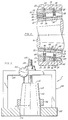
- Fig. 1 is a sectional view in elevation of a mill stand having back-up rolls supported on bearings constructed in accordance with and embodying the present invention;
- Fig. 2 is an end elevational view of the mill stand;
- Fig. 3 is a sectional view of one of the roll neck bearings and the chock in which it is mounted and showing the roll neck in the bearing;
- Fig. 4 is an enlarged fragmentary view showing one of the sections of the roll neck bearing;
- Figs. 5-7 are elevational views of a fixture used in the assembly of the roll neck bearing, and showing sequentially the steps used for selecting roller sets which will distribute radial loads generally uniformly throughout the several sections of the bearing;
- Fig. 8 is a half sectional view showing the chock with the cups and rollers of the bearing passing over the tapered cones during the assembly procedure;
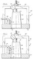
- Fig. 9 is a fragmentary elevational view, partially in section, of the mill stand provided with modified chocks;
- Fig. 10 is a fragmentary end view of the modified mill stand;
- Fig. 11 is an enlarged sectional view taken along line 11-11 of Fig. 9 and showing the channels and caps through which the tie rods extend;
- Fig. 12 is a sectional view taken along line 12-12 of Fig. 11;
- Fig. 13 is a sectional view of a modified bearing; and
- Fig. 14 is a sectional view of the modified bearing, absent its cones and rib rings, fitted around a fixture used to determine the precise sizes to which the rib rings are ground.
- Referring now to the drawings, a mill stand (Figs. 1 & 2) has rolls A, each of which at its ends rotates in a bearing B which in turn is confined within a chock C that fits into a heavy cast iron end frame D mounted securely on a foundation. Actually, the roll A is one of at least two rolls and possibly four, for the typical four-high mill stand has two work rolls between which the metal to be worked passes and in addition a pair of back-up rolls which are larger than the work rolls and prevent the work rolls from deflecting under the spreading force of the metal that is worked by them. As in any mill stand, the chocks C slide relative to the end frames D in which they are located, but are normally held together by large turn down screws T which thread into the frame D and bear against the chocks C for the upper back-up roll A. Hydraulic pressure pistons controlled through a feedback loop may be used to position the chocks C in lieu of the turn down screws T, and are actually more commonly used in today's mill designs.
- The bearing B may be used to support either a work roll or back-up roll or both, although the latter is perhaps the primary application. It classifies as a tapered roller bearing and as such is capable of taking thrust loads as well as the heavy radial loads imparted by the metal which is worked. Being one of a pair of tapered roller bearings, the bearing B may also be adjusted between conditions of end play and preload. In the former a radial clearance exists in the bearing B which detracts from the stability of the roll A, and thus contributes to runout in the roll A. When in preload, the load zone may extend a full 360° within the bearing B, and the axis of the roll A is stabilized. Runout is further reduced by grinding the working surfaces of the roll A of the preloaded bearings B. Indeed, adjusting to preload heretofore has effectively served as a procedure for reducing runout in the spindles of precision machine tools.
- The roll A turns in the bearings B (Fig. 3) about an axis x of rotation which ideally is coincident with its own center axis. The roll A includes a
roll body 2, which may be cylindrical, and aroll neck 4 at each end of thebody 2. Eachroll neck 4 has afillet 6 where it merges into thebody 2 and beyond the fillet 6 atapered surface 8 on which the bearing B is seated. At the end of thetapered surface 8 are twocylindrical surfaces annular groove 14. - Encircling the
fillet 6 is a fillet ring 16 (Fig. 3) having an outwardly directed sealing surface of cylindrical configuration. At the other end of thetapered surface 8, acone thrust ring 18 encircles thecylindrical surface 10, and thering 18 likewise has an outwardly presented sealing surface. The bearing B, which is around thetapered surface 8, is captured between thefillet ring 16 and thecone thrust ring 18. Thegroove 14 that opens out of thesurface 12 contains acircular split ring 20 which serves as a backing for aretaining ring 22 that fits between it and thecone thrust ring 18 and as such encircles thesurface 12. Theretaining ring 22 is provided with anut 24 which threads axially against thethrust ring 18 so that theretaining ring 22 andnut 24 fully occupy the space between thesplit ring 20 and thethrust ring 18 and thus provide a solid backing for the latter. Therings nut 24 are all conventional. - The bearing B, which encircles the
roll neck 4 at thetapered surface 8, has four sections 30 (Fig. 3), each of which is in essence a single row tapered roller bearing that is mounted in the direct configuration, that is with the small diameter ends of its components presented toward the free end of theroll neck 4. Like any single row tapered roller bearing, eachsection 30 includes a cone 32 (Fig. 4), acup 34 surrounding thecone 32, so that an annular space exists between the two, andtapered rollers 36 arranged in a single row or set in the annular space between thecone 32 and thecup 34. In addition, each bearingsection 30 has arib ring 38 located at the end of itscup 34 at which the large ends of thetapered rollers 36 are located so as to maintain therollers 36 in the annular space betweencup 34 andcone 32. Finally, eachsection 30 has acage 39 which maintains the proper circumferential spacing between therollers 36. - The
cone 32 in essence is a tapered sleeve having a tapered bore 40 (Fig. 4) and an outwardly presentedraceway 42 which is likewise tapered. The surface of thebore 40 and theraceway 42 extend to the ends of thecone 32 where thecone 32 has end faces, namely aback face 44 and afront face 46. Thecup 34 has an inwardly presented tapered raceway 48 (Fig. 4) and an outwardly presentedcylindrical surface 50, as well as aback face 52 and a front face 54. - The
rib ring 38 for thebearing section 30 fits snugly against theback face 52 of the cup 34 (Fig. 4) where it is clamped between thatback face 52 and the front face 54 of the precedingcup 34, if there is one. Moreover, therib ring 38 projects radially inwardly beyond the large end of thecup raceway 48 where it is provided with amajor rib 56 that is directed axially, ending at an annular surface against which the large diameter ends of therollers 36 bear. Therib ring 38 for eachsection 30, except the largest, that is the one closest to theroll body 2, also has aminor rib 58 which is directed axially along thecup raceway 48 of thenext section 30. The spacing between themajor rib 56 at the large end of thecup raceway 48 and theminor rib 58 at the small end of theraceway 48, that rib being on theadjacent rib ring 38, is slightly greater than the length of therollers 36. Eachrib ring 38, further, has several radially directedholes 60 arranged at equal intervals around it, and eachhole 60 extends from the outer surface of therib ring 38 to the inner surface out of which it opens. Theholes 60 deliver a fluent lubricant to theroller 36 of thesection 30. - When the roll A revolves, the
rollers 36 for eachsection 30 move along the taperedraceways cone 32 andcup 34 for that section with their large end faces against the face on themajor rib 56 of therib ring 38 for that section. The radial load imposed by the roll A is of course transmitted through therollers 36 to the chock C, and by reason of the tapers in theraceways raceways rollers 36 from the annular space between the tworaceways rib ring 38. - The
major rib 56 of therib ring 38 resists this axially directed expulsion force and thereby maintains the taperedrollers 36 in the correct axial position between theraceways rollers 36 are on apex, meaning that the conical surfaces represented by the tworaceways rollers 36 and theraceways rollers 36 and themajor ribs 56. - Each
roller 36 further has a small bore 62 (Fig. 4) which extends completely through it on its axis. Thecage 39 includes end rings 64 which extend along the large and small end faces of therollers 36 and pins 66 which pass through thebores 62 in therollers 36. As such, thepins 66 restrain therollers 36 circumferentially and thus enable thecage 39 to maintain the proper spacing between therollers 36. - While the
pins 66 maintain the proper circumferential spacing between therollers 36, themajor ribs 56 of the rib rings 38, to a measure, cooperate in this function in that they prevent therollers 36 from skewing excessively. Theminor ribs 58 crowd therollers 36 against their respectivemajor ribs 56 during set up and thus assist in the assembly and adjustment of the bearing B. Therib ring 38 for eachsection 30 provides theminor rib 58 for the preceding or nextlarger section 30. Theminor rib 58 for thesmallest section 30 is carried on itsown end ring 67 which fits against the back face of thecup 34 for that section 30 (Fig. 3). - The four
bearing sections 30 fit in succession over the roll neck 4 (Fig. 3), with thecone 32 of each being seated tightly against the taperedsurface 8 of theroll neck 4 so that no radial clearance exists between any one of thecones 32 and theroll neck 4. Theback face 44 of thelargest cone 32 bears against thefillet ring 16, whereas theback face 44 of each remainingcone 32 abuts thefront face 46 of nextlarger cone 32. The cone thrustring 18 bears against thefront face 46 of thesmallest cone 32, and is urged snugly against that cone by thenut 24 of the retainingring 22. Thus, the fourcones 32 are clamped snugly between thefillet ring 16 and thethrust ring 18 and have no free motion in the axial direction. The fourcones 32 may be considered a single cone for the bearing B and indeed may be united into a single tapered sleeve having oneback face 44 at thefillet ring 16 and onefront face 46 and thethrust ring 18. Not only are therollers 36 of eachsection 30 on apex, but theseveral sections 30 share the same apex, which means the cone raceways 42 lie in a single conical envelope, while the cup raceways 48 lie in another conical envelope of slightly steeper angle, but the two conical envelopes have their respective apexes located at a common point along the axis x. - The chock C constitutes a housing for holding the bearing B and transmitting the loads applied to it to the frame D. It includes a
block 68 having a cylindrical bore 70 (Fig. 3) which receives thecups 34 of the several bearingsections 30. At the end presented toward theroll body 2, thebore 70 opens out of theblock 68, whereas the opposite end of thebore 70 is obstructed by ashoulder 72 against which theend ring 67 for thesmallest bearing section 30 fits, that ring being captured between theshoulder 72 and theback face 52 of thecup 34 for thesmallest section 30. Here theblock 68 is fitted with aseal 74 that bears against the outwardly presented sealing surface on thecone thrust ring 18 to form a fluid barrier which keeps contaminants out of and lubricants within the interior of the bearing B. - The chock C also includes a clamp ring 76 (Fig. 3) which is bolted against the end of the chock C around the unobstructed end of the
bore 70. Thering 76 has anannular rib 78 which projects into thebore 70 and bears against therib ring 38 for the largest of the four bearingsections 30, thus clamping the fourcups 34, the four rib rings 38 and theend ring 67 between it and theshoulder 72 so as to eliminate any clearance or axial free motion. The arrangement is such that theback face 52 of thecup 34 for thesmallest section 30 is against theend ring 67 which in turn is against theshoulder 72, whereas theback face 52 of thecup 34 for each of the remainingsections 30 bears against therib ring 38 for the nextsmaller section 30, forcing those rib rings 38 against thecups 34 with which they cooperate. The front face 54 ofcup 34 for thelargest bearing section 30 bears against therib ring 38 for that section, and thatrib ring 38 in turn bears against theannular rib 78 on theclamp ring 76. In addition to clamping up the fourcups 34, four rib rings 38, and theend ring 67, theclamp ring 76 further carries aseal 80, which contacts the outwardly presented cylindrical surface on thefillet ring 16 to form a fluid barrier which keeps contaminants out of and lubrication within the bearing B. - The
block 68 further contains annular lubricant channels 82 (Figs. 3 & 4) which encircle the three interior rib rings 38, that is, the three rib rings 38 which are captured betweencups 34. The twochannels 82 closest to theshoulder 72 of theblock 68 are connected to a source of pressurized lubricant and, thus, supply lubricant to the interior of the bearing B. Thechannel 82 closest to theclamp ring 76 represents a return duct and is connected to a lubricant sump. Two common lubrication systems used to propel the lubricant into the bearing are an oil mist system and an oil-air system. - The chocks C at each end of the roll A fit into the frame D somewhat loosely so that if unobstructed, they may be moved upwardly or downwardly in the frame D, but the turndown screws T (Figs. 1 & 2) or hydraulic pistons block the chocks C and prevent them from rising above a prescribed elevation. The outboard end of the
block 68 for each chock C on the operator's side of the frame D may have four cylinders 86 (Figs. 1-3) arranged symmetrically about the axis x of rotation, with their own axes parallel to that axis, and eachcylinder 86 contains apiston 88 which projects axially outwardly beyond the end face of theblock 68. Opening into the opposite or inner end of thecylinder 86 is a fluid duct 90 (Fig. 3) which is connected to a source of hydraulic fluid, the pressure of which can be precisely monitored and controlled. The pressurized fluid fills that portion of eachcylinder 86 which is not occupied by thepiston 88 and exerts an axially directed force on thepiston 88. This force exerted by thepistons 88 is resisted by keeper plates 92 (Figs. 1-3) against which thepistons 88 bear, theplates 92 being fixed firmly to the frame D. As a consequence, thepistons 88, with adequate pressure applied to them, urge the entire chock C toward thebody 2 of the roll A, and this causes the taperedraceways sections 30 to seat snugly against therollers 36 of their respective rows. The axial force is transmitted through the roll A to the bearing B at its opposite end and thence into the chock C at that opposite end. That chock bears againstkeeper plates 92 mounted on the other side of the frame D. In short, thepistons 88 bring the bearings B, which support the roll A, into a condition of preload, and thekeeper plates 92 at the two sides of the frame D resist the preload force exerted by thepistons 88. Of course, in this condition no radial clearance exists within those bearings B. The magnitude of the pressure in thecylinders 86 determines the condition of the preload, and that condition remains constant as long as the pressure does not vary, even if the roll A undergoes an axial expansion due to an increase in temperature. Thus, thecylinder 86 andpiston 88 serve to compensate for thermal expansion and contraction, keeping the two bearings B for the roll A in the same condition of preload, irrespective of the length of the roll A. This contrasts with conventional roll neck bearings which have their rollers set alternately in the direct and indirect configurations so that preload cannot be adjusted, except perhaps during initial assembly of the bearing at the factory. Ideally, the magnitude of the preload should be proportional to the magnitude of the separating force applied across theroll body 2 to assure that the number ofrollers 36 under load in anybearing section 30 remains constant irrespective of the separating force applied to theroll body 2. Thecylinders 86 andpistons 88 also accommodate tilting of the chocks C along their respective sides of the frame D, so as to assure more equal distribution of the separating force among the several bearingsections 30. - While the
cylinders 86 andpistons 88 compensate for thermal expansion and contraction and tilting of the chocks C, they are not effective when the roll A and its bearings B and chocks C are out of the frame D. Indeed, unless restrained the bearing B would come apart. The restraint is provided bytie rods 94 which extend between the two chocks C radially beyond themain body 2 of the roll A (Figs. 1 & 3). Thetie rods 94 themselves may be adjusted to bring the bearings B into a condition of preload so as to facilitate grinding themain body 2 of the roll A when the roll A is out of the frame D. - To assemble the bearings B and chocks C about the
roll necks 4 of the roll A so as to have minimal runout at themain body 2 during the operation of the roll A, theroll necks 4 must first be prepared for the bearings B. To this end, the roll A is supported between centers, and thetapered surfaces 8 of itsroll necks 4 are ground to the angle and diameter required to accommodate the fourcones 32. Once thetapered surfaces 8 are properly ground, the roll A is released from the centers and the fillet rings 16 are pressed onto thefillets 6 of the roll necks 4 (Fig. 3). Then thecones 32 for the four bearingsections 30 of each bearing B are forced over eachtapered surface 8 of theroll neck 4 for those bearings. Next, thecone thrust ring 18 is installed over the largecylindrical surface 10 immediately beyond the small end of the taperedsurface 8 and beyond it theexpandable retaining ring 22 andnut 24 are placed around the smallercylindrical surface 12 with thenut 24 backed off to a contracted position. Thenut 24 is moved up against thethrust ring 18 so thegroove 14 is exposed, whereupon thesplit ring 20 is installed in thegroove 14. Once thesplit ring 20 is secured, thenut 24 is turned on thering 22 such that thenut 24 andring 22 expand axially and force thethrust ring 18 against thefront face 46 of thesmallest cone 32. This clamps all fourcones 32 tightly betweenfillet ring 16 and thecone thrust ring 18, and further causes each to seat snugly on the ground taperedsurface 8 of theroll neck 4. The arrangement is such that not one of the fourcones 32 can shift axially or radially on theroll neck 4 around which it fits. - Once the
cones 32 are fitted securely on theirrespective roll necks 4 with a proper interference fit, the roll A is again mounted between centers and additional grinds are made on the exterior of those cones to bring the cone raceways 42 to the proper angle and diameter. Thus, the cone raceways 42 are concentric, their centers being the axis x of rotation for the roll A. Moreover, they are flush, that is to say they jointly define a single conical surface. Indeed, the fourcones 32 could be replaced by a single cone extending between thefillet ring 16 and thecone thrust ring 18. - In the manufacture of the bearings B, it is nearly impossible to hold actual dimensions to nominal values. Some deviation occurs. Deviations from nominal dimensions are not very significant, insofar as the
raceways 42 of thecones 32 are concerned, as long as their tapers match, or are quite close to, the nominal taper. However, deviations from nominal dimensions in theraceways 48 of thecups 34, and the locations of the radial surfaces on the rib rings 38 have a pronounced effect on the ability of the bearing B to distribute loading evenly between the four sets ofrollers 36. As to therollers 36, after grinding they are measured and segregated such thatrollers 36 of like diameter are assembled into the same production sets. Thus,rollers 36 of one production set may all be larger than the nominal roller diameter, whereas the rollers of another production set may be less than the nominal diameter, but no production set of production rollers should have a great variance in the diameter of itsrollers 36. Productionsets having rollers 36 of the proper diameter are selected with a set-up fixture F on which thecups 34,rollers 36, and rib rings 38 may be assembled (Figs. 5-7). - The fixture F includes (Fig. 5) a
frame 100 having a base 102 and abridge 104 located above thebase 102. Directly beneath thebridge 104, thebase 102 is provided with acylindrical bore 106. Projecting upwardly out of thebore 106 of theframe base 102 is adummy cone 108 having a cylindrical lower end 110, which slides freely in thebore 106, and atapered surface 112, which corresponds in taper and diameter to the ground raceways 42 of theseveral cones 32. In other words, thetapered surface 112 of thedummy cone 108 corresponds to the conical envelope formed by the ground raceways 42 of thecones 32. In addition, thedummy cone 108 has aflat end face 116 which is squared off with respect to the axis of thedummy cone 108 and a threadedstud 118 which projects upwardly through thebridge 104 on theframe 100 where it is fitted with anut 120 which is turned down against thebridge 104 to hold thedummy cone 108 in a fixed position with respect to theframe 100. - The
bridge 104 of the frame carries adial indicator 122 which contacts theend face 116 of thedummy cone 108 and senses the distance between that end face and thebridge 104. In a larger sense, theindicator 122 determines the axial position of the taperedsurface 112 on thedummy cone 108 with respect to thebase 102 of theframe 100. - Finally, the fixture F includes a clamp 124 (Figs. 6 & 7) which moves upwardly and downwardly on the
frame 100, that is, parallel to the axis of thedummy cone 108, yet can be secured in any desired position along that axis. - To assemble the four sets of
rollers 36, the fourcups 34 and the three rib rings 38, such that radial loading in the bearing B will be distributed generally uniformly between therollers 36 of the four sets, a ring gage 126 (Fig. 5) is first fitted over thetapered surface 112 of thedummy cone 108, it having an inside taper 128 which corresponds to the taper of the taperedsurface 112. The largest diameter on the taper 128, which is, of course, at the lower end face of thering 126, equals the diameter at which the large diameter end faces for the taperedrollers 36 of a nominal roller set will locate along theraceway 42 of thecone 32 for thefirst bearing section 30. Assuming that therollers 36, thecup 34 and therib ring 38 for thefirst bearing section 30 are all of nominal dimensions, then the large end faces of therollers 36 would locate at a diameter d on thecone raceway 42, and that diameter d would equal the work point diameter d on thetapered surface 112 of thedummy cone 108. - The
nut 120 is turned to shift thedummy cone 108 and ringgage 126 relative to theframe 100, until the gap between the lower face of thering gage 126 and the upper face of the base 102 on theframe 102 equals a predetermined dimension e. That dimension corresponds to the axial space e between the back of anominal end ring 38 and the large ends of a set ofnominal rollers 36 on theraceway 42 of the larger cone 32 (Fig. 3). Thedial indicator 122 is now adjusted so that it registers zero. Thegage ring 126 is removed from thedummy cone 108. - With
dummy cone 108 retracted from thebridge 104 of theframe 100, thelarge rib ring 38 for the bearing B is set upon thebase 102 around thebore 106 with itsmajor rib 56 presented upwardly (Fig. 6). Then, a gage set 130 ofrollers 36 is placed around the taperedsurface 112 of thecone 108 with the large ends of therollers 36 presented downwardly. Being a gage set, therollers 36 of theset 130 are as close to nominal dimensions as possible. Thelarge cup 34 for thefirst bearing section 30 is next placed over the gage set 130 ofrollers 36 and thenext rib ring 38 is placed against itsback face 52. The two end rings 38 with thecup 34 interposed between them are then urged toward the base 106 with theclamp 124. The gage set 130 ofrollers 36 remains somewhat loosely between the two rib rings 38. - Next, the
dummy cone 108 is raised and simultaneously turned to cause the taperedrollers 36 of the gage set 130 to seat against the taperedsurface 112 of thedummy cone 108 and the taperedraceway 48 of thecup 34. The rotation further causes therollers 36 to migrate along the taperedsurface 112 andraceway 48 until their large ends come against themajor rib 56 of thefirst rib ring 38. The reading on thedial indicator 122 is now observed. - If the
dial indicator 122 indicates that thedummy cone 108 is above the location which produced a zero reading, then therollers 36 for the production set used in thefirst bearing section 30 should he larger than therollers 36 of the gage set 130 to acquire a reasonably equal distribution of loads between the production sets ofrollers 36 of allsections 30 when the bearing B is ultimately assembled. On the other hand, if thedial indicator 122 shows that thedummy cone 108 is low, then therollers 36 of the production set must be smaller than therollers 36 of the gage set 130. The object is to select a productionset having rollers 36 which will cause thedummy cone 108 to register zero or as near to zero as possible on thedial indicator 122. - A correllation exists between the axial position of the
dummy cone 108 and the diameter of therollers 36 which are against its taperedsurface 112, and that, of course, depends on the angle of the taper. For a typical mill roll bearing, a 0.0001 inch change in diameter of itsrollers 36 will result in a 0.0024 inch change in the location of thedummy cone 108 along its axis. Of course, thetapered surface 112 of thedummy cone 108 represents the ground raceways 42 of the fourcones 32, and what holds true with respect to a production set ofrollers 36 on thedummy cone 108, likewise applies to a production set on theraceway 42 of thecone 32 for thefirst bearing section 30. - The diameter of the
rollers 36 for the production set of thefirst bearing section 30 having been determined, thedummy cone 108 is retracted and the first gage set 130 ofrollers 36 is removed. Thereupon, a gage set 130 ofrollers 36 for thesecond section 30 is placed loosely around the taperedsurface 112 of the retracteddummy cone 108 and allowed to rest with the large end faces of itsrollers 36 against themajor rib 56 of the second rib ring 38 (Fig. 7). Thecup 34 of thesecond section 30 is lowered over this set and thethird rib ring 38 is placed against theback face 52 of that cup. The twocups 34 and the three rib rings 38 are then held firmly in a stack with theclamp 124, whereupon thedummy cone 108 is again raised and turned to seat therollers 36 of the second gage set. Thedial indicator 122 is observed to determine whether thedummy cone 108 is high or low, and a production set ofrollers 36 is selected having a size which will cause thedial indicator 122 to register zero or near zero if it were substituted for the second gage set 130. - The production sets of
rollers 36 for the third andfourth bearing sections 30 are selected in a like manner. - Once the
rollers 36, rib rings 38, cups 34, and theend ring 68 are all properly set up on thedummy cone 100, they are fitted to theblock 68 of the chock C where a snug fit exists between eachcup 34 and thebore 70 of the block. Theclamp ring 76 is then installed and its machine bolts tightened so that the rib rings 38, thecups 34, and theend ring 67 are all clamped together between theshoulder 72 and theclamp ring 76. Then the chock C with thecups 34,rollers 36, rib rings 38 andend ring 67, all secured within it as transferred to theroll neck 4, it being fitted over thecones 32 until therollers 36 seat against their respective cone raceways 42 (Fig. 8). - At this time the roll A along with its
chocks 4 is transferred to a roll grinder, and with the chocks C urged axially together to place the bearings B in a condition of preload, the roll A is turned while itsroll body 2 is ground. This in-chock grinding eliminates essentially all eccentricity from theroll body 2 so that it turns on the axis x of rotation without runout. Since theseveral sections 30 of each bearing B are stacked they share the axial force that provides the preload, and thus eachsection 30 is in a condition of preload. - The bearings B provide the mill roll A and the mill stand 5 with several very significant advantages not accorded by conventional multirow tapered roller bearings or cylindrical roller bearings. Among those advantages are increased stiffness and the near absence of eccentricity. Since the tapered
rollers 36 and theraceways tapered surfaces 8 andcone raceways 42 before the bearing B is fully assembled, and by the further machining of theroll body 2 after the bearings B are assembled and preloaded. It is thus possible to eliminate essentially all eccentricity from theroll body 2, except for perhaps the eccentricity that results from therollers 36, which is minimal. - Additional stiffness derives from the direct mounting, that is to say the downward taper toward the outboard ends of the
roll necks 4, for the direct mounting reduces the effective bearing spread. - Aside from the stability and stiffness that they afford, the bearings B are easily assembled, and this derives from the flair of the
rollers 36 of the several sets, all outwardly toward the open ends of their respective chocks C (Fig. 6). Thus, the chocks C are easily installed over theroll necks 4. In contrast, cylindrical bearings are manufactured with as little clearance as possible, and this makes assembly difficult and occasionally results in damaged rollers or raceways. - Also, where the
pistons 88 are utilized for preloading the bearings B, it is possible to control the load zone within the bearings B by varying the pressure of the fluid in thehydraulic cylinders 86. Indeed, the load zone is usually extended over 360° through preloading, while in a cylindrical bearing it cannot exceed 180°. Moreover, thecylinders 86 and theirpistons 88 accommodate thermal expansion and contraction of the roll A without changing the condition of preload. - The
rollers 36, which are selected for the several rows, provide a convenient means for distributing the radial loads in a desired manner amongst the several rows ofrollers 36 if that is desired. For example, the metal which is worked tends to deflect the roll A slightly and thereby impose a greater radial load on the inner rows ofrollers 36, that is the rows containing thelargest bearing sections 30, but the rollers of the inner rows can be slightly undersized so that those rows take less loading when the roll A runs without deflection. Then, when the deflection occurs, therollers 36 of the inner rows do not assume any more load than therollers 36 of the outer rows. - The mill roll A and its bearing B may be confined by modified chocks E (Figs. 9 and 10) which are quite similar to the chocks C, except that neither chock E contains
hydraulic cylinders 86 orpistons 88 for preloading the bearing B. In lieu of thecylinders 86, the chocks E have throughchannels 134 and throughbores 136, preferably four in number, arranged symmetrically about the axis x of the rotation for the roll A (Fig. 10). The twochannels 134 are covered by caps 138 (Fig. 10). Eachchannel 134 and itscap 138 receives a thrust washer 140 (Fig. 12) and the same holds true for each bore 137. For eachchannel 134,cap 138 andwasher 140 the chock E on the operator side of the frame D, a correspondingchannel 136,cap 138 andwasher 140 exists in the chock C on the drive side of the frame D, and for eachbore 136 on the operator side acorresponding bore 136 exists on the drive side. Extending through the alignedwashers 140 in the two chocks E aretie rods 142, and, indeed, thetie rods 142 pass completely through thechannels 134 and bores 136 and project beyond the end faces of the chocks E. Here they are provided withthreads 144. - Fitted over the outwardly projecting ends of the
tie rods 142 arespring packs 146, each consisting of several Belleville springs fitted end-to-end. Eachspring pack 146 is captured between thethrust washer 140 of the chock E from which itsrod 142 projects and anotherwasher 148 which is held by anut 150 that is turned down over thethreads 144 on the end of therod 142, thereby compressing the individual springs of thespring pack 146. Thenuts 150 of theseveral rods 142 are adjusted such that the force exerted on the chocks E by the compressed springs of the spring packs 146 induces the desired preload in the bearings B. Coil-type compression springs may be substituted for the Belleville springs of the spring packs 146. - A modified bearing F (Fig. 13) is quite similar to the bearing B and like the bearing D has
cones 32, taperedrollers 36 andcages 39 arranged in foursections 160. However, in lieu of a separately formedcup 34 andrib ring 38, eachsection 160 of the bearing F has acup 162 provided with atapered raceway 164 and amajor rib 166 formed integral with thecup 162 at the large end of itsraceway 164. The outside diameter of therib 166 is less than the outside diameter of the main body for thecup 162 so as to create within thebore 70 of the chock C anannular chamber 168 at the end of thecup 162. In order to deliver oil to the critical inside face of therib 166, thecup 162 hasseveral oil holes 170 which lead obliquely from the offset 168 to the region where the taperedraceway 164 merges into therib 166. Eachcup 162 has abackface 172 and afront face 174, the latter being on therib 166. - In addition, each
section 160 of the bearing F includes arib ring 176 having aflange 178 which lies against theback face 172 of itscup 162 and aminor rib 180 which projects slightly into thecup 162 at the small diameter end of itsraceway 164. The width of theflange 178 controls the proportion of the load taken by thesection 160, and indeed the rib rings 176 are initially machined with theirflanges 178 somewhat thicker than required so that they may be ground down to distribute the loads equally between the foursections 160 or otherwise as may be desired. - To assemble the bearing F, the tapered
rollers 36 and thecup 162 for eachsection 160 are fitted over thedummy cone 108 with the tapered side faces of therollers 36 being against the taperedsurface 112 of the dummy cone 108 (Fig. 14). Thecups 162 are oscillated to insure that therollers 36 within them are oriented correctly with respect to thecup raceways 164 and to further insure that the large end faces of therollers 36 seat against theintegral ribs 166. A dial indicator may be used to verify that eachcup 162 is properly aligned, that is to say that it is square with respect to the axis of thedummy cone 108. - Due to the absence of the rib rings 176, three gaps g (Fig. 14) exist between the four
cups 162. More specifically, a separate gap g exists between theback face 172 of eachcup 162, except thelast cup 162, and thefront face 174 on theintegral rib 166 of thenext cup 162. The gaps g represent the space normally occupied by theflanges 178 of rib rings 176 for the bearing F, and of course theflanges 178 must fit their respective gaps g. To this end, the gaps g are measured and theflanges 178 of the rib rings 176, being initially oversized, are ground to match the dimensions of the gaps g. - Thus, when the bearing F is reassembled with the
cones 32 andrib ring 176, the bearingsections 160 will share the load substantially equally. Of course, the load may be distributed as desired among the several bearingsections 160 by controlling the thickness of theflanges 172. For example, if one desires to decrease the load taken by a bearing section, theflange 172 at theintegral rib 166 for that section is ground slightly thicker than the gap g measured along thedummy cone 108. - While the bearings B or F and the chocks C or E support a mill roll in a mill stand, with minor adaptations, they may be used in other types of rolls, such as calendars for rolling plastics and elastomers. Furthermore, the roll configuration could be extended to include Z-mills, 6-high mills or other mills used for rolling material to a precise thickness.
Claims (16)
- A tapered roller bearing comprising a cone (32) having a plurality of outwardly facing tapered raceways (42, 48), a plurality of bearing cups (34) disposed about the raceways (42) of the cone (32) with each having a single raceway (48) inclined in the same direction as the cone raceway (42) that it surrounds, a row of tapered rollers (36) located within each cup raceway (48) and surrounding that cone raceway (42) opposite that cup raceway (48), with the rollers (36) contacting the cup (48) and cone (42) raceways, characterized in that the cone (32) is formed as a single element or as multiple annular elements (32) placed end to end, the raceways (42) of the cone (32) being of progressively greater diameter along the length of the cone (32) such that each raceway thereof beyond the one having the smallest diameter has at its smaller end a diameter at least as large as the diameter of the larger end of the raceway which precedes it; a major rib (56) located in a fixed position at the end of each cup (34) and arranged to project radially inwardly beyond the large end of the raceway (48) of the cup (34) to provide a surface against which the large ends of the rollers (36) bear; and means (38) for locating the cups (34) with respect to each other.
- A bearing according to claim 1, characterized in that the raceways (42) of the cone (32) define a common conical envelope having its apex and axis on the central axis of the bearing.
- A bearing arrangement as claimed in claim 2, characterized in that the raceway (48) of each of the cups (34) defines a conical envelope having its apex substantially coincident with the apex of said common conical envelope.
- A bearing according to any one of the preceding claims, characterized in that the means for locating the cups with respect to each other comprises rib rings (38) located between the ends of adjacent cups (34).
- A bearing according to claim 4, characterized in that the major ribs (56) are on the rib rings (38).
- A bearing as claimed in any one of claims 1 to 3, characterized in that the major ribs (56) are formed integrally with the cups (34).
- A bearing as claimed in any one of claims 1 to 6, characterized in that the radially inner surface of the cone (32) extends substantially parallel to the raceways (42) of the cone (32).
- A bearing arrangement including a housing (68) in which is located a tapered roller bearing as claimed in claim 4 or claim 5, and means (76) for clamping the cups (34) axially relative to the housing (68).
- A bearing arrangement as claimed in claim 8, characterized in that the bearing is one of two bearings located at opposite ends of a shaft, and in that tie rods (94, 142) interconnect the housings (68) for the two bearings to prevent the housings from separating.
- A bearing arrangement according to claim 9, characterized by springs (146) which are disposed about the tie rods for exerting an axially directed force on the housing.
- A bearing arrangement according to any one of claims 8 to 10, characterized by a fluid operated cylinder (86, 88) for exerting an axially directed force on the housing.
- A bearing arrangement according to any one of claims 8 to 11, characterized by seal means (80) beyond the endmost rows of tapered rollers (36) for maintaining a lubricant in the space between the raceways of the cone and cup, one of which seal means is carried by the clamp means (76).
- A bearing arrangement as claimed in any one of claims 9 to 12 characterized in that the shaft is a mill roll having at each end a roll neck in the form of a stub shaft.
- A method of manufacture of a bearing arrangement as claimed in claim 13, characterized by the steps of installing the bearing cones (32, 32...) on the respective stub shafts (4) with their raceways decreasing in diameter towards the free ends of the shafts, then grinding each of the bearing cones while on the stub shaft so that the raceways of each cone have a common centre coincident with the axial centre of the shaft on which the cone is mounted; installing the housings (68), with the cups (34), rollers (36) and rib rings (38) in place, over the respective bearing cones (32) on the stub shafts and then, while the mill roll is supported by said bearing assemblies, grinding the body part (2) of the roll between the stub shafts so that said body part has its centre along the common axis of the bearing assemblies.
- A method as claimed in claim 14, characterized in that the step of grinding said body part (2) of the roll is carried out while the housings of the two bearing arrangements are urged axially towards each other.
- A method as claimed in claim 14 or claim 15, characterized in that in said step of grinding the raceways of each cone (32), the raceways are ground to define a common conical envelope having its axis and its apex on the axis of rotation of the bearing.
Applications Claiming Priority (2)
| Application Number | Priority Date | Filing Date | Title |
|---|---|---|---|
| US427176 | 1989-10-26 | ||
| US07/427,176 US4938615A (en) | 1989-10-26 | 1989-10-26 | Roll neck bearing |
Publications (2)
| Publication Number | Publication Date |
|---|---|
| EP0425072A1 EP0425072A1 (en) | 1991-05-02 |
| EP0425072B1 true EP0425072B1 (en) | 1994-06-22 |
Family
ID=23693792
Family Applications (1)
| Application Number | Title | Priority Date | Filing Date |
|---|---|---|---|
| EP90305482A Expired - Lifetime EP0425072B1 (en) | 1989-10-26 | 1990-05-21 | Bearing and bearing arrangement |
Country Status (4)
| Country | Link |
|---|---|
| US (1) | US4938615A (en) |
| EP (1) | EP0425072B1 (en) |
| JP (1) | JP2895940B2 (en) |
| DE (1) | DE69010141T2 (en) |
Families Citing this family (20)
| Publication number | Priority date | Publication date | Assignee | Title |
|---|---|---|---|---|
| JP2566197Y2 (en) * | 1992-08-05 | 1998-03-25 | 株式会社明電舎 | Dynamometer device |
| DE4334021C1 (en) * | 1993-10-06 | 1995-04-06 | Achenbach Buschhuetten Gmbh | Device for positioning and locking a chock on a roll neck when installing and removing a set of rolls in or out of a roll stand with rolls |
| US5857396A (en) * | 1995-08-25 | 1999-01-12 | Strouse, Jr.; Joseph M. | Slitting machine |
| US6334713B1 (en) | 1999-03-23 | 2002-01-01 | Roller Bearing Industries, Inc. | Bearing assembly having an improved wear ring liner |
| US6485185B1 (en) | 1999-08-16 | 2002-11-26 | Roller Bearing Industries, Inc. | Bearing seal |
| US6468194B2 (en) | 2000-12-08 | 2002-10-22 | Morgan Construction Company | Sleeve for rolling mill oil film bearing |
| DE10358869A1 (en) * | 2003-12-16 | 2005-07-14 | Sms Demag Ag | Method and device for preloading tapered roller bearings of a rolling mill roll |
| US7578061B2 (en) * | 2004-11-18 | 2009-08-25 | Sms Demag Ag | Method and device for prestressing tapered roller bearings of a rolling mill roller |
| DE102005022205A1 (en) | 2005-05-13 | 2006-11-16 | Schaeffler Kg | Four row tapered roller bearing |
| DE102005043104B4 (en) * | 2005-09-10 | 2015-12-17 | Esa Eppinger Gmbh | Device for lubricating bearing points on machine tools or parts thereof |
| US7866894B2 (en) * | 2006-09-25 | 2011-01-11 | Baldor Electric Company | Hydraulically positioned shaft bearing attachment system and method |
| DE102007014743B4 (en) * | 2007-03-23 | 2008-11-13 | Alexanderwerk Ag | Compacting machine and method for continuous control of roll parallelism in compacting machines |
| US20090034896A1 (en) * | 2007-08-03 | 2009-02-05 | Kenneth Lee Fisher | Bearing retainer |
| EP2459328B1 (en) * | 2009-07-30 | 2014-04-02 | The Timken Company | Method and apparatus for setting rolling element bearings in rolling mills |
| US8696212B2 (en) * | 2012-03-01 | 2014-04-15 | Amsted Rail Company, Inc. | Roller bearing backing ring assembly |
| WO2015142733A1 (en) * | 2014-03-20 | 2015-09-24 | The Timken Company | Mill roll with hollow center shaft for circulating fluid and method for controlling bearing setting in same |
| JP6565454B2 (en) * | 2015-08-05 | 2019-08-28 | 日本精工株式会社 | Combination ball bearing, spindle device, and machine tool |
| DE102017217562A1 (en) | 2017-06-01 | 2018-12-06 | Sms Group Gmbh | Bearing locking device and method for its operation |
| CN110053990B (en) * | 2019-06-03 | 2020-07-17 | 山东方大清洁能源科技有限公司 | Anti-blocking type coal powder high-speed loading and unloading device with automatic loading and unloading function |
| CN112588831A (en) * | 2020-11-25 | 2021-04-02 | 广西柳州钢铁集团有限公司 | Equal-width rolling roller |
Family Cites Families (12)
| Publication number | Priority date | Publication date | Assignee | Title |
|---|---|---|---|---|
| US647270A (en) * | 1900-01-22 | 1900-04-10 | Moline Plow Co | Disk-bearing. |
| US1208428A (en) * | 1914-01-09 | 1916-12-12 | Frank Whitney | Roller bearing. |
| US1984718A (en) * | 1932-05-20 | 1934-12-18 | Skf Svenska Kullagerfab Ab | Method of eliminating eccentricity in the rotation of work spindles for machine tools |
| US2037206A (en) * | 1934-01-02 | 1936-04-14 | Timken Roller Bearing Co | Shaft bearing |
| US2130258A (en) * | 1936-05-25 | 1938-09-13 | Timken Roller Bearing Co | Multiple-row taper roller bearing |
| DE1138011B (en) * | 1961-05-13 | 1962-10-18 | Siemag Siegener Masch Bau | Arrangement for pulling off or pushing on the bearing housing from shaft stubs or onto shaft stubs from winding drums or similar devices |
| US3180016A (en) * | 1961-07-27 | 1965-04-27 | Bantam Bearings Division | Fluid-operated mounting or dismounting rig for tight fitted bearing assemblies and the like |
| US3940193A (en) * | 1973-05-03 | 1976-02-24 | General Motors Corporation | Roller bearing separator |
| US4235485A (en) * | 1978-12-21 | 1980-11-25 | The Timken Company | Unitized multirow tapered roller bearing |
| JPS5939884B2 (en) * | 1979-09-07 | 1984-09-27 | ティーディーケイ株式会社 | Voltage nonlinear resistor ceramic composition and its manufacturing method |
| JPS5740930A (en) * | 1980-08-22 | 1982-03-06 | Mitsubishi Electric Corp | Formation of wiring pattern |
| US4341426A (en) * | 1980-10-22 | 1982-07-27 | The Timken Company | Clamp-up device for roll neck bearings |
-
1989
- 1989-10-26 US US07/427,176 patent/US4938615A/en not_active Expired - Lifetime
-
1990
- 1990-05-21 DE DE69010141T patent/DE69010141T2/en not_active Expired - Fee Related
- 1990-05-21 EP EP90305482A patent/EP0425072B1/en not_active Expired - Lifetime
- 1990-09-14 JP JP2245971A patent/JP2895940B2/en not_active Expired - Fee Related
Also Published As
| Publication number | Publication date |
|---|---|
| DE69010141D1 (en) | 1994-07-28 |
| US4938615A (en) | 1990-07-03 |
| JP2895940B2 (en) | 1999-05-31 |
| EP0425072A1 (en) | 1991-05-02 |
| JPH03140615A (en) | 1991-06-14 |
| DE69010141T2 (en) | 1994-11-17 |
Similar Documents
| Publication | Publication Date | Title |
|---|---|---|
| EP0425072B1 (en) | Bearing and bearing arrangement | |
| JP2527413B2 (en) | Multiple radial bearing | |
| US4085984A (en) | Double row bearing assembly with tapered roller bearings | |
| EP2459328B1 (en) | Method and apparatus for setting rolling element bearings in rolling mills | |
| US4273391A (en) | Device for axial adjustment of a rotatable body | |
| CN111919043B (en) | Assembly tool and method for positioning rolling elements of a bearing assembly during a preload operation | |
| CA2039048A1 (en) | Bearing assembly for a shaft journal | |
| GB2041462A (en) | Unitized multirow tapered roller bearing | |
| US5118206A (en) | Cone bore seal | |
| EP0126607A2 (en) | Cartridge bearing apparatus and method | |
| US6357921B1 (en) | Radial-axial bearing assembly | |
| EP0844409B1 (en) | Bearing assembly | |
| US4615627A (en) | Roller bearing assembly | |
| GB2199621A (en) | Rolling bearings | |
| US3937539A (en) | Bearing assembly having press-fitted thrust ribs | |
| US4714359A (en) | Rolling bearing arrangement, in particular for work rolls in high-speed rolling mills | |
| US6679634B2 (en) | Low maintenance easily changeable bearing | |
| US3830633A (en) | Method and apparatus for adjusting tapered roller bearings and for assembling devices employing such bearings as journals | |
| US5470159A (en) | Cage guide for rolling bearings, in particular for axial cylindrical roller bearings | |
| US3502375A (en) | Bearing assembly | |
| US4092048A (en) | Roll supports with hydrostatic and roller bearings | |
| US4910846A (en) | Method of adjusting the axial play between a journalled shaft and a surrounding bearing casing | |
| US7578061B2 (en) | Method and device for prestressing tapered roller bearings of a rolling mill roller | |
| US3580648A (en) | Roll and antifriction bearing assembly | |
| US6450693B1 (en) | Bearing arrangement for a shaft supporting a rotating tool |
Legal Events
| Date | Code | Title | Description |
|---|---|---|---|
| PUAI | Public reference made under article 153(3) epc to a published international application that has entered the european phase |
Free format text: ORIGINAL CODE: 0009012 |
|
| AK | Designated contracting states |
Kind code of ref document: A1 Designated state(s): DE FR GB SE |
|
| 17P | Request for examination filed |
Effective date: 19910806 |
|
| 17Q | First examination report despatched |
Effective date: 19921015 |
|
| GRAA | (expected) grant |
Free format text: ORIGINAL CODE: 0009210 |
|
| AK | Designated contracting states |
Kind code of ref document: B1 Designated state(s): DE FR GB SE |
|
| PG25 | Lapsed in a contracting state [announced via postgrant information from national office to epo] |
Ref country code: FR Effective date: 19940622 |
|
| REF | Corresponds to: |
Ref document number: 69010141 Country of ref document: DE Date of ref document: 19940728 |
|
| EN | Fr: translation not filed | ||
| EAL | Se: european patent in force in sweden |
Ref document number: 90305482.3 |
|
| PLBE | No opposition filed within time limit |
Free format text: ORIGINAL CODE: 0009261 |
|
| STAA | Information on the status of an ep patent application or granted ep patent |
Free format text: STATUS: NO OPPOSITION FILED WITHIN TIME LIMIT |
|
| 26N | No opposition filed | ||
| REG | Reference to a national code |
Ref country code: GB Ref legal event code: IF02 |
|
| PGFP | Annual fee paid to national office [announced via postgrant information from national office to epo] |
Ref country code: DE Payment date: 20060419 Year of fee payment: 17 |
|
| PG25 | Lapsed in a contracting state [announced via postgrant information from national office to epo] |
Ref country code: DE Free format text: LAPSE BECAUSE OF NON-PAYMENT OF DUE FEES Effective date: 20071201 |
|
| PGFP | Annual fee paid to national office [announced via postgrant information from national office to epo] |
Ref country code: SE Payment date: 20080421 Year of fee payment: 19 |
|
| PGFP | Annual fee paid to national office [announced via postgrant information from national office to epo] |
Ref country code: GB Payment date: 20090522 Year of fee payment: 20 |
|
| PG25 | Lapsed in a contracting state [announced via postgrant information from national office to epo] |
Ref country code: GB Free format text: LAPSE BECAUSE OF EXPIRATION OF PROTECTION Effective date: 20100520 |
|
| PG25 | Lapsed in a contracting state [announced via postgrant information from national office to epo] |
Ref country code: SE Free format text: LAPSE BECAUSE OF NON-PAYMENT OF DUE FEES Effective date: 20090522 |