EP2458599B1 - Magnetic shield for current transformer in electronic watt-hour meter - Google Patents
Magnetic shield for current transformer in electronic watt-hour meter Download PDFInfo
- Publication number
- EP2458599B1 EP2458599B1 EP11189418.4A EP11189418A EP2458599B1 EP 2458599 B1 EP2458599 B1 EP 2458599B1 EP 11189418 A EP11189418 A EP 11189418A EP 2458599 B1 EP2458599 B1 EP 2458599B1
- Authority
- EP
- European Patent Office
- Prior art keywords
- shield
- current transformer
- hour meter
- electronic watt
- gap
- Prior art date
- Legal status (The legal status is an assumption and is not a legal conclusion. Google has not performed a legal analysis and makes no representation as to the accuracy of the status listed.)
- Not-in-force
Links
Images


Classifications
-
- H—ELECTRICITY
- H01—ELECTRIC ELEMENTS
- H01F—MAGNETS; INDUCTANCES; TRANSFORMERS; SELECTION OF MATERIALS FOR THEIR MAGNETIC PROPERTIES
- H01F27/00—Details of transformers or inductances, in general
- H01F27/34—Special means for preventing or reducing unwanted electric or magnetic effects, e.g. no-load losses, reactive currents, harmonics, oscillations, leakage fields
- H01F27/36—Electric or magnetic shields or screens
- H01F27/366—Electric or magnetic shields or screens made of ferromagnetic material
-
- H—ELECTRICITY
- H01—ELECTRIC ELEMENTS
- H01F—MAGNETS; INDUCTANCES; TRANSFORMERS; SELECTION OF MATERIALS FOR THEIR MAGNETIC PROPERTIES
- H01F38/00—Adaptations of transformers or inductances for specific applications or functions
- H01F38/20—Instruments transformers
- H01F38/22—Instruments transformers for single phase ac
- H01F38/28—Current transformers
- H01F38/30—Constructions
Definitions
- This invention relates generally to electronic watt-hour meters and more particularly to a shield for a current transformer in an electronic watt-hour meter.
- Electronic watt-hour meter 102 is used to measure usage of electricity.
- Electronic watt-hour meter 102 may include a meter base 103 and at least one current transformer 104 with a potential link 106 running through each current transformer 104.
- Other components included in electronic watt-hour meter 102 may include, for example, a surge suppressor 105, a current transformer cable 107, and metrology circuitry bracket 109.
- a current is measured by a metrology circuitry (not shown) in electronic watt-hour meter 102 and used in the calculation of energy usage.
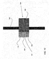
- FIG. 3 a perspective view, of a known current transformer 104 and known potential link 106 are shown.
- a potential link current flow 122 (shown by arrow) through potential link 106 may produce a current transformer magnetic field 116 in current transformer 104.
- Current transformer magnetic field 116 may moves circularly through a ferrite core (not shown) of current transformer.
- Current transformer magnetic field 116 may cause a current transformer current flow 117 in current transformer 104 directly proportional to the number of windings 119 in current transformer 104 and potential link current flow 122.
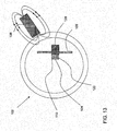
- FIG. 4 a simplified top view of electronic watt-hour meter 102 is shown for illustrative purpose.
- current transformer 104 is affected by an external magnet magnetic field 115 from external magnet 108.
- External magnet 108 may saturate a current transformer 104, thereby reducing its ability to accurately induce a proportional current in the windings (not shown) of current transformer 104.
- This reduction in performance results in a lower value of current flowing in the current transformer 104 and an incorrect electricity usage calculation.
- Use of an external magnet 108 for this purpose may result in theft of electricity. Shielding of the current transformer 104 may result in reducing the effect of the external magnet 108 on the current transformer 104.
- US 5,828,282 discloses a magnetic shield generally corresponding to the preamble of claim 1 herein, with the magnetic shield disclosed in the form of a cup portion and a cap portion, both of which are C-shaped.
- GB 542,861 discloses a power transformer or choke for use in conjunction with a transmission line.
- US 3,366,907 discloses a core-form transformer having high reactance and high leakage flux.
- EP 0,556,099 A1 discloses a current sensor in use with a magnetic screen.
- US 5,079,462 discloses a brushless electrical power generator having reduced harmonics.
- US 4,030,057 discloses an inductive voltage transformer.
- the invention resides in an electronic watt-hour met as defined in present claim 1.
- First shield 110 is illustrated closer to external magnet 108 than second shield 120.
- First shield 110 or second shield 120 may be thicker than the other depending upon which of first shield 110 or second shield 120 is closest to anticipated location of external magnet 108.
- First shield 110 and/or second shield 120 may be placed on current transformer 104 during manufacture of current transformer 104 or electronic watt-hour meter or both. Alternatively, first shield 110 and/or second shield 120 may be placed on current transformer 104 subsequent to manufacture of electronic watt-hour meter.
- current transformer 104 may be substantially torodial in shape and potential link 106 may be rod-like in shape.
- first shield 110 or second shield 120 may substantially protect current transformer 104 from external magnet magnetic field 115 of approximately 5000 gauss or less when external magnet 108 is located, for example, approximately 1.27 centimeters (0.5 inches) or more away from current transformer 104.
- First shield 110 may include a substantially disc shape body 111 having an edge 112.
- Current transformer 104 may be torodial in shape.
- Substantially disc shape body 111 may physically cover current transformer 104.
- First shield 110 may include other shapes, e.g. square, triangle, or other polygonal shapes.
- First shield 110 may include an aperture 114 which may extend through approximately a center of body 111.
- First shield 110 and second shield 120 may be placed on current transformer 104 by placing potential link 106 through aperture 114.
- First shield 110 may include a substantially magnetically permeable and conductive metal.
- Magnetic permeability is the ability of a material to support the formation of a magnetic field within itself. It is the degree of magnetization that a material obtains in response to an applied magnetic field.
- Substantially magnetically permeable and conductive metal may include low carbon steel such as cold rolled steel and/or hot rolled steel. Low carbon steel may include a range of 0.05 percent to 0.26 percent carbon content such as American Iron and Steel Institute (AISI) 1005 to AISI 1026 steel.
- a thickness 113 of body 111 may range from, for example, approximately 0.15 centimeters to 0.64 centimeters (approximately 0.060 inches to 0.250 inches).
- First shield 210 includes a gap 216 extending from an edge 212 to aperture 214.
- Gap 216 includes two substantially parallel straight sides 218 extending from edge 212 to aperture 214 resulting in a generally linear gap 216.
- a current flowing through first shield 110 may produce energy losses in the form of heat and reduce the efficiency of electronic watt-hour meter 102.
- Gap 216 may interrupt the current flowing through the first shield 210 reducing energy losses.
- FIG. 8 an embodiment of a first shield 210 in accordance with the invention is shown that includes irregularities in sides 218.
- sides 218 are not straight for the purpose of accommodating components in electronic watt-hour meter 102, e.g. they may include curving sides, notches, etc.
- a gap 316 may include two non-parallel straight sides 318 extending from an edge 312 to an aperture 314 resulting in a substantially pie-shaped gap 316.
- sides 318 may not be straight.
- first shield 110 may be placed on a first side 111 of current transformer 104.
- Second shield 120 may be placed on a second side 121 of current transformer 104.
- Second side 121 may be substantially parallel to first side 111.
- Aperture 114 accommodates potential link 106 extending through current transformer 104.
- Aperture 114 is illustrated as substantially circular.
- aperture 114 may be any shape that accommodates potential link 106.
- Gap 116 may be used to accommodate components within electronic watt-hour meter, e.g., metrology circuitry (not shown) and metrology circuitry bracket 109.
- Gap 116, 216 ( FIG. 7-9 ) in first shield 110 and/or second shield 120 may be oriented away from the anticipated location of external magnet 108. Alternatively, gap 116 may be sufficiently wide to slide first shield 110 (and second shield 120) over potential link 106.
- Third shield 128 may include a substantially curvilinear planar shape.
- third shield 128 has a slotted tubular shape so as to be 'C' shaped in cross-section. Variants of this shape may be possible, e.g. closed tubular shape and half tubular shape.
- Two ends 132 of third shield 128 may create a third shield gap 130.
- Third shield 128 may include the same substantially magnetically permeable and conductive metal as first shield 110, and may feature the same thickness 113 and protection of current transformer 104 from magnetic field of external magnet 108 as described herein for first shield 110.
- first shield 110 may be placed on a third side 129, e.g., an outer periphery, of current transformer 104.
- Third shield 128 may be connected with at least one of first shield 110 or second shield 120.
- first shield 110, second shield 120, and third shield 128 may form a substantial enclosure of current transformer 104
- first shield 110 a perspective view of one embodiment of first shield 110, second shield 120, and third shield 128 in electronic watt-hour meter in accordance with the invention is shown.
- Third shield 128 may be located on current transformer 104 in substantial proximity to the anticipated location of external magnet 108.
Description
- This invention relates generally to electronic watt-hour meters and more particularly to a shield for a current transformer in an electronic watt-hour meter.
- Referring to
FIG. 1 , a top view, andFIG. 2 , a perspective view, of a known electronic watt-hour meter 102 are shown. Electronic watt-hour meter 102 is used to measure usage of electricity. Electronic watt-hour meter 102 may include ameter base 103 and at least onecurrent transformer 104 with apotential link 106 running through eachcurrent transformer 104. Other components included in electronic watt-hour meter 102 may include, for example, asurge suppressor 105, acurrent transformer cable 107, andmetrology circuitry bracket 109. A current is measured by a metrology circuitry (not shown) in electronic watt-hour meter 102 and used in the calculation of energy usage. - Referring to
FIG. 3 , a perspective view, of a knowncurrent transformer 104 and knownpotential link 106 are shown. A potential link current flow 122 (shown by arrow) throughpotential link 106 may produce a current transformermagnetic field 116 incurrent transformer 104. Current transformermagnetic field 116 may moves circularly through a ferrite core (not shown) of current transformer. Current transformermagnetic field 116 may cause a current transformercurrent flow 117 incurrent transformer 104 directly proportional to the number ofwindings 119 incurrent transformer 104 and potential linkcurrent flow 122. - Referring to
FIG. 4 , a simplified top view of electronic watt-hour meter 102 is shown for illustrative purpose. If anexternal magnet 108 is placed in proximity tocurrent transformer 104, thencurrent transformer 104 is affected by an external magnetmagnetic field 115 fromexternal magnet 108.External magnet 108 may saturate acurrent transformer 104, thereby reducing its ability to accurately induce a proportional current in the windings (not shown) ofcurrent transformer 104. This reduction in performance results in a lower value of current flowing in thecurrent transformer 104 and an incorrect electricity usage calculation. Use of anexternal magnet 108 for this purpose may result in theft of electricity. Shielding of thecurrent transformer 104 may result in reducing the effect of theexternal magnet 108 on thecurrent transformer 104. -
US 5,828,282 discloses a magnetic shield generally corresponding to the preamble of claim 1 herein, with the magnetic shield disclosed in the form of a cup portion and a cap portion, both of which are C-shaped.GB 542,861 US 3,366,907 discloses a core-form transformer having high reactance and high leakage flux.EP 0,556,099 A1 discloses a current sensor in use with a magnetic screen.US 5,079,462 discloses a brushless electrical power generator having reduced harmonics.US 4,030,057 discloses an inductive voltage transformer. - The invention resides in an electronic watt-hour met as defined in present claim 1.
- Embodiments of the present invention will now be described, by way of example only, with reference to the accompanying drawings in which:
-
FIG. 1 shows a top view of a known electronic watt-hour meter. -
FIG. 2 shows a perspective view of a known electronic watt-hour meter. -
FIG. 3 shows a perspective view of a known current transformer and a known potential link. -
FIG. 4 shows a simplified top view of a known electronic watt-hour meter. -
FIG. 5 shows a top view of one embodiment of an electronic watt-hour meter including a first shield and a second shield in accordance with the invention. -
FIG. 6 shows a perspective view of one embodiment of a first shield that does not form part of the present invention. -
FIG. 7 shows a perspective view of one embodiment of a first shield in accordance with the invention. -
FIG. 8 shows a perspective view of one embodiment of a first shield in accordance with the invention. -
FIG. 9 shows a perspective view of one embodiment of a first shield that does not form part of the present invention. -
FIG. 10 shows a side view of one embodiment of a first shield and a second shield for a current transformer in accordance with the invention. -
FIG. 11 shows a perspective view of one embodiment of a third shield in accordance with the invention. -
FIG. 12 shows a top view of one embodiment of a first shield, a second shield, and a third shield for a current transformer in accordance with the invention. -
FIG. 13 shows a top view of one embodiment of electronic watt-hour meter including a first shield, a second shield, and a third shield for a current transformer in accordance with the invention. - It is noted that the drawings of the invention are not to scale. The drawings are intended to depict only typical aspects of the invention, and therefore should not be considered as limiting the scope of the invention. In the drawings, like numbering represents like elements between the drawings.
- Referring to
FIG. 5 , a top view of one embodiment of electronic watt-hour meter including afirst shield 110 and similarly structuredsecond shield 120 in accordance with the invention is shown.First shield 110 is illustrated closer toexternal magnet 108 thansecond shield 120.First shield 110 orsecond shield 120 may be thicker than the other depending upon which offirst shield 110 orsecond shield 120 is closest to anticipated location ofexternal magnet 108.First shield 110 and/orsecond shield 120 may be placed oncurrent transformer 104 during manufacture ofcurrent transformer 104 or electronic watt-hour meter or both. Alternatively,first shield 110 and/orsecond shield 120 may be placed oncurrent transformer 104 subsequent to manufacture of electronic watt-hour meter. In one embodiment of the invention,current transformer 104 may be substantially torodial in shape andpotential link 106 may be rod-like in shape. In one embodiment,first shield 110 orsecond shield 120 may substantially protectcurrent transformer 104 from external magnetmagnetic field 115 of approximately 5000 gauss or less whenexternal magnet 108 is located, for example, approximately 1.27 centimeters (0.5 inches) or more away fromcurrent transformer 104. - Referring to
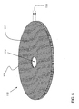
FIG. 6 , a perspective view of one embodiment of afirst shield 110 that does not form part of the present invention is shown.First shield 110 may include a substantiallydisc shape body 111 having anedge 112.Current transformer 104 may be torodial in shape. Substantiallydisc shape body 111 may physically covercurrent transformer 104.First shield 110 may include other shapes, e.g. square, triangle, or other polygonal shapes.First shield 110 may include anaperture 114 which may extend through approximately a center ofbody 111.First shield 110 andsecond shield 120 may be placed oncurrent transformer 104 by placingpotential link 106 throughaperture 114. -
First shield 110 may include a substantially magnetically permeable and conductive metal. Magnetic permeability is the ability of a material to support the formation of a magnetic field within itself. It is the degree of magnetization that a material obtains in response to an applied magnetic field. Substantially magnetically permeable and conductive metal may include low carbon steel such as cold rolled steel and/or hot rolled steel. Low carbon steel may include a range of 0.05 percent to 0.26 percent carbon content such as American Iron and Steel Institute (AISI) 1005 to AISI 1026 steel. Athickness 113 ofbody 111 may range from, for example, approximately 0.15 centimeters to 0.64 centimeters (approximately 0.060 inches to 0.250 inches). - Referring to
FIG. 7 , a perspective view of another embodiment of afirst shield 210 that does not form part of the present invention is shown.First shield 210 includes agap 216 extending from anedge 212 toaperture 214.Gap 216 includes two substantially parallelstraight sides 218 extending fromedge 212 toaperture 214 resulting in a generallylinear gap 216. A current flowing through first shield 110 (without a gap) may produce energy losses in the form of heat and reduce the efficiency of electronic watt-hour meter 102.Gap 216 may interrupt the current flowing through thefirst shield 210 reducing energy losses. Referring toFIG. 8 , an embodiment of afirst shield 210 in accordance with the invention is shown that includes irregularities insides 218. For example, sides 218 are not straight for the purpose of accommodating components in electronic watt-hour meter 102, e.g. they may include curving sides, notches, etc. - Referring to
FIG. 9 , a perspective view of another embodiment offirst shield 310 that does not form part of the present invention is shown. In this case, agap 316 may include two non-parallelstraight sides 318 extending from anedge 312 to anaperture 314 resulting in a substantially pie-shapedgap 316. Similarly to the embodiment shown inFIG. 8 ,sides 318 may not be straight. - Referring to
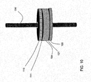
FIG. 10 , a perspective view of one embodiment of afirst shield second shield 120, similarly structured tofirst shield 110, forcurrent transformer 104 in accordance with the invention is shown.First shield 110 may be placed on afirst side 111 ofcurrent transformer 104.Second shield 120 may be placed on asecond side 121 ofcurrent transformer 104.Second side 121 may be substantially parallel tofirst side 111.Aperture 114 accommodatespotential link 106 extending throughcurrent transformer 104.Aperture 114 is illustrated as substantially circular. A person skilled in the art will readily recognize thataperture 114 may be any shape that accommodatespotential link 106.Gap 116 may be used to accommodate components within electronic watt-hour meter, e.g., metrology circuitry (not shown) andmetrology circuitry bracket 109. -
Gap 116, 216 (FIG. 7-9 ) infirst shield 110 and/orsecond shield 120 may be oriented away from the anticipated location ofexternal magnet 108. Alternatively,gap 116 may be sufficiently wide to slide first shield 110 (and second shield 120) overpotential link 106. - Referring to
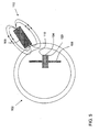
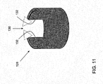
FIG. 11 , a perspective view of one embodiment of athird shield 128 in accordance with the invention is shown.Third shield 128 may include a substantially curvilinear planar shape. In one example shown,third shield 128 has a slotted tubular shape so as to be 'C' shaped in cross-section. Variants of this shape may be possible, e.g. closed tubular shape and half tubular shape. Two ends 132 ofthird shield 128 may create athird shield gap 130.Third shield 128 may include the same substantially magnetically permeable and conductive metal asfirst shield 110, and may feature thesame thickness 113 and protection ofcurrent transformer 104 from magnetic field ofexternal magnet 108 as described herein forfirst shield 110. - Referring to
FIG. 12 , a perspective view of one embodiment offirst shield 110,second shield 120, and athird shield 128 forcurrent transformer 104 in accordance with the invention is shown.Third shield 128 may be placed on athird side 129, e.g., an outer periphery, ofcurrent transformer 104.Third shield 128 may be connected with at least one offirst shield 110 orsecond shield 120. Collectively,first shield 110,second shield 120, andthird shield 128 may form a substantial enclosure ofcurrent transformer 104 - Referring to
FIG. 13 , a perspective view of one embodiment offirst shield 110,second shield 120, andthird shield 128 in electronic watt-hour meter in accordance with the invention is shown.Third shield 128 may be located oncurrent transformer 104 in substantial proximity to the anticipated location ofexternal magnet 108. - The terminology used herein is for the purpose of describing particular embodiments only and is not intended to be limiting of the disclosure. As used herein, the singular forms "a", "an" and "the" are intended to include the plural forms as well, unless the context clearly indicates otherwise. It will be further understood that the terms "comprises" and/or "comprising," when used in this specification, specify the presence of stated features, integers, steps, operations, elements, and/or components, but do not preclude the presence or addition of one or more other features, integers, steps, operations, elements, components, and/or groups thereof.
- The scope of the invention is only defined by the appended claims and any example not being an embodiment of the invention thus defined shall be regarded only for illustrating purposes.
Claims (8)
- An electronic watt-hour meter (102), comprising:a current transformer (104) operatively coupled to the electronic watt-hour meter (102);a potential link (106) extending through the transformer (104);a first shield (110) on a first side (111) of the current transformer (104); anda second shield (120) on a second side (121) of the current transformer (104), wherein the second side (121) is parallel to the first side (111);wherein each of the first and second shields (110, 120) comprisea disc shape body (111), the body (111) including a magnetically permeable and conductive metal;an aperture (114,214,314) through a center of the body (111); anda gap (216,316) in the body, the gap (216, 316) defined by two sides (218) extending from the edge (212, 312) to the aperture (114, 214, 314), and characterized in that the two sides (218) comprise irregularities such that the sides (218) are non-straight.
- The electronic watt-hour meter (102) of claim 1, wherein the substantially magnetically permeable and conductive metal includes a low carbon steel.
- The electronic watt-hour meter (102) of claim 2, wherein the low carbon steel includes less than 0.26 percent carbon content.
- The electronic watt-hour meter (102) of any of claims 1 to 3, further comprising:a third shield (128) on a portion of a third side (129) of the current transformer (104), wherein the third shield (128) is perpendicular to the first (110) and second shields (120); andwherein the third shield (128) includes a magnetically permeable and conductive metal.
- The electronic watt-hour meter (102) of claim 4, wherein the third shield (128) as a curvilinear planar shape.
- The electronic watt-hour meter (102) of any preceding claim, wherein the current transformer (104) is torodial in shape.
- The electronic watt-hour meter (102) of any preceding claim, wherein one of the first shield (110) and the second shield (120) is thicker than the other of the first shield (110) and the second shield (120).
- The electronic watt-hour meter (102) of any preceding claim, wherein the potential link (106) is rod-like in shape.
Applications Claiming Priority (1)
| Application Number | Priority Date | Filing Date | Title |
|---|---|---|---|
| US12/953,713 US8664935B2 (en) | 2010-11-24 | 2010-11-24 | Magnetic shield for current transformer in electronic watt-hour meter |
Publications (2)
| Publication Number | Publication Date |
|---|---|
| EP2458599A1 EP2458599A1 (en) | 2012-05-30 |
| EP2458599B1 true EP2458599B1 (en) | 2014-07-23 |
Family
ID=45062954
Family Applications (1)
| Application Number | Title | Priority Date | Filing Date |
|---|---|---|---|
| EP11189418.4A Not-in-force EP2458599B1 (en) | 2010-11-24 | 2011-11-16 | Magnetic shield for current transformer in electronic watt-hour meter |
Country Status (5)
| Country | Link |
|---|---|
| US (1) | US8664935B2 (en) |
| EP (1) | EP2458599B1 (en) |
| JP (1) | JP2012112947A (en) |
| CN (1) | CN102479609B (en) |
| ES (1) | ES2496416T3 (en) |
Families Citing this family (4)
| Publication number | Priority date | Publication date | Assignee | Title |
|---|---|---|---|---|
| GB2522068B (en) * | 2014-01-14 | 2016-10-19 | Thales Holdings Uk Plc | Electric field screening |
| EP2996121A1 (en) | 2014-09-09 | 2016-03-16 | Core Elektronik Ticaret ve Sanayi Ltd. Sti. | Improved current transformer shield for an electronic watt-hour meter |
| KR101966749B1 (en) * | 2015-12-11 | 2019-04-08 | 주식회사 아모그린텍 | Current transformer with magnetic shielding |
| JP6132043B1 (en) | 2016-02-23 | 2017-05-24 | オムロン株式会社 | Power switchgear |
Family Cites Families (29)
| Publication number | Priority date | Publication date | Assignee | Title |
|---|---|---|---|---|
| GB542861A (en) | 1940-12-02 | 1942-01-29 | Ferranti Ltd | Improvements in or relating to electrical highly-inductive apparatus such as power transformers and chokes |
| GB846362A (en) | 1958-05-24 | 1960-08-31 | Cornigliano Societa Per Azioni | Improvements in or relating to thin ferro-magnetic sheet of low coercive force and high permeability |
| US3366907A (en) | 1965-10-22 | 1968-01-30 | Westinghouse Electric Corp | Core-form transformer pressure ring wound from magnetic material |
| DE2348397B2 (en) | 1973-09-24 | 1979-01-11 | Siemens Ag, 1000 Berlin Und 8000 Muenchen | Inductive voltage converter |
| JPS50125034U (en) * | 1974-03-28 | 1975-10-14 | ||
| US4295112A (en) | 1978-08-30 | 1981-10-13 | Mitsubishi Denki Kabushiki Kaisha | Residual current transformer |
| US4504787A (en) * | 1982-04-05 | 1985-03-12 | Honeywell Inc. | Electronic watthour meter |
| US4760333A (en) | 1984-12-13 | 1988-07-26 | Kanto Seiki Co., Ltd. | Crossed coil meter having concentrically wound magnetic shield |
| US4646045A (en) | 1985-03-25 | 1987-02-24 | General Electric Company | Aperture sized disc shaped end caps of a ferromagnetic shield for magnetic resonance magnets |
| JPH0611903B2 (en) * | 1989-10-19 | 1994-02-16 | 住友金属工業株式会社 | Magnetic steel sheet for magnetic shield and manufacturing method thereof |
| US5079462A (en) | 1990-02-27 | 1992-01-07 | Sundstrand Corporation | Brushless electrical power generator with reduced harmonics |
| FR2687477B1 (en) | 1992-02-14 | 1996-06-07 | Abb Petercem | CURRENT SENSOR. |
| JPH06302451A (en) | 1993-04-15 | 1994-10-28 | Seiko Epson Corp | Manufacture of rare-earth permanent magnet |
| US5853300A (en) * | 1994-03-22 | 1998-12-29 | Ekstrom Industries, Inc. | Watthour socket adapter with improved electrical connections |
| US5486755A (en) | 1994-12-27 | 1996-01-23 | General Electric Company | Electronic meter having anti-tampering magnetic shield |
| JPH1022149A (en) * | 1996-06-28 | 1998-01-23 | Tokin Corp | Zero-phase current transformer |
| US5828282A (en) | 1996-12-13 | 1998-10-27 | General Electric Company | Apparatus and method for shielding a toroidal current sensor |
| US5926014A (en) | 1997-03-17 | 1999-07-20 | General Electric Company | Magnetic shield for plastic molded electricity meter frames |
| DE10003638A1 (en) * | 2000-01-28 | 2001-08-09 | Vacuumschmelze Gmbh | Compensation current sensor |
| US6605937B2 (en) | 2001-06-01 | 2003-08-12 | General Electric Company | Modular meter with base barrier |
| US7267729B2 (en) | 2003-12-18 | 2007-09-11 | Kobe Steel, Ltd. | Soft magnetic low-carbon steel excellent in machinability and magnetic characteristic, method of manufacturing the same and method of manufacturing soft magnetic low-carbon part |
| DE202004000642U1 (en) | 2004-01-16 | 2004-03-18 | Vogt Electronic Aktiengesellschaft | Electromagnetically screened inductive device has a wound ring core within a screening ring between base and flange |
| US7265532B2 (en) | 2004-06-02 | 2007-09-04 | General Electric Company | Electronic electricity meter and method of assembly |
| JP5069978B2 (en) * | 2007-08-31 | 2012-11-07 | 株式会社ダイヘン | Printed circuit board for current / voltage detection and current / voltage detector |
| JP4965402B2 (en) * | 2007-09-27 | 2012-07-04 | パナソニック株式会社 | Current sensor |
| KR100965818B1 (en) * | 2008-05-13 | 2010-06-24 | 태화트랜스 주식회사 | Clamp-type current sensor with a rogowski coil |
| JP5332374B2 (en) * | 2008-07-25 | 2013-11-06 | サンケン電気株式会社 | Semiconductor device |
| US8401469B2 (en) | 2008-09-26 | 2013-03-19 | Hewlett-Packard Development Company, L.P. | Shield for use with a computing device that receives an inductive signal transmission |
| CN201497772U (en) * | 2009-05-31 | 2010-06-02 | 潘兴华 | Star-shaped current sensor structure used for metering gauge |
-
2010
- 2010-11-24 US US12/953,713 patent/US8664935B2/en not_active Expired - Fee Related
-
2011
- 2011-11-16 ES ES11189418.4T patent/ES2496416T3/en active Active
- 2011-11-16 EP EP11189418.4A patent/EP2458599B1/en not_active Not-in-force
- 2011-11-18 JP JP2011252144A patent/JP2012112947A/en active Pending
- 2011-11-24 CN CN201110414347.7A patent/CN102479609B/en not_active Expired - Fee Related
Also Published As
| Publication number | Publication date |
|---|---|
| JP2012112947A (en) | 2012-06-14 |
| EP2458599A1 (en) | 2012-05-30 |
| ES2496416T3 (en) | 2014-09-19 |
| US20120126787A1 (en) | 2012-05-24 |
| CN102479609A (en) | 2012-05-30 |
| CN102479609B (en) | 2016-12-07 |
| US8664935B2 (en) | 2014-03-04 |
Similar Documents
| Publication | Publication Date | Title |
|---|---|---|
| EP2458599B1 (en) | Magnetic shield for current transformer in electronic watt-hour meter | |
| WO2002025677A3 (en) | Planar inductive element | |
| US20170278606A1 (en) | Magnetic circuit component | |
| Lee et al. | Effective combination of soft magnetic materials for magnetic shielding | |
| US10895610B2 (en) | Measuring arrangement for detecting a magnetic unidirectional flux in the core of a transformer | |
| JP6179160B2 (en) | Wireless power transmission equipment | |
| JP2016152248A (en) | Three-phase five-leg iron core and stationary electromagnetic apparatus | |
| CN105157767A (en) | Electromagnetic flow transducer | |
| CN201421774Y (en) | Electromagnetic shielding device of mutual inductor | |
| CN106018912A (en) | High-precision universal alternative and direct current measuring device | |
| CN204963918U (en) | Electromagnetic flow sensor | |
| JP6857494B2 (en) | Static induction electric device | |
| CN2909477Y (en) | Current transformer | |
| Chen et al. | Measurement research on magnetic properties of electrical sheet steel under different temperature, harmonic and dc bias | |
| JP4354898B2 (en) | Magnetic shield structure for AC power single wire cable | |
| RU2543981C1 (en) | Adjustable arc compression coil | |
| CN201918253U (en) | Electric current mutual inductor | |
| JP2008041929A (en) | Stationary induction electric appliance | |
| CN216773023U (en) | Inductance coil framework | |
| JP2003270272A (en) | Current measuring instrument | |
| CN113744969B (en) | Neutral point grounding reactor with magnetism increasing structure | |
| JP2009088084A (en) | Stationary induction apparatus | |
| CN202796389U (en) | Horizontal magnetic shielding transformer for smart electric meter | |
| CN207264880U (en) | It is side-mounted to take electric Current Transformer | |
| KR100323201B1 (en) | Method for intercepting electromagnetic wave from electrical products |
Legal Events
| Date | Code | Title | Description |
|---|---|---|---|
| PUAI | Public reference made under article 153(3) epc to a published international application that has entered the european phase |
Free format text: ORIGINAL CODE: 0009012 |
|
| AK | Designated contracting states |
Kind code of ref document: A1 Designated state(s): AL AT BE BG CH CY CZ DE DK EE ES FI FR GB GR HR HU IE IS IT LI LT LU LV MC MK MT NL NO PL PT RO RS SE SI SK SM TR |
|
| AX | Request for extension of the european patent |
Extension state: BA ME |
|
| 17P | Request for examination filed |
Effective date: 20121130 |
|
| 17Q | First examination report despatched |
Effective date: 20130620 |
|
| GRAP | Despatch of communication of intention to grant a patent |
Free format text: ORIGINAL CODE: EPIDOSNIGR1 |
|
| INTG | Intention to grant announced |
Effective date: 20140324 |
|
| GRAS | Grant fee paid |
Free format text: ORIGINAL CODE: EPIDOSNIGR3 |
|
| GRAA | (expected) grant |
Free format text: ORIGINAL CODE: 0009210 |
|
| AK | Designated contracting states |
Kind code of ref document: B1 Designated state(s): AL AT BE BG CH CY CZ DE DK EE ES FI FR GB GR HR HU IE IS IT LI LT LU LV MC MK MT NL NO PL PT RO RS SE SI SK SM TR |
|
| REG | Reference to a national code |
Ref country code: GB Ref legal event code: FG4D |
|
| REG | Reference to a national code |
Ref country code: CH Ref legal event code: EP |
|
| REG | Reference to a national code |
Ref country code: IE Ref legal event code: FG4D |
|
| REG | Reference to a national code |
Ref country code: AT Ref legal event code: REF Ref document number: 679274 Country of ref document: AT Kind code of ref document: T Effective date: 20140815 |
|
| REG | Reference to a national code |
Ref country code: DE Ref legal event code: R096 Ref document number: 602011008536 Country of ref document: DE Effective date: 20140904 |
|
| REG | Reference to a national code |
Ref country code: ES Ref legal event code: FG2A Ref document number: 2496416 Country of ref document: ES Kind code of ref document: T3 Effective date: 20140919 |
|
| REG | Reference to a national code |
Ref country code: AT Ref legal event code: MK05 Ref document number: 679274 Country of ref document: AT Kind code of ref document: T Effective date: 20140723 |
|
| REG | Reference to a national code |
Ref country code: NL Ref legal event code: VDEP Effective date: 20140723 |
|
| REG | Reference to a national code |
Ref country code: LT Ref legal event code: MG4D |
|
| PG25 | Lapsed in a contracting state [announced via postgrant information from national office to epo] |
Ref country code: FI Free format text: LAPSE BECAUSE OF FAILURE TO SUBMIT A TRANSLATION OF THE DESCRIPTION OR TO PAY THE FEE WITHIN THE PRESCRIBED TIME-LIMIT Effective date: 20140723 Ref country code: NO Free format text: LAPSE BECAUSE OF FAILURE TO SUBMIT A TRANSLATION OF THE DESCRIPTION OR TO PAY THE FEE WITHIN THE PRESCRIBED TIME-LIMIT Effective date: 20141023 Ref country code: GR Free format text: LAPSE BECAUSE OF FAILURE TO SUBMIT A TRANSLATION OF THE DESCRIPTION OR TO PAY THE FEE WITHIN THE PRESCRIBED TIME-LIMIT Effective date: 20141024 Ref country code: SE Free format text: LAPSE BECAUSE OF FAILURE TO SUBMIT A TRANSLATION OF THE DESCRIPTION OR TO PAY THE FEE WITHIN THE PRESCRIBED TIME-LIMIT Effective date: 20140723 Ref country code: BG Free format text: LAPSE BECAUSE OF FAILURE TO SUBMIT A TRANSLATION OF THE DESCRIPTION OR TO PAY THE FEE WITHIN THE PRESCRIBED TIME-LIMIT Effective date: 20141023 Ref country code: LT Free format text: LAPSE BECAUSE OF FAILURE TO SUBMIT A TRANSLATION OF THE DESCRIPTION OR TO PAY THE FEE WITHIN THE PRESCRIBED TIME-LIMIT Effective date: 20140723 Ref country code: PT Free format text: LAPSE BECAUSE OF FAILURE TO SUBMIT A TRANSLATION OF THE DESCRIPTION OR TO PAY THE FEE WITHIN THE PRESCRIBED TIME-LIMIT Effective date: 20141124 |
|
| PGFP | Annual fee paid to national office [announced via postgrant information from national office to epo] |
Ref country code: DE Payment date: 20141128 Year of fee payment: 4 |
|
| PG25 | Lapsed in a contracting state [announced via postgrant information from national office to epo] |
Ref country code: NL Free format text: LAPSE BECAUSE OF FAILURE TO SUBMIT A TRANSLATION OF THE DESCRIPTION OR TO PAY THE FEE WITHIN THE PRESCRIBED TIME-LIMIT Effective date: 20140723 Ref country code: PL Free format text: LAPSE BECAUSE OF FAILURE TO SUBMIT A TRANSLATION OF THE DESCRIPTION OR TO PAY THE FEE WITHIN THE PRESCRIBED TIME-LIMIT Effective date: 20140723 Ref country code: CY Free format text: LAPSE BECAUSE OF FAILURE TO SUBMIT A TRANSLATION OF THE DESCRIPTION OR TO PAY THE FEE WITHIN THE PRESCRIBED TIME-LIMIT Effective date: 20140723 Ref country code: LV Free format text: LAPSE BECAUSE OF FAILURE TO SUBMIT A TRANSLATION OF THE DESCRIPTION OR TO PAY THE FEE WITHIN THE PRESCRIBED TIME-LIMIT Effective date: 20140723 Ref country code: AT Free format text: LAPSE BECAUSE OF FAILURE TO SUBMIT A TRANSLATION OF THE DESCRIPTION OR TO PAY THE FEE WITHIN THE PRESCRIBED TIME-LIMIT Effective date: 20140723 Ref country code: IS Free format text: LAPSE BECAUSE OF FAILURE TO SUBMIT A TRANSLATION OF THE DESCRIPTION OR TO PAY THE FEE WITHIN THE PRESCRIBED TIME-LIMIT Effective date: 20141123 Ref country code: HR Free format text: LAPSE BECAUSE OF FAILURE TO SUBMIT A TRANSLATION OF THE DESCRIPTION OR TO PAY THE FEE WITHIN THE PRESCRIBED TIME-LIMIT Effective date: 20140723 Ref country code: RS Free format text: LAPSE BECAUSE OF FAILURE TO SUBMIT A TRANSLATION OF THE DESCRIPTION OR TO PAY THE FEE WITHIN THE PRESCRIBED TIME-LIMIT Effective date: 20140723 |
|
| REG | Reference to a national code |
Ref country code: DE Ref legal event code: R097 Ref document number: 602011008536 Country of ref document: DE |
|
| PG25 | Lapsed in a contracting state [announced via postgrant information from national office to epo] |
Ref country code: IT Free format text: LAPSE BECAUSE OF FAILURE TO SUBMIT A TRANSLATION OF THE DESCRIPTION OR TO PAY THE FEE WITHIN THE PRESCRIBED TIME-LIMIT Effective date: 20140723 Ref country code: RO Free format text: LAPSE BECAUSE OF FAILURE TO SUBMIT A TRANSLATION OF THE DESCRIPTION OR TO PAY THE FEE WITHIN THE PRESCRIBED TIME-LIMIT Effective date: 20140723 Ref country code: DK Free format text: LAPSE BECAUSE OF FAILURE TO SUBMIT A TRANSLATION OF THE DESCRIPTION OR TO PAY THE FEE WITHIN THE PRESCRIBED TIME-LIMIT Effective date: 20140723 Ref country code: EE Free format text: LAPSE BECAUSE OF FAILURE TO SUBMIT A TRANSLATION OF THE DESCRIPTION OR TO PAY THE FEE WITHIN THE PRESCRIBED TIME-LIMIT Effective date: 20140723 Ref country code: SK Free format text: LAPSE BECAUSE OF FAILURE TO SUBMIT A TRANSLATION OF THE DESCRIPTION OR TO PAY THE FEE WITHIN THE PRESCRIBED TIME-LIMIT Effective date: 20140723 Ref country code: CZ Free format text: LAPSE BECAUSE OF FAILURE TO SUBMIT A TRANSLATION OF THE DESCRIPTION OR TO PAY THE FEE WITHIN THE PRESCRIBED TIME-LIMIT Effective date: 20140723 |
|
| PLBE | No opposition filed within time limit |
Free format text: ORIGINAL CODE: 0009261 |
|
| STAA | Information on the status of an ep patent application or granted ep patent |
Free format text: STATUS: NO OPPOSITION FILED WITHIN TIME LIMIT |
|
| PG25 | Lapsed in a contracting state [announced via postgrant information from national office to epo] |
Ref country code: LU Free format text: LAPSE BECAUSE OF FAILURE TO SUBMIT A TRANSLATION OF THE DESCRIPTION OR TO PAY THE FEE WITHIN THE PRESCRIBED TIME-LIMIT Effective date: 20141116 Ref country code: BE Free format text: LAPSE BECAUSE OF NON-PAYMENT OF DUE FEES Effective date: 20141130 Ref country code: MC Free format text: LAPSE BECAUSE OF FAILURE TO SUBMIT A TRANSLATION OF THE DESCRIPTION OR TO PAY THE FEE WITHIN THE PRESCRIBED TIME-LIMIT Effective date: 20140723 |
|
| REG | Reference to a national code |
Ref country code: CH Ref legal event code: PL |
|
| 26N | No opposition filed |
Effective date: 20150424 |
|
| PG25 | Lapsed in a contracting state [announced via postgrant information from national office to epo] |
Ref country code: LI Free format text: LAPSE BECAUSE OF NON-PAYMENT OF DUE FEES Effective date: 20141130 Ref country code: CH Free format text: LAPSE BECAUSE OF NON-PAYMENT OF DUE FEES Effective date: 20141130 |
|
| REG | Reference to a national code |
Ref country code: IE Ref legal event code: MM4A |
|
| PG25 | Lapsed in a contracting state [announced via postgrant information from national office to epo] |
Ref country code: IE Free format text: LAPSE BECAUSE OF NON-PAYMENT OF DUE FEES Effective date: 20141116 |
|
| REG | Reference to a national code |
Ref country code: FR Ref legal event code: PLFP Year of fee payment: 5 |
|
| PG25 | Lapsed in a contracting state [announced via postgrant information from national office to epo] |
Ref country code: SI Free format text: LAPSE BECAUSE OF FAILURE TO SUBMIT A TRANSLATION OF THE DESCRIPTION OR TO PAY THE FEE WITHIN THE PRESCRIBED TIME-LIMIT Effective date: 20140723 |
|
| PG25 | Lapsed in a contracting state [announced via postgrant information from national office to epo] |
Ref country code: SM Free format text: LAPSE BECAUSE OF FAILURE TO SUBMIT A TRANSLATION OF THE DESCRIPTION OR TO PAY THE FEE WITHIN THE PRESCRIBED TIME-LIMIT Effective date: 20140723 |
|
| REG | Reference to a national code |
Ref country code: DE Ref legal event code: R119 Ref document number: 602011008536 Country of ref document: DE |
|
| PG25 | Lapsed in a contracting state [announced via postgrant information from national office to epo] |
Ref country code: TR Free format text: LAPSE BECAUSE OF FAILURE TO SUBMIT A TRANSLATION OF THE DESCRIPTION OR TO PAY THE FEE WITHIN THE PRESCRIBED TIME-LIMIT Effective date: 20140723 Ref country code: HU Free format text: LAPSE BECAUSE OF FAILURE TO SUBMIT A TRANSLATION OF THE DESCRIPTION OR TO PAY THE FEE WITHIN THE PRESCRIBED TIME-LIMIT; INVALID AB INITIO Effective date: 20111116 Ref country code: MT Free format text: LAPSE BECAUSE OF FAILURE TO SUBMIT A TRANSLATION OF THE DESCRIPTION OR TO PAY THE FEE WITHIN THE PRESCRIBED TIME-LIMIT Effective date: 20140723 Ref country code: BE Free format text: LAPSE BECAUSE OF FAILURE TO SUBMIT A TRANSLATION OF THE DESCRIPTION OR TO PAY THE FEE WITHIN THE PRESCRIBED TIME-LIMIT Effective date: 20140723 |
|
| PG25 | Lapsed in a contracting state [announced via postgrant information from national office to epo] |
Ref country code: DE Free format text: LAPSE BECAUSE OF NON-PAYMENT OF DUE FEES Effective date: 20160601 |
|
| REG | Reference to a national code |
Ref country code: FR Ref legal event code: PLFP Year of fee payment: 6 |
|
| REG | Reference to a national code |
Ref country code: FR Ref legal event code: PLFP Year of fee payment: 7 |
|
| PGFP | Annual fee paid to national office [announced via postgrant information from national office to epo] |
Ref country code: FR Payment date: 20171127 Year of fee payment: 7 |
|
| PGFP | Annual fee paid to national office [announced via postgrant information from national office to epo] |
Ref country code: ES Payment date: 20171201 Year of fee payment: 7 Ref country code: GB Payment date: 20171127 Year of fee payment: 7 |
|
| PG25 | Lapsed in a contracting state [announced via postgrant information from national office to epo] |
Ref country code: MK Free format text: LAPSE BECAUSE OF FAILURE TO SUBMIT A TRANSLATION OF THE DESCRIPTION OR TO PAY THE FEE WITHIN THE PRESCRIBED TIME-LIMIT Effective date: 20140723 |
|
| PG25 | Lapsed in a contracting state [announced via postgrant information from national office to epo] |
Ref country code: AL Free format text: LAPSE BECAUSE OF FAILURE TO SUBMIT A TRANSLATION OF THE DESCRIPTION OR TO PAY THE FEE WITHIN THE PRESCRIBED TIME-LIMIT Effective date: 20140723 |
|
| GBPC | Gb: european patent ceased through non-payment of renewal fee |
Effective date: 20181116 |
|
| PG25 | Lapsed in a contracting state [announced via postgrant information from national office to epo] |
Ref country code: FR Free format text: LAPSE BECAUSE OF NON-PAYMENT OF DUE FEES Effective date: 20181130 |
|
| PG25 | Lapsed in a contracting state [announced via postgrant information from national office to epo] |
Ref country code: GB Free format text: LAPSE BECAUSE OF NON-PAYMENT OF DUE FEES Effective date: 20181116 |
|
| REG | Reference to a national code |
Ref country code: ES Ref legal event code: FD2A Effective date: 20200103 |
|
| PG25 | Lapsed in a contracting state [announced via postgrant information from national office to epo] |
Ref country code: ES Free format text: LAPSE BECAUSE OF NON-PAYMENT OF DUE FEES Effective date: 20181117 |