EP2458366A1 - Viskometer und verfahren zur bestimmung der viskosität einer flüssigkeit - Google Patents
Viskometer und verfahren zur bestimmung der viskosität einer flüssigkeit Download PDFInfo
- Publication number
- EP2458366A1 EP2458366A1 EP10714337A EP10714337A EP2458366A1 EP 2458366 A1 EP2458366 A1 EP 2458366A1 EP 10714337 A EP10714337 A EP 10714337A EP 10714337 A EP10714337 A EP 10714337A EP 2458366 A1 EP2458366 A1 EP 2458366A1
- Authority
- EP
- European Patent Office
- Prior art keywords
- fluid
- tank
- viscosity
- pressure
- pump
- Prior art date
- Legal status (The legal status is an assumption and is not a legal conclusion. Google has not performed a legal analysis and makes no representation as to the accuracy of the status listed.)
- Withdrawn
Links
- 239000012530 fluid Substances 0.000 title claims abstract description 70
- 238000000034 method Methods 0.000 title claims abstract description 14
- 238000005259 measurement Methods 0.000 claims abstract description 13
- 238000004364 calculation method Methods 0.000 claims description 8
- 230000005484 gravity Effects 0.000 claims description 4
- 230000004913 activation Effects 0.000 claims description 3
- 230000009849 deactivation Effects 0.000 claims description 3
- 230000005611 electricity Effects 0.000 claims description 3
- 239000000295 fuel oil Substances 0.000 claims description 2
- 230000004048 modification Effects 0.000 claims description 2
- 238000012986 modification Methods 0.000 claims description 2
- 238000001514 detection method Methods 0.000 description 3
- 238000010586 diagram Methods 0.000 description 1
- 239000000463 material Substances 0.000 description 1
Images

Classifications
-
- G—PHYSICS
- G01—MEASURING; TESTING
- G01N—INVESTIGATING OR ANALYSING MATERIALS BY DETERMINING THEIR CHEMICAL OR PHYSICAL PROPERTIES
- G01N11/00—Investigating flow properties of materials, e.g. viscosity, plasticity; Analysing materials by determining flow properties
- G01N11/02—Investigating flow properties of materials, e.g. viscosity, plasticity; Analysing materials by determining flow properties by measuring flow of the material
- G01N11/04—Investigating flow properties of materials, e.g. viscosity, plasticity; Analysing materials by determining flow properties by measuring flow of the material through a restricted passage, e.g. tube, aperture
- G01N11/06—Investigating flow properties of materials, e.g. viscosity, plasticity; Analysing materials by determining flow properties by measuring flow of the material through a restricted passage, e.g. tube, aperture by timing the outflow of a known quantity
Definitions
- the present invention relates to a viscometer and a method for determining the viscosity of a fluid.
- the viscometer of the present invention makes possible rapidly to establish the viscosity value of the fluid in question and the temperature corresponding to said viscosity.
- the viscometer is connected to a microcontroller that executes an entire measurement process, calculates the values of viscosity and temperature, generates output signals proportional thereto and sends said signals to a control unit with a display screen where the above variables are displayed.
- the viscometer of the present invention resolves the above problems by providing a set of sensors and components permitting to automate the process and to determine in every time the fluid conditions (temperature and pressure) in the tank.
- the present invention refers to an automatic viscometer sucking in the fluid from a tank, then the fluid goes through a filter and it is driven by a pump to a measurement tank that unloads the fluid by gravity through a capillary.
- This pump is connected to a microcontroller with a motor drive that activates the pump when it is necessary that the fluid goes into the tank, and stops the pump when more fluid into the tank is no needed.
- the control of the level of the tank is made only by the pump, without using any valves for closing the tank outlet.
- the tank When the pump is stopped, the tank begins to empty by gravity through a capillary connected to the fluid tank without using a closing valve.
- the tank presents a pressure inlet connected to a differential pressure sensor permitting the microcontroller deactivates the pump once the set maximum pressure is reached and calculates the tank emptying time and the time that the pressure takes to go down from an initial pressure (high pressure) to a final pressure (low pressure).
- the emptying time is used to determine the viscosity of the fluid, by means of an algorithms sequence implemented in the microcontroller.
- a temperature sensor submerged in the tank measures the temperature of the fluid at the capillary inlet during the tank emptying process, permitting to know the average temperature when the viscosity is measured.
- the microcontroller and the pressure sensor are integrated in a driver card that presents a source of electricity that feeds the components of the driver card, including a sequence of connectors for reading the analogical inputs and outputs and the digital outputs of the measured variables and including also led diodes to indicate the set alarms.
- the invention refers to a viscometer comprising a measurement tank where a fluid is put in, and this fluid goes out of the tank by gravity through a capillary, characterised in that presents a pump driving the fluid to the measurement tank, presenting a pressure inlet of the differential pressure sensor that measures the pressure in the tank and permits the microcontroller to deactivate the pump once a set maximum pressure is reached, measures the tank emptying time as the necessary time for the measured pressure goes down from a high pressure value to a low pressure value and calculates the viscosity of the fluid.
- the microcontroller of the viscometer determines the viscosity and the temperature of the fluid by means of a method consisting of these following stages:
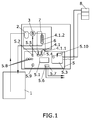
- the present invention refers to a viscometer sucking in the fluid from a tank (1) by means of a pump (3) that makes the fluid circulates through a filter (2) that can be placed before or after the pump, where in this preferred embodiment, the fluid is fuel oil.
- This pump (3) is connected to a microcontroller (5.1) integrated in a driver card (5) with a digital motor drive (5.2) that activates the pump (3) when is necessary the input of fluid in the tank (4) and deactivates the pump (3) when is not necessary more input of fluid in the tank (4).
- a differential pressure sensor (4.1) integrated in a driver card (5) is connected to two pressure inlets, one inside the tank (4.1.2) and the other in contact with the air (4.1.1).
- This differential pressure sensor permits the microcontroller (5.1) to know continuously the height of the fluid inside the tank, to deactivate the pump (3) once a set pressure is reached, and to begin the counting of the tank (4) emptying time as the time when the pressure goes down from a high pressure point to a low pressure point.
- the emptying of the tank (4) is made through a capillary (6) that is connected to the tank of the fluid.
- the driver card (5) presents a source of electricity (5.3) that when is connected to the power supply (8), it feeds the microcontroller (5.1), the differential pressure sensor (4.1) and the rest of the components of the driver card.
- This components are some connectors for the reading of the analogical inputs, like the analogical inputs of the temperature (5.5) of the fluid, the analogical outputs of the viscosity (5.6) and temperature (5.7) of the fluid and led diodes (5.8) for indicating the alarms relative to pump (3) failures, the blockade of the filter (2) and failures in the temperature sensors (7) submerged in the tank (4).
- the alarm relating to pump (3) failures consists of a detection system that once the pump (3) is activated, a time counter (not shown) is also activated. If in the maximum permitted time for the filling of the tank (4) the maximum pressure is not reached, the process is stopped, the pump (3) stops and the alarm is activated through a first led diode.
- the alarm relating to failures in the temperature sensor consists of a detection system that if the input value is out of the specified limits, the alarm is activated through a second led diode.
- the alarm relating to failures in the differential pressure sensor (4.1) consists of a detection system that if the tension value produced by the sensor (4.1) is out of the specified limits, the alarm is activated through a third led diode.
- driver card (5) presents a communications port RS-232 with a PC for loading software and for the introduction or the modification of parameters.
- the driver card (5) presents a button to make a manual reset, activate the sequence of the measurement of the viscosity and make its own auto calibration.
- the capillary (6) is interchangeable and the tank (4) is disposable, whereas in other examples of embodiment, the capillary (6) is integrated or overmolded in a disposable tank (4).
- the microcontroller of the viscometer determines the viscosity and the temperature of the fluid by means of a method consisting of these following stages:
Landscapes
- Physics & Mathematics (AREA)
- Health & Medical Sciences (AREA)
- Life Sciences & Earth Sciences (AREA)
- Chemical & Material Sciences (AREA)
- Analytical Chemistry (AREA)
- Biochemistry (AREA)
- General Health & Medical Sciences (AREA)
- General Physics & Mathematics (AREA)
- Immunology (AREA)
- Pathology (AREA)
- Measuring Fluid Pressure (AREA)
- Control Of Positive-Displacement Pumps (AREA)
Applications Claiming Priority (1)
| Application Number | Priority Date | Filing Date | Title |
|---|---|---|---|
| PCT/ES2010/070147 WO2011110699A1 (es) | 2010-03-11 | 2010-03-11 | Viscosímetro y procedimiento para determinar la viscosidad de un fluido |
Publications (1)
| Publication Number | Publication Date |
|---|---|
| EP2458366A1 true EP2458366A1 (de) | 2012-05-30 |
Family
ID=43333015
Family Applications (1)
| Application Number | Title | Priority Date | Filing Date |
|---|---|---|---|
| EP10714337A Withdrawn EP2458366A1 (de) | 2010-03-11 | 2010-03-11 | Viskometer und verfahren zur bestimmung der viskosität einer flüssigkeit |
Country Status (2)
| Country | Link |
|---|---|
| EP (1) | EP2458366A1 (de) |
| WO (1) | WO2011110699A1 (de) |
Families Citing this family (1)
| Publication number | Priority date | Publication date | Assignee | Title |
|---|---|---|---|---|
| CN113533136B (zh) * | 2021-08-18 | 2024-11-01 | 上海孚凌自动化控制系统股份有限公司 | 一种粘度计 |
Family Cites Families (5)
| Publication number | Priority date | Publication date | Assignee | Title |
|---|---|---|---|---|
| GB1379470A (en) * | 1972-08-01 | 1975-01-02 | A C I Operations | Viscometers |
| GB9021777D0 (en) * | 1990-10-06 | 1990-11-21 | Willett Int Ltd | Device and method |
| US6474143B1 (en) * | 2000-09-05 | 2002-11-05 | Dynamic Solutions, Inc. | Automatically monitoring density and viscosity of a liquid |
| RU2196317C2 (ru) | 2000-12-28 | 2003-01-10 | Безруков Виктор Иванович | Способ измерения вязкости жидкости и устройство для его осуществления |
| US7237431B2 (en) * | 2005-05-10 | 2007-07-03 | On-Site Analysis, Inc. | Apparatus and method for measuring viscosity |
-
2010
- 2010-03-11 WO PCT/ES2010/070147 patent/WO2011110699A1/es not_active Ceased
- 2010-03-11 EP EP10714337A patent/EP2458366A1/de not_active Withdrawn
Non-Patent Citations (1)
| Title |
|---|
| See references of WO2011110699A1 * |
Also Published As
| Publication number | Publication date |
|---|---|
| WO2011110699A1 (es) | 2011-09-15 |
Similar Documents
| Publication | Publication Date | Title |
|---|---|---|
| EP3021888B1 (de) | Relative pumpenkalibrierung zur ultrafiltrationssteuerung in einer dialysevorrichtung | |
| JP3682138B2 (ja) | 分注装置 | |
| CN100447545C (zh) | 检漏仪 | |
| US20040231414A1 (en) | Method for detecting a liquid level in a container in a circuit and a dialysis machine for actuating the method | |
| CN106168209B (zh) | 一种用于蠕动泵的智能流量校正方法和系统 | |
| CN106794429B (zh) | 用于对过滤器元件进行完整性检测的方法和设备 | |
| US10031152B2 (en) | Automatic analyzer | |
| EP3058347B1 (de) | Photometrische messzelle | |
| EP2847552B1 (de) | Vorrichtung zur milchfüllstandsmessung und entsprechendes messverfahren | |
| WO2000002016A1 (en) | Determining when fluid has stopped flowing within an element | |
| EP3187735A1 (de) | Pumpensystem sowie pumpendurchflussbestimmungsverfahren | |
| US11578301B2 (en) | Method of actuation of an alternating tangential flow diaphragm pump | |
| KR102424272B1 (ko) | 용기 충진 방법 | |
| JP6278407B2 (ja) | 液体の計量装置の充填の間の異常の検出方法及び液体の計量装置 | |
| CN111207805A (zh) | 一种压力容器液量检测装置及方法 | |
| EP2458366A1 (de) | Viskometer und verfahren zur bestimmung der viskosität einer flüssigkeit | |
| EP2623139A1 (de) | Peritonealdialysesystem | |
| JP2013044530A (ja) | 分注装置 | |
| CN212429168U (zh) | 一种水泵扬程流量测试装置 | |
| US12181330B2 (en) | Apparatus and method for the automatic, weight-dependent filling of a hose system | |
| US12214112B2 (en) | Method for checking the conveying accuracy of conveying devices of a medical treatment apparatus, and apparatuses | |
| CN113985497B (zh) | 一种自动检测标准储水容器的装置 | |
| CN206495771U (zh) | 一种用于蠕动泵的智能流量校正系统和蠕动泵 | |
| CN108612707B (zh) | 引射泵测试方法 | |
| CN108194342B (zh) | 引射泵测试装置 |
Legal Events
| Date | Code | Title | Description |
|---|---|---|---|
| PUAI | Public reference made under article 153(3) epc to a published international application that has entered the european phase |
Free format text: ORIGINAL CODE: 0009012 |
|
| 17P | Request for examination filed |
Effective date: 20111227 |
|
| AK | Designated contracting states |
Kind code of ref document: A1 Designated state(s): AT BE BG CH CY CZ DE DK EE ES FI FR GB GR HR HU IE IS IT LI LT LU LV MC MK MT NL NO PL PT RO SE SI SK SM TR |
|
| DAX | Request for extension of the european patent (deleted) | ||
| GRAP | Despatch of communication of intention to grant a patent |
Free format text: ORIGINAL CODE: EPIDOSNIGR1 |
|
| INTG | Intention to grant announced |
Effective date: 20150423 |
|
| STAA | Information on the status of an ep patent application or granted ep patent |
Free format text: STATUS: THE APPLICATION IS DEEMED TO BE WITHDRAWN |
|
| 18D | Application deemed to be withdrawn |
Effective date: 20150904 |