EP2458320A1 - Contact type shape measuring apparatus - Google Patents
Contact type shape measuring apparatus Download PDFInfo
- Publication number
- EP2458320A1 EP2458320A1 EP11186435A EP11186435A EP2458320A1 EP 2458320 A1 EP2458320 A1 EP 2458320A1 EP 11186435 A EP11186435 A EP 11186435A EP 11186435 A EP11186435 A EP 11186435A EP 2458320 A1 EP2458320 A1 EP 2458320A1
- Authority
- EP
- European Patent Office
- Prior art keywords
- probe
- speed
- target
- force
- acting force
- Prior art date
- Legal status (The legal status is an assumption and is not a legal conclusion. Google has not performed a legal analysis and makes no representation as to the accuracy of the status listed.)
- Granted
Links
- 239000000523 sample Substances 0.000 claims abstract description 206
- 230000003287 optical effect Effects 0.000 description 13
- 238000000034 method Methods 0.000 description 12
- 230000007246 mechanism Effects 0.000 description 10
- 238000006073 displacement reaction Methods 0.000 description 8
- 238000005259 measurement Methods 0.000 description 8
- 238000000465 moulding Methods 0.000 description 4
- 230000008569 process Effects 0.000 description 4
- 230000008859 change Effects 0.000 description 3
- 239000000463 material Substances 0.000 description 3
- 239000000428 dust Substances 0.000 description 2
- 230000003247 decreasing effect Effects 0.000 description 1
- 230000003111 delayed effect Effects 0.000 description 1
- 230000000694 effects Effects 0.000 description 1
- 238000001914 filtration Methods 0.000 description 1
- 238000012986 modification Methods 0.000 description 1
- 230000004048 modification Effects 0.000 description 1
- 230000010355 oscillation Effects 0.000 description 1
- 230000001737 promoting effect Effects 0.000 description 1
- 230000004044 response Effects 0.000 description 1
- 239000004065 semiconductor Substances 0.000 description 1
Images


Classifications
-
- G—PHYSICS
- G01—MEASURING; TESTING
- G01B—MEASURING LENGTH, THICKNESS OR SIMILAR LINEAR DIMENSIONS; MEASURING ANGLES; MEASURING AREAS; MEASURING IRREGULARITIES OF SURFACES OR CONTOURS
- G01B5/00—Measuring arrangements characterised by the use of mechanical techniques
- G01B5/004—Measuring arrangements characterised by the use of mechanical techniques for measuring coordinates of points
- G01B5/008—Measuring arrangements characterised by the use of mechanical techniques for measuring coordinates of points using coordinate measuring machines
-
- G—PHYSICS
- G01—MEASURING; TESTING
- G01B—MEASURING LENGTH, THICKNESS OR SIMILAR LINEAR DIMENSIONS; MEASURING ANGLES; MEASURING AREAS; MEASURING IRREGULARITIES OF SURFACES OR CONTOURS
- G01B21/00—Measuring arrangements or details thereof, where the measuring technique is not covered by the other groups of this subclass, unspecified or not relevant
- G01B21/02—Measuring arrangements or details thereof, where the measuring technique is not covered by the other groups of this subclass, unspecified or not relevant for measuring length, width, or thickness
- G01B21/04—Measuring arrangements or details thereof, where the measuring technique is not covered by the other groups of this subclass, unspecified or not relevant for measuring length, width, or thickness by measuring coordinates of points
- G01B21/045—Correction of measurements
Definitions
- the present invention relates to contact type shape measuring apparatuses, and more particularly, to a contact type shape measuring apparatus that precisely measures a surface shape of a diffraction optical element or a molding die used to form the diffraction optical element.
- diffraction optical elements utilizing light diffraction have recently been used in various products.
- a phase difference of light is frequently formed by regularly arranging stepped portions having heights ranging from several tens of micrometers to submicrometers so as to cause diffraction.
- a contact type shape measuring apparatus has been used widely.
- Japanese Patent Laid-Open No. 10-19504 discloses an example of a contact type shape measuring apparatus that measures a surface shape of a target surface of an optical element or an optical-element molding die serving as a target object to be measured.
- a contact type shape measuring apparatus that measures a surface shape of a target surface of an optical element or an optical-element molding die serving as a target object to be measured.
- a probe elastically supported by a moving member such as an XYZ slider
- a holder including a spring mechanism for holding the probe is provided between the probe and the moving member.
- the probe When the moving member is driven in the XY directions, the probe traces the shape of the target surface in the Z-direction while moving in the XY-directions.
- the moving member is controlled so as to follow in the Z-direction to maintain a pressing force corresponding to a predetermined contact force.
- the probe is scanned over the entire target surface to obtain measurement data. Measurement data obtained in a series of scanning operations reflects the shape of the target surface. By analyzing the measurement data, the shape of the target surface can be measured.
- the contact force of the probe with the target surface is minimized.
- Japanese Patent Laid-Open No. 2007-57308 discloses a probe that shortens such an unstable period.
- a force generating unit is provided in a housing of the probe.
- acting force is quickly applied to the probe so as to return the probe onto a target surface to be measured.
- a controller detects the bounce of the probe, it applies, to the probe, an acting force for cancelling the bounce of the probe.
- the acting force is applied by multiplying a proportionality coefficient in accordance with the relative displacement or relative speed between the probe and the moving member.
- the probe When the probe passes over an obstacle serving as a disturbance factor, such as dust, a projection, or a flaw, adhering to a continuously extending target surface, the probe is bounced by collision with the disturbance factor. As a result, the probe moves away from the target surface.
- the probe when a surface having a stepped portion like a diffraction optical element is measured, the probe sometimes measures a higher portion of the surface, passes over the stepped portion, and subsequently measures a lower portion of the surface. In this case, after passing over, the probe separates from the surface even if it does not bounce.
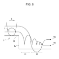
- Fig. 6 illustrates how to scan a surface having a stepped portion in the related art disclosed in Japanese Patent Laid-Open No. 2007-57308 .
- a target surface 2a of a target object 2 to be measured has a stepped portion 2s.
- a probe 1 provided in a moving member (not illustrated) is subjected to copy scanning in a direction D that is orthogonal to a ridge line of the stepped portion 2s and extends beyond the stepped portion 2s.
- a ball formed of a highly abrasive resistant material is provided to contact with the target surface 2a.
- t1b represents the behavior of the center of the ball of the probe 1
- T9B represents the behavior of the unillustrated moving member. For easy viewing, T9b is shown near T1b.
- the probe 1 leaps over the stepped portion 2s, temporarily separates from the target surface 2a, but falls with time. After that, the probe 1 collides with the target surface 2a again, and is bounced by reactive force resulting from the collision.
- the moving member that elastically supports the probe 1 is heavier and moves more slowly than the probe 1. For this reason, the moving member is delayed and follows the probe 1 during a period B1. During a period B2, the moving member overshoots beyond the height of the stepped portion 2s. Although the moving member sometimes repeats vibration, it is assumed here, for easy explanation, that the moving member is stabilized after the period B2.
- the probe 1 If the probe 1 is moved in conformity with the behavior of the moving member during the period B1, acting force is applied to the probe so that the probe does not separate from the moving member. Hence, the probe 1 floats above the target surface 2a. Conversely, during the period B2, the probe 1 is pressed against the target surface 2a with an excessive acting force. If the probe 1 is pressed with an excessive acting force, the contact force inevitably increases, and the probe 1 is bounced more by reactive force received from the target surface 2a.
- the present invention provides a contact type shape measuring apparatus that can shorten an unstable period even when a target surface has a stepped portion.
- the present invention in its aspect provides a shape measuring apparatus as specified in claims 1 to 4.
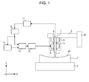
- Fig. 1 illustrates a configuration of a contact type shape measuring apparatus according to an embodiment of the present invention.
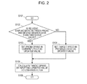
- Fig. 2 is a flowchart showing a method for calculating a target speed in the embodiment.
- Fig. 3 is a flowchart showing a method for calculating an acting force in the embodiment.
- Figs. 4A to 4C illustrate how to scan a stepped portion in the embodiment.
- Fig. 5 explains the change in acting force in the embodiment.
- Fig. 6 illustrates how to scan a surface having a stepped portion in the related art.
- Fig. 1 illustrates a configuration of a contact type shape measuring apparatus according to the embodiment of the present invention.
- the contact type shape measuring apparatus of the embodiment conducts copy scanning on a target surface 2a of a target object 2 to be measured with a probe 1.
- the target object 2 is set on a surface plate 3.
- the surface plate 3 can have a vibration preventing function for suppressing the influence of vibration from the floor. Further, the surface plate 3 can have a structure and a material that are unlikely to be deformed by the temperature change.
- a mirror 4 is provided at a rear end of the probe 1, and measures a three-dimensional position of the probe 1, for example, by interferometric measurement.
- the probe 1 is supported in a housing 6 with a linear guide 5 being disposed therebetween, and is movable in one axial direction relative to the housing 6.
- the linear guide 5 can adopt, for example, an air bearing such as to be easily movable in a moving direction and to have high rigidity in a direction orthogonal to the moving direction.
- the housing 6 is provided with a spring mechanism 7 such that the weight of the probe 1 is compensated and such that the probe 1 can be pressed against the target surface 2a with a specified contact force.
- the spring mechanism 7 is formed by a leaf spring using the rigidity of the material or an electromagnetic spring using magnetic force.
- the housing 6 is provided with a force generating unit 8 that applies acting force to the probe 1.
- the force generating unit 8 can be an electromagnet type mechanism that adjusts the magnitude of generated force by controlling the current flowing through a coil according to an input signal.
- the spring mechanism 7 can generate a fixed acting force. While both the spring mechanism 7 and the force generating unit 8 are mounted in the embodiment, acting force acting on the probe 1 may be generated only by the force generating unit 8 without providing the spring mechanism 7.
- the contact force of the probe 1 with the target object 2 can be adjusted by controlling the current so as to adjust the acting force to be applied to the probe 1.
- the housing 6 is provided at a distal end of a moving member 9.
- the moving member 9 is attached to a driving unit 10 and is movable three-dimensionally.
- the driving unit 10 can have a structure suitable for the shape of the surface of the target object 2, for example, a structure capable of driving in three-axis translation directions, or in two-axis translation directions and a one-axis rotation direction.
- the driving unit 10 drives the moving member 9 to maintain a constant relative displacement between the probe 1 and the moving member 9.
- the moving member 9 and the driving unit 10 are formed by a ball screw type XYZ slider in which intersecting columnar bodies are moved by driving force generated by a motor.
- the target-speed calculation unit 13 may calculate an inclination in the probe scanning direction by using a continuous function after a stepped portion is removed from the designed shape of the target surface 2a, without using the above probe speed.
- the force generating unit 8 can cut an acting force in a direction in which the probe 1 moves away from the target surface 2a or cut an acting force larger than a specified value even in a direction in which the probe 1 moves closer to the target surface 2a. Further, digital filtering may be performed to reduce high-frequency signals and signals of specific frequencies.
- Fig. 2 is a flowchart showing a detailed method for calculating a probe target speed, corresponding to the above process (3), according to the present invention.
- Step S101 a probe speed in the current cycle calculated by the probe-speed calculation unit 12 is input.
- the probe speed can be obtained by calculating dz/dt.
- the value dz/dt indicates the amount of displacement of the probe 1 in the Z-direction at a certain time interval, and can be easily obtained from data on the measured three-dimensional positions of the probe 1 sampled at the specific time intervals.
- the vector direction of the probe speed to be found is not limited to the Z-direction
- the probe speed in the Z-direction that is, dz/dt is given as an example for the following description.
- Step S102 it is determined whether or not the relative displacement between the probe 1 and the moving member 9 is less than or equal to a threshold value.
- the probe speed in the current cycle is set as an updated probe target speed. The difference between the probe speed and the probe target speed is substantially zero.
- Step S104 the probe speed in the current cycle is not used as a probe target speed, but the target speed in the previous cycle is set as an updated value.
- Step S105 the updated value is input to a low-pass filter, and a probe target speed is calculated.
- Step S106 the calculated probe target speed is output.
- the probe speed in a period before scanning of the stepped portion can be set as the probe target speed.
- the target speed may be set by being converted into an axial direction component of the probe 1 (a direction perpendicular to the direction D in Fig. 4 ) instead of being converted into the component in the direction along the target surface 2a.
- another way to set the probe target speed with reference to past information is to set, as the target speed, a probe speed along the target surface 2a in a period before the probe 1 passes over the stepped portion, by determining the position of the stepped portion from the designed shape.
- the designed shape of the target surface 2a and the scanning speed of the probe 1 are determined beforehand, it is possible to easily calculate the probe speed during scanning along the target surface 2a.
- Fig. 3 is a flowchart explaining a method for calculating an acting force to be applied to the probe 1 of the embodiment, corresponding to the above process (4), on the basis of the probe target speed obtained in the above process (3) and the calculated probe speed.
- Step S111 the probe target speed and the probe speed are input.
- Step S112 a probe speed error is calculated by subtracting the current probe speed from the set probe target speed.
- Step S113 it is determined, on the basis of the probe speed error, whether the probe 1 is stably scanning, falling, or bouncing. When the probe speed error is within a predetermined threshold range, it is determined that the probe 1 is stably scanning, and the procedure proceeds to Step S114. When the probe speed error comes out of the threshold range in a direction such that the probe 1 moves closer to the target surface 2a, it is determined that the probe 1 is falling, and the procedure proceeds to Step S115.
- Step S116 When the probe speed error comes out of the threshold range in a direction such that the probe 1 moves away from the target surface 2a, it is determined that the probe 1 is bouncing, and the procedure proceeds to Step S116.
- Step S114 no force is applied as an acting force because the probe 1 is in a stable scanning state.
- the force generating unit 8 also functions as the spring mechanism 7
- a force corresponding to the spring mechanism 7 is set as an acting force.
- Step S115 a force for promoting the fall is set as an acting force. For example, a fixed value fc is applied.
- Step S116 a viscous force for suppressing the behavior of the probe 1 is set as an acting force.
- an acting force is obtained by multiplying the probe speed error by a viscosity coefficient cv.
- the obtained acting force is output.
- the acting-force calculation unit 14 further calculates a fixed acting force in a direction such that the probe 1 moves closer to the target object.
- the fixed value fc When the fixed value fc is too small, the fall cannot be promoted, and the floating time increases. This makes it difficult to shorten an unstable period. In contrast, when the fixed value fc is too large, when the probe 1 collides with the target surface, it makes a flaw thereon. For this reason, the fixed value fc can be set to be as small as possible in correspondence with an allowable unstable period. Further, to suppress the occurrence of a flaw, for example, the acting force fc is cut when the probe speed exceeds a specified value.
- the viscosity coefficient cv is properly adjusted within a stable range by measuring the frequency response.
- Figs. 4A to 4C illustrate how to scan a stepped portion 2s provided on the target surface 2a of the target object 2 according to the embodiment of the present invention.
- the probe 1 is subjected to copy scanning in a direction D which is orthogonal to a ridge line of the stepped portion 2s and in which the probe 1 leaps from the stepped portion 2s.
- the direction D may be determined from the designed shape.
- T1 represents the behavior of the ball center of the probe 1
- f1 represents the acting force.
- the probe speed v1, the target speed vt, the threshold value e1 used to determine a falling state, and the threshold value e2 used to determine a bouncing state are shown in a lower part in correspondence with the behavior T1 of the ball center.
- the probe 1 falls beyond the stepped portion 2s.
- the probe speed error e exceeds e1
- the acting force f1 is set at fc, so that the fall is promoted.
- the probe 1 collides with the target surface 2a again, and is thereby bounced.
- the probe speed error e exceeds e2
- the acting force f1 is set at the viscous force cvxe (the probe speed error e is multiplied by a proportionality coefficient cv serving as the viscosity coefficient), so that bouncing is suppressed.
- the probe speed error e returns within the range of e1 to e2 again. Hence, it is determined that the probe 1 is in a stable scanning state.
- the acting force for reducing the probe speed error is calculated and is applied in the moving direction of the probe 1.
- Fig. 5 explains the change in acting force in the embodiment of the present invention.
- the horizontal axis indicates the time, and the vertical axis indicates the probe speed v1, the probe target speed vt, and the acting force f1.
- the values in a state in which the probe 1 passes over the stepped portion at a time 0 are plotted.
- the probe target speed vt and the probe speed v1 are shown together in an upper part of Fig. 5 , and the force acting on the probe 1 is shown in a lower part of Fig. 5 .
- the probe speed is set such as to have a positive value in a vertical upward direction.
- the target surface 2a has the stepped portion 2s sloping downward in the scanning direction D, as illustrated in Figs. 4A to 4C .
- the probe 1 falls in a vertical downward direction as it is scanned along the target surface 2a. Hence, vt takes a negative value.
- the fall is promoted by applying a fixed value (the probe speed v1 is decreasing, that is, the pressing force is increasing).
- the probe speed v1 is decreasing, that is, the pressing force is increasing.
- the bouncing is suppressed by applying the viscous force as the acting force (the increase in probe speed is suppressed by applying a force in an opposite direction in proportion to the probe speed v1).
- the acting force such that the probe moves in accordance with the behavior of the moving member is not applied. For this reason, the acting force can be applied to stabilize the probe, regardless of whether or not the moving member is stable. After that, the probe returns to a stable scanning state in a short time.
- the target surface is a flat surface having a stepped portion.
- a spherical, aspherical, or free-form surface having a stepped portion can be regarded similar to the flat surface having the stepped portion as long as the unstable period can be stabilized in a small area of, for example, 30 ⁇ m or less.
- the scanning speed of the probe is fixed.
- this case can be regarded as similar to the case in which the scanning speed is fixed.
- the contact type shape measuring apparatus of the present invention it is possible to shorten the unstable period during measurement of a surface having a stepped portion.
- the present invention relates to a contact type shape measuring apparatus, and more particularly, the present invention is suitably used to precisely measure the surface shape of a diffraction optical element or a molding die for producing the diffraction optical element.
- An acting force is applied to a probe (1) on the basis of a target speed serving as a probe speed in a stable copy scanning state of a target surface (2a) to be measured and a probe speed error serving as a difference between the target speed and a probe speed.
Landscapes
- Physics & Mathematics (AREA)
- General Physics & Mathematics (AREA)
- A Measuring Device Byusing Mechanical Method (AREA)
Abstract
Description
- The present invention relates to contact type shape measuring apparatuses, and more particularly, to a contact type shape measuring apparatus that precisely measures a surface shape of a diffraction optical element or a molding die used to form the diffraction optical element.
- With increase in performance of various optical apparatuses such as an image pickup camera, a laser beam printer, a copying machine, and a semiconductor exposure apparatus, requirements for optical elements to be mounted in these optical apparatuses are becoming increasing high. In particular, diffraction optical elements utilizing light diffraction have recently been used in various products. In diffraction optical elements, a phase difference of light is frequently formed by regularly arranging stepped portions having heights ranging from several tens of micrometers to submicrometers so as to cause diffraction. To measure a surface shape of an optical element having a stepped portion or a surface shape of an optical-element molding die, a contact type shape measuring apparatus has been used widely.
- Japanese Patent Laid-Open No.
10-19504 - In order to cause the probe to perform precise copy scanning of the target surface, the contact force of the probe with the target surface is minimized.
- However, in a case in which the contact force is reduced, if a dust, a projection, or a flaw exists on the target surface, the probe is prone to bounce, and the behavior of the probe becomes unstable. Accurate data cannot be obtained during an unstable period from when the probe bounces from the target surface to when vibration is settled.
- Japanese Patent Laid-Open No.
2007-57308 - When the target surface has discontinuous stepped portions like the diffraction optical element, there are the following problems.
- When the probe passes over an obstacle serving as a disturbance factor, such as dust, a projection, or a flaw, adhering to a continuously extending target surface, the probe is bounced by collision with the disturbance factor. As a result, the probe moves away from the target surface. In contrast, when a surface having a stepped portion like a diffraction optical element is measured, the probe sometimes measures a higher portion of the surface, passes over the stepped portion, and subsequently measures a lower portion of the surface. In this case, after passing over, the probe separates from the surface even if it does not bounce.
-
Fig. 6 illustrates how to scan a surface having a stepped portion in the related art disclosed in Japanese Patent Laid-Open No.2007-57308 - A
target surface 2a of atarget object 2 to be measured has astepped portion 2s. Aprobe 1 provided in a moving member (not illustrated) is subjected to copy scanning in a direction D that is orthogonal to a ridge line of thestepped portion 2s and extends beyond thestepped portion 2s. At a tip of theprobe 1, a ball formed of a highly abrasive resistant material is provided to contact with thetarget surface 2a. InFig. 6 , t1b represents the behavior of the center of the ball of theprobe 1, and T9B represents the behavior of the unillustrated moving member. For easy viewing, T9b is shown near T1b. Theprobe 1 leaps over thestepped portion 2s, temporarily separates from thetarget surface 2a, but falls with time. After that, theprobe 1 collides with thetarget surface 2a again, and is bounced by reactive force resulting from the collision. In general, the moving member that elastically supports theprobe 1 is heavier and moves more slowly than theprobe 1. For this reason, the moving member is delayed and follows theprobe 1 during a period B1. During a period B2, the moving member overshoots beyond the height of thestepped portion 2s. Although the moving member sometimes repeats vibration, it is assumed here, for easy explanation, that the moving member is stabilized after the period B2. If theprobe 1 is moved in conformity with the behavior of the moving member during the period B1, acting force is applied to the probe so that the probe does not separate from the moving member. Hence, theprobe 1 floats above thetarget surface 2a. Conversely, during the period B2, theprobe 1 is pressed against thetarget surface 2a with an excessive acting force. If theprobe 1 is pressed with an excessive acting force, the contact force inevitably increases, and theprobe 1 is bounced more by reactive force received from thetarget surface 2a. - In the above-described related art of Japanese Patent Laid-Open No.
2007-57308 - The present invention provides a contact type shape measuring apparatus that can shorten an unstable period even when a target surface has a stepped portion.
- The present invention in its aspect provides a shape measuring apparatus as specified in
claims 1 to 4. - Further features of the present invention will become apparent from the following description of exemplary embodiments with reference to the attached drawings.
-
Fig. 1 illustrates a configuration of a contact type shape measuring apparatus according to an embodiment of the present invention. -
Fig. 2 is a flowchart showing a method for calculating a target speed in the embodiment. -
Fig. 3 is a flowchart showing a method for calculating an acting force in the embodiment. -
Figs. 4A to 4C illustrate how to scan a stepped portion in the embodiment. -
Fig. 5 explains the change in acting force in the embodiment. -
Fig. 6 illustrates how to scan a surface having a stepped portion in the related art. - An embodiment of the present invention will be described with reference to the drawings.
-
Fig. 1 illustrates a configuration of a contact type shape measuring apparatus according to the embodiment of the present invention. - The contact type shape measuring apparatus of the embodiment conducts copy scanning on a
target surface 2a of atarget object 2 to be measured with aprobe 1. Thetarget object 2 is set on asurface plate 3. Thesurface plate 3 can have a vibration preventing function for suppressing the influence of vibration from the floor. Further, thesurface plate 3 can have a structure and a material that are unlikely to be deformed by the temperature change. Amirror 4 is provided at a rear end of theprobe 1, and measures a three-dimensional position of theprobe 1, for example, by interferometric measurement. Theprobe 1 is supported in ahousing 6 with alinear guide 5 being disposed therebetween, and is movable in one axial direction relative to thehousing 6. Thelinear guide 5 can adopt, for example, an air bearing such as to be easily movable in a moving direction and to have high rigidity in a direction orthogonal to the moving direction. Thehousing 6 is provided with aspring mechanism 7 such that the weight of theprobe 1 is compensated and such that theprobe 1 can be pressed against thetarget surface 2a with a specified contact force. Thespring mechanism 7 is formed by a leaf spring using the rigidity of the material or an electromagnetic spring using magnetic force. Besides thespring mechanism 7, thehousing 6 is provided with aforce generating unit 8 that applies acting force to theprobe 1. Theforce generating unit 8 can be an electromagnet type mechanism that adjusts the magnitude of generated force by controlling the current flowing through a coil according to an input signal. - The
spring mechanism 7 can generate a fixed acting force. While both thespring mechanism 7 and theforce generating unit 8 are mounted in the embodiment, acting force acting on theprobe 1 may be generated only by theforce generating unit 8 without providing thespring mechanism 7. - When the
force generating unit 8 is of an electromagnet type, the contact force of theprobe 1 with thetarget object 2 can be adjusted by controlling the current so as to adjust the acting force to be applied to theprobe 1. Further, thehousing 6 is provided at a distal end of a movingmember 9. The movingmember 9 is attached to a drivingunit 10 and is movable three-dimensionally. The drivingunit 10 can have a structure suitable for the shape of the surface of thetarget object 2, for example, a structure capable of driving in three-axis translation directions, or in two-axis translation directions and a one-axis rotation direction. The drivingunit 10 drives the movingmember 9 to maintain a constant relative displacement between theprobe 1 and the movingmember 9. For example, the movingmember 9 and the drivingunit 10 are formed by a ball screw type XYZ slider in which intersecting columnar bodies are moved by driving force generated by a motor. - During measurement, a flow of the following processes (1) to (5) serving as one cycle is repeated until the end of measurement:
- (1) A
position measuring unit 11, for example, using interferometric measurement samples three-dimensional positions of theprobe 1 at specified time intervals as information about the three-dimensional position from a reference position; - (2) A probe-
speed calculation unit 12 receives the position information about theprobe 1 and calculates a probe speed serving as information about the speed in a moving direction of theprobe 1 along thetarget surface 2a; - (3) A target-
speed calculation unit 13 receives the above probe speed and calculates a probe target speed; - (4) An acting-
force calculation unit 14 calculates an acting force to be applied to theprobe 1, on the basis of the probe target speed and the probe speed; and - (5) A
force control unit 15 applies, to theforce generating unit 8, a current in accordance with the acting force. - The target-
speed calculation unit 13 may calculate an inclination in the probe scanning direction by using a continuous function after a stepped portion is removed from the designed shape of thetarget surface 2a, without using the above probe speed. - The
force generating unit 8 can cut an acting force in a direction in which theprobe 1 moves away from thetarget surface 2a or cut an acting force larger than a specified value even in a direction in which theprobe 1 moves closer to thetarget surface 2a. Further, digital filtering may be performed to reduce high-frequency signals and signals of specific frequencies. - Structures characteristic of the present invention will be described in detail below.
-
Fig. 2 is a flowchart showing a detailed method for calculating a probe target speed, corresponding to the above process (3), according to the present invention. - In Step S101, a probe speed in the current cycle calculated by the probe-
speed calculation unit 12 is input. As an example, when a vertical direction is designated as a Z-direction and attention is paid to the Z-direction serving as one speed component in the moving direction of theprobe 1, the probe speed can be obtained by calculating dz/dt. The value dz/dt indicates the amount of displacement of theprobe 1 in the Z-direction at a certain time interval, and can be easily obtained from data on the measured three-dimensional positions of theprobe 1 sampled at the specific time intervals. - Although the vector direction of the probe speed to be found is not limited to the Z-direction, the probe speed in the Z-direction, that is, dz/dt is given as an example for the following description.
- In Step S102, it is determined whether or not the relative displacement between the
probe 1 and the movingmember 9 is less than or equal to a threshold value. When the relative displacement therebetween is less than or equal to the threshold value, there is a high possibility theprobe 1 is stably scanning thetarget surface 2a. In this case, in Step S103, the probe speed in the current cycle is set as an updated probe target speed. The difference between the probe speed and the probe target speed is substantially zero. - In contrast, when the relative displacement between the
probe 1 and the movingmember 9 exceeds the threshold value, there is a high possibility that theprobe 1 is falling off thetarget surface 2a or is bouncing. In this case, in Step S104, the probe speed in the current cycle is not used as a probe target speed, but the target speed in the previous cycle is set as an updated value. Next, in Step S105, the updated value is input to a low-pass filter, and a probe target speed is calculated. In Step S106, the calculated probe target speed is output. According to the above-described method, in a state in which the probe is falling or bouncing, a probe speed in a stable scanning state can be set as a probe target speed with reference to past information. That is, in a period after scanning of the stepped portion, the probe speed in a period before scanning of the stepped portion can be set as the probe target speed. Alternatively, the target speed may be set by being converted into an axial direction component of the probe 1 (a direction perpendicular to the direction D inFig. 4 ) instead of being converted into the component in the direction along thetarget surface 2a. - For example, another way to set the probe target speed with reference to past information is to set, as the target speed, a probe speed along the
target surface 2a in a period before theprobe 1 passes over the stepped portion, by determining the position of the stepped portion from the designed shape. As long as the designed shape of thetarget surface 2a and the scanning speed of theprobe 1 are determined beforehand, it is possible to easily calculate the probe speed during scanning along thetarget surface 2a. - By applying a below-described acting force corresponding to the probe target speed after thus setting the past probe speed as the target speed of the probe that has passed over the stepped portion, an estimated error of the target speed resulting from working error and setting error of the target object can be reduced.
-
Fig. 3 is a flowchart explaining a method for calculating an acting force to be applied to theprobe 1 of the embodiment, corresponding to the above process (4), on the basis of the probe target speed obtained in the above process (3) and the calculated probe speed. - In Step S111, the probe target speed and the probe speed are input. In Step S112, a probe speed error is calculated by subtracting the current probe speed from the set probe target speed. In Step S113, it is determined, on the basis of the probe speed error, whether the
probe 1 is stably scanning, falling, or bouncing. When the probe speed error is within a predetermined threshold range, it is determined that theprobe 1 is stably scanning, and the procedure proceeds to Step S114. When the probe speed error comes out of the threshold range in a direction such that theprobe 1 moves closer to thetarget surface 2a, it is determined that theprobe 1 is falling, and the procedure proceeds to Step S115. When the probe speed error comes out of the threshold range in a direction such that theprobe 1 moves away from thetarget surface 2a, it is determined that theprobe 1 is bouncing, and the procedure proceeds to Step S116. In Step S114, no force is applied as an acting force because theprobe 1 is in a stable scanning state. However, when theforce generating unit 8 also functions as thespring mechanism 7, a force corresponding to thespring mechanism 7 is set as an acting force. In Step S115, a force for promoting the fall is set as an acting force. For example, a fixed value fc is applied. In Step S116, a viscous force for suppressing the behavior of theprobe 1 is set as an acting force. For example, an acting force is obtained by multiplying the probe speed error by a viscosity coefficient cv. In Step S117, the obtained acting force is output. In this way, when the probe speed error is less than the threshold value that is less than the probe target speed, the acting-force calculation unit 14 further calculates a fixed acting force in a direction such that theprobe 1 moves closer to the target object. Thus, it is possible to expect a further effect of restricting floating of theprobe 1. - When the fixed value fc is too small, the fall cannot be promoted, and the floating time increases. This makes it difficult to shorten an unstable period. In contrast, when the fixed value fc is too large, when the
probe 1 collides with the target surface, it makes a flaw thereon. For this reason, the fixed value fc can be set to be as small as possible in correspondence with an allowable unstable period. Further, to suppress the occurrence of a flaw, for example, the acting force fc is cut when the probe speed exceeds a specified value. - If the viscosity coefficient cv is too low, the viscous force is insufficient, and bouncing is not suppressed. This makes it difficult to shorten the unstable period. In contrast, when the viscosity coefficient cv is too high, oscillation occurs, and this also makes it difficult to shorten the unstable period. For this reason, for example, the viscosity coefficient cv is properly adjusted within a stable range by measuring the frequency response.
-
Figs. 4A to 4C illustrate how to scan a steppedportion 2s provided on thetarget surface 2a of thetarget object 2 according to the embodiment of the present invention. Theprobe 1 is subjected to copy scanning in a direction D which is orthogonal to a ridge line of the steppedportion 2s and in which theprobe 1 leaps from the steppedportion 2s. The direction D may be determined from the designed shape. - While the
probe 1 may be scanned in a direction different from the direction D by moving the movingmember 9 with force generated by the drivingunit 10, theprobe 1 may impair the shape of the steppedportion 2s, for example, because of collision with the steppedportion 2s. For this reason, theprobe 1 can be scanned in the direction D or a close direction. InFigs. 4A to 4C , T1 represents the behavior of the ball center of theprobe 1, and f1 represents the acting force. Further, the probe speed v1, the target speed vt, the threshold value e1 used to determine a falling state, and the threshold value e2 used to determine a bouncing state are shown in a lower part in correspondence with the behavior T1 of the ball center. The probe speed error e can be obtained by subtracting the probe speed v1 from the probe target speed vt (e = |vt-v1|).
Referring toFig. 4A , theprobe 1 is scanning a portion short of the steppedportion 2s. At this time, theprobe 1 is stably performing scanning, and the probe speed v1 is within the range of e1 to e2. For this reason, theforce generating unit 8 does not generate any force as the acting force f1 (f1 = 0), and does not apply any acting force to theprobe 1. - Referring to
Fig. 4B , theprobe 1 falls beyond the steppedportion 2s. When the probe speed error e exceeds e1, it is determined that theprobe 1 is falling, and the acting force f1 is set at fc, so that the fall is promoted. InFig. 4C , theprobe 1 collides with thetarget surface 2a again, and is thereby bounced. When the probe speed error e exceeds e2, it is determined that theprobe 1 is bouncing, and the acting force f1 is set at the viscous force cvxe (the probe speed error e is multiplied by a proportionality coefficient cv serving as the viscosity coefficient), so that bouncing is suppressed. When theprobe 1 is stabilized, the probe speed error e returns within the range of e1 to e2 again. Hence, it is determined that theprobe 1 is in a stable scanning state. - That is, on the basis of the probe speed error serving as the difference between the probe target speed and the probe speed, the acting force for reducing the probe speed error is calculated and is applied in the moving direction of the
probe 1. -
Fig. 5 explains the change in acting force in the embodiment of the present invention. The horizontal axis indicates the time, and the vertical axis indicates the probe speed v1, the probe target speed vt, and the acting force f1. The values in a state in which theprobe 1 passes over the stepped portion at atime 0 are plotted. The probe target speed vt and the probe speed v1 are shown together in an upper part ofFig. 5 , and the force acting on theprobe 1 is shown in a lower part ofFig. 5 . In the embodiment, the probe speed is set such as to have a positive value in a vertical upward direction. Further, it is assumed that thetarget surface 2a has the steppedportion 2s sloping downward in the scanning direction D, as illustrated inFigs. 4A to 4C . - Therefore, the
probe 1 falls in a vertical downward direction as it is scanned along thetarget surface 2a. Hence, vt takes a negative value. - When it is determined at a time a1 that the probe is falling, the fall is promoted by applying a fixed value (the probe speed v1 is decreasing, that is, the pressing force is increasing). Subsequently, when it is determined at a time a2 that the
probe 1 is bouncing, the bouncing is suppressed by applying the viscous force as the acting force (the increase in probe speed is suppressed by applying a force in an opposite direction in proportion to the probe speed v1). Here, unlike the related art, the acting force such that the probe moves in accordance with the behavior of the moving member is not applied. For this reason, the acting force can be applied to stabilize the probe, regardless of whether or not the moving member is stable. After that, the probe returns to a stable scanning state in a short time. - In the above-described embodiment, the target surface is a flat surface having a stepped portion. However, a spherical, aspherical, or free-form surface having a stepped portion can be regarded similar to the flat surface having the stepped portion as long as the unstable period can be stabilized in a small area of, for example, 30 µm or less.
- In the above embodiment, the scanning speed of the probe is fixed. However, when the unstable period terminates in a short time of 0.03 seconds or less and the scanning speed more gently changes than this, this case can be regarded as similar to the case in which the scanning speed is fixed.
- As described above, according to the contact type shape measuring apparatus of the present invention, it is possible to shorten the unstable period during measurement of a surface having a stepped portion.
- The present invention relates to a contact type shape measuring apparatus, and more particularly, the present invention is suitably used to precisely measure the surface shape of a diffraction optical element or a molding die for producing the diffraction optical element.
- While the present invention has been described with reference to exemplary embodiments, it is to be understood that the invention is not limited to the disclosed exemplary embodiments. The scope of the following claims is to be accorded the broadest interpretation so as to encompass all such modifications and equivalent structures and functions.
An acting force is applied to a probe (1) on the basis of a target speed serving as a probe speed in a stable copy scanning state of a target surface (2a) to be measured and a probe speed error serving as a difference between the target speed and a probe speed.
Claims (4)
- A shape measuring apparatus comprising:a moving member (9) configured to move three-dimensionally;a probe (1) supported movably relative to the moving member (9) ;position measuring means (11) configured to measure a position of the probe (1);probe-speed calculation means (12) configured to calculate a probe speed serving as speed information in a moving direction of the probe (1) on the basis of position information about the position of the probe (1) obtained by the position measuring means (11);target-speed calculation means (13) configured to calculate a probe target speed with reference to probe speed information during scanning of a target object (2) to be measured;acting-force calculation means (14) configured to calculate an acting force that reduces a probe speed error serving as a different between the probe target speed and the probe speed on the basis of the probe speed error; andforce generating means (8) configured to generate, in the probe (1), a force in the moving direction of the probe (1) in accordance with the calculated acting force;wherein the shape measuring apparatus measures a shape of the target object (2) by scanning a surface (2a) of the target object (2) and measuring the position of the probe (1) while the probe (1) is in contact with the target object (2).
- The shape measuring apparatus according to Claim 1,
wherein the target-speed calculation means sets the target speed with reference to past information about the probe speed. - The shape measuring apparatus according to Claim 1,
wherein the acting-force calculation means calculates the acting force by multiplying the probe speed error by a proportionality coefficient when the probe speed error exceeds a threshold value. - The shape measuring apparatus according to Claim 1,
wherein the acting-force calculation means calculates a fixed acting force when the probe speed error exceeds a threshold value.
Applications Claiming Priority (1)
| Application Number | Priority Date | Filing Date | Title |
|---|---|---|---|
| JP2010261597A JP5697416B2 (en) | 2010-11-24 | 2010-11-24 | Contact-type shape measuring device |
Publications (2)
| Publication Number | Publication Date |
|---|---|
| EP2458320A1 true EP2458320A1 (en) | 2012-05-30 |
| EP2458320B1 EP2458320B1 (en) | 2013-07-03 |
Family
ID=45375154
Family Applications (1)
| Application Number | Title | Priority Date | Filing Date |
|---|---|---|---|
| EP20110186435 Not-in-force EP2458320B1 (en) | 2010-11-24 | 2011-10-25 | Contact type shape measuring apparatus |
Country Status (3)
| Country | Link |
|---|---|
| US (1) | US9016106B2 (en) |
| EP (1) | EP2458320B1 (en) |
| JP (1) | JP5697416B2 (en) |
Families Citing this family (5)
| Publication number | Priority date | Publication date | Assignee | Title |
|---|---|---|---|---|
| JP2014074648A (en) * | 2012-10-04 | 2014-04-24 | Canon Inc | Contact type shape measuring apparatus and method |
| JP6133678B2 (en) * | 2013-05-01 | 2017-05-24 | 株式会社ミツトヨ | Surface texture measuring device and control method thereof |
| EP3147627B1 (en) * | 2015-09-22 | 2023-04-26 | GF Machining Solutions AG | Optical measuring probe calibration |
| CN111928748B (en) * | 2019-05-13 | 2022-05-13 | 安徽科瑞特模塑有限公司 | General detection tool for machining vehicle air guide sleeve |
| CN114812462B (en) * | 2022-06-22 | 2022-09-13 | 深圳市华盛源机电有限公司 | Precision dimension measurement system of vehicle-mounted electronic control cooling unit of new energy |
Citations (5)
| Publication number | Priority date | Publication date | Assignee | Title |
|---|---|---|---|---|
| EP0364057A2 (en) * | 1988-10-14 | 1990-04-18 | Hitachi Construction Machinery Co., Ltd. | Profiling control system for given curved surface |
| JPH1019504A (en) | 1996-07-02 | 1998-01-23 | Canon Inc | 3D shape measuring device |
| JP2007057308A (en) | 2005-08-23 | 2007-03-08 | Canon Inc | Contact probe |
| US20090271997A1 (en) * | 2006-11-17 | 2009-11-05 | Otto Ruck | Method and apparatus for determining spatial coordinates at a multiplicity of measurement points |
| EP2172736A1 (en) * | 2007-07-13 | 2010-04-07 | Ulvac, Inc. | Method for measuring surface profile of sample and apparatus for measuring surface profile of sample |
Family Cites Families (15)
| Publication number | Priority date | Publication date | Assignee | Title |
|---|---|---|---|---|
| JPS6412935A (en) * | 1987-07-02 | 1989-01-17 | Mitsubishi Electric Corp | Constant-speed travel device for vehicle |
| JPH06148363A (en) * | 1992-11-09 | 1994-05-27 | Alpine Electron Inc | Rotational operation apparatus |
| EP0849654B1 (en) * | 1996-12-21 | 2004-04-28 | Carl Zeiss | Control method for coordinate measuring devices and coordinate measuring device |
| JP2000155019A (en) * | 1998-11-18 | 2000-06-06 | Ricoh Co Ltd | Shape measuring device |
| JP4573992B2 (en) * | 2000-11-07 | 2010-11-04 | 株式会社東海理化電機製作所 | Window glass clamping presence / absence detection device |
| JP2003294434A (en) * | 2002-03-29 | 2003-10-15 | Ricoh Co Ltd | Contact probe |
| JP2003338035A (en) * | 2002-05-17 | 2003-11-28 | Matsushita Electric Ind Co Ltd | Disc determination method for optical disc device |
| JP2006340323A (en) * | 2005-06-06 | 2006-12-14 | Fujitsu Ten Ltd | Noise-sensitive volume controller and noise-sensitive volume control method |
| JP4704932B2 (en) * | 2005-09-28 | 2011-06-22 | 精 守安 | Stylus type shape measuring device and method and rotation restricting air cylinder suitable for the same |
| DE102006019382A1 (en) * | 2006-04-24 | 2007-10-25 | Carl Zeiss Industrielle Messtechnik Gmbh | Scanning a surface with a coordinate measuring machine |
| JP2007292674A (en) * | 2006-04-27 | 2007-11-08 | Hitachi Plant Technologies Ltd | Three-dimensional measurement method and apparatus |
| JP5192196B2 (en) * | 2007-08-03 | 2013-05-08 | 株式会社ミツトヨ | Surface shape measuring device |
| JP4532577B2 (en) * | 2008-05-23 | 2010-08-25 | ファナック株式会社 | Machine tool with numerical control device and on-machine measuring device |
| GB0900878D0 (en) * | 2009-01-20 | 2009-03-04 | Renishaw Plc | Method for optimising a measurement cycle |
| JP5848873B2 (en) * | 2011-01-05 | 2016-01-27 | 株式会社ミツトヨ | Control device and measuring device |
-
2010
- 2010-11-24 JP JP2010261597A patent/JP5697416B2/en not_active Expired - Fee Related
-
2011
- 2011-10-25 EP EP20110186435 patent/EP2458320B1/en not_active Not-in-force
- 2011-11-09 US US13/292,838 patent/US9016106B2/en not_active Expired - Fee Related
Patent Citations (5)
| Publication number | Priority date | Publication date | Assignee | Title |
|---|---|---|---|---|
| EP0364057A2 (en) * | 1988-10-14 | 1990-04-18 | Hitachi Construction Machinery Co., Ltd. | Profiling control system for given curved surface |
| JPH1019504A (en) | 1996-07-02 | 1998-01-23 | Canon Inc | 3D shape measuring device |
| JP2007057308A (en) | 2005-08-23 | 2007-03-08 | Canon Inc | Contact probe |
| US20090271997A1 (en) * | 2006-11-17 | 2009-11-05 | Otto Ruck | Method and apparatus for determining spatial coordinates at a multiplicity of measurement points |
| EP2172736A1 (en) * | 2007-07-13 | 2010-04-07 | Ulvac, Inc. | Method for measuring surface profile of sample and apparatus for measuring surface profile of sample |
Also Published As
| Publication number | Publication date |
|---|---|
| US20120125088A1 (en) | 2012-05-24 |
| EP2458320B1 (en) | 2013-07-03 |
| JP5697416B2 (en) | 2015-04-08 |
| US9016106B2 (en) | 2015-04-28 |
| JP2012112780A (en) | 2012-06-14 |
Similar Documents
| Publication | Publication Date | Title |
|---|---|---|
| EP2458320B1 (en) | Contact type shape measuring apparatus | |
| US7784333B2 (en) | Measurement control device and measurement control method | |
| US8353060B2 (en) | Scanning probe microscope and a measuring method using the same | |
| JP5754971B2 (en) | Shape measuring apparatus and shape measuring method | |
| EP2017570A1 (en) | Shape measuring device and method with regulated scanning force based on monitoring the position of a resiliently mounted probe with several interferometers. | |
| US20140071460A1 (en) | Positioning apparatus and measuring apparatus | |
| US7966867B2 (en) | Scanning probe microscope | |
| US7350404B2 (en) | Scanning type probe microscope and probe moving control method therefor | |
| JP2005138013A (en) | Droplet discharge device control method and droplet discharge device | |
| US20080087820A1 (en) | Probe control method for scanning probe microscope | |
| US20160284506A1 (en) | Stage Apparatus and Charged Particle Radiation Apparatus Equipped with Stage Apparatus | |
| US8120304B2 (en) | Method for improving motion times of a stage | |
| KR101607606B1 (en) | Measuring method for atomic force microscope | |
| US10955436B2 (en) | Scanning probe microscope | |
| US20080236259A1 (en) | Method of Control of Probe Scan and Apparatus for Controlling Probe Scan of Scanning Probe Microscope | |
| JP2003097938A (en) | Control device, control method, shape measuring device, and robot | |
| JPH08219752A (en) | Shape measuring device | |
| KR102632277B1 (en) | Stage movement control device and charged particle beam system | |
| JP2004028684A (en) | Shape measuring device and shape measuring method | |
| JP2008209238A (en) | Scanning probe microscope | |
| CN121323504B (en) | Methods, systems, and readable storage media for detecting high-speed scanning errors of digital pathology scanner stage | |
| JP2001249018A (en) | Apparatus and method for measuring surface mechanical properties | |
| JP2014074648A (en) | Contact type shape measuring apparatus and method | |
| JP2014199690A (en) | Magnetic head inspection device and magnetic head inspection method | |
| JP3474355B2 (en) | Shape measuring device |
Legal Events
| Date | Code | Title | Description |
|---|---|---|---|
| PUAI | Public reference made under article 153(3) epc to a published international application that has entered the european phase |
Free format text: ORIGINAL CODE: 0009012 |
|
| AK | Designated contracting states |
Kind code of ref document: A1 Designated state(s): AL AT BE BG CH CY CZ DE DK EE ES FI FR GB GR HR HU IE IS IT LI LT LU LV MC MK MT NL NO PL PT RO RS SE SI SK SM TR |
|
| AX | Request for extension of the european patent |
Extension state: BA ME |
|
| 17P | Request for examination filed |
Effective date: 20121130 |
|
| GRAP | Despatch of communication of intention to grant a patent |
Free format text: ORIGINAL CODE: EPIDOSNIGR1 |
|
| RIC1 | Information provided on ipc code assigned before grant |
Ipc: G01B 21/04 20060101ALI20130102BHEP Ipc: G01B 5/008 20060101AFI20130102BHEP |
|
| GRAS | Grant fee paid |
Free format text: ORIGINAL CODE: EPIDOSNIGR3 |
|
| GRAA | (expected) grant |
Free format text: ORIGINAL CODE: 0009210 |
|
| AK | Designated contracting states |
Kind code of ref document: B1 Designated state(s): AL AT BE BG CH CY CZ DE DK EE ES FI FR GB GR HR HU IE IS IT LI LT LU LV MC MK MT NL NO PL PT RO RS SE SI SK SM TR |
|
| REG | Reference to a national code |
Ref country code: GB Ref legal event code: FG4D |
|
| REG | Reference to a national code |
Ref country code: AT Ref legal event code: REF Ref document number: 620025 Country of ref document: AT Kind code of ref document: T Effective date: 20130715 Ref country code: CH Ref legal event code: EP |
|
| REG | Reference to a national code |
Ref country code: IE Ref legal event code: FG4D |
|
| REG | Reference to a national code |
Ref country code: DE Ref legal event code: R096 Ref document number: 602011002215 Country of ref document: DE Effective date: 20130829 |
|
| PG25 | Lapsed in a contracting state [announced via postgrant information from national office to epo] |
Ref country code: SI Free format text: LAPSE BECAUSE OF FAILURE TO SUBMIT A TRANSLATION OF THE DESCRIPTION OR TO PAY THE FEE WITHIN THE PRESCRIBED TIME-LIMIT Effective date: 20130703 |
|
| REG | Reference to a national code |
Ref country code: AT Ref legal event code: MK05 Ref document number: 620025 Country of ref document: AT Kind code of ref document: T Effective date: 20130703 |
|
| REG | Reference to a national code |
Ref country code: NL Ref legal event code: VDEP Effective date: 20130703 |
|
| REG | Reference to a national code |
Ref country code: LT Ref legal event code: MG4D |
|
| PG25 | Lapsed in a contracting state [announced via postgrant information from national office to epo] |
Ref country code: PT Free format text: LAPSE BECAUSE OF FAILURE TO SUBMIT A TRANSLATION OF THE DESCRIPTION OR TO PAY THE FEE WITHIN THE PRESCRIBED TIME-LIMIT Effective date: 20131104 Ref country code: HR Free format text: LAPSE BECAUSE OF FAILURE TO SUBMIT A TRANSLATION OF THE DESCRIPTION OR TO PAY THE FEE WITHIN THE PRESCRIBED TIME-LIMIT Effective date: 20130703 Ref country code: AT Free format text: LAPSE BECAUSE OF FAILURE TO SUBMIT A TRANSLATION OF THE DESCRIPTION OR TO PAY THE FEE WITHIN THE PRESCRIBED TIME-LIMIT Effective date: 20130703 Ref country code: SE Free format text: LAPSE BECAUSE OF FAILURE TO SUBMIT A TRANSLATION OF THE DESCRIPTION OR TO PAY THE FEE WITHIN THE PRESCRIBED TIME-LIMIT Effective date: 20130703 Ref country code: IS Free format text: LAPSE BECAUSE OF FAILURE TO SUBMIT A TRANSLATION OF THE DESCRIPTION OR TO PAY THE FEE WITHIN THE PRESCRIBED TIME-LIMIT Effective date: 20131103 Ref country code: NO Free format text: LAPSE BECAUSE OF FAILURE TO SUBMIT A TRANSLATION OF THE DESCRIPTION OR TO PAY THE FEE WITHIN THE PRESCRIBED TIME-LIMIT Effective date: 20131003 Ref country code: BE Free format text: LAPSE BECAUSE OF FAILURE TO SUBMIT A TRANSLATION OF THE DESCRIPTION OR TO PAY THE FEE WITHIN THE PRESCRIBED TIME-LIMIT Effective date: 20130703 Ref country code: LT Free format text: LAPSE BECAUSE OF FAILURE TO SUBMIT A TRANSLATION OF THE DESCRIPTION OR TO PAY THE FEE WITHIN THE PRESCRIBED TIME-LIMIT Effective date: 20130703 Ref country code: CY Free format text: LAPSE BECAUSE OF FAILURE TO SUBMIT A TRANSLATION OF THE DESCRIPTION OR TO PAY THE FEE WITHIN THE PRESCRIBED TIME-LIMIT Effective date: 20130911 |
|
| PG25 | Lapsed in a contracting state [announced via postgrant information from national office to epo] |
Ref country code: LV Free format text: LAPSE BECAUSE OF FAILURE TO SUBMIT A TRANSLATION OF THE DESCRIPTION OR TO PAY THE FEE WITHIN THE PRESCRIBED TIME-LIMIT Effective date: 20130703 Ref country code: PL Free format text: LAPSE BECAUSE OF FAILURE TO SUBMIT A TRANSLATION OF THE DESCRIPTION OR TO PAY THE FEE WITHIN THE PRESCRIBED TIME-LIMIT Effective date: 20130703 Ref country code: ES Free format text: LAPSE BECAUSE OF FAILURE TO SUBMIT A TRANSLATION OF THE DESCRIPTION OR TO PAY THE FEE WITHIN THE PRESCRIBED TIME-LIMIT Effective date: 20131014 Ref country code: FI Free format text: LAPSE BECAUSE OF FAILURE TO SUBMIT A TRANSLATION OF THE DESCRIPTION OR TO PAY THE FEE WITHIN THE PRESCRIBED TIME-LIMIT Effective date: 20130703 Ref country code: GR Free format text: LAPSE BECAUSE OF FAILURE TO SUBMIT A TRANSLATION OF THE DESCRIPTION OR TO PAY THE FEE WITHIN THE PRESCRIBED TIME-LIMIT Effective date: 20131004 Ref country code: NL Free format text: LAPSE BECAUSE OF FAILURE TO SUBMIT A TRANSLATION OF THE DESCRIPTION OR TO PAY THE FEE WITHIN THE PRESCRIBED TIME-LIMIT Effective date: 20130703 |
|
| PG25 | Lapsed in a contracting state [announced via postgrant information from national office to epo] |
Ref country code: CY Free format text: LAPSE BECAUSE OF FAILURE TO SUBMIT A TRANSLATION OF THE DESCRIPTION OR TO PAY THE FEE WITHIN THE PRESCRIBED TIME-LIMIT Effective date: 20130703 |
|
| PG25 | Lapsed in a contracting state [announced via postgrant information from national office to epo] |
Ref country code: RO Free format text: LAPSE BECAUSE OF FAILURE TO SUBMIT A TRANSLATION OF THE DESCRIPTION OR TO PAY THE FEE WITHIN THE PRESCRIBED TIME-LIMIT Effective date: 20130703 Ref country code: DK Free format text: LAPSE BECAUSE OF FAILURE TO SUBMIT A TRANSLATION OF THE DESCRIPTION OR TO PAY THE FEE WITHIN THE PRESCRIBED TIME-LIMIT Effective date: 20130703 Ref country code: EE Free format text: LAPSE BECAUSE OF FAILURE TO SUBMIT A TRANSLATION OF THE DESCRIPTION OR TO PAY THE FEE WITHIN THE PRESCRIBED TIME-LIMIT Effective date: 20130703 Ref country code: CZ Free format text: LAPSE BECAUSE OF FAILURE TO SUBMIT A TRANSLATION OF THE DESCRIPTION OR TO PAY THE FEE WITHIN THE PRESCRIBED TIME-LIMIT Effective date: 20130703 Ref country code: SK Free format text: LAPSE BECAUSE OF FAILURE TO SUBMIT A TRANSLATION OF THE DESCRIPTION OR TO PAY THE FEE WITHIN THE PRESCRIBED TIME-LIMIT Effective date: 20130703 |
|
| PLBE | No opposition filed within time limit |
Free format text: ORIGINAL CODE: 0009261 |
|
| STAA | Information on the status of an ep patent application or granted ep patent |
Free format text: STATUS: NO OPPOSITION FILED WITHIN TIME LIMIT |
|
| PG25 | Lapsed in a contracting state [announced via postgrant information from national office to epo] |
Ref country code: IT Free format text: LAPSE BECAUSE OF FAILURE TO SUBMIT A TRANSLATION OF THE DESCRIPTION OR TO PAY THE FEE WITHIN THE PRESCRIBED TIME-LIMIT Effective date: 20130703 Ref country code: MC Free format text: LAPSE BECAUSE OF FAILURE TO SUBMIT A TRANSLATION OF THE DESCRIPTION OR TO PAY THE FEE WITHIN THE PRESCRIBED TIME-LIMIT Effective date: 20130703 |
|
| 26N | No opposition filed |
Effective date: 20140404 |
|
| REG | Reference to a national code |
Ref country code: DE Ref legal event code: R097 Ref document number: 602011002215 Country of ref document: DE Effective date: 20140404 |
|
| REG | Reference to a national code |
Ref country code: IE Ref legal event code: MM4A |
|
| REG | Reference to a national code |
Ref country code: FR Ref legal event code: ST Effective date: 20140630 |
|
| PG25 | Lapsed in a contracting state [announced via postgrant information from national office to epo] |
Ref country code: FR Free format text: LAPSE BECAUSE OF NON-PAYMENT OF DUE FEES Effective date: 20131031 |
|
| PG25 | Lapsed in a contracting state [announced via postgrant information from national office to epo] |
Ref country code: IE Free format text: LAPSE BECAUSE OF NON-PAYMENT OF DUE FEES Effective date: 20131025 |
|
| PG25 | Lapsed in a contracting state [announced via postgrant information from national office to epo] |
Ref country code: SM Free format text: LAPSE BECAUSE OF FAILURE TO SUBMIT A TRANSLATION OF THE DESCRIPTION OR TO PAY THE FEE WITHIN THE PRESCRIBED TIME-LIMIT Effective date: 20130703 |
|
| REG | Reference to a national code |
Ref country code: CH Ref legal event code: PL |
|
| PG25 | Lapsed in a contracting state [announced via postgrant information from national office to epo] |
Ref country code: TR Free format text: LAPSE BECAUSE OF FAILURE TO SUBMIT A TRANSLATION OF THE DESCRIPTION OR TO PAY THE FEE WITHIN THE PRESCRIBED TIME-LIMIT Effective date: 20130703 |
|
| PG25 | Lapsed in a contracting state [announced via postgrant information from national office to epo] |
Ref country code: CH Free format text: LAPSE BECAUSE OF NON-PAYMENT OF DUE FEES Effective date: 20141031 Ref country code: BG Free format text: LAPSE BECAUSE OF FAILURE TO SUBMIT A TRANSLATION OF THE DESCRIPTION OR TO PAY THE FEE WITHIN THE PRESCRIBED TIME-LIMIT Effective date: 20130703 Ref country code: MK Free format text: LAPSE BECAUSE OF FAILURE TO SUBMIT A TRANSLATION OF THE DESCRIPTION OR TO PAY THE FEE WITHIN THE PRESCRIBED TIME-LIMIT Effective date: 20130703 Ref country code: LU Free format text: LAPSE BECAUSE OF NON-PAYMENT OF DUE FEES Effective date: 20131025 Ref country code: HU Free format text: LAPSE BECAUSE OF FAILURE TO SUBMIT A TRANSLATION OF THE DESCRIPTION OR TO PAY THE FEE WITHIN THE PRESCRIBED TIME-LIMIT; INVALID AB INITIO Effective date: 20111025 Ref country code: RS Free format text: LAPSE BECAUSE OF FAILURE TO SUBMIT A TRANSLATION OF THE DESCRIPTION OR TO PAY THE FEE WITHIN THE PRESCRIBED TIME-LIMIT Effective date: 20131003 Ref country code: LI Free format text: LAPSE BECAUSE OF NON-PAYMENT OF DUE FEES Effective date: 20141031 |
|
| PG25 | Lapsed in a contracting state [announced via postgrant information from national office to epo] |
Ref country code: MT Free format text: LAPSE BECAUSE OF FAILURE TO SUBMIT A TRANSLATION OF THE DESCRIPTION OR TO PAY THE FEE WITHIN THE PRESCRIBED TIME-LIMIT Effective date: 20130703 |
|
| GBPC | Gb: european patent ceased through non-payment of renewal fee |
Effective date: 20151025 |
|
| PG25 | Lapsed in a contracting state [announced via postgrant information from national office to epo] |
Ref country code: GB Free format text: LAPSE BECAUSE OF NON-PAYMENT OF DUE FEES Effective date: 20151025 |
|
| PG25 | Lapsed in a contracting state [announced via postgrant information from national office to epo] |
Ref country code: AL Free format text: LAPSE BECAUSE OF FAILURE TO SUBMIT A TRANSLATION OF THE DESCRIPTION OR TO PAY THE FEE WITHIN THE PRESCRIBED TIME-LIMIT Effective date: 20130703 |
|
| PGFP | Annual fee paid to national office [announced via postgrant information from national office to epo] |
Ref country code: DE Payment date: 20201228 Year of fee payment: 10 |
|
| REG | Reference to a national code |
Ref country code: DE Ref legal event code: R119 Ref document number: 602011002215 Country of ref document: DE |
|
| PG25 | Lapsed in a contracting state [announced via postgrant information from national office to epo] |
Ref country code: DE Free format text: LAPSE BECAUSE OF NON-PAYMENT OF DUE FEES Effective date: 20220503 |