EP2456978B1 - Verfahren zur fördermengenregelung und hubkolben-kompressor mit fördermengenregelung - Google Patents
Verfahren zur fördermengenregelung und hubkolben-kompressor mit fördermengenregelung Download PDFInfo
- Publication number
- EP2456978B1 EP2456978B1 EP10744544.7A EP10744544A EP2456978B1 EP 2456978 B1 EP2456978 B1 EP 2456978B1 EP 10744544 A EP10744544 A EP 10744544A EP 2456978 B1 EP2456978 B1 EP 2456978B1
- Authority
- EP
- European Patent Office
- Prior art keywords
- unloader
- closing body
- during
- control device
- valve
- Prior art date
- Legal status (The legal status is an assumption and is not a legal conclusion. Google has not performed a legal analysis and makes no representation as to the accuracy of the status listed.)
- Active
Links
Images

Classifications
-
- F—MECHANICAL ENGINEERING; LIGHTING; HEATING; WEAPONS; BLASTING
- F04—POSITIVE - DISPLACEMENT MACHINES FOR LIQUIDS; PUMPS FOR LIQUIDS OR ELASTIC FLUIDS
- F04B—POSITIVE-DISPLACEMENT MACHINES FOR LIQUIDS; PUMPS
- F04B39/00—Component parts, details, or accessories, of pumps or pumping systems specially adapted for elastic fluids, not otherwise provided for in, or of interest apart from, groups F04B25/00 - F04B37/00
- F04B39/08—Actuation of distribution members
-
- F—MECHANICAL ENGINEERING; LIGHTING; HEATING; WEAPONS; BLASTING
- F04—POSITIVE - DISPLACEMENT MACHINES FOR LIQUIDS; PUMPS FOR LIQUIDS OR ELASTIC FLUIDS
- F04B—POSITIVE-DISPLACEMENT MACHINES FOR LIQUIDS; PUMPS
- F04B49/00—Control, e.g. of pump delivery, or pump pressure of, or safety measures for, machines, pumps, or pumping installations, not otherwise provided for, or of interest apart from, groups F04B1/00 - F04B47/00
- F04B49/22—Control, e.g. of pump delivery, or pump pressure of, or safety measures for, machines, pumps, or pumping installations, not otherwise provided for, or of interest apart from, groups F04B1/00 - F04B47/00 by means of valves
- F04B49/24—Bypassing
- F04B49/243—Bypassing by keeping open the inlet valve
-
- F—MECHANICAL ENGINEERING; LIGHTING; HEATING; WEAPONS; BLASTING
- F04—POSITIVE - DISPLACEMENT MACHINES FOR LIQUIDS; PUMPS FOR LIQUIDS OR ELASTIC FLUIDS
- F04B—POSITIVE-DISPLACEMENT MACHINES FOR LIQUIDS; PUMPS
- F04B49/00—Control, e.g. of pump delivery, or pump pressure of, or safety measures for, machines, pumps, or pumping installations, not otherwise provided for, or of interest apart from, groups F04B1/00 - F04B47/00
- F04B49/22—Control, e.g. of pump delivery, or pump pressure of, or safety measures for, machines, pumps, or pumping installations, not otherwise provided for, or of interest apart from, groups F04B1/00 - F04B47/00 by means of valves
- F04B49/24—Bypassing
- F04B49/246—Bypassing by keeping open the outlet valve
-
- F—MECHANICAL ENGINEERING; LIGHTING; HEATING; WEAPONS; BLASTING
- F04—POSITIVE - DISPLACEMENT MACHINES FOR LIQUIDS; PUMPS FOR LIQUIDS OR ELASTIC FLUIDS
- F04B—POSITIVE-DISPLACEMENT MACHINES FOR LIQUIDS; PUMPS
- F04B2205/00—Fluid parameters
- F04B2205/05—Pressure after the pump outlet
Definitions
- the invention relates to a method for flow control of a reciprocating compressor according to the preamble of claim 1.
- the invention further relates to a reciprocating compressor with flow control according to the preamble of claim 11.
- WO 2008/000698 A2 and EP1400692 disclose a method for influencing the pressure-dependent automatic, periodic opening movement of a closing member of a suction valve of a reciprocating compressor by means of a, as required, at least over a part of the crank circuit acting on the closing member control device. Since the life of mostly suction and pressure side used, automatic compressor valves is primarily influenced by the impact stress at the alternate impact of the actual closing organ on seat or catcher, said document discloses a method in which the suction valve by means of a so-called lift-off gripper before reaching Pressure equilibrium is forcibly opened, in order to avoid a strong instantaneous acceleration of the closing member towards the catcher, which would occur during automatic opening. This allows to reduce the impact load of the compressor valve.
- This method has the disadvantage that the suction and in particular the compressor valves used on the pressure side still have a high load, in particular when the compressor system is operated according to the method of a continuous backflow control.
- the suction valve In the continuous flow control, the suction valve is kept open by means of Abhebegreifers during a partial angle range of the compression stroke and then closed, thereby affecting the flow rate.
- a disadvantage of this known method is the fact that the closing member of the suction valve and the pressure valve is subject to relatively high wear, which requires a correspondingly high maintenance.
- the object of the invention is to form a more advantageous method for controlling the flow rate of a reciprocating compressor.
- This object is achieved with a method comprising the features of claim 1.
- the dependent claims 2 to 10 relate to further advantageous method steps.
- the object is further achieved with a reciprocating compressor having the features of claim 11.
- the dependent claims 12 to 15 relate to further advantageous embodiments.
- the object is achieved in particular with a method for controlling the flow rate of a reciprocating compressor by the Movement of a closing member of an automatic suction valve by means of a driven by a control device Abhebegreifers during at least part of a cycle of the crank circuit is affected, the method comprises a continuous backflow control in which the Abhebegreifer rests during a first portion of the cycle of the crank circuit on the closing organ and its closure prevents, and in which the lift-off gripper is moved back during a second portion of the cycle of the crank circuit and the closing member is closed, wherein the lift-off gripper is moved back so that the speed of the moving closing member is reduced before placing on the suction valve.
- this includes an intermittent control, in which the Abhebegreifer prevents the closing of the closing member during a whole cycle of the crank circuit, the flow rate is controlled at least by a combination of continuous backflow control and intermittent control.
- the flow rate is controlled by the forced keeping open the suction valve.
- two different methods are used for control, namely a Aussetzregelung and stepless backflow control. Both methods use a so-called lift-off gripper, which presses the closing member of the valve, for example a plate, ring or Poppetventil, in an open position, and preferably on the valve seat.
- the reciprocating compressor has a compression chamber, which is supplied via a suction valve gas, and from which via a Exhaust valve, also referred to as a pressure valve, compressed gas is discharged.
- a suction valve gas also referred to as a pressure valve
- the closing member of the suction valve is kept open during an entire working cycle or a whole working cycle.
- the pressure in the compression chamber does not rise above the pressure which is required to open the pressure valve, so that the aspirated gas is forced back into the suction line during the compression phase, thereby preventing compression and further transport into the pressure line Available.
- the pressure valve thus remains closed and this compression chamber thus promotes no gas via the pressure valve in the pressure line.
- the compression chamber again conveys the entire gas flow via the pressure valve into the pressure line. If, for example, the reciprocating compressor has only one compression space, then the intermittent control can be operated in such a way that certain working cycles are operated with normal operation, and during certain operating cycles the intermittent control is activated.
- a disadvantage of the Aussetzregelung is thus that the amount of gas pumped by the reciprocating compressor can be regulated only gradually.
- Another disadvantage of the Aussetzregelung is that the unloaded compression chamber, that is, when not opening pressure valve, is not flowed through and thereby accumulate dirt in the compression chamber, which increases the wear of the valves and the packing rings and piston rings.
- the suction valve In the method of backflow control, the suction valve is kept open by means of Abhebegreifers during a partial angle range of a complete compression stroke or a complete crank circuit and then closed, thereby increasing the flow rate influence.
- the suction valve is pressed only at the beginning of the compression phase by the Abhebegreifer. As a result, a part of the gas located in the compression chamber is pushed back into the suction line. As soon as the closing member of the suction valve closes completely, the remaining gas in the compression chamber is compressed and pressed via the pressure valve in the pressure line.
- the backflow control only a portion of the maximum possible gas flow from the compression chamber is thus conveyed via the pressure valve in the pressure line.
- a disadvantage of the method of backflow control is the fact that the opening time of the automatic pressure valve is reduced accordingly for smaller flow rates, and that at flow rates less than 40% of the nominal flow, the opening time of the pressure valve is shortened such that the opening and closing speeds of the pressure valve can multiply. On the one hand, this leads to increased wear of the automatic pressure valve, and on the other hand, this reduces the range within which partial delivery quantities can be reliably conveyed.
- Another disadvantage of the backflow control is that the gas is heated more strongly before compression due to the longer residence time in the compression chamber and due to the heat transfer via the cylinder wall and due to a leakage flow through the piston. This has the consequence that the gas has an elevated temperature on the pressure side.
- the suction valve is influenced by the control device and the Abhebegreifer such that the closing member of the pressure valve of the reciprocating compressor is opened at least during a predetermined opening angle range of a crank circle.
- the opening angle range is at least 10 ° and preferably at least 20 ° to 30 °.
- the inventive method and the reciprocating compressor according to the invention have the advantage that the lifting movement and / or the speed of the lifting gripper with the aid of a drive device, preferably an electromagnet, is very precisely controlled, such that the speed of the closing closing organ before placing on the Suction valve can be reduced so that the closing member hits the suction valve at a low speed and comes to rest there, so that the closing member thus "gently" touches on the suction valve, which can also be called in English as "soft landing”.
- the speed of the closing member during placement on the suction valve is less than 0.1 m / s, so that the closing member 5b during impact with the valve seat 5a of the suction valve 5 a GrenzaufTech founded founded of less than 0.1 m / s having.
- This advantageous method reduces the wear of the closing organ considerably and advantageously has the additional consequence that the operation of the valve has a lower noise level.
- the drive device comprises a controllable damping device to the speed of the Abhebegreifers and in particular the location of the To influence reduced speed such that the closing member impinges when closing at low speed on the suction valve, so that the closing member thus "gently” touches down on the suction valve and this closes.
- the damping device is particularly advantageously electrically controllable, and particularly advantageously comprises an electrorheological or magnetorheological fluid whose viscosity can be changed electrostatically or electromagnetically, so that the damping via electrical signals can be changed very quickly.
- the damping device can also be based on another principle and be configured for example as an electromagnet.
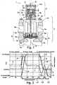
- Fig. 1 shows a longitudinal section through a controllable valve 1 comprising a compressor housing 4 with a suction valve 5 disposed therein, the position of which is influenced by a Abhebegreifer 6, wherein the Abhebegreifer 6 is actuated via a connecting rod designed as a connecting means 7 of a arranged outside the compressor housing 4 control device 2 ,
- the compressor housing 4 comprises a lantern 4a, a gas space 4b, a compression chamber 4c and a lid 4d, wherein the compressor housing 4 also includes a not shown or not visible pressure valve 8, via which the compressed fluid can escape from the compression chamber 4c.
- the automatic suction valve 5 comprises a valve seat 5a, a movably mounted in a stroke direction B, hereinafter also referred to as valve plate 5b Closing member 5b, a valve catch 5c and a return spring 5d.
- the lift-off gripper 6 comprises a plurality of gripper extensions 6a or fingers 6a, a guide 6b and a compression spring 6c.
- the lifting gripper 6, driven by the electromagnets 2a, slidably mounted in the stroke direction B, wherein the tip of the gripper extensions 6a can abut depending on the stroke in direction B on the valve plate 5b, and in particular can press the valve plate 5b against the valve catcher 5c, so that the Valve plate 5b is no longer movable, and the valve 5 thereby forcibly remains open.
- the control device 2 comprises as drive device an electromagnet 2 a with a magnet armature 2 b, a magnetic core 2 c and a magnetic coil 2 d.
- the control device 2 further comprises a housing 2m which is connected to the compressor housing 4 via the connecting part 2e.
- the control device 2 also comprises a drive device 2i or a control device 2i, electrical lines 2k, 21, wherein the electrical line 21 connects the drive device 2i with the solenoid 2a.
- the control device 2 comprises two guides 2f, 2g for slidably supporting the electromagnet 2a and the connecting rod 7 in the stroke direction B.
- a filter 3 may be provided.
- the control device 2 also comprises a displacement sensor 2h, which detects the stroke or the position of the solenoid 2a or the position of the Abhebegreifers 6 in the stroke direction B.
- controllable valve 1 can now be controlled in different ways over the cycles of the crank circuit.
- a cycle is understood to mean a rotation of the crankshaft of the reciprocating compressor through 360 °.
- FIG. 2 shows the method of a continuous backflow control, wherein in FIG. 2 the lifting movement A of the Abhebegreifers 6, the stroke B of the valve plate 5b and the speed C of the Abhebegreifers 6 are shown in function of the crank angle, wherein a single revolution of the crankshaft is shown, that is FIG. 2 shows the course over an angle between 0 ° and 360 °. From the lifting movement B of the valve plate 5b it can be seen that the valve plate 5b automatically opens in the illustrated embodiment in the angular range between about 90 ° and 110 ° during suction, so that the valve plate 5b rests against the valve catch 5c.
- the lifting gripper 6 is moved or moved until it bears against the valve plate 5b. Moreover, in FIG. 2 with the curve C nor the speed of the Abhebegreifers 6 shown. During automatic operation of the suction valve 5, the suction valve 5 would automatically close when reversing the direction of movement of the piston, in the example shown at 225 °.
- stepless backflow control now causes the lift-off gripper 6 abuts the closure member 5b during a first portion K1 of the cycle of the crank circuit and prevents its closure, and that the lift-off gripper 6 during a second portion K2 of the cycle of the crank circle corresponding to the course of the curve A2 is moved back, the closing member 5b, namely the valve plate 5b, due to the applied pressure conditions of the movement of the Abhebegreifers 6 follows or abhebegreifer 6 abuts, so that the valve plate 5b at some point, in the example shown at 290 ° rests on the valve seat 5a and the valve 5 closes.
- the lift-off gripper 6 is still continue to process so that this example is spaced from the valve plate 5b.
- the movement of the closing member 5b is influenced via the drive device, in the illustrated embodiment via the solenoid 2a and the connecting rod 7 in the section K2 such that the Abhebegreifer 6 in function of the crank circle in FIG. 2 illustrated Hubverlauf A or the in FIG. 2 shown speed profile C, wherein the solenoid 2a is controlled such that the speed of the moving closing member 5a is reduced before placing on the suction valve 5, as in FIG. 2 is shown.
- the Abhebegreifer 6 is then moved in a further section K3 still in an end position, as shown in the curve C with the "second hump" by again accelerated and then decelerated again, so that the Abhebegreifer 6, as in the stroke curve A in the section K3 shown, spaced, that is, without direct contact with the closing member 5a, comes to a standstill.
- the electromagnet 2a is controlled in an advantageous method step such that the closing member 5b has a speed of less than 0.1 m / s during placement on the suction valve.
- the valve 1 can also be operated with the method of Aussetzregelung. In the intermittent control of the Abhebegreifer 6 is moved such that it prevents the closing of the closing member 5b during a whole cycle of the crank circuit, preferably in that the Abhebegreifer 6 rests during the entire cycle on the closing member 5b, so that it remains open over the entire cycle.
- FIG. 7 schematically shows a reciprocating compressor comprising a compressor housing 4 with a movably mounted, via a piston rod 4f driven piston 4e, which partially defines a compression chamber 4c.
- a suction valve 5 is also arranged, via which the fluid or gas to be conveyed is sucked.
- the reciprocating compressor also includes a gripper 6, which is driven by a control device 2 comprising a drive device.
- the control device 2 the suction valve 5 and the gripper 6 form a controllable valve 1.
- a pressure valve 8 is also arranged, via which the compressed gas leaves the compression chamber 4c.
- the reciprocating compressor may also comprise a plurality of compression spaces 4c, each compression space 4c comprising a separate piston 4e with piston rod 4f, and each compression space 4c comprising a separate, controllable valve 1.
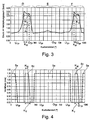
- FIG. 3 shows now the course of the pressure in a compression chamber 4c of a reciprocating compressor in function of the crank angle for different operating methods.
- the bottom dead center U TP is at 90 °, that is, in this position, the compression chamber 4c reaches the maximum volume.
- the top dead center O TP is in this example at 270 °, that is, at this position, the compression chamber 4c reaches the minimum volume.
- the movement of the closing member 5b of the suction valve 5 is carried out automatically, so that over a crank angle of 360 ° the pressure curve shown results.
- the movement of the closing member of the pressure valve 8 takes place in FIG. 3 always automatically.
- the pressure side pressure for example, about 3.1 bar, wherein the pressure valve 8 in the illustrated embodiment, including bias by the Valve springs open at a pressure of about 3.2 bar.
- the pressure valve 8 opens approximately at a crank angle of 190 °.
- the automatic pressure valve 8 is fully opened in the illustrated embodiment during an angular range Kw of about 50 °, because the pressure valve 8 in this Maximaloffenwinkel Scheme Kw has the maximum valve lift before the pressure valve 8 closes again.
- the total opening angle Kv, during which the valve is open, that is, the closing member is lifted from the valve seat, or the entire opening time of the pressure valve 8 is about 80 °.
- a skip control is shown, in which, as described above, the closing member 5b is kept open over the entire crank angle of 360 ° from Abhebegreifer 6, so that results in the compression chamber 4c of the pressure profile shown.
- the pressure in the compression chamber 4c is constantly below 3.2 bar, so that the pressure valve 8 does not open automatically.
- a continuous backflow control is shown, in which, as in FIG. 2 described, the closing member 5b is kept open during part of the crank angle of 360 ° from Abhebegreifer 6, so that the pressure build-up in the compression chamber 4c based on the crank angle takes place later, and the pressure curve shown results.
- the pressure valve 8 opens approximately at a crank angle of 210 °.
- the automatic pressure valve 8 remains fully open in the illustrated embodiment during a Maximaloffenwinkel Scheme Kw of about 30 ° before the valve lift, as in FIG. 4 shown reduced, and the valve 8 completely closes again after the total opening angle Kv.
- the total opening angle Kv, during which the valve 8 is open, or the total opening time of the valve is about 60 °.
- the closing element 5b of the suction valve 5 is pressed on only at the beginning of the compression phase. As a result, a portion of the gas is forced back into the suction line. Closes the suction valve 5, the remaining gas can be compressed in the compression chamber and pressed by the pressure valve in the pressure line.
- the compression chamber promotes only part of the maximum possible gas flow.
- Both methods use the lift-off gripper 6 to push the sealing element 5b of the valve 5, for example a plate, ring or poppet valve, against the valve catcher 5c and thus into the open position. Since in the continuous feedback control of the Abhebegreifer 6 must be moved in a work cycle from the closed to the open position and back, and there is a longer time available in the Aussetzregelung for the same sequence of movements, the power consumption, the required forces, the speeds and the stress of the components used in the continuous backflow control higher.
- the flow rate of a reciprocating compressor can now, as in FIG. 3 indicated by a combination of stepless backflow control F and Aussetzregelung E are regulated in a wide range, in addition also the portion D can be used for flow control, during which the closing member 5b moves automatically.
- These three types of operation D, E, F of operating the valve 5 can now be combined with each other, so that, for example, during successive cycles initially only the type of operation D, E or F takes place, and later, for example, a combination of at least two of the three types of operation D, E and F.
- the valve could for example be controlled such that different flow rates are controlled so that the suction valve 5 is automatically operated at high flow rates during certain cycles, and is operated during certain cycles according to the continuous backflow control, that the suction valve 5 is operated at medium flow rates during each cycle according to the continuous backflow control, and that the suction valve 5 is constantly kept open at low flow rates during certain cycles, and is operated during certain cycles according to the stepless backflow control.
- FIG. 4 shows the lifting movement 8c of the pressure valve 8 in function of the crankshaft angle.
- the lifting movement 5e of the closing member 5b of the suction valve 5 is shown as a function of the crankshaft angle.
- the movement of the pressure valve 8 takes place automatically, whereas the movement of the closing member 5b of the suction valve 5 as described above in the Aussetzregelung E and the backflow control F is determined by the gripper 6.
- the maximum open angle range Kw within which the valve 8 has a maximum valve lift, that is, maximum is open.
- the total opening angle Kv can be seen, during which the valve 8 is opened.
- the opening duration of the automatic pressure valve 8 is determined by the angular range during which the pressure in the compression chamber 4c is above the opening pressure of the pressure valve 8, according to the exemplary embodiment FIG. 3 above a pressure of 3.2 bar. From the in FIGS. 3 and 4 shown with F continuous backflow control can be seen that the angular range of the open pressure valve 8 is reduced, the later the closing member 5b is closed. This has the consequence, in particular for small flow rates, that the pressure valve 8 would only be opened during a very short total opening angle Kv if the backflow control were used continuously.
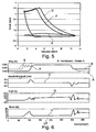
- FIG. 5 shows a load curve in a PV diagram in different operating methods, namely as already in FIG. 3 shown, at full load D with automatic suction valve 5, in the Aussetzregelung E and in the continuous flow control F.
- a compressor may be configured such that it as in FIG. 7 represented per cylinder only one compression space 4c, wherein such a compression space 4c is also referred to below as the upper compression space.
- the compressor may also be designed such that it has a second compression chamber in the same cylinder, which is separated from the first compression chamber by the piston 4e, so that during the movement of the piston 4e the fluid is compressed in one compression chamber and drawn in the other compression chamber.
- the second compression space is also referred to below as the lower compression space.
- the flow rate control takes place as in FIG.
- the opening time of the pressure valve 8 can be determined, for example, by measuring the pressure in the compression chamber and comparing it with the final pressure, or by knowing the operating cases of the compressor via a previous, respectively simultaneous calculation of the maximum opening time of the suction valve over the reversal point of the movement of the piston. so that the minimum opening time of the pressure valve is not undershot.
- FIG. 6 shows characteristic variables of the controllable valve 1 as a function of the crank angle or the angle of rotation to the in FIG. 6 in the path diagram shown movement curve B of the valve plate 5b and the course of motion A of the lift-off gripper 6 to obtain.
- the curve C the speed profile of the lift-off gripper 6 is shown.
- the force G caused by the electromagnet 2a and the current H required for driving the electromagnet 2a are shown.
- Processes shown are particularly important to the in FIG. 2 shown, "gentle landing" of the valve plate 5b on the valve catch 5c to effect.
- FIG. 8 schematically shows a further embodiment of a control device 2 for actuating and driving the force acting on the suction valve 5 gripper 6.
- the control device 2 comprises a drive device 2n, which via the linearly movably mounted connecting rod 7 with the in FIG. 7 schematically illustrated gripper 6 is connected.
- the drive device 2n shown in this embodiment comprises a linear drive 2w and an electrically controllable damping device 2o, wherein the damping device 2o has the function of the electrically driven to dampen the movement generated by the linear drive 2w so that the gripper 6 and the valve plate 5b of the suction valve 5 as for example in FIG. 2 shown moves.
- the linear drive 2w has a linearly movable connecting rod 2t, which is operatively connected to the connecting rod 7.
- the damping device 2o is disposed between the linear drive 2w and the gripper 6.
- the damping device 2o could also be arranged at a different location, in the illustrated view of the control device. 2 for example, above the linear drive 2w.
- the damping device 2o can be configured in a variety of ways to effect a damping of the movement of the linear drive 2w.
- "soft landing" of the valve plate 5b on the valve catcher 5c is the in FIG. 8 schematically illustrated damping device 2o particularly advantageous.
- the damping device 2o comprises a cylinder 2p and in its interior a linearly displaceable piston 2r which divides the interior of the cylinder 2p into a first inner space 2q and a second inner space 2s.
- the two inner spaces 2q, 2s are connected to each other via a fluid-conducting connection 2u, so that a fluid is exchangeable between the two inner spaces 2q, 2s.
- the two inner spaces 2q, 2s are conductively connected to each other via an electrically controllable damping or throttle 2v fluid.
- a drive and control device 2i is electrically connected via electrical lines 2k, 21 signal to the linear drive 2w and the controllable damping 2v, so that both the linear drive 2w and the damping properties of the damping device 2o are controlled to the position or the speed of the valve plate 5b such that, as in FIG. 2 exemplified a "gentle landing" of the valve plate 5b is effected.
- the fluid-conducting connection 2u and the electrically controllable damping 2v could also be arranged on the damping device 2o or within the damping device 2o, in particular also on the piston 2r in that the piston 2r has, for example, a fluid-conducting connection between the first and second internal spaces 2q, 2s ,
- the fluid of the damping device 2o at least partially consists of an electrorheological or magnetorheological fluid.
- Such liquids have the property that their viscosity is electrically controllable, so that with such liquids ein.elektrisch controllable throttle section can be configured.
- Such a throttle section has the advantage that the viscosity can be varied within a wide range, and that the viscosity can be changed very quickly with the aid of the electrical signal.
- damping properties of such a damping device 2o are characterized very quickly changed, so that the movement of the piston 2r and thus the movement of the connecting rod 7, the gripper 6 and ultimately the valve plate 5b can be so damped or controlled and controlled, the valve plate 5b with respect Edinburghirk and speed performs a "gentle landing".
- Damping devices comprising an electrorheological or magnetorheological fluid are known, for example, from the document WO2008 / 141787A1 or from the publication EP 1034383B1 known.
- the linear drive 2w can be designed, for example, as a hydraulic or pneumatic drive, as an electromagnetic drive, as a linear motor or as an electric motor with a translation.
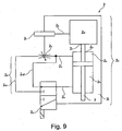
- FIG. 9 shows a further embodiment of a control device 2.
- the damping device 2o according to FIG. 9 an electrically controllable three-way valve 2y, a non-variable throttle 2x and fluid lines 2u 1 and 2u 2nd
- the damping properties of Damping device 2o can be controlled via the electrical three-way valve 2y by allowing the fluid exchanged between the first and second internal spaces 2q, 2s to flow either via the fluid line 2u 2 or the fluid line 2u 1 and the throttle 2 x.
- the damping device 20o could also comprise a plurality of throttles 2 x with different throttling effects, as well as a multi-way valve which can controllably and selectively supply the fluid to each of these throttles, so that the damping device 2 o has a plurality of different dampings.
- the damping device 2o could also be configured such that the braking energy output by the damping device 20o to the closing member 5b can be recovered.
- the damping device 2o could for example be designed as an eddy current brake.
- the damping properties of such an eddy current brake could also be electrically controlled.
- the damping device 2o is thus designed as a controllable eddy current brake, which on the one hand allows controlling the damping properties and which on the other hand allows energy recovery, wherein in the energy recovery preferably electrical energy is generated.
- a damping device 2o with energy recovery is particularly advantageous to the total energy required to operate the suction valve 5 and to operate the Abhebegreifers 6 to reduce.
- the heating occurring during operation is also reduced.
- control device 2 comprises an adaptive pilot control with which the stroke A and the speed C of the lift-off gripper 6 are regulated.
Landscapes
- Engineering & Computer Science (AREA)
- Mechanical Engineering (AREA)
- General Engineering & Computer Science (AREA)
- Compressor (AREA)
Description
- Die Erfindung betrifft ein Verfahren zur Fördermengenregelung eines Hubkolben-Kompressors gemäss dem Oberbegriff von Anspruch 1. Die Erfindung betrifft weiter einen Hubkolben-Kompressor mit Fördermengenregelung gemäss dem Oberbegriff von Anspruch 11.
- Die Druckschriften
EP 0801227 A2 ,WO 2008/000 698 A2 undEP1400692 offenbaren ein Verfahren zur Beeinflussung der druckabhängig selbsttätigen, periodischen Öffnungsbewegung eines Schließorganes eines Saugventils eines Hubkolben-Kompressors mittels einer, bedarfaweise zumindest über einen Teil des Kurbelkreises auf das Schließorgan einwirkenden Steuereinrichtung. Da die Lebensdauer von zumeist saug- und druckseitig verwendeten, selbsttätigen Kompressorventilen primär durch die Schlagbeanspruchung beim abwechselnden Auftreffen des eigentlichen Schließorganes auf Sitz bzw. Fänger beeinflusst wird, offenbart die genannte Druckschrift ein Verfahren, bei welchem das Saugventil mittels eines sogenannten Abhebegreifers vor Erreichen des Druckgleichgewichtes zwangsweise geöffnet wird, um eine starke momentane Beschleunigung des Schliessorgans in Richtung zum Fänger hin, welche beim selbsttätigen Öffnen auftreten würde, zu vermeiden. Dies ermöglicht die Schlagbeanspruchung des Kompressorventils zu reduzieren. - Dieses Verfahren weist den Nachteil auf, dass die saug- und insbesondere die druckseitig verwendeten Kompressorventile immer noch eine hohe Beanspruchung aufweisen, insbesondere dann, wenn die Kompressoranlage gemäss dem Verfahren einer stufenlosen Rückstromregelung betrieben wird. Bei der stufenlosen Rückstromregelung wird das Saugventil mit Hilfe des Abhebegreifers während eines Teilwinkelbereichs des Kompressionstaktes offen gehalten und danach geschlossen, um dadurch die Fördermenge zu beeinflussen. Ein Nachteil dieses bekannten Verfahrens ist die Tatsache, dass das Schliessorgan des Saugventils und des Druckventils einem relativ grossen Verschleiss unterliegt, was einen entsprechend hohen Wartungsaufwand erfordert.
- Aufgabe der Erfindung ist es ein vorteilhafteres Verfahren zur Fördermengenregelung eines Hubkolben-Kompressors zu bilden. Diese Aufgabe wird gelöst mit einem Verfahren aufweisend die Merkmale von Anspruch 1. Die abhängigen Ansprüche 2 bis 10 betreffen weitere, vorteilhafte Verfahrensschritte. Die Aufgabe wird weiter gelöst mit einem Hubkolben-Kompressor aufweisend die Merkmale von Anspruch 11. Die abhängigen Ansprüche 12 bis 15 betreffen weitere, vorteilhafte Ausführungsformen.
- Die Aufgabe wird insbesondere gelöst mit einem Verfahren zur Fördermengenregelung eines Hubkolben-Kompressors, indem die Bewegung eines Schliessorgans eines selbsttätigen Saugventils mittels eines von einer Steuereinrichtung angetriebenen Abhebegreifers während zumindest eines Teils eines Zyklus des Kurbelkreises beeinflusst wird, wobei das Verfahren eine stufenlose Rückstromregelung umfasst, bei welcher der Abhebegreifer während eines ersten Teilabschnittes des Zyklus des Kurbelkreises am Schliessorgan anliegt und dessen Schliessen verhindert, und bei welcher der Abhebegreifer während eines zweiten Teilabschnittes des Zyklus des Kurbelkreises zurückgefahren wird und das Schliessorgan geschlossen wird, wobei der Abhebegreifer derart zurückgefahren wird, dass die Geschwindigkeit des sich bewegenden Schliessorgans vor dem Aufsetzen auf das Saugventil reduziert wird.
- In einem weiteren vorteilhaften Verfahren umfasst dieses eine Aussetzregelung, bei welcher der Abhebegreifer während eines ganzen Zyklus des Kurbelkreises das Schliessen des Schliessorgans verhindert, wobei die Fördermenge zumindest durch eine Kombination von stufenloser Rückstromregelung und Aussetzregelung geregelt wird.
- Beim erfindungsgemässen Verfahren wird die Fördermenge durch das erzwungene Offenhalten des Saugventils geregelt. Dabei werden zur Regelung vorzugsweise zwei unterschiedliche Verfahren verwendet, nämlich eine Aussetzregelung und die stufenlose Rückstromregelung. Beide Verfahren verwenden einen sogenannten Abhebegreifer, welcher das Schliessorgan des Ventils, zum Beispiel ein Platten-, Ring- oder Poppetventil, in eine offene Stellung drücken, und vorzugsweise auf den Ventilsitz drücken.
- Der Hubkolben-Kompressor weist einen Verdichtungsraum auf, welchem über ein Saugventil Gas zugeführt wird, und aus welchem über ein Auslassventil, auch als Druckventil bezeichnet, verdichtetes Gas abgeführt wird. Beim Verfahren der Aussetzregelung wird das Schliessorgan des Saugventils während eines gesamten Arbeitstakts beziehungsweise eines ganzen Arbeitszyklus offen gehalten. Dadurch steigt während der Kompressionsphase der Druck im Verdichtungsraumes nicht über den Druck an, welcher erforderlich ist um das Druckventil zu öffnen, sodass das angesaugte Gas während der Kompressionsphase zurück in die Saugleitung gedrückt wird, und dadurch der Verdichtung und dem Weitertransport in die Druckleitung nicht zur Verfügung steht. Das Druckventil bleibt somit geschlossen und dieser Verdichtungsraum fördert somit kein Gas über das Druckventil in die Druckleitung. Wird die Aussetzregelung deaktiviert, das heisst ein Normalbetrieb gefahren, so fördert der Verdichtungsraum wieder den gesamten Gasstrom über das Druckventil in die Druckleitung. Weist der Hubkolben-Kompressor beispielsweise nur einen Verdichtungsraum auf, so kann die Aussetzregelung derart betrieben werden, dass gewisse Arbeitszyklen mit Normalbetrieb gefahren werden, und während gewissen Arbeitszyklen die Aussetzregelung aktiviert ist. Ein Nachteil der Aussetzregelung ist somit, dass die vom Hubkolben-Kompressor geförderte Gasmenge nur stufenweise reguliert werden kann. Ein weiterer Nachteil der Aussetzregelung ist, dass der entlastete Verdichtungsraum, das heisst bei sich nicht öffnendem Druckventil, nicht durchströmt wird und sich dadurch Schmutz im Verdichtungsraum ansammeln kann, welcher den Verschleiss der Ventile respektive der Packungsringe und Kolbenringe erhöht.
- Beim Verfahren der Rückstromregelung wird das Saugventil mit Hilfe des Abhebegreifers während eines Teilwinkelbereichs eines vollständigen Kompressionstaktes beziehungsweise eines vollständigen Kurbelkreises offen gehalten und danach geschlossen, um dadurch die Fördermenge zu beeinflussen. Dabei wird das Saugventil nur zu Beginn der Kompressionsphase durch den Abhebegreifer aufgedrückt. Dadurch wird ein Teil des sich im Verdichtungsraum befindlichen Gases zurück in die Saugleitung gedrückt. Sobald das Schliessorgan des Saugventils vollständig schliesst wird das im Verdichtungsraum verbliebene Gas komprimiert und über das Druckventil in die Druckleitung gepresst. Während der Rückstromregelung wird somit nur einen Teil des maximal möglichen Gasstroms aus dem Verdichtungsraum über das Druckventil in die Druckleitung gefördert.
- Nachteilig am Verfahren der Rückstromregelung ist die Tatsache, dass die Öffnungszeit des selbsttätigen Druckventils bei kleineren Fördermengen entsprechend reduziert wird, und dass bei Fördermengen geringer als 40% der nominalen Fördermenge die Öffnungszeit des Druckventils derart verkürzt wird, dass sich die Öffnungs- und Schliessgeschwindigkeiten des Druckventils vervielfachen können. Dies führt einerseits zu einem erhöhten Verschleiss des selbsttätigen Druckventils, und andererseits reduziert dies den Bereich innerhalb welchem Teilfördermengen zuverlässig geförderte werden können. Ein weiterer Nachteil der Rückstromregelung ist, dass das Gas vor dem Verdichten stärker erwärmt wird auf Grund der längeren Verweilzeit im Verdichtungsraum und auf Grund des Wärmetransfers über die Zylinderwand und auf Grund eines Leckagestroms über den Kolben. Dies hat zur Folgen, dass das Gas auf der Druckseite eine erhöhte Temperatur aufweist.
- Das erfindungsgemässe Verfahren weist in einer vorteilhaften Ausgestaltung den Vorteil auf, dass durch die kombinierte Anwendung von Rückstromregelung und Aussetzregelung die vom Hubkolben-Kompressor geförderte Menge in einem weiten Bereich verändert werden kann, insbesondere ohne zusätzlichen Verschleiss des Schliessorgans des Saugventils und/oder des Druckventils. Für die Regelung der Fördermenge stehen vorzugsweise im Wesentlichen drei unterschiedliche Verfahren zur Verfügung, welche angewendet werden können. Nebst einem Verfahren mit maximaler Fördermenge, bei welche das Saugventil selbsttätig schliesst, noch das bereits beschriebene Verfahren der Rückstromregelung und das bereits beschriebene Verfahren der Aussetzregelung. Abhängig von der jeweils zu fördernden Fluidmenge kann die Regelung beispielsweise wie folgt erfolgen:
- Zum Fördern der maximalen Fördermenge wird das Saugventil nicht beeinflusst und öffnet und schliesst somit selbsttätig.
- Bei grossen Förderströmen, das heisst Fördermengen im Bereich zwischen etwa 100% und 80% der maximalen Fördermenge, wird eine stufenlose Rückstromregelung eingesetzt. Wobei es auch möglich ist, dass nicht jeder Zyklus des Kurbelkreises mit der Rückstromregelung geregelt wird, sondern das Saugventil auch beispielsweise einen oder zwei Zyklen selbsttätig und somit ohne Beeinflussung betrieben wird. Dieses Verfahren weist den Vorteil auf, dass der Abhebegreifer weniger beansprucht wird, sodass sich längere Standzeiten ergeben, und dass die Mengenregelung selbst weniger Energie verbraucht.
- Bei mittleren Förderströmen, das heisst bei Fördermengen im Bereich zwischen etwa 80% und 50% der maximalen Fördermenge, wird bei jedem Zyklus die stufenlose Rückstromregelung verwendet.
- Bei kleinen Förderströmen, das heisst bei Fördermengen im Bereich zwischen etwa 50% und 0% der maximalen Fördermenge, wird das Schliessorgan des Saugventils Mittels der Aussetzregelung während beispielsweise einem oder zwei Zyklen offengehalten. Bei den anderen Zyklen kann entweder das Saugventil selbsttätig betrieben werden, oder zusätzlich, falls erforderlich, die Rückstromregelung eingesetzt werden.
- Besonders vorteilhaft wird das Saugventil durch die Steuereinrichtung und den Abhebegreifer derart beeinflusst, dass das Schliessorgan des Druckventils des Hubkolben-Kompressors zumindest während eines vorgegebenen Öffnungswinkelbereichs eines Kurbelkreises geöffnet wird. Der Öffnungswinkelbereich beträgt zumindest 10° und vorzugsweise zumindest 20° bis 30°.
- Das erfindungsgemässe Verfahren sowie der erfindungsgemässe Hubkolbenkompressor weisen den Vorteil auf, dass die Hubbewegung und/oder die Geschwindigkeit des Abhebegreifers mit Hilfe einer Antriebsvorrichtung, vorzugsweise einen Elektromagneten, sehr präzise ansteuerbar ist, derart, dass die Geschwindigkeit des sich schliessenden Schliessorgans vor dem Aufsetzen auf das Saugventil reduziert werden kann, sodass das Schliessorgan mit geringer Geschwindigkeit am Saugventil auftrifft und dort zu liegen kommt, sodass das Schliessorgan somit "sanft" auf das Saugventil aufsetzt, was auf Englisch auch als "soft landing" bezeichnet werden kann. In einem besonders bevorzugten Verfahren beträgt die Geschwindigkeit des Schliessorgans während des Aufsetzens auf das Saugventil weniger als 0,1 m/ s, sodass das Schliessorgan 5b während dem Auftreffen auf den Ventilsitz 5a des Saugventils 5 eine Grenzauftreffgeschwindigkeit von weniger als 0,1 m/s aufweist. Dieses vorteilhafte Verfahren reduziert den Verschleiss des Schliessorganes erheblich und hat vorteilhafter zusätzlich zur Folge, dass der Betrieb des Ventils einen geringeren Geräuschpegel aufweist.
- In einer weiteren vorteilhaften Ausgestaltung umfasst die Antriebsvorrichtung eine ansteuerbare Dämpfungsvorrichtung, um die Geschwindigkeit des Abhebegreifers und insbesondere auch den Ort der reduzierten Geschwindigkeit derart zu beeinflussen, dass das Schliessorgan beim Schliessen mit geringer Geschwindigkeit am Saugventil auftrifft, sodass das Schliessorgan somit "sanft" auf das Saugventil aufsetzt und dieses schliesst. Die Dämpfungsvorrichtung ist besonders vorteilhaft elektrisch ansteuerbar, und umfasst besonders vorteilhaft eine elektrorheologische oder magnetorheologische Flüssigkeit, deren Viskosität elektrostatisch oder elektromagnetisch veränderbar ist, sodass die Dämpfung über elektrische Signale sehr schnell veränderbar ist. Die Dämpfungsvorrichtung kann jedoch auch auf einem anderen Prinzip beruhen und beispielsweise als Elektromagnet ausgestaltet sein.
- Die Erfindung wird nachfolgend mit Hilfe von Ausführungsbeispielen im Detail beschrieben.
- Die zur Erläuterung der Ausführungsbeispiele verwendeten Zeichnungen zeigen:
- Fig. 1
- einen Längsschnitt durch ein ansteuerbares Ventil;
- Fig. 2
- ein Beispiel der Bewegung des Abhebegreifers, des Schliessorgans des Saugventils sowie der Geschwindigkeit des Abhebegreifers in Funktion des Kurbelwinkels;
- Fig. 3
- der Verlauf des Drucks im Verdichtungsraum des Hubkolbenkompressors bei unterschiedlichen Betriebsverfahren;
- Fig. 4
- der Verlauf des Ventilhubs des Saugventils und des Druckventils bei den in
Figur 3 dargestellten Betriebsverfahren; - Fig. 5
- ein Lastverlauf in einem PV-Diagramm bei unterschiedlichen Betriebsverfahren;
- Fig. 6
- charakteristische Grössen des Ventils in Funktion des Kurbelwinkels;
- Fig. 7
- schematisch ein Hubkolben-Kompressor;
- Fig. 8
- schematisch eine Steuereinrichtung zum Betätigen des auf das Saugventil wirkenden Greifers;
- Fig. 9
- schematisch eine weitere Steuereinrichtung zum Betätigen des auf das Saugventil wirkenden Greifers.
- Grundsätzlich sind in den Zeichnungen gleiche Teile mit gleichen Bezugszeichen versehen.
-
Fig. 1 zeigt einen Längsschnitt durch ein ansteuerbares Ventil 1 umfassend ein Kompressorgehäuse 4 mit einem darin angeordneten Saugventil 5, dessen Stellung von einem Abhebegreifer 6 beeinflusst wird, wobei der Abhebegreifer 6 über ein als Verbindungsstange ausgestaltetes Verbindungsmittel 7 von einer ausserhalb des Kompressorgehäuses 4 angeordneten Steuereinrichtung 2 betätigt wird. Das Kompressorgehäuse 4 umfasst eine Laterne 4a, einen Gasraum 4b, einen Verdichtungsraum 4c und einen Deckel 4d, wobei das Kompressorgehäuse 4 zudem ein nicht dargestelltes beziehungsweise nicht sichtbares Druckventil 8 umfasst, über welches das komprimierte Fluid aus dem Verdichtungsraum 4c entweichen kann. Das selbsttätige Saugventil 5 umfasst einen Ventilsitz 5a, ein in einer Hubrichtung B beweglich gelagertes, nachfolgend auch als Ventilplatte 5b bezeichnetes Schliessorgan 5b, einen Ventilfänger 5c sowie eine Rückstellfeder 5d. Der Abhebegreifer 6 umfasst eine Mehrzahl von Greiferfortsätzen 6a oder Fingern 6a, eine Führung 6b sowie eine Druckfeder 6c. Der Abhebegreifer 6 ist, angetrieben von den Elektromagneten 2a, in Hubrichtung B verschiebbar gelagert, wobei die Spitze der Greiferfortsätze 6a abhängig vom Hub in Richtung B an der Ventilplatte 5b anliegen können, und insbesondere die Ventilplatte 5b gegen den Ventilfänger 5c drücken können, sodass die Ventilplatte 5b nicht mehr beweglich ist, und das Ventil 5 dadurch zwangsweise geöffnet bleibt. Die Steuereinrichtung 2 umfasst als Antriebsvorrichtung einen Elektromagnet 2a mit einem Magnetanker 2b, einem Magnetkern 2c sowie einer Magnetspule 2d. Die Steuereinrichtung 2 umfasst weiter ein Gehäuse 2m, das über das Verbindungsteil 2e mit dem Kompressorgehäuse 4 verbunden ist. Die Steuereinrichtung 2 umfasst zudem eine Ansteuervorrichtung 2i oder eine Regelvorrichtung 2i, elektrische Leitungen 2k, 21, wobei die elektrische Leitung 21 die Ansteuervorrichtung 2i mit dem Elektromagnet 2a verbindet. Die Steuereinrichtung 2 umfasst zwei Führungen 2f, 2g um den Elektromagnet 2a und die Verbindungsstange 7 in Hubrichtung B verschiebbar zu lagern. Zudem kann noch ein Filter 3 vorgesehen sein. In einer vorteilhaften Ausgestaltung umfasst die Steuereinrichtung 2 zudem einen Wegsensor 2h, welcher den Hub beziehungsweise die Lage des Elektromagnet 2a beziehungsweise die Lage des Abhebegreifers 6 in Hubrichtung B erfasst. - Das in
Figur 1 dargestellte ansteuerbare Ventil 1 kann nun über die Zyklen des Kurbelkreises auf unterschiedliche Weise angesteuert werden. Unter einem Zyklus wird eine Drehung der Kurbelwelle des Hubkolben-Kompressors um 360° verstanden. -
Figur 2 zeigt das Verfahren einer stufenlosen Rückstromregelung, wobei inFigur 2 die Hubbewegung A des Abhebegreifers 6, die Hubbewegung B der Ventilplatte 5b und die Geschwindigkeit C des Abhebegreifers 6 in Funktion des Kurbelwinkels dargestellt sind, wobei eine einzige Umdrehung der Kurbelwelle dargestellt ist, das heisstFigur 2 zeigt den Verlauf über einem Winkel zwischen 0° und 360°. Aus der Hubbewegung B der Ventilplatte 5b ist ersichtlich, dass sich die Ventilplatte 5b während dem Ansaugen, im dargestellten Ausführungsbeispiel im Winkelbereich zwischen etwa 90° und 110° selbsttätig öffnet, sodass die Ventilplatte 5b am Ventilfänger 5c anliegt. Beim Verfahren der stufenlosen Rückstromregelung wird nach dem Öffnen der Ventilplatte 5b, wie mit der Kurve A beispielhaft dargestellt, der Abhebegreifer 6 bewegt beziehungsweise verfahren, bis dieser an der Ventilplatte 5b anliegt. Zudem ist inFigur 2 mit der Kurve C noch die Geschwindigkeit des Abhebegreifers 6 dargestellt. Beim selbsttätigen Betrieb des Saugventils 5 würde das Saugventil 5 bei Umkehr der Bewegungsrichtung des Kolbens, im dargestellten Beispiel bei 225°, selbsttätig schliessen. Das Verfahren der stufenlosen Rückstromregelung bewirkt nun, dass der Abhebegreifer 6 während eines ersten Teilabschnittes K1 des Zyklus des Kurbelkreises am Schliessorgan 5b anliegt und dessen Schliessen verhindert, und dass der Abhebegreifer 6 während eines zweiten Teilabschnittes K2 des Zyklus des Kurbelkreises entsprechend dem Verlauf der Kurve A2 zurückgefahren wird, wobei das Schliessorgan 5b, nämlich die Ventilplatte 5b, auf Grund der anliegenden Druckverhältnisse der Bewegung des Abhebegreifers 6 folgt beziehungsweise am Abhebegreifer 6 anliegt, sodass die Ventilplatte 5b irgendwann, im dargestellten Beispiel etwa bei 290°, auf dem Ventilsitz 5a aufliegt und das Ventil 5 verschliesst. Im weiteren Teilabschnitt K3 wird der Abhebegreifer 6 noch weiter verfahren, damit dieser z.B. von der Ventilplatte 5b beabstandet ist. - Die Bewegung des Schliessorgans 5b wird über die Antriebsvorrichtung, im dargestellten Ausführungsbeispiel über den Elektromagnet 2a und die Verbindungsstange 7 im Teilabschnitt K2 derart beeinflusst, dass der Abhebegreifer 6 in Funktion des Kurbelkreises den in
Figur 2 dargestellten Hubverlauf A beziehungsweise den inFigur 2 dargestellten Geschwindigkeitsverlauf C aufweist, wobei der Elektromagnet 2a derart angesteuert wird, dass die Geschwindigkeit des sich bewegenden Schliessorgans 5a vor dem Aufsetzen auf das Saugventil 5 reduziert wird, wie dies inFigur 2 dargestellt ist. Erfindungsgemäß wird der Abhebegreifer 6 danach in einem weiteren Teilabschnitt K3 noch in eine Endlage verfahren, wie in der Kurve C mit dem "zweiten Höcker" dargestellt, indem nochmals beschleunigt und danach wieder abgebremst wird, sodass der Abhebegreifer 6, wie im Hubverlauf A im Teilabschnitt K3 dargestellt, beabstandet, das heisst ohne direkten Kontakt mit dem Schliessorgan 5a, zum Stillstand gelangt. Der Elektromagnet 2a wird in einem vorteilhaften Verfahrensschritt derart angesteuert, dass das Schliessorgan 5b während des Aufsetzens auf das Saugventil eine Geschwindigkeit von weniger als 0,1 m/s aufweist. - Das Ventil 1 kann auch mit dem Verfahren der Aussetzregelung betrieben werden. Bei der Aussetzregelung wird der Abhebegreifer 6 derart verfahren, dass dieser während eines ganzen Zyklus des Kurbelkreises das Schliessen des Schliessorgans 5b verhindert, vorzugsweise dadurch, dass der Abhebegreifer 6 während dem ganzen Zyklus am Schliessorgan 5b anliegt, sodass dieses über den ganzen Zyklus geöffnet bleibt.
-
Figur 7 zeigt schematisch einen Hubkolbenkompressor umfassend ein Kompressorgehäuse 4 mit einem beweglich gelagerten, über eine Kolbenstange 4f angetriebenen Kolben 4e, der teilweise einen Verdichtungsraum 4c begrenzt. Am Kompressorgehäuse 4 ist zudem ein Saugventil 5 angeordnet, über welches das zu fördernde Fluid oder Gas angesogen wird. Der Hubkolbenkompressor umfasst zudem einen Greifer 6, der von einer Steuereinrichtung 2 umfassend eine Antriebsvorrichtung angetrieben ist. Die Steuereinrichtung 2, das Saugventil 5 und der Greifer 6 bilden ein ansteuerbares Ventil 1. Am Kompressorgehäuse 4 ist zudem ein Druckventil 8 angeordnet, über welches das komprimierte Gas den Verdichtungsraum 4c verlässt. Der Hubkolbenkompressor kann natürlich auch eine Mehrzahl von Verdichtungsräumen 4c umfassen, wobei jeder Verdichtungsraum 4c einen separaten Kolben 4e mit Kolbenstange 4f umfasst, und wobei jeder Verdichtungsraum 4c ein separates, ansteuerbares Ventil 1 umfasst. -
Figur 3 zeigt nun den Verlauf des Drucks in einem Verdichtungsraum 4c eines Hubkolbenkompressors in Funktion des Kurbelwinkels für unterschiedliche Betriebsverfahren. Im dargestellten Ausführungsbeispiel liegt der untere Totpunkt UTP bei 90°, das heisst bei dieser Stellung erreicht der Verdichtungsraum 4c das maximale Volumen. Der obere Totpunkt OTP liegt in diesem Beispiel bei 270°, das heisst bei dieser Stellung erreicht der Verdichtungsraum 4c das minimale Volumen. Im ersten Abschnitt D erfolgt die Bewegung des Schliessorgans 5b des Saugventils 5 selbsttätig, sodass sich über einen Kurbelwinkel von 360° der dargestellte Druckverlauf ergibt. Die Bewegung des Schliessorgans des Druckventils 8 erfolgt inFigur 3 immer selbsttätig. Im dargestellten Ausführungsbeispiel beträgt der druckseitig Druck beispielsweise etwa 3.1 Bar, wobei das Druckventil 8 im dargestellten Ausführungsbeispiel inklusive Vorspannung durch die Ventilfedern sich bei einem Druck von etwa 3,2 Bar öffnet. Das Druckventil 8 öffnet etwa bei einem Kurbelwinkel von 190°. Das selbsttätige Druckventil 8 ist im dargestellten Ausführungsbeispiel während einem Winkelbereich Kw von etwa 50° vollständig geöffnet, weil das Druckventil 8 in diesem Maximaloffenwinkelbereich Kw den maximalen Ventilhub aufweist, bevor das Druckventil 8 wieder schliesst. Der Gesamtöffnungswinkel Kv, während welchem das Ventil geöffnet ist, das heisst das Schliessorgan vom Ventilsitz abgehoben ist, beziehungsweise die gesamte Öffnungszeit des Druckventils 8 beträgt ca. 80°. Im zweiten Abschnitt E ist eine Aussetzregelung dargestellt, bei welcher wie vorhin beschrieben das Schliessorgans 5b über den gesamten Kurbelwinkel von 360° vom Abhebegreifer 6 offen gehalten wird, sodass sich im Verdichtungsraum 4c der dargestellte Druckverlauf ergibt. Der Druck im Verdichtungsraum 4c bleibt ständig unter 3,2 Bar, sodass sich das Druckventil 8 nicht selbsttätig öffnet. Im dritten Abschnitt F ist eine stufenlose Rückstromregelung dargestellt, bei welcher, wie inFigur 2 beschrieben, das Schliessorgans 5b während eines Teils des Kurbelwinkel von 360° vom Abhebegreifer 6 offen gehalten wird, sodass der Druckaufbau im Verdichtungsraum 4c bezogen auf den Kurbelwinkel später erfolgt, und sich der dargestellte Druckverlauf ergibt. Das Druckventil 8 öffnet etwa bei einem Kurbelwinkel von 210°. Das selbsttätige Druckventil 8 bleibt im dargestellten Ausführungsbeispiel während einem Maximaloffenwinkelbereich Kw von etwa 30° vollständig geöffnet, bevor sich der Ventilhub, wie inFigur 4 dargestellt verringert, und das Ventil 8 nach dem Gesamtöffnungswinkel Kv wieder vollständig schliesst. Der Gesamtöffnungswinkel Kv, während welchem das Ventil 8 geöffnet ist, beziehungsweise die gesamte Öffnungszeit des Ventils beträgt ca. 60°. - Bei der Aussetzregelung wird somit während eines gesamten Arbeitstakts das Saugventil 5 offen gehalten. Dadurch wird während der Kompressionsphase das angesaugte Gas zurück in die Saugleitung gedrückt und steht somit der Verdichtung und dem Weitertransport in die Druckleitung nicht zur Verfügung. Der Verdichtungsraum fördert kein Gas. Wird die Aussetzregelung deaktiviert fördert der Verdichtungsraum wieder den vollen Fluidstrom.
- Bei der stufenlosen Rückstromregelung hingegen wird nur zu Beginn der Kompressionsphase das Schliessorgan 5b des Saugventils 5 aufgedrückt. Dadurch wird ein Teil des Gases zurück in die Saugleitung gedrückt. Schliesst das Saugventil 5, so kann das verbliebene Gas im Verdichtungsraum komprimiert werden und durch das Druckventil in die Druckleitung gepresst werden. Der Verdichtungsraum fördert nur einen Teil des maximal möglichen Gasstroms.
- Beide Verfahren verwenden den Abhebegreifer 6 um das Dichtelement 5b des Ventils 5, zum Beispiel ein Platten-, Ring- oder Poppetventil, gegen den Ventilfänger 5c und somit in die offene Stellung zu drücken. Da bei der stufenlosen Rückstromregelung der Abhebegreifer 6 in einem Arbeitszyklus von der geschlossenen in die offene Stellung und wieder zurück bewegt werden muss, und da bei der Aussetzregelung für dieselbe Bewegungsabfolge eine längere Zeit zu Verfügung steht, sind die Leistungsaufnahme, die benötigten Kräfte, die Verfahrgeschwindigkeiten und die Beanspruchung der verwendeten Bauteile bei der stufenlosen Rückstromregelung höher.
- Die Fördermenge eines Hubkolbenkompressors kann nun, wie in
Figur 3 angedeutet, durch eine Kombination von stufenloser Rückstromregelung F und Aussetzregelung E in einem weiten Bereich geregelt werden, wobei zudem noch der Abschnitt D zur Fördermengenregelung verwendet werden kann, während welchem das Schliessorgan 5b sich selbsttätig bewegt. Diese drei Betätigungsarten D, E, F des Betreibens des Ventils 5 können nun beliebig miteinander kombiniert werden, sodass beispielsweise während nacheinander folgenden Zyklen vorerst nur die Betätigungsart D, E oder F erfolgt, und später beispielsweise eine Kombination von zumindest zwei der drei Betätigungsarten D, E und F. - Das Ventil könnte beispielsweise derart angesteuert werden, dass unterschiedliche Fördermengen derart geregelt werden, dass das Saugventil 5 bei grossen Förderstrommengen während gewisser Zyklen selbsttätig betrieben wird, und während gewisser Zyklen gemäss der stufenlosen Rückstromregelung betrieben wird,
dass das Saugventil 5 bei mittleren Fördermengen während jedem Zyklus gemäss der stufenlosen Rückstromregelung betrieben wird, und dass das Saugventil 5 bei kleinen Fördermengen während gewisser Zyklen ständig offengehalten wird, und während gewisser Zyklen gemäss der stufenlosen Rückstromregelung betrieben wird. -
Figur 4 zeigt die Hubbewegung 8c des Druckventils 8 in Funktion des Kurbelwellenwinkels. Zudem ist die Hubbewegung 5e des Schliessorganes 5b des Saugventils 5 in Funktion des Kurbelwellenwinkels dargestellt. Die Bewegung des Druckventils 8 erfolgt selbsttätig, wogegen die Bewegung des Schliessorgans 5b des Saugventils 5 wie vorhin beschrieben bei der Aussetzregelung E und der Rückstromregelung F durch den Greifer 6 bestimmt wird. Gut erkennbar ist inFigur 4 der Maximaloffenwinkelbereich Kw, innerhalb welches das Ventil 8 einen maximalen Ventilhub aufweist, das heisst, maximal geöffnet ist. Zudem ist der Gesamtöffnungswinkel Kv ersichtlich, während welchem das Ventil 8 geöffnet ist. - Die Öffnungsdauer des selbsttätigen Druckventils 8 wird durch den Winkelbereich bestimmt, während welchem der Druck im Verdichtungsraum 4c über dem Öffnungsdruck des Druckventils 8 liegt, im Ausführungsbeispiel gemäss
Figur 3 über einem Druck von 3,2 Bar. Aus der inFigur 3 und 4 mit F dargestellten stufenlosen Rückstromregelung ist ersichtlich, dass sich der Winkelbereich des geöffneten Druckventils 8 reduziert, je später das Schliessorgan 5b geschlossen wird. Dies hat insbesondere bei kleinen Fördermengen zur Folge, dass das Druckventil 8 nur während einem sehr kurzen Gesamtöffnungswinkel Kv geöffnet wäre, falls ständig die Rückstromregelung verwendet würde. Um den Gesamtöffnungswinkel Kv des Druckventils 8 bei kleinen Fördermengen zu erhöhen wird der Hubkolben-Kompressor derart betrieben, dass während einem oder mehreren Kurbelzyklen die Aussetzregelung E verwendet wird, um in der danach folgenden Rückstromregelung F eine genügend grosse Menge Gas zu fördern, sodass das Druckventil 8 über einem Gesamtöffnungswinkel Kv von zumindest 10° und vorzugsweise über einem Gesamtöffnungswinkel Kv von zumindest zwischen 20° und 30° geöffnet bleibt. Dies hat zur Folge, dass das Druckventil 8 genügend lange geöffnet ist, um übermassige Schläge oder übermässige öffnungs-oder Schliessgeschwindigkeiten zu vermeiden. Dies verlängert die Lebensdauer des Druckventils 8 beträchtlich.Figur 5 zeigt einen Lastverlauf in einem PV-Diagramm bei unterschiedlichen Betriebsverfahren, nämlich wie bereits inFigur 3 dargestellt, bei Volllast D mit selbsttätigem Saugventil 5, bei der Aussetzregelung E und bei der stufenlosen Rückstromregelung F. - Ein Kompressor kann derart ausgestaltet sein, dass dieser wie in
Figur 7 dargestellt pro Zylinder nur einen Verdichtungsraum 4c aufweist, wobei ein solcher Verdichtungsraum 4c nachfolgend auch als oberer Verdichtungsraum bezeichnet wird. Der Kompressor kann auch derart ausgestaltet sein, dass dieser in demselben Zylinder einen zweiten Verdichtungsraum aufweist, welcher durch den Kolben 4e vom ersten Verdichtungsraum getrennt ist, sodass während der Bewegung des Kolbens 4e das Fluid im einen Verdichtungsraum komprimiert und im anderen Verdichtungsraum angesaugt wird. Der zweite Verdichtungsraum wird nachfolgend auch als unterer Verdichtungsraum bezeichnet. In einem besonders vorteilhaften Verfahren erfolgt die Fördermengenregelung wie inFigur 3 angedeutet derart, dass das Druckventil 8 des Hubkolben-Kompressors zumindest während eines vorgegebenen Winkelbereichs Δ von 20° bis 30° vor erreichen des oberen Totpunkts OTP (beim oberen Verdichtungsraum) respektive unteren Totpunkts UTP (beim unteren Verdichtungsraum, falls der Zylinder zwei Verdichtungsräume umfasst) des Kurbelkreises öffnet. Vorteilhaft an diesem Verfahren ist, dass nur der Öffnungszeitpunkt bestimmt werden muss, da der Schliesszeitpunkt einigermassen bekannt ist und bei einem idealisiertem Ventil im Totpunkt des oberen beziehungsweise falls vorhanden unteren Verdichtungsraumes liegt. - Die Öffnungszeit des Druckventils 8 kann zum Beispiel über eine Messung des Druckes im Verdichtungsraum und Vergleich mit dem Enddruck bestimmt werden, oder bei Kenntnis der Betriebsfälle des Kompressors über eine vorhergehende, respektive simultane Berechnung der maximalen Öffnungszeit des Saugventils über den UmkehrPunkt der Bewegung des Kolbens, damit die minimale Öffnungszeit des Druckventils nicht unterschritten wird.
- Die
Figur 6 zeigt charakteristische Grössen des steuerbaren Ventils 1 in Funktion des Kurbelwinkels beziehungsweise des Drehwinkel, um den inFigur 6 im Weg-Diagramm dargestellten Bewegungsverlauf B der Ventilplatte 5b und den Bewegungsverlauf A des Abhebegreifers 6 zu erlangen. Zudem ist in der Kurve C der Geschwindigkeitsverlauf des Abhebegreifers 6 dargestellt. Zudem ist in der Kurve G die vom Elektromagnet 2a bewirkte Kraft G und der zur Ansteuerung des Elektromagnet 2a erforderlichen Stroms H dargestellt. Die inFigur 6 dargestellten Verläufe sind insbesondere wichtig um das inFigur 2 dargestellte, "sanfte Landen" der Ventilplatte 5b auf dem Ventilfänger 5c zu bewirken. -
Figur 8 zeigt schematisch ein weiteres Ausführungsbeispiel einer Steuereinrichtung 2 zum Betätigen und Antreiben des auf das Saugventil 5 wirkenden Greifers 6. Die Steuereinrichtung 2 umfasst eine Antriebsvorrichtung 2n, welche über die linear beweglich gelagerte Verbindungsstange 7 mit dem inFigur 7 schematisch dargestellten Greifer 6 verbunden ist. Die in diesem Ausführungsbeispiel dargestellte Antriebsvorrichtung 2n umfasst einen Linearantrieb 2w sowie eine elektrisch ansteuerbare Dämpfungsvorrichtung 2o, wobei die Dämpfungsvorrichtung 2o die Funktion hat die vom Linearantrieb 2w erzeugte Bewegung elektrisch ansteuerbar so zu dämpfen, dass sich der Greifer 6 beziehungsweise die Ventilplatte 5b des Saugventils 5 wie beispielsweise inFigur 2 dargestellt bewegt. Der Linearantrieb 2w weist eine linear bewegliche Verbindungsstange 2t auf, welche wirkungsmässig mit der Verbindungsstange 7 verbunden ist. Im dargestellten Ausführungsbeispiel ist die Dämpfungsvorrichtung 2o zwischen dem Linearantrieb 2w und dem Greifer 6 angeordnet. Die Dämpfungsvorrichtung 2o könnte jedoch auch an einer anderen Stelle angeordnet sein, bei der dargestellten Ansicht der Steuereinrichtung 2 beispielsweise auch oberhalb des Linearantriebs 2w. Die Dämpfungsvorrichtung 2o kann in einer Vielzahl von Möglichkeiten ausgestaltet sein, um eine Dämpfung der Bewegung des Linearantriebs 2w zu bewirken. Um das erfindungsgemässe "sanfte Landen" der Ventilplatte 5b auf dem Ventilfänger 5c zu bewirken ist die inFigur 8 schematisch dargestellte Dämpfungsvorrichtung 2o besonders vorteilhaft. Die Dämpfungsvorrichtung 2o umfasst einen Zylinder 2p und in dessen Inneren einen linear verschiebbaren Kolben 2r, welcher den Innenraum des Zylinders 2p in einen ersten Innenraum 2q und einen zweiten Innenraum 2s unterteilt. Die beiden Innenräume 2q, 2s sind über eine Fluid leitende Verbindung 2u miteinander verbunden, sodass zwischen den beiden Innenräumen 2q, 2s ein Fluid austauschbar ist. In einer vorteilhaften Ausgestaltung sind die beiden Innenräume 2q, 2s über eine elektrisch ansteuerbare Dämpfung beziehungsweise Drossel 2v Fluid leitend miteinander verbunden. Eine Ansteuer- und Regelungsvorrichtung 2i ist über elektrische Leitungen 2k, 21 Signal leitend mit dem Linearantrieb 2w sowie der ansteuerbaren Dämpfung 2v verbunden, sodass sowohl der Linearantrieb 2w als auch die Dämpfungseigenschaften der Dämpfungsvorrichtung 2o ansteuerbar sind, um die Lage beziehungsweise die Geschwindigkeit der Ventilplatte 5b derart anzusteuern, dass wie inFigur 2 beispielhaft dargestellt ein "sanftes Landen" der Ventilplatte 5b bewirkt wird. - Die Fluid leitende Verbindung 2u sowie die elektrisch ansteuerbare Dämpfung 2v könnte auch an der Dämpfungsvorrichtung 2o oder innerhalb der Dämpfungsvorrichtung 2o angeordnet sein, insbesondere auch am Kolben 2r, indem der Kolben 2r beispielsweise eine Fluid leitende Verbindung zwischen dem ersten und zweiten Innenraum 2q, 2s aufweist.
- In einer besonders vorteilhaften Ausgestaltung besteht das Fluid der Dämpfungsvorrichtung 2o zumindest teilweise aus einer elektrorheologischen oder magnetorheologischen Flüssigkeit. Solche Flüssigkeiten haben die Eigenschaft, dass deren Viskosität elektrisch ansteuerbar ist, sodass mit derartigen Flüssigkeiten eine.elektrisch ansteuerbare Drosselstrecke ausgestaltet werden kann. Eine derartige Drosselstrecke weist den Vorteil auf, dass die Viskosität in einem grossen Bereich verändert werden kann, und dass die Viskosität mit Hilfe des elektrischen Signals sehr schnell verändert werden kann. Die Dämpfungseigenschaften einer solchen Dämpfungsvorrichtung 2o sind dadurch sehr schnell veränderbar, sodass die Bewegung des Kolbens 2r und damit die Bewegung der Verbindungsstange 7, des Greifers 6 und letztendlich der Ventilplatte 5b derart gedämpft werden kann beziehungsweise ansteuerbar und regelbar ist, das die Ventilplatte 5b bezüglich zurückgelegtem Weg und Geschwindigkeit ein "sanftes Landen" ausführt.
- Dämpfungsvorrichtungen umfassend eine elektrorheologische oder magnetorheologische Flüssigkeit sind beispielsweise aus der Druckschrift
WO2008/141787A1 oder aus der DruckschriftEP 1034383 B1 bekannt. - Der Linearantrieb 2w kann beispielsweise als hydraulischer oder pneumatischer Antrieb, als elektromagnetischer Antrieb, als Linearmotor oder als Elektromotor mit Übersetzung ausgestaltet sein.
-
Figur 9 zeigt ein weiteres Ausführungsbeispiel einer Steuereinrichtung 2. Im Unterschied zu der inFigur 8 dargestellten Ausführungsform umfasst die Dämpfungsvorrichtung 2o gemässFigur 9 ein elektrisch ansteuerbares Dreiwegventil 2y, eine nicht veränderliche Drossel 2x sowie Fluidleitungen 2u1 und 2u2. Die Dämpfungseigenschaften der Dämpfungsvorrichtung 2o sind über das elektrische Dreiwegventil 2y ansteuerbar, indem dieses das zwischen dem ersten und zweiten Innenraum 2q, 2s ausgetauschte Fluid entweder über die Fluidleitung 2u2 oder die Fluidleitung 2u1 und die Drossel 2x fliessen lässt. Die Dämpfungsvorrichtung 2o könnte auch eine Mehrzahl von Drosseln 2x mit unterschiedlichen Drosselwirkungen umfassen, sowie ein Mehrwegventil, das ansteuerbar und selektiv jeder dieser Drosseln das Fluid zuführen kann, sodass die Dämpfungsvorrichtung 2o eine Mehrzahl unterschiedlicher Dämpfungen aufweist. - In einer weiteren vorteilhaften Ausgestaltung könnte die Dämpfungsvorrichtung 2o auch derart ausgestaltet sein, dass die von der Dämpfungsvorrichtung 2o auf das Schliessorgan 5b abgegebene Bremsenergie zurückgewonnen werden kann. Die Dämpfungsvorrichtung 2o könnte beispielsweise als eine Wirbelstrombremse ausgestaltet ist. Die Dämpfungseigenschaften einer solchen Wirbelstrombremse könnten zudem elektrisch ansteuerbar sein. In einer besonders vorteilhaften Ausgestaltung ist die Dämpfungsvorrichtung 2o somit als ansteuerbare Wirbelstrombremse ausgestaltet, welche einerseits ein Ansteuern der Dämpfungseigenschaften erlaubt und welche andererseits eine Energierückgewinnung erlaubt, wobei bei der Energierückgewinnung vorzugsweise elektrische Energie erzeugt wird. Da der Abhebegreifer 6 während der Rückstromregelung sehr schnell und sehr häufig betätigt wird, ist eine Dämpfungsvorrichtung 2o mit Energierückgewinnung besonders vorteilhaft um die gesamte erforderliche Energie zum Betrieb des Saugventils 5 beziehungsweise zum Betrieb des Abhebegreifers 6 zu reduzieren. Vorteilhafterweise wird zudem die während dem Betrieb auftretende Erwärmung reduziert.
- In einer vorteilhaften Ausgestaltung umfasst die Steuereinrichtung 2 eine adaptive Vorsteuerung, mit welcher der Hub A und die Geschwindigkeit C des Abhebegreifers 6 geregelt werden.
Claims (15)
- Verfahren zur Fördermengenregelung eines Hubkolben-Kompressors, indem die Bewegung eines Schliessorgans (5b) eines selbsttätigen Saugventils (5) mittels eines von einer Steuereinrichtung (2) angetriebenen Abhebegreifers (6) während zumindest eines Teils eines Zyklus des Kurbelkreises beeinflusst wird, wobei das Verfahren eine stufenlose Rückstromregelung umfasst, bei welcher der Abhebegreifer (6) während eines ersten Teilabschnittes (K1) des Zyklus des Kurbelkreises am Schliessorgan (5b) anliegt und dessen Schliessen verhindert, und bei welcher der Abhebegreifer (6) während eines zweiten Teilabschnittes (K2) des Zyklus des Kurbelkreises zurückgefahren wird und das Schliessorgan (5b) geschlossen wird, wobei der Abhebegreifer (6) derart zurückgefahren wird, dass die Geschwindigkeit des sich bewegenden Schliessorgans (5b) vor dem Aufsetzen auf das Saugventil (5) reduziert wird, dadurch gekennzeichnet, dass die Steuereinrichtung (2) den Abhebegreifer (6) nach dem Aufsetzen des Schliessorgans (5b), während eines dritten Teilabschnitt (K3) des Kurbelkreises, nochmals beschleunigt und danach zum Stillstand bringt, um den Abhebegreifer (6) vom Schliessorgan (5b) zu beabstanden und in eine Endposition zu bringen.
- Verfahren zur Fördermengenregelung nach Anspruch 1, dadurch gekennzeichnet, dass das Verfahren eine Aussetzregelung umfasst, bei welcher der Abhebegreifer (6) während eines ganzen Zyklus des Kurbelkreises das Schliessen des Schliessorgans (5b) verhindert, wobei die Fördermenge zumindest durch eine Kombination von stufenloser Rückstromregelung und Aussetzregelung geregelt wird.
- Verfahren nach eine der vorhergehenden Ansprüche, dadurch gekennzeichnet, dass die Geschwindigkeit des Schliessorgans (5b) während des Aufsetzens auf das Saugventil (5) eine Grenzauftreffgeschwindigkeit unterschreitet, und dass diese vorzugsweise weniger als 0,1 m/s beträgt.
- Verfahren nach einem der vorhergehenden Ansprüche, dadurch gekennzeichnet, dass die Steuereinrichtung (2) den Abhebegreifer (6) nach dem Aufsetzen des Schliessorgans (5b), noch weiter bewegt und danach zum Stillstand bringt, um den Abhebegreifer (6) vom Schliessorgan (5b) zu beabstanden und in eine Endposition zu bringen.
- Verfahren nach einem der vorhergehenden Ansprüche, dadurch gekennzeichnet, dass die Steuereinrichtung (2) eine adaptive Vorsteuerung umfasst, mit welcher der Hub (A) und die Geschwindigkeit (C) des Abhebegreifers (6) geregelt werden.
- Verfahren nach einem der vorhergehenden Ansprüche, dadurch gekennzeichnet, dass das Saugventil (5) durch die Steuereinrichtung (2) und den Abhebegreifer (6) derart beeinflusst wird, dass ein Schliessorgan (8b) eines Druckventils (8) des Hubkolben-Kompressors zumindest während eines vorgegebenen Gesamtöffnungswinkel (Kv) eines Kurbelkreises geöffnet wird.
- Verfahren nach Anspruch 6, dadurch gekennzeichnet, dass der vorgegebene Gesamtöffnungswinkel (Kv) zumindest 10° beträgt, und vorzugsweise zumindest im Bereich zwischen 20° und 30° liegt.
- Verfahren nach einem der Ansprüche 1 bis 5, dadurch gekennzeichnet, dass das Saugventil (5) durch die Steuereinrichtung (2) und den Abhebegreifer (6) derart beeinflusst wird, dass ein Schliessorgan (8b) eines Druckventils (8) des Hubkolben-Kompressors zumindest während eines vorgegebenen Winkelbereichs (Δ) eines Kurbelkreises vor dem oberen, respektive unteren Totpunkt (OTP, UTP) geöffnet wird.
- Verfahren nach Anspruch 8, dadurch gekennzeichnet, dass der vorgegebene Winkelbereich (Δ) zumindest 10° beträgt, und vorzugsweise zumindest im Bereich zwischen 20° und 30° liegt.
- Verfahren nach einem der vorhergehenden Ansprüche, dadurch gekennzeichnet, dass unterschiedliche Fördermengen derart geregelt werden, dass das Saugventil (5) bei grosser Fördermenge während gewisser Zyklen selbsttätig betrieben wird, und während gewisser Zyklen gemäss der stufenlosen Rückstromregelung betrieben wird, dass das Saugventil (5) bei mittlerer Fördermenge während jeden Zyklen gemäss der stufenlosen Rückstromregelung betrieben wird, und dass das Saugventil (5) bei kleiner Fördermenge während gewisser Zyklen gemäss der Aussetzregelung betrieben wird, und während gewisser Zyklen gemäss der stufenlosen Rückstromregelung betrieben wird.
- Hubkolben-Kompressor mit Fördermengenregelung, insbesondere mit stufenloser Fördermengenregelung, mit einem an zumindest einem selbsttätigen Saugventil (5) des Kompressors angeordneten Abhebegreifer (6), mit einer Steuereinrichtung (2) zum Antrieb des Abhebegreifers (6), sowie mit einem Schliessorgan (5b) des Saugventils (5), wobei der Abhebegreifer (6) derart auf das Schliessorgan (5b) einwirkt, dass das Saugventil (5) über einen steuerbaren Teil des Arbeitstaktes des Kompressors geöffnet ist, wobei die Steuereinrichtung (2) eine Antriebsvorrichtung (2n) umfasst, welche über ein Verbindungsmittel (7) auf den Abhebegreifer (6) wirkt, wobei die Steuereinrichtung (2) eine stufenlose Rückstromregelung umfasst, die so ausgestaltet ist, dass der Abhebegreifer (6) während eines ersten Teilabschnittes (K1) des Zyklus des Kurbelkreises am Schliessorgan (5b) anliegt und dessen Schliessen verhindert, und dass der Abhebegreifer (6) während eines zweiten Teilabschnittes (K2) des Zyklus des Kurbelkreises zurückfährt sodass das Schliessorgans (5b) schliesst, und wobei die Steuereinrichtung (2) vorzugsweise eine Aussetzregelung umfasst, bei welchem der Abhebegreifer (6) während eines ganzen Zyklus des Kurbelkreises das Schliessen des Schliessorgans (5b) verhindert, und wobei die Steuereinrichtung (2) derart ausgestaltet ist, dass diese die Antriebsvorrichtung (2n) und damit den Abhebegreifer (6) so ansteuert, dass sich die Geschwindigkeit des Schliessorgans (5b) vor dem Aufsetzen auf das Saugventil (5) reduziert, um das Schliessorgan (5b) sanft auf das Saugventil (5) aufzusetzen, dadurch gekennzeichnet, dass die Steuereinrichtung (2) derart ausgestaltet ist, dass der Abhebegreifer (6) nach dem Aufsetzen des Schliessorgans (5b), während eines dritten Teilabschnitt (K3) des Kurbelkreises, nochmals beschleunigt und danach zum Stillstand kommt, um den Abhebegreifer (6) vom Schliessorgan (5b) zu beabstanden und in eine Endposition zu bringen.
- Kompressor nach Anspruch 11, dadurch gekennzeichnet, dass die Steuereinrichtung (2) eine Vorrichtung umfasst, um den Druckverlauf (P) im Verdichtungeraum des Hubkolben-Kompressors zu messen und/ oder zu berechnen, und dass die die so ausgestaltet ist, dass Steuereinrichtung (2) derart ausgestaltet ist, dass diese das Schliessorgan (5b) über den Abhebegreifer (6) freilaufend oder mit Rückstromregelung oder mit Aussetzregelung betreibt, um das Druckventil (8) während eines Gesamtöffnungswinkels (Kv) selbsttätig zu öffnen.
- Kompressor nach Anspruch 11 oder 12, dadurch gekennzeichnet, dass die Steuereinrichtung (2) einen Wegsensor (2h) umfasst, welcher die Verschiebung der Antriebsvorrichtung (2n) und/oder des Abhebegreifers (6) und/oder des Schliessorgans (5b) erfasst.
- Kompressor nach einem der Ansprüche 11 bis 13, dadurch gekennzeichnet, dass die Antriebsvorrichtung (2n) als Elektromagnet (2a) mit Hubmagnet ausgestaltet ist, mit einem beweglichen Magnetanker (2b), und einem fest angeordneten Magnetkern (2c) mit Magnetspule (2d), wobei das Verbindungsmittel (7) fest mit dem Magnetanker (2b) verbunden ist, und wobei der Magnetanker (2b) in Verlaufsrichtung des Verbindungs mittels (7) beweglich gelagert ist.
- Kompressor nach einem der Ansprüche 11 bis 14, dadurch gekennzeichnet, dass die Antriebsvorrichtung (2n) eine ansteuerbare Dämpfungsvorrichtung (2o) umfasst, um die Geschwindigkeit des Abhebegreifers (6) zu dämpfen, wobei die Dämpfungsvorrichtung (2o) insbesondere elektrisch ansteuerbar ausgestaltet ist, und wobei die Dämpfungsvorrichtung (2o) insbesondere eine elektrorheologische oder magnetorheologische Flüssigkeit umfasst.
Priority Applications (1)
| Application Number | Priority Date | Filing Date | Title |
|---|---|---|---|
| EP10744544.7A EP2456978B1 (de) | 2009-07-23 | 2010-07-21 | Verfahren zur fördermengenregelung und hubkolben-kompressor mit fördermengenregelung |
Applications Claiming Priority (3)
| Application Number | Priority Date | Filing Date | Title |
|---|---|---|---|
| EP2009059528 | 2009-07-23 | ||
| EP10744544.7A EP2456978B1 (de) | 2009-07-23 | 2010-07-21 | Verfahren zur fördermengenregelung und hubkolben-kompressor mit fördermengenregelung |
| PCT/EP2010/060550 WO2011009880A1 (de) | 2009-07-23 | 2010-07-21 | Verfahren zur fördermengenregelung und hubkolben-kompressor mit fördermengenregelung |
Publications (2)
| Publication Number | Publication Date |
|---|---|
| EP2456978A1 EP2456978A1 (de) | 2012-05-30 |
| EP2456978B1 true EP2456978B1 (de) | 2016-03-09 |
Family
ID=45991573
Family Applications (1)
| Application Number | Title | Priority Date | Filing Date |
|---|---|---|---|
| EP10744544.7A Active EP2456978B1 (de) | 2009-07-23 | 2010-07-21 | Verfahren zur fördermengenregelung und hubkolben-kompressor mit fördermengenregelung |
Country Status (1)
| Country | Link |
|---|---|
| EP (1) | EP2456978B1 (de) |
Cited By (1)
| Publication number | Priority date | Publication date | Assignee | Title |
|---|---|---|---|---|
| AT522973A4 (de) * | 2019-12-18 | 2021-04-15 | Hoerbiger Wien Gmbh | Elektromagnetischer Aktuator |
Citations (4)
| Publication number | Priority date | Publication date | Assignee | Title |
|---|---|---|---|---|
| US4930463A (en) | 1989-04-18 | 1990-06-05 | Hare Sr Nicholas S | Electro-rheological valve control mechanism |
| US5988985A (en) | 1996-04-12 | 1999-11-23 | Hoerbiger Ventilwerke Aktiengesellschaft | Method and apparatus for controlling compressor valves in a piston compressor |
| WO2008000698A2 (en) | 2006-06-28 | 2008-01-03 | Dott. Ing. Mario Cozzani S.R.L. | Equipment for continuous regulation of the flow rate of reciprocating compressors |
| EP2281119A1 (de) | 2008-04-30 | 2011-02-09 | Dott. Ing. Mario Cozzani S.r.l. | Verfahren zur steuerung der position eines elektromechanischen aktuators für hubkolbenverdichterventile |
-
2010
- 2010-07-21 EP EP10744544.7A patent/EP2456978B1/de active Active
Patent Citations (4)
| Publication number | Priority date | Publication date | Assignee | Title |
|---|---|---|---|---|
| US4930463A (en) | 1989-04-18 | 1990-06-05 | Hare Sr Nicholas S | Electro-rheological valve control mechanism |
| US5988985A (en) | 1996-04-12 | 1999-11-23 | Hoerbiger Ventilwerke Aktiengesellschaft | Method and apparatus for controlling compressor valves in a piston compressor |
| WO2008000698A2 (en) | 2006-06-28 | 2008-01-03 | Dott. Ing. Mario Cozzani S.R.L. | Equipment for continuous regulation of the flow rate of reciprocating compressors |
| EP2281119A1 (de) | 2008-04-30 | 2011-02-09 | Dott. Ing. Mario Cozzani S.r.l. | Verfahren zur steuerung der position eines elektromechanischen aktuators für hubkolbenverdichterventile |
Non-Patent Citations (1)
| Title |
|---|
| "CIU - Operating instruction HydroCOM 2.0", THE HYDROCOM-SYSTEM, 21 July 1999 (1999-07-21), pages 1 - 40, XP055330205 |
Cited By (3)
| Publication number | Priority date | Publication date | Assignee | Title |
|---|---|---|---|---|
| AT522973A4 (de) * | 2019-12-18 | 2021-04-15 | Hoerbiger Wien Gmbh | Elektromagnetischer Aktuator |
| AT522973B1 (de) * | 2019-12-18 | 2021-04-15 | Hoerbiger Wien Gmbh | Elektromagnetischer Aktuator |
| US11879448B2 (en) | 2019-12-18 | 2024-01-23 | Hoerbiger Wien Gmbh | Electromagnetic actuator |
Also Published As
| Publication number | Publication date |
|---|---|
| EP2456978A1 (de) | 2012-05-30 |
Similar Documents
| Publication | Publication Date | Title |
|---|---|---|
| WO2011009880A1 (de) | Verfahren zur fördermengenregelung und hubkolben-kompressor mit fördermengenregelung | |
| EP3631234B1 (de) | Regelbarer schwingungsdämpfer | |
| AT413234B (de) | Hubkolbenkompressor und verfahren zur stufenlosen fördermengenregelung desselben | |
| DE60018347T2 (de) | Verbesserungen in einer variablen Ventilsteuereinrichtung für eine Brennkraftmaschine | |
| EP0694693B1 (de) | Vorrichtung und Verfahren zur Beeinflussung eines Ventils | |
| DE102011075269B4 (de) | Verfahren und Vorrichtung zum Steuern eines Ventils | |
| DE1628144C3 (de) | Saugdrosselsteuereinrichtung | |
| EP2382520A2 (de) | Proportional-druckregelventil | |
| EP0976013B1 (de) | Druckregelventil | |
| WO2009013041A1 (de) | Hochdruckpumpe für ein kraftstoffsystem einer brennkraftmaschine | |
| DE102014109097A1 (de) | Hydraulikventil | |
| DE602004003936T2 (de) | Brennkraftmaschine mit variabel angesteuerten Ventilen, welche jeweils mit einem hydraulischen Stößel außerhalb des jeweiligen Aktors versehen sind | |
| EP0576415A1 (de) | Ansaugregelventil | |
| DE19960816A1 (de) | Solenoid-betätigtes Ventil für Verbrennungsmotor | |
| DE102013224657A1 (de) | Hydraulische Anordnung | |
| DE10143959A1 (de) | Hydraulisch gesteuerter Aktuator zur Betätigung eines Ventils | |
| AT401087B (de) | Verfahren zum anpassen eines verdichterventils an unterschiedliche betriebsverhältnisse des verdichters und verdichterventil zur durchführung des verfahrens | |
| EP0767295A1 (de) | Hydraulischer Ventilantrieb | |
| EP2456979B1 (de) | Verfahren zur fördermengenregelung und hubkolben-kompressor mit fördermengenregelung | |
| DE69004800T2 (de) | Regelbare verdrängerpumpe. | |
| CH671073A5 (de) | ||
| EP1440225A2 (de) | Hydraulik actuator for an engine valve | |
| EP1983239A1 (de) | Ventil | |
| EP1430201B1 (de) | Verfahren zum betreiben einer elektrohydraulischen ventilsteuerung einer brennkraftmaschine, computerprogramm sowie steuer- und regelgerät zum betreiben einer brennkraftmaschine | |
| EP2456978A1 (de) | Verfahren zur fördermengenregelung und hubkolben-kompressor mit fördermengenregelung |
Legal Events
| Date | Code | Title | Description |
|---|---|---|---|
| PUAI | Public reference made under article 153(3) epc to a published international application that has entered the european phase |
Free format text: ORIGINAL CODE: 0009012 |
|
| 17P | Request for examination filed |
Effective date: 20120223 |
|
| AK | Designated contracting states |
Kind code of ref document: A1 Designated state(s): AL AT BE BG CH CY CZ DE DK EE ES FI FR GB GR HR HU IE IS IT LI LT LU LV MC MK MT NL NO PL PT RO SE SI SK SM TR |
|
| DAX | Request for extension of the european patent (deleted) | ||
| GRAP | Despatch of communication of intention to grant a patent |
Free format text: ORIGINAL CODE: EPIDOSNIGR1 |
|
| INTG | Intention to grant announced |
Effective date: 20150730 |
|
| GRAP | Despatch of communication of intention to grant a patent |
Free format text: ORIGINAL CODE: EPIDOSNIGR1 |
|
| INTG | Intention to grant announced |
Effective date: 20151006 |
|
| GRAS | Grant fee paid |
Free format text: ORIGINAL CODE: EPIDOSNIGR3 |
|
| RIN1 | Information on inventor provided before grant (corrected) |
Inventor name: AIGNER, ROLAND Inventor name: ALLENSPACH, ANDREAS |
|
| GRAA | (expected) grant |
Free format text: ORIGINAL CODE: 0009210 |
|
| AK | Designated contracting states |
Kind code of ref document: B1 Designated state(s): AL AT BE BG CH CY CZ DE DK EE ES FI FR GB GR HR HU IE IS IT LI LT LU LV MC MK MT NL NO PL PT RO SE SI SK SM TR |
|
| REG | Reference to a national code |
Ref country code: GB Ref legal event code: FG4D Free format text: NOT ENGLISH |
|
| REG | Reference to a national code |
Ref country code: AT Ref legal event code: REF Ref document number: 779744 Country of ref document: AT Kind code of ref document: T Effective date: 20160315 Ref country code: CH Ref legal event code: EP |
|
| REG | Reference to a national code |
Ref country code: IE Ref legal event code: FG4D Free format text: LANGUAGE OF EP DOCUMENT: GERMAN |
|
| REG | Reference to a national code |
Ref country code: DE Ref legal event code: R096 Ref document number: 502010011185 Country of ref document: DE |
|
| REG | Reference to a national code |
Ref country code: CH Ref legal event code: NV Representative=s name: DR. GRAF AND PARTNER AG INTELLECTUAL PROPERTY, CH |
|
| REG | Reference to a national code |
Ref country code: LT Ref legal event code: MG4D |
|
| REG | Reference to a national code |
Ref country code: NL Ref legal event code: MP Effective date: 20160309 |
|
| REG | Reference to a national code |
Ref country code: FR Ref legal event code: PLFP Year of fee payment: 7 |
|
| PG25 | Lapsed in a contracting state [announced via postgrant information from national office to epo] |
Ref country code: HR Free format text: LAPSE BECAUSE OF FAILURE TO SUBMIT A TRANSLATION OF THE DESCRIPTION OR TO PAY THE FEE WITHIN THE PRESCRIBED TIME-LIMIT Effective date: 20160309 Ref country code: FI Free format text: LAPSE BECAUSE OF FAILURE TO SUBMIT A TRANSLATION OF THE DESCRIPTION OR TO PAY THE FEE WITHIN THE PRESCRIBED TIME-LIMIT Effective date: 20160309 Ref country code: ES Free format text: LAPSE BECAUSE OF FAILURE TO SUBMIT A TRANSLATION OF THE DESCRIPTION OR TO PAY THE FEE WITHIN THE PRESCRIBED TIME-LIMIT Effective date: 20160309 Ref country code: NO Free format text: LAPSE BECAUSE OF FAILURE TO SUBMIT A TRANSLATION OF THE DESCRIPTION OR TO PAY THE FEE WITHIN THE PRESCRIBED TIME-LIMIT Effective date: 20160609 Ref country code: GR Free format text: LAPSE BECAUSE OF FAILURE TO SUBMIT A TRANSLATION OF THE DESCRIPTION OR TO PAY THE FEE WITHIN THE PRESCRIBED TIME-LIMIT Effective date: 20160610 |
|
| PG25 | Lapsed in a contracting state [announced via postgrant information from national office to epo] |
Ref country code: LT Free format text: LAPSE BECAUSE OF FAILURE TO SUBMIT A TRANSLATION OF THE DESCRIPTION OR TO PAY THE FEE WITHIN THE PRESCRIBED TIME-LIMIT Effective date: 20160309 Ref country code: PL Free format text: LAPSE BECAUSE OF FAILURE TO SUBMIT A TRANSLATION OF THE DESCRIPTION OR TO PAY THE FEE WITHIN THE PRESCRIBED TIME-LIMIT Effective date: 20160309 Ref country code: LV Free format text: LAPSE BECAUSE OF FAILURE TO SUBMIT A TRANSLATION OF THE DESCRIPTION OR TO PAY THE FEE WITHIN THE PRESCRIBED TIME-LIMIT Effective date: 20160309 Ref country code: NL Free format text: LAPSE BECAUSE OF FAILURE TO SUBMIT A TRANSLATION OF THE DESCRIPTION OR TO PAY THE FEE WITHIN THE PRESCRIBED TIME-LIMIT Effective date: 20160309 Ref country code: SE Free format text: LAPSE BECAUSE OF FAILURE TO SUBMIT A TRANSLATION OF THE DESCRIPTION OR TO PAY THE FEE WITHIN THE PRESCRIBED TIME-LIMIT Effective date: 20160309 |
|
| PG25 | Lapsed in a contracting state [announced via postgrant information from national office to epo] |
Ref country code: EE Free format text: LAPSE BECAUSE OF FAILURE TO SUBMIT A TRANSLATION OF THE DESCRIPTION OR TO PAY THE FEE WITHIN THE PRESCRIBED TIME-LIMIT Effective date: 20160309 Ref country code: IS Free format text: LAPSE BECAUSE OF FAILURE TO SUBMIT A TRANSLATION OF THE DESCRIPTION OR TO PAY THE FEE WITHIN THE PRESCRIBED TIME-LIMIT Effective date: 20160709 |
|
| PG25 | Lapsed in a contracting state [announced via postgrant information from national office to epo] |
Ref country code: RO Free format text: LAPSE BECAUSE OF FAILURE TO SUBMIT A TRANSLATION OF THE DESCRIPTION OR TO PAY THE FEE WITHIN THE PRESCRIBED TIME-LIMIT Effective date: 20160309 Ref country code: CZ Free format text: LAPSE BECAUSE OF FAILURE TO SUBMIT A TRANSLATION OF THE DESCRIPTION OR TO PAY THE FEE WITHIN THE PRESCRIBED TIME-LIMIT Effective date: 20160309 Ref country code: SK Free format text: LAPSE BECAUSE OF FAILURE TO SUBMIT A TRANSLATION OF THE DESCRIPTION OR TO PAY THE FEE WITHIN THE PRESCRIBED TIME-LIMIT Effective date: 20160309 Ref country code: PT Free format text: LAPSE BECAUSE OF FAILURE TO SUBMIT A TRANSLATION OF THE DESCRIPTION OR TO PAY THE FEE WITHIN THE PRESCRIBED TIME-LIMIT Effective date: 20160711 Ref country code: SM Free format text: LAPSE BECAUSE OF FAILURE TO SUBMIT A TRANSLATION OF THE DESCRIPTION OR TO PAY THE FEE WITHIN THE PRESCRIBED TIME-LIMIT Effective date: 20160309 |
|
| REG | Reference to a national code |
Ref country code: DE Ref legal event code: R026 Ref document number: 502010011185 Country of ref document: DE |
|
| PLBI | Opposition filed |
Free format text: ORIGINAL CODE: 0009260 |
|
| PG25 | Lapsed in a contracting state [announced via postgrant information from national office to epo] |
Ref country code: BE Free format text: LAPSE BECAUSE OF NON-PAYMENT OF DUE FEES Effective date: 20160731 |
|
| 26 | Opposition filed |
Opponent name: DOTT. ING. MARIO COZZANI S.R.L. Effective date: 20161206 |
|
| PLAX | Notice of opposition and request to file observation + time limit sent |
Free format text: ORIGINAL CODE: EPIDOSNOBS2 |
|
| PG25 | Lapsed in a contracting state [announced via postgrant information from national office to epo] |
Ref country code: DK Free format text: LAPSE BECAUSE OF FAILURE TO SUBMIT A TRANSLATION OF THE DESCRIPTION OR TO PAY THE FEE WITHIN THE PRESCRIBED TIME-LIMIT Effective date: 20160309 |
|
| PG25 | Lapsed in a contracting state [announced via postgrant information from national office to epo] |
Ref country code: BG Free format text: LAPSE BECAUSE OF FAILURE TO SUBMIT A TRANSLATION OF THE DESCRIPTION OR TO PAY THE FEE WITHIN THE PRESCRIBED TIME-LIMIT Effective date: 20160609 |
|
| PG25 | Lapsed in a contracting state [announced via postgrant information from national office to epo] |
Ref country code: MC Free format text: LAPSE BECAUSE OF FAILURE TO SUBMIT A TRANSLATION OF THE DESCRIPTION OR TO PAY THE FEE WITHIN THE PRESCRIBED TIME-LIMIT Effective date: 20160309 |
|
| REG | Reference to a national code |
Ref country code: IE Ref legal event code: MM4A |
|
| PLBB | Reply of patent proprietor to notice(s) of opposition received |
Free format text: ORIGINAL CODE: EPIDOSNOBS3 |
|
| PG25 | Lapsed in a contracting state [announced via postgrant information from national office to epo] |
Ref country code: SI Free format text: LAPSE BECAUSE OF FAILURE TO SUBMIT A TRANSLATION OF THE DESCRIPTION OR TO PAY THE FEE WITHIN THE PRESCRIBED TIME-LIMIT Effective date: 20160309 |
|
| REG | Reference to a national code |
Ref country code: FR Ref legal event code: PLFP Year of fee payment: 8 |
|
| PG25 | Lapsed in a contracting state [announced via postgrant information from national office to epo] |
Ref country code: IE Free format text: LAPSE BECAUSE OF NON-PAYMENT OF DUE FEES Effective date: 20160721 |
|
| PG25 | Lapsed in a contracting state [announced via postgrant information from national office to epo] |
Ref country code: LU Free format text: LAPSE BECAUSE OF NON-PAYMENT OF DUE FEES Effective date: 20160721 |
|
| PG25 | Lapsed in a contracting state [announced via postgrant information from national office to epo] |
Ref country code: HU Free format text: LAPSE BECAUSE OF FAILURE TO SUBMIT A TRANSLATION OF THE DESCRIPTION OR TO PAY THE FEE WITHIN THE PRESCRIBED TIME-LIMIT; INVALID AB INITIO Effective date: 20100721 Ref country code: CY Free format text: LAPSE BECAUSE OF FAILURE TO SUBMIT A TRANSLATION OF THE DESCRIPTION OR TO PAY THE FEE WITHIN THE PRESCRIBED TIME-LIMIT Effective date: 20160309 |
|
| PLCK | Communication despatched that opposition was rejected |
Free format text: ORIGINAL CODE: EPIDOSNREJ1 |
|
| PG25 | Lapsed in a contracting state [announced via postgrant information from national office to epo] |
Ref country code: TR Free format text: LAPSE BECAUSE OF FAILURE TO SUBMIT A TRANSLATION OF THE DESCRIPTION OR TO PAY THE FEE WITHIN THE PRESCRIBED TIME-LIMIT Effective date: 20160309 Ref country code: MK Free format text: LAPSE BECAUSE OF FAILURE TO SUBMIT A TRANSLATION OF THE DESCRIPTION OR TO PAY THE FEE WITHIN THE PRESCRIBED TIME-LIMIT Effective date: 20160309 Ref country code: MT Free format text: LAPSE BECAUSE OF FAILURE TO SUBMIT A TRANSLATION OF THE DESCRIPTION OR TO PAY THE FEE WITHIN THE PRESCRIBED TIME-LIMIT Effective date: 20160309 |
|
| REG | Reference to a national code |
Ref country code: FR Ref legal event code: PLFP Year of fee payment: 9 |
|
| APBM | Appeal reference recorded |
Free format text: ORIGINAL CODE: EPIDOSNREFNO |
|
| APBP | Date of receipt of notice of appeal recorded |
Free format text: ORIGINAL CODE: EPIDOSNNOA2O |
|
| APAH | Appeal reference modified |
Free format text: ORIGINAL CODE: EPIDOSCREFNO |
|
| REG | Reference to a national code |
Ref country code: DE Ref legal event code: R100 Ref document number: 502010011185 Country of ref document: DE |
|
| APBU | Appeal procedure closed |
Free format text: ORIGINAL CODE: EPIDOSNNOA9O |
|
| PLBN | Opposition rejected |
Free format text: ORIGINAL CODE: 0009273 |
|
| STAA | Information on the status of an ep patent application or granted ep patent |
Free format text: STATUS: OPPOSITION REJECTED |
|
| 27O | Opposition rejected |
Effective date: 20180905 |
|
| PG25 | Lapsed in a contracting state [announced via postgrant information from national office to epo] |
Ref country code: AL Free format text: LAPSE BECAUSE OF FAILURE TO SUBMIT A TRANSLATION OF THE DESCRIPTION OR TO PAY THE FEE WITHIN THE PRESCRIBED TIME-LIMIT Effective date: 20160309 |
|
| REG | Reference to a national code |
Ref country code: CH Ref legal event code: PCOW Free format text: NEW ADDRESS: FRANZ-BURCKHARDT-STRASSE 5, 8404 WINTERTHUR (CH) |
|
| REG | Reference to a national code |
Ref country code: DE Ref legal event code: R082 Ref document number: 502010011185 Country of ref document: DE Representative=s name: KILBURN & STRODE LLP, NL |
|
| PGFP | Annual fee paid to national office [announced via postgrant information from national office to epo] |
Ref country code: GB Payment date: 20250612 Year of fee payment: 16 |
|
| PGFP | Annual fee paid to national office [announced via postgrant information from national office to epo] |
Ref country code: FR Payment date: 20250610 Year of fee payment: 16 |
|
| PGFP | Annual fee paid to national office [announced via postgrant information from national office to epo] |
Ref country code: DE Payment date: 20250611 Year of fee payment: 16 |
|
| PGFP | Annual fee paid to national office [announced via postgrant information from national office to epo] |
Ref country code: IT Payment date: 20250623 Year of fee payment: 16 |
|
| PGFP | Annual fee paid to national office [announced via postgrant information from national office to epo] |
Ref country code: AT Payment date: 20250625 Year of fee payment: 16 |
|
| PGFP | Annual fee paid to national office [announced via postgrant information from national office to epo] |
Ref country code: CH Payment date: 20250801 Year of fee payment: 16 |
|
| REG | Reference to a national code |
Ref country code: CH Ref legal event code: R17 Free format text: ST27 STATUS EVENT CODE: U-0-0-R10-R17 (AS PROVIDED BY THE NATIONAL OFFICE) Effective date: 20260408 |